WO2013179782A1 - 脚式ロボットの下肢構造及び脚式ロボット - Google Patents
脚式ロボットの下肢構造及び脚式ロボット Download PDFInfo
- Publication number
- WO2013179782A1 WO2013179782A1 PCT/JP2013/060940 JP2013060940W WO2013179782A1 WO 2013179782 A1 WO2013179782 A1 WO 2013179782A1 JP 2013060940 W JP2013060940 W JP 2013060940W WO 2013179782 A1 WO2013179782 A1 WO 2013179782A1
- Authority
- WO
- WIPO (PCT)
- Prior art keywords
- thigh
- joint
- hip joint
- pitch axis
- legged robot
- Prior art date
- Legal status (The legal status is an assumption and is not a legal conclusion. Google has not performed a legal analysis and makes no representation as to the accuracy of the status listed.)
- Ceased
Links
Images

Classifications
-
- B—PERFORMING OPERATIONS; TRANSPORTING
- B25—HAND TOOLS; PORTABLE POWER-DRIVEN TOOLS; MANIPULATORS
- B25J—MANIPULATORS; CHAMBERS PROVIDED WITH MANIPULATION DEVICES
- B25J9/00—Programme-controlled manipulators
- B25J9/10—Programme-controlled manipulators characterised by positioning means for manipulator elements
- B25J9/106—Programme-controlled manipulators characterised by positioning means for manipulator elements with articulated links
- B25J9/1065—Programme-controlled manipulators characterised by positioning means for manipulator elements with articulated links with parallelograms
-
- B—PERFORMING OPERATIONS; TRANSPORTING
- B62—LAND VEHICLES FOR TRAVELLING OTHERWISE THAN ON RAILS
- B62D—MOTOR VEHICLES; TRAILERS
- B62D57/00—Vehicles characterised by having other propulsion or other ground- engaging means than wheels or endless track, alone or in addition to wheels or endless track
- B62D57/02—Vehicles characterised by having other propulsion or other ground- engaging means than wheels or endless track, alone or in addition to wheels or endless track with ground-engaging propulsion means, e.g. walking members
- B62D57/032—Vehicles characterised by having other propulsion or other ground- engaging means than wheels or endless track, alone or in addition to wheels or endless track with ground-engaging propulsion means, e.g. walking members with alternately or sequentially lifted supporting base and legs; with alternately or sequentially lifted feet or skid
-
- Y—GENERAL TAGGING OF NEW TECHNOLOGICAL DEVELOPMENTS; GENERAL TAGGING OF CROSS-SECTIONAL TECHNOLOGIES SPANNING OVER SEVERAL SECTIONS OF THE IPC; TECHNICAL SUBJECTS COVERED BY FORMER USPC CROSS-REFERENCE ART COLLECTIONS [XRACs] AND DIGESTS
- Y10—TECHNICAL SUBJECTS COVERED BY FORMER USPC
- Y10S—TECHNICAL SUBJECTS COVERED BY FORMER USPC CROSS-REFERENCE ART COLLECTIONS [XRACs] AND DIGESTS
- Y10S901/00—Robots
- Y10S901/01—Mobile robot
-
- Y—GENERAL TAGGING OF NEW TECHNOLOGICAL DEVELOPMENTS; GENERAL TAGGING OF CROSS-SECTIONAL TECHNOLOGIES SPANNING OVER SEVERAL SECTIONS OF THE IPC; TECHNICAL SUBJECTS COVERED BY FORMER USPC CROSS-REFERENCE ART COLLECTIONS [XRACs] AND DIGESTS
- Y10—TECHNICAL SUBJECTS COVERED BY FORMER USPC
- Y10S—TECHNICAL SUBJECTS COVERED BY FORMER USPC CROSS-REFERENCE ART COLLECTIONS [XRACs] AND DIGESTS
- Y10S901/00—Robots
- Y10S901/27—Arm part
- Y10S901/28—Joint
-
- Y—GENERAL TAGGING OF NEW TECHNOLOGICAL DEVELOPMENTS; GENERAL TAGGING OF CROSS-SECTIONAL TECHNOLOGIES SPANNING OVER SEVERAL SECTIONS OF THE IPC; TECHNICAL SUBJECTS COVERED BY FORMER USPC CROSS-REFERENCE ART COLLECTIONS [XRACs] AND DIGESTS
- Y10—TECHNICAL SUBJECTS COVERED BY FORMER USPC
- Y10T—TECHNICAL SUBJECTS COVERED BY FORMER US CLASSIFICATION
- Y10T74/00—Machine element or mechanism
- Y10T74/20—Control lever and linkage systems
- Y10T74/20207—Multiple controlling elements for single controlled element
- Y10T74/20305—Robotic arm
- Y10T74/20329—Joint between elements
Definitions
- the present invention relates to a leg-type robot and a leg-type robot having a plurality of legs and walking while swinging each leg.
- the legged robot has a plurality of legs, and walks while swinging each leg.
- a legged robot that walks while balancing on two legs like a human is called a biped robot.
- a legged robot that walks on four legs like an animal is called a quadruped walking robot.
- the number of legs is typically two or four, but may be any number as long as there are a plurality of legs.
- Each leg is constructed by sequentially connecting links corresponding to the thigh, lower leg, and foot from the torso of the robot via the hip joint, knee joint, and ankle joint.
- Links corresponding to the thigh, crus, and foot are connected to each joint so as to be rotatable about a pitch axis extending to the side of the legged robot.
- Each joint is provided with a motor (actuator) that rotates the link (see, for example, Patent Document 1).
- the motor outputs an appropriate driving force and controls the rotation angle of the link, the legged robot can swing the leg portion back and forth with respect to the trunk portion.
- the hip joint means a joint that connects the torso and the leg, and the joint that connects the torso and the front leg of the quadruped walking robot is also included in the hip joint.
- the motor is a device that converts energy such as electricity and gasoline into mechanical movement, and is typically an electric motor or an engine.
- the knee joint bends and stretches, it is necessary to rotate the knee joint motor at twice the rotational speed of the hip joint motor. As described above, the knee joint needs to have a larger movement range and speed than other joints, and thus requires a large motor.
- an object of the present invention is to provide a leg type robot leg structure and a leg type robot that can reduce the load of an actuator that drives a knee joint.
- the present invention provides a hip joint body, a thigh, a hip joint that connects the thigh to the hip joint body so as to be rotatable at least about a pitch axis, and the thigh
- a knee joint main body connected to a part so as to be rotatable around a pitch axis, and one end part is connected to the hip joint body or the hip joint joint so as to be rotatable around a pitch axis, and the other end part is connected to the knee joint main body.
- a leg type link that includes a thigh auxiliary link that is rotatably connected to the pitch axis, and a knee joint actuator that expands and contracts the length from the one end to the other end of the thigh auxiliary link.
- the lower limb structure of the robot includes a thigh auxiliary link that is rotatably connected to the pitch axis, and a knee joint actuator that expands and contracts the length from the one end to the other end of the thigh auxiliary link.
- the posture of the knee joint body with respect to the hip joint body is kept constant by the action of the parallel link. Then, the posture of the knee joint body maintained constant with respect to the hip joint body can be changed by extending and contracting the thigh auxiliary link by the knee joint actuator. For this reason, when bending and extending the knee joint, the rotational speed around the pitch axis of the knee joint body relative to the thigh can be halved compared to a conventional legged robot provided with a motor at the knee joint. Therefore, the load on the knee joint actuator can be reduced.
- FIG. 1 (a) shows a front view
- FIG.1 (b) shows a left view
- FIG. 3 (a) shows a front view
- FIG.3 (b) shows a left view
- FIG. 4 (a) shows a state where the knee joint actuator is not driven
- FIG. 4 (b) shows the knee joint actuator when the knee joint is bent and extended in the lower limb structure of the legged robot of this embodiment. Shows the knee joint flexed by driving
- FIG. 4 (b) shows the knee joint actuator when the knee joint is bent and extended in the lower limb structure of the legged robot of this embodiment
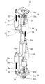
- FIG. 1A is a front view showing the overall configuration of the legged robot of this embodiment
- FIG. 1B is a left side view.
- the advancing direction of the legged robot is the x-axis direction
- the left-right direction as viewed from the legged robot is the y-axis direction
- the up-and-down direction of the legged robot is the z-axis direction
- the x-axis is the roll axis
- the y-axis is the pitch
- the axis and the z axis are the yaw axes.
- the left and right are the left and right when viewed from the legged robot side shown in FIGS. 1 to 3
- the front and rear are the front and rear when viewed from the legged robot side.
- the legged robot 10 is installed above the trunk 11, with two legs 12 installed below the trunk 11, two arms 13 installed on the upper left and right sides of the trunk 11, and the leg 11. It is composed of a single head 14 that is made to operate like a human.
- the two arm portions 13 are connected to the trunk portion 11 via a shoulder joint 16 and can rotate about the yaw axis and the roll axis with respect to the trunk portion 11.
- Each arm portion 13 includes an upper arm portion 13b closer to the shoulder, and a lower arm portion 13c closer to the hand portion 13a, with the elbow joint 17 as a boundary.
- the lower arm portion 13c can rotate around the yaw axis and the pitch axis with respect to the upper arm portion 13b.
- the leg portion 12 is connected to the pelvis 11a of the trunk portion 11 through the hip joint 8 so as to be swingable around the roll axis and the pitch axis.
- the legged robot 10 swings two legs 12 alternately around the pitch axis and the roll axis, and walks with a balance between two legs like a human.
- the leg 12 includes a hip joint 8, a thigh 12 a, a knee joint body 19, a crus 12 b, an ankle joint 9, and a foot 21, which are coupled to the trunk 11 in order from the top.
- the hip joint 8 includes a hip joint body 18 coupled to the trunk 11 and a hip joint 22 that connects the hip joint body 18 and the thigh 12a so as to be rotatable about the pitch axis and the roll axis.
- the ankle joint 9 includes an ankle joint main body 20 coupled to the foot portion 21, and an ankle joint joint 24 that connects the ankle joint main body 20 and the lower leg portion 12b so as to be rotatable around a roll axis and a pitch axis. Prepare. The foot 21 is landed on the walking road surface.
- the legged robot 10 is a robot configured to be remotely operable. When the operator operates an operation manipulator (not shown) located at a remote position, the legged robot 10 performs an operation according to the movement of the operation manipulator. It can be executed.
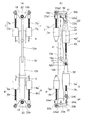
- FIGS. 2 shows a perspective view of the extended leg
- FIG. 3 (a) shows a front view of the extended leg
- FIG. 3 (b) shows a side view of the extended leg.
- the leg portion 12 includes a hip joint body 18, a thigh 12a, a knee joint body 19, a crus 12b, and an ankle joint body 20.
- a thigh 12 a is connected to the hip joint body 18 via a hip joint 22 so as to be rotatable about a roll axis and a pitch axis.
- the knee joint body 19 is connected to the thigh 12a so as to be rotatable around the pitch axis.
- the crus 12b is coupled to the knee joint body 19.
- An ankle joint body 20 is connected to the lower leg 12b through an ankle joint joint 24 so as to be rotatable about a roll axis and a pitch axis.
- a thigh auxiliary link 31 is provided behind the thigh 12a.
- a crus auxiliary link 32 is provided behind the crus 12b.
- the actuator includes two hip joint actuators 7 provided in front of the thigh 12a, one knee joint actuator 4 provided in the rear of the thigh 12a, and two ankle joint actuators 6 provided in front of the crus 12b, One ankle joint actuator 3 is provided behind the lower leg 12b.
- the hip joint body 18 is formed by bending a plate, and includes a quadrangular coupling portion 18a coupled to the body portion 11, and a pair of joint coupling portions 18b folded from a pair of opposite sides of the coupling portion 18a.
- the thigh part 12a is connected to the hip joint body 18 through a passive hip joint 22 so as to be rotatable around a roll axis and a pitch axis.
- the hip joint 22 has a cross-shaped main body 22a that forms a roll shaft 22a1 and a pitch shaft 22a2 that are orthogonal to each other.
- the roll shaft 22a1 of the main body portion 22a is rotatably connected to the pair of joint connecting portions 18b of the hip joint body 18 via a bearing.
- the pitch shaft 22a2 of the main body 22a is rotatably connected to the thigh 12a via a bearing.
- the arm 22 b is coupled to the main body portion 22 a of the hip joint 22.
- the upper end portion of the thigh auxiliary link 31 is coupled to the arm 22b so as to be rotatable around the pitch axis.
- the lower end of the thigh auxiliary link 31 is coupled to the bracket 12b1 of the crus 12b so as to be rotatable about the pitch axis.
- the thigh auxiliary link 31 is provided with a knee joint actuator 4 that expands and contracts the length between the upper end portion and the lower end portion of the thigh auxiliary link 31.
- the knee joint actuator 4 includes a cylindrical main body 4a and a shaft 4b that linearly moves in the axial direction with respect to the main body 4a.
- a spiral thread groove is formed on the outer peripheral surface of the shaft portion 4b.
- the main body portion 4a accommodates a ball screw nut (not shown) that is screwed into the thread groove of the shaft portion 4b, and a motor (not shown) that rotationally drives the ball screw nut. When the motor rotationally drives the ball screw nut, the shaft portion 4b linearly moves in the axial direction to extend and contract the thigh auxiliary link 31.
- a pair of left and right hip joint actuators 7 is bridged between the thigh 12a and the hip joint body 18.
- the hip joint actuator 7 is disposed in front of the thigh 12a, and the hip joint actuator 7 and the knee joint actuator 4 are disposed so as to straddle the thigh 12a.
- the hip joint actuator 7 includes a cylindrical main body portion 7a and a shaft portion 7b that linearly moves in the axial direction with respect to the main body portion 7a.
- a spiral thread groove is formed on the outer peripheral surface of the shaft portion 7b.
- the main body portion 7a accommodates a ball screw nut (not shown) that is screwed into the thread groove of the shaft portion 7b and a motor (not shown) that rotationally drives the ball screw nut. When the motor rotates the ball screw nut, the shaft portion 7b linearly moves in the axial direction.
- the shaft portion 7b of the hip joint actuator 7 is rotatably connected to the hip joint body 18 via a spherical bearing.
- the main body 7a of the hip joint actuator 7 is rotatably connected to the thigh 12a via a spherical bearing.
- the thigh 12a rotates around the pitch axis 22a2 with respect to the hip joint body 18.
- the thigh 12a rotates around the roll shaft 22a1 with respect to the hip joint body 18.
- the thigh 12a can be rotated around the pitch axis 22a2 and the roll axis 22a1 with respect to the hip joint body 18.
- a two-degree-of-freedom passive hip joint 22 is interposed between the hip joint body 18 and the thigh 12a, and two hip joint actuators 7 are placed between the hip joint body 18 and the thigh 12a.
- two motors functioning as active joints are provided on the pitch axis and the roll axis of the hip joint body 18, a force several times larger can be generated. Since the hip joint actuator 7 for obtaining a necessary force can be reduced in size, the leg portion 12 can be reduced in size.
- the knee joint body 19 is attached to the lower end of the thigh 12a so as to be rotatable around the pitch axis 19a.
- the crus 12b is coupled to the knee joint body 19.
- the ankle joint body 20 is connected to the crus part 12b via an ankle joint joint 24 so as to be rotatable around a roll axis and a pitch axis.
- the ankle joint body 20 is formed by bending a plate, and has a quadrangular coupling portion 20a (see FIG. 2) coupled to a foot portion 21 (see FIG. 1A) and a pair of sides facing the coupling portion 20a. And a pair of joint connecting portions 20b bent from above.
- the ankle joint joint 24 has a cross-shaped main body portion 24a constituting a roll shaft 24a1 and a pitch shaft 24a2 that are orthogonal to each other.
- the roll shaft 24a1 of the main body portion 24a is rotatably connected to the pair of joint connecting portions 20b of the ankle joint main body 20 via a bearing.
- the pitch shaft 24a2 of the main body 24a is rotatably connected to the crus 12b via a bearing.
- the arm 24 b is coupled to the main body 24 a of the ankle joint joint 24.
- a lower end portion of the crus auxiliary link 32 is coupled to the arm 24b so as to be rotatable around the pitch axis.
- the upper end portion of the crus auxiliary link 32 is connected to the bracket 12b1 of the crus portion 12b so as to be rotatable around the pitch axis.
- the crus auxiliary link 32 is provided with an ankle joint actuator 3 that expands and contracts the length between the upper end and the lower end of the crus auxiliary link 32.
- the ankle joint actuator 3 includes a cylindrical main body 3a and a shaft 3b that linearly moves in the axial direction with respect to the main body 3a.
- a spiral thread groove is formed on the outer peripheral surface of the shaft portion 3b.
- the main body portion 3a accommodates a ball screw nut (not shown) that is screwed into the thread groove of the shaft portion 3b and a motor (not shown) that rotationally drives the ball screw nut.
- the motor rotates the ball screw nut, the shaft portion 3b linearly moves in the axial direction.
- the ankle joint actuator 3 is expanded and contracted, the ankle joint body 20 rotates around the pitch axis.
- a pair of left and right ankle joint actuators 6 are bridged between the crus 12b and the ankle joint body 20.
- the ankle joint actuator 6 is disposed in front of the crus 12b, and the ankle joint actuator 6 and the ankle joint actuator 3 are disposed so as to straddle the crus 12b.
- the ankle joint actuator 6 includes a cylindrical main body 6a and a shaft 6b that linearly moves in the axial direction with respect to the main body 6a.
- a spiral thread groove is formed on the outer peripheral surface of the shaft portion 6b.
- a ball screw nut (not shown) that is screwed into the thread groove of the shaft portion 6b and a motor (not shown) that rotationally drives the ball screw nut are housed in the main body portion. When the motor rotates the ball screw nut, the shaft portion 6b linearly moves in the axial direction.
- the shaft portion 6b of the ankle joint actuator 6 is rotatably connected to the ankle joint body 20 via a spherical bearing.
- the main body 6a of the ankle joint actuator 6 is rotatably connected to the crus 12b via a spherical bearing.
- the ankle joint body 20 rotates around the pitch axis 24a2 with respect to the crus 12b.
- the ankle joint body 20 rotates around the roll shaft 24a1 relative to the crus 12b.
- the motors of the hip joint actuator 7, the knee joint actuator 4, and the ankle joint actuators 3 and 6 are controlled by a driver.
- the driver uses a power converter such as a PWM (pulse width modulation) inverter that supplies power to the motor, a sensor that detects the speed and position of the output shaft of the motor, a command from the operation manipulator, and information from the sensor.
- a controller for controlling is provided.
- the drivers communicate with each other and can be synchronized without a separate control box.
- the parallel link 41 includes four links a1, b1, c1, and d1 that form a parallelogram.
- the link a1 includes the arm 22b of the hip joint 22, the link c1 includes the knee joint body 19 (the knee joint body 19 and the lower leg 12b), the link b1 includes the thigh 12a, and the link d1 includes the thigh auxiliary link 31. .
- FIG. 4 (a) shows a state in which the thigh 12a is rotated forward by the hip joint actuator 7 to rotate the thigh 12a around the pitch axis 22a2.
- the posture of the knee joint body 19 (the knee joint body 19 and the lower leg 12b) with respect to the hip joint body 18 is kept constant by the action of the parallel link 41. That is, even if the thigh 12a is rotated as shown in FIG. 4 (a), the posture of the knee joint body 19 (the knee joint body 19 and the lower leg 12b) remains in the vertical direction as in FIG. 4 (b). It is suitable. Then, as shown in FIG.
- the knee joint actuator 4 contracts the thigh auxiliary link 31, whereby the knee joint body 19 (the knee joint body 19 and the knee joint body 19 facing the vertical direction) is bent so that the knee joint is bent.
- the posture of the crus 12b) can be changed.
- the human thigh also has a muscle corresponding to the thigh auxiliary link 31 behind, and the posture of the knee joint body can be changed by contracting the muscle.
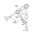
- FIG. 5 is a diagram for explaining the reason why the energy of the knee joint actuator 4 can be reduced by expanding and contracting the thigh auxiliary link 31.
- an actuator is provided in a hip joint and a knee joint
- the thigh 12a is swung by an angle ⁇ 1 from the state where the entire leg is upright, and at the same time the lower thigh 12b is bent by ⁇ 2 with respect to the axis of the thigh 12a.
- ⁇ 2 2 ⁇ 1
- energy for swinging the thigh 12a by ⁇ 1 is E1
- the energy required to move the thigh 12a by the hip joint actuator 7 by ⁇ 1 is E1.
- the thigh 12a swings the lower leg bends with respect to the axis of the thigh 12a by an angle ⁇ 1, as shown in FIG. Since the crus 12b is bent at an angle ⁇ 1 by the action of the parallel link, as shown in FIG. 4 (b), in order to make the crus 12b 2 ⁇ 1 with respect to the axis of the thigh 12a, the knee joint The angle at which the lower leg 12b is bent by the actuator 4 is ⁇ 1, and the energy required for this is E1.
- the total energy required to complete the bending of the leg is 2E1. That is, the actuator provided in the knee joint in the comparative example is large because it requires 2E1 output, but in this embodiment, the knee joint actuator 4 that stops at E1 output may be provided. Miniaturization of the structure is achieved and energy consumption is reduced.
- an ankle joint with respect to the crus 12b is provided by arranging a crus auxiliary link 32 behind the crus 12b and extending and retracting the crus auxiliary link 32 by the ankle joint actuator 3.
- the posture of the main body 20 can be changed.
- the crus auxiliary link 32 By disposing the crus auxiliary link 32 behind the crus 12b and extending / contracting the crus auxiliary link 32, the posture of the ankle joint body 20 can be changed with less energy like a human.
- the hip joint body and the thigh are connected to be rotatable about the roll axis and the pitch axis, but the hip joint body and the thigh are connected to be rotatable only about the pitch axis.
- one end of the thigh auxiliary link constituting the parallel link is connected to the hip joint body so as to be rotatable around the pitch axis, and the other end is connected to the knee joint body so as to be rotatable around the pitch axis.
- a direct acting actuator motor is used as an actuator spanned between the hip joint body and the thigh, but a rotary actuator can also be used.
- the rotary actuator includes a motor coupled to the thigh, a servo horn coupled to the motor output, one end rotatably connected to the servo horn via a spherical bearing, and the other end hip joint It can be comprised from the link connected with a main body through a spherical bearing so that rotation is possible.
- the knee joint body and the crus are coupled, but the knee joint body and the crus can also be coupled to be rotatable about the pitch axis.
- the hip joint body is coupled to the trunk, but the hip joint body and the trunk can also be configured from an integral frame.
- the ankle joint main body is coupled to the foot portion, but the ankle joint main body and the foot portion can also be configured from an integral frame.
- a motor is used as a drive source for swinging the leg portion, but various other devices such as a pneumatic or hydraulic cylinder, a linear motor, and an artificial muscle actuator can be used as the drive source. Can do.
Landscapes
- Engineering & Computer Science (AREA)
- Robotics (AREA)
- Mechanical Engineering (AREA)
- Manipulator (AREA)
- Rehabilitation Tools (AREA)
Priority Applications (4)
| Application Number | Priority Date | Filing Date | Title |
|---|---|---|---|
| KR1020147036367A KR101979480B1 (ko) | 2012-05-31 | 2013-04-11 | 다리식 로봇의 하지 구조 및 다리식 로봇 |
| DE112013002741.0T DE112013002741T5 (de) | 2012-05-31 | 2013-04-11 | Untere Gliedmaßenstruktur für Laufroboter und Laufroboter |
| CN201380028692.4A CN104349871B (zh) | 2012-05-31 | 2013-04-11 | 腿式机器人的下肢结构以及腿式机器人 |
| US14/401,892 US9446514B2 (en) | 2012-05-31 | 2013-04-11 | Lower limb structure for legged robot, and legged robot |
Applications Claiming Priority (2)
| Application Number | Priority Date | Filing Date | Title |
|---|---|---|---|
| JP2012-124511 | 2012-05-31 | ||
| JP2012124511A JP5976401B2 (ja) | 2012-05-31 | 2012-05-31 | 脚式ロボットの下肢構造及び脚式ロボット |
Publications (1)
| Publication Number | Publication Date |
|---|---|
| WO2013179782A1 true WO2013179782A1 (ja) | 2013-12-05 |
Family
ID=49672990
Family Applications (1)
| Application Number | Title | Priority Date | Filing Date |
|---|---|---|---|
| PCT/JP2013/060940 Ceased WO2013179782A1 (ja) | 2012-05-31 | 2013-04-11 | 脚式ロボットの下肢構造及び脚式ロボット |
Country Status (6)
| Country | Link |
|---|---|
| US (1) | US9446514B2 (enExample) |
| JP (1) | JP5976401B2 (enExample) |
| KR (1) | KR101979480B1 (enExample) |
| CN (1) | CN104349871B (enExample) |
| DE (1) | DE112013002741T5 (enExample) |
| WO (1) | WO2013179782A1 (enExample) |
Cited By (11)
| Publication number | Priority date | Publication date | Assignee | Title |
|---|---|---|---|---|
| CN104401419A (zh) * | 2014-11-25 | 2015-03-11 | 北京工业大学 | 一种基于气动人工肌肉的新型双足仿人机器人系统 |
| CN106726362A (zh) * | 2017-03-03 | 2017-05-31 | 中国科学院合肥物质科学研究院 | 用于外骨骼机器人的髋膝一体化关节装置及外骨骼机器人 |
| CN110236884A (zh) * | 2019-07-04 | 2019-09-17 | 青岛市中心医院 | 一种全方位智能髋膝踝关节被动康复训练器 |
| CN110696941A (zh) * | 2019-09-19 | 2020-01-17 | 浙江工业大学 | 一种冗余混联电液混合驱动拟人机械腿 |
| JP2020102997A (ja) * | 2018-12-25 | 2020-07-02 | 株式会社神戸製鋼所 | アクチュエータ装置およびこれを用いた移動機構、装備品 |
| CN111388279A (zh) * | 2020-02-21 | 2020-07-10 | 南方科技大学 | 柔性助行外骨骼 |
| CN111516773A (zh) * | 2020-04-02 | 2020-08-11 | 之江实验室 | 一种具有多种运动模式的可重构双足机器人 |
| CN114161472A (zh) * | 2021-11-17 | 2022-03-11 | 深圳市优必选科技股份有限公司 | 髋腰关节结构及人形机器人 |
| CN116767380A (zh) * | 2023-08-07 | 2023-09-19 | 太原理工大学 | 一种基于气动软体驱动器的仿生腿弹跳机器人 |
| CN118990599A (zh) * | 2024-08-23 | 2024-11-22 | 哈尔滨工业大学 | 一种液压驱动的人形机器人盆骨 |
| CN119973959A (zh) * | 2025-03-13 | 2025-05-13 | 南京理工大学 | 一种髋膝关节助行外骨骼机器人 |
Families Citing this family (78)
| Publication number | Priority date | Publication date | Assignee | Title |
|---|---|---|---|---|
| US9789603B2 (en) | 2011-04-29 | 2017-10-17 | Sarcos Lc | Teleoperated robotic system |
| US9764464B2 (en) * | 2011-08-03 | 2017-09-19 | The Boeing Company | Robot including telescopic assemblies for positioning an end effector |
| US9616580B2 (en) | 2012-05-14 | 2017-04-11 | Sarcos Lc | End effector for a robotic arm |
| JP2014209172A (ja) * | 2013-03-25 | 2014-11-06 | 太陽インキ製造株式会社 | 感光性樹脂組成物、その硬化被膜およびプリント配線板 |
| US10406676B2 (en) | 2014-05-06 | 2019-09-10 | Sarcos Lc | Energy recovering legged robotic device |
| US10512583B2 (en) | 2014-05-06 | 2019-12-24 | Sarcos Lc | Forward or rearward oriented exoskeleton |
| US10533542B2 (en) | 2014-05-06 | 2020-01-14 | Sarcos Lc | Rapidly modulated hydraulic supply for a robotic device |
| US10766133B2 (en) * | 2014-05-06 | 2020-09-08 | Sarcos Lc | Legged robotic device utilizing modifiable linkage mechanism |
| KR101627138B1 (ko) * | 2014-09-04 | 2016-06-07 | 한국생산기술연구원 | 보행로봇의 다리 구조체 |
| JP6228097B2 (ja) * | 2014-10-06 | 2017-11-08 | 本田技研工業株式会社 | 移動ロボット |
| JP6677970B2 (ja) * | 2015-02-20 | 2020-04-08 | 川崎重工業株式会社 | 産業用ロボット |
| CN106143665A (zh) * | 2015-04-21 | 2016-11-23 | 电子科技大学 | 一种可弯曲机器人躯干机构 |
| GB2538714A (en) * | 2015-05-25 | 2016-11-30 | Robotical Ltd | Robot Leg |
| US10189519B2 (en) * | 2015-05-29 | 2019-01-29 | Oregon State University | Leg configuration for spring-mass legged locomotion |
| US9878751B1 (en) | 2015-10-08 | 2018-01-30 | Boston Dynamics, Inc. | Three-piston ankle mechanism of a legged robot and associated control system |
| CN106741277B (zh) * | 2015-11-20 | 2020-10-30 | 沈阳新松机器人自动化股份有限公司 | 一种混合式机械腿机构 |
| CN105480322B (zh) * | 2015-12-17 | 2018-01-30 | 哈尔滨龙海特机器人科技有限公司 | 一种用于高速奔跑足式机器人并联腿结构 |
| US10632626B2 (en) * | 2016-06-07 | 2020-04-28 | Worcester Polytechnic Institute | Biologically-inspired joints and systems and methods of use thereof |
| CN106314588A (zh) * | 2016-09-19 | 2017-01-11 | 南宁邃丛赋语科技开发有限责任公司 | 一种自动化控制的两足行走机器人 |
| KR20180035626A (ko) * | 2016-09-29 | 2018-04-06 | 최호림 | 로봇의 보행장치 |
| CN106493738A (zh) * | 2016-10-26 | 2017-03-15 | 河南工业大学 | 一种幼儿助教用双腿行走仿人教育机器人 |
| US10821614B2 (en) | 2016-11-11 | 2020-11-03 | Sarcos Corp. | Clutched joint modules having a quasi-passive elastic actuator for a robotic assembly |
| US10765537B2 (en) | 2016-11-11 | 2020-09-08 | Sarcos Corp. | Tunable actuator joint modules having energy recovering quasi-passive elastic actuators for use within a robotic system |
| US10828767B2 (en) | 2016-11-11 | 2020-11-10 | Sarcos Corp. | Tunable actuator joint modules having energy recovering quasi-passive elastic actuators with internal valve arrangements |
| US10919161B2 (en) | 2016-11-11 | 2021-02-16 | Sarcos Corp. | Clutched joint modules for a robotic system |
| KR101876252B1 (ko) * | 2016-11-22 | 2018-07-10 | 한국과학기술연구원 | 병렬식 링크 구조를 포함하는 로봇 하체, 이를 포함하는 보행 로봇 장치 |
| US11511446B2 (en) * | 2016-11-24 | 2022-11-29 | Kawasaki Jukogyo Kabushiki Kaisha | Joint structure for robot |
| US10253855B2 (en) * | 2016-12-15 | 2019-04-09 | Boston Dynamics, Inc. | Screw actuator for a legged robot |
| US10337561B2 (en) * | 2016-12-15 | 2019-07-02 | Boston Dynamics, Inc. | Transmission with integrated overload protection for a legged robot |
| CN106672105B (zh) * | 2017-03-01 | 2023-03-21 | 吉林大学 | 一种具有张拉整体结构的仿生四足机器人后肢 |
| CN106726363B (zh) * | 2017-03-13 | 2023-11-17 | 东北大学 | 一种可穿戴仿生液压下肢康复助行机械装置 |
| WO2018170638A1 (zh) * | 2017-03-18 | 2018-09-27 | 深圳市方鹏科技有限公司 | 一种机械人的下肢行走机构系统 |
| US10843330B2 (en) | 2017-12-07 | 2020-11-24 | Sarcos Corp. | Resistance-based joint constraint for a master robotic system |
| US11331809B2 (en) | 2017-12-18 | 2022-05-17 | Sarcos Corp. | Dynamically controlled robotic stiffening element |
| CN108082325A (zh) * | 2017-12-21 | 2018-05-29 | 江苏集萃智能制造技术研究所有限公司 | 一种液压驱动的双足机器人下肢机构 |
| CN109969284A (zh) * | 2017-12-28 | 2019-07-05 | 沈阳新松机器人自动化股份有限公司 | 混合式机械腿机构和双足机器人 |
| CN107985439B (zh) * | 2017-12-29 | 2023-12-05 | 北京钢铁侠科技有限公司 | 一种仿人机器人腿部机构 |
| CN108095983A (zh) * | 2018-02-05 | 2018-06-01 | 河北工程大学 | 一种用于高位截肢患者的两足行走机构 |
| US10719085B2 (en) * | 2018-02-22 | 2020-07-21 | Boston Dynamics, Inc. | Mobile robot sitting and standing |
| KR102586197B1 (ko) | 2018-12-10 | 2023-10-11 | 삼성전자주식회사 | 운동 보조 장치 |
| WO2020123833A1 (en) * | 2018-12-14 | 2020-06-18 | Moog Inc. | Humanoid lower body robot electro hydrostatic actuating ankle |
| US10906191B2 (en) | 2018-12-31 | 2021-02-02 | Sarcos Corp. | Hybrid robotic end effector |
| US11241801B2 (en) | 2018-12-31 | 2022-02-08 | Sarcos Corp. | Robotic end effector with dorsally supported actuation mechanism |
| US11351675B2 (en) | 2018-12-31 | 2022-06-07 | Sarcos Corp. | Robotic end-effector having dynamic stiffening elements for conforming object interaction |
| CN110696944A (zh) * | 2019-11-11 | 2020-01-17 | 路邦科技授权有限公司 | 一种仿生机器人的腿部远程控制系统及其控制方法 |
| KR102256225B1 (ko) * | 2019-11-20 | 2021-05-26 | 주식회사 엔젤로보틱스 | 하체 보조로봇 |
| KR20210065644A (ko) | 2019-11-27 | 2021-06-04 | 주식회사 에프알티 | 공압 모듈을 구비하는 하지용 웨어러블 외골격 로봇 |
| CN111017063B (zh) * | 2019-12-17 | 2022-03-22 | 上海哲谦应用科技有限公司 | 一种直驱式类人双足机器人 |
| CN110962959B (zh) * | 2019-12-24 | 2022-03-08 | 深圳市行者机器人技术有限公司 | 一种机器人及其机械腿 |
| CN111098951A (zh) * | 2019-12-30 | 2020-05-05 | 深圳市优必选科技股份有限公司 | 类人形机器人及其腿部结构 |
| CN112319209A (zh) * | 2020-11-18 | 2021-02-05 | 内蒙古第一机械集团股份有限公司 | 一种适用于机器人腿部关节运动的驱动装置 |
| US11833676B2 (en) | 2020-12-07 | 2023-12-05 | Sarcos Corp. | Combining sensor output data to prevent unsafe operation of an exoskeleton |
| US11794345B2 (en) | 2020-12-31 | 2023-10-24 | Sarcos Corp. | Unified robotic vehicle systems and methods of control |
| CN112937717B (zh) * | 2021-02-03 | 2023-06-13 | 南方科技大学 | 一种仿生机械腿及仿生机器人 |
| CN112937720B (zh) * | 2021-02-05 | 2021-09-28 | 重庆工程职业技术学院 | 一种行走机器人 |
| CN112874656B (zh) * | 2021-03-23 | 2023-03-31 | 上海智能制造功能平台有限公司 | 机器人的腿部机构及机器人 |
| CN115195899B (zh) * | 2021-04-09 | 2023-06-30 | 暗物智能科技(广州)有限公司 | 一种轮足切换式机器人 |
| CN113635992B (zh) * | 2021-06-15 | 2023-02-10 | 上海大学 | 一种双关节气动人工肌肉驱动的仿生跳跃腿 |
| CN113335416B (zh) * | 2021-07-16 | 2024-11-12 | 深圳市行者机器人技术有限公司 | 一种髋关节机构及足式机器人 |
| CN113401246B (zh) * | 2021-07-21 | 2022-08-12 | 北京理工大学 | 一种仿生机器人腿足机构 |
| CN114056450B (zh) * | 2021-11-26 | 2022-11-29 | 合肥工业大学 | 一种用于无人变胞车的轮足式折叠腿 |
| CN113998028A (zh) * | 2021-12-22 | 2022-02-01 | 成都理工大学 | 一种足式机器人双自由度基节结构 |
| CN115056883A (zh) * | 2022-05-06 | 2022-09-16 | 纯米科技(上海)股份有限公司 | 腿部结构及四足机器人 |
| CN115056884B (zh) * | 2022-06-27 | 2023-10-17 | 北京工业大学 | 具有差分关节解耦与惯量上移特性的仿人机器人腿结构 |
| CN115415997B (zh) * | 2022-08-16 | 2025-07-29 | 山东科技大学 | 一种拮抗式气动肌肉下肢动力外骨骼 |
| US11826907B1 (en) | 2022-08-17 | 2023-11-28 | Sarcos Corp. | Robotic joint system with length adapter |
| US11717956B1 (en) | 2022-08-29 | 2023-08-08 | Sarcos Corp. | Robotic joint system with integrated safety |
| WO2024098070A1 (en) | 2022-11-04 | 2024-05-10 | Sarcos Corp. | Robotic end-effector having dynamic stiffening elements with resilient spacers for conforming object interaction |
| US11924023B1 (en) | 2022-11-17 | 2024-03-05 | Sarcos Corp. | Systems and methods for redundant network communication in a robot |
| US11897132B1 (en) | 2022-11-17 | 2024-02-13 | Sarcos Corp. | Systems and methods for redundant network communication in a robot |
| JP2024102435A (ja) * | 2023-01-19 | 2024-07-31 | トヨタ自動車株式会社 | ロボットの関節構造 |
| CN115892280A (zh) * | 2023-02-10 | 2023-04-04 | 哈尔滨工业大学 | 一种液压双足单腿 |
| CN116605329A (zh) * | 2023-05-17 | 2023-08-18 | 傅利叶动力(北京)科技有限公司 | 双足机器人的下肢组件 |
| CN116729520B (zh) * | 2023-08-11 | 2023-10-20 | 太原理工大学 | 一种基于双层波纹管气动软体驱动器的仿生四足机器人 |
| WO2025049602A1 (en) * | 2023-08-28 | 2025-03-06 | University Of Southern California | A bipedal robot for dynamic and robust location in diverse environments |
| CN117961965B (zh) * | 2024-03-08 | 2025-04-29 | 哈尔滨工业大学 | 一种基于3d打印的仿生六自由度异形机械臂 |
| CN118514784B (zh) * | 2024-07-19 | 2024-11-29 | 南京理工大学 | 一种可竖直站立的两足步行机器人下肢结构 |
| CN119078989B (zh) * | 2024-10-23 | 2025-12-09 | 广州小鹏汽车科技有限公司 | 腿部结构及人形机器人 |
Citations (4)
| Publication number | Priority date | Publication date | Assignee | Title |
|---|---|---|---|---|
| JPH10512503A (ja) * | 1995-11-06 | 1998-12-02 | プルステック オイ | 脚部機構 |
| JP2004202676A (ja) * | 2002-12-23 | 2004-07-22 | Samsung Electronics Co Ltd | 2足歩行ロボット |
| JP2006043871A (ja) * | 2004-06-28 | 2006-02-16 | Rikogaku Shinkokai | 歩行装置 |
| JP2009101456A (ja) * | 2007-10-23 | 2009-05-14 | Honda Motor Co Ltd | 2足歩行ロボット |
Family Cites Families (11)
| Publication number | Priority date | Publication date | Assignee | Title |
|---|---|---|---|---|
| US6109378A (en) | 1995-11-06 | 2000-08-29 | Plustech Oy | Leg mechanism |
| CN1293607A (zh) * | 1999-01-28 | 2001-05-02 | 索尼公司 | 机器人装置用关节装置及脚式步行机器人装置 |
| CN1081515C (zh) * | 1999-04-05 | 2002-03-27 | 张平顺 | 两腿步行机 |
| EP2017042B1 (en) * | 2000-11-20 | 2010-09-15 | Sony Corporation | Motion controller and motion control method for legged walking robot, and robot apparatus |
| JP2002264046A (ja) | 2001-03-12 | 2002-09-18 | Rikogaku Shinkokai | マスター・スレーブ式遠隔操作型二足歩行ロボット |
| KR20040068438A (ko) * | 2003-01-25 | 2004-07-31 | 삼성전자주식회사 | 보행식 로봇 및 그 위치이동방법 |
| JP4526332B2 (ja) * | 2004-09-06 | 2010-08-18 | 本田技研工業株式会社 | 脚式移動ロボットの脚体関節アシスト装置 |
| US8138707B2 (en) * | 2007-10-23 | 2012-03-20 | Honda Motor Co., Ltd. | Bipedal walking robot |
| KR101484943B1 (ko) * | 2008-05-30 | 2015-01-21 | 삼성전자 주식회사 | 보행로봇 |
| KR101464125B1 (ko) * | 2008-06-05 | 2014-12-04 | 삼성전자주식회사 | 보행로봇 |
| JP5539040B2 (ja) * | 2010-06-04 | 2014-07-02 | 本田技研工業株式会社 | 脚式移動ロボット |
-
2012
- 2012-05-31 JP JP2012124511A patent/JP5976401B2/ja active Active
-
2013
- 2013-04-11 US US14/401,892 patent/US9446514B2/en active Active
- 2013-04-11 DE DE112013002741.0T patent/DE112013002741T5/de active Pending
- 2013-04-11 CN CN201380028692.4A patent/CN104349871B/zh active Active
- 2013-04-11 WO PCT/JP2013/060940 patent/WO2013179782A1/ja not_active Ceased
- 2013-04-11 KR KR1020147036367A patent/KR101979480B1/ko active Active
Patent Citations (4)
| Publication number | Priority date | Publication date | Assignee | Title |
|---|---|---|---|---|
| JPH10512503A (ja) * | 1995-11-06 | 1998-12-02 | プルステック オイ | 脚部機構 |
| JP2004202676A (ja) * | 2002-12-23 | 2004-07-22 | Samsung Electronics Co Ltd | 2足歩行ロボット |
| JP2006043871A (ja) * | 2004-06-28 | 2006-02-16 | Rikogaku Shinkokai | 歩行装置 |
| JP2009101456A (ja) * | 2007-10-23 | 2009-05-14 | Honda Motor Co Ltd | 2足歩行ロボット |
Cited By (16)
| Publication number | Priority date | Publication date | Assignee | Title |
|---|---|---|---|---|
| CN104401419A (zh) * | 2014-11-25 | 2015-03-11 | 北京工业大学 | 一种基于气动人工肌肉的新型双足仿人机器人系统 |
| CN106726362A (zh) * | 2017-03-03 | 2017-05-31 | 中国科学院合肥物质科学研究院 | 用于外骨骼机器人的髋膝一体化关节装置及外骨骼机器人 |
| CN106726362B (zh) * | 2017-03-03 | 2023-04-07 | 中国科学院合肥物质科学研究院 | 用于外骨骼机器人的髋膝一体化关节装置及外骨骼机器人 |
| JP7150589B2 (ja) | 2018-12-25 | 2022-10-11 | 株式会社神戸製鋼所 | アクチュエータ装置およびこれを用いた移動機構、装備品 |
| JP2020102997A (ja) * | 2018-12-25 | 2020-07-02 | 株式会社神戸製鋼所 | アクチュエータ装置およびこれを用いた移動機構、装備品 |
| CN110236884A (zh) * | 2019-07-04 | 2019-09-17 | 青岛市中心医院 | 一种全方位智能髋膝踝关节被动康复训练器 |
| CN110236884B (zh) * | 2019-07-04 | 2024-05-03 | 青岛市中心医院 | 一种全方位智能髋膝踝关节被动康复训练器 |
| CN110696941A (zh) * | 2019-09-19 | 2020-01-17 | 浙江工业大学 | 一种冗余混联电液混合驱动拟人机械腿 |
| CN110696941B (zh) * | 2019-09-19 | 2024-04-09 | 浙江工业大学 | 一种冗余混联电液混合驱动拟人机械腿 |
| CN111388279A (zh) * | 2020-02-21 | 2020-07-10 | 南方科技大学 | 柔性助行外骨骼 |
| CN111516773A (zh) * | 2020-04-02 | 2020-08-11 | 之江实验室 | 一种具有多种运动模式的可重构双足机器人 |
| CN114161472A (zh) * | 2021-11-17 | 2022-03-11 | 深圳市优必选科技股份有限公司 | 髋腰关节结构及人形机器人 |
| CN114161472B (zh) * | 2021-11-17 | 2024-02-13 | 深圳市优必选科技股份有限公司 | 髋腰关节结构及人形机器人 |
| CN116767380A (zh) * | 2023-08-07 | 2023-09-19 | 太原理工大学 | 一种基于气动软体驱动器的仿生腿弹跳机器人 |
| CN118990599A (zh) * | 2024-08-23 | 2024-11-22 | 哈尔滨工业大学 | 一种液压驱动的人形机器人盆骨 |
| CN119973959A (zh) * | 2025-03-13 | 2025-05-13 | 南京理工大学 | 一种髋膝关节助行外骨骼机器人 |
Also Published As
| Publication number | Publication date |
|---|---|
| CN104349871A (zh) | 2015-02-11 |
| DE112013002741T5 (de) | 2015-03-19 |
| JP5976401B2 (ja) | 2016-08-23 |
| US9446514B2 (en) | 2016-09-20 |
| KR101979480B1 (ko) | 2019-08-28 |
| KR20150016362A (ko) | 2015-02-11 |
| US20150122559A1 (en) | 2015-05-07 |
| JP2013248699A (ja) | 2013-12-12 |
| CN104349871B (zh) | 2017-08-25 |
Similar Documents
| Publication | Publication Date | Title |
|---|---|---|
| JP5976401B2 (ja) | 脚式ロボットの下肢構造及び脚式ロボット | |
| JP5872846B2 (ja) | ロボットの関節構造及びこの関節構造が組み込まれた人間型ロボット | |
| TWI522217B (zh) | 機器人之關節構造及組入有該關節構造之機器人 | |
| WO2013179783A1 (ja) | 脚式ロボットの下肢構造及び脚式ロボット | |
| US8042627B2 (en) | Walking robot | |
| JP6803338B2 (ja) | 2自由度の駆動機構 | |
| KR101457147B1 (ko) | 인간형 로봇과 그 어깨관절 어셈블리 | |
| JP5373880B2 (ja) | 脚式ロボット | |
| CN101391417B (zh) | 一种基于被动运动方式的双足类人机器人 | |
| JPH03184782A (ja) | 脚式歩行ロボットの関節構造 | |
| KR20100082225A (ko) | 로봇용 관절구동장치 및 이를 구비한 로봇 | |
| JP2013248699A5 (enExample) | ||
| CN101934525A (zh) | 仿人机器人可变刚度柔性关节设计 | |
| CN105121100B (zh) | 紧凑型并联运动机器人 | |
| CN105109572A (zh) | 一种用于腿臂融合操作的轮腿式机器人的单腿结构 | |
| CN105599822A (zh) | 一种基于柔性驱动器的欠驱动双足步行机器人 | |
| JP2001239478A (ja) | 脚式移動ロボット及び脚式移動ロボットのための可動脚ユニット連結構造 | |
| JP5681564B2 (ja) | ロボット | |
| JP5877686B2 (ja) | ロボットの関節構造及びこの関節構造が組み込まれた人間型ロボット | |
| JP3375202B2 (ja) | 2関節同時駆動源を装備した2関節アーム機構とその動作制御方法 | |
| JP2003266358A (ja) | ロボット装置及び関節軸駆動装置 | |
| WO2023281796A1 (ja) | 直動機構 | |
| JP6705658B2 (ja) | 脚式移動ロボット | |
| KR102705454B1 (ko) | 하지 보조 로봇 | |
| JP5879068B2 (ja) | ロボットの関節アクチュエータ及び脚式移動ロボット |
Legal Events
| Date | Code | Title | Description |
|---|---|---|---|
| 121 | Ep: the epo has been informed by wipo that ep was designated in this application |
Ref document number: 13797758 Country of ref document: EP Kind code of ref document: A1 |
|
| WWE | Wipo information: entry into national phase |
Ref document number: 14401892 Country of ref document: US |
|
| WWE | Wipo information: entry into national phase |
Ref document number: 1120130027410 Country of ref document: DE Ref document number: 112013002741 Country of ref document: DE |
|
| ENP | Entry into the national phase |
Ref document number: 20147036367 Country of ref document: KR Kind code of ref document: A |
|
| 122 | Ep: pct application non-entry in european phase |
Ref document number: 13797758 Country of ref document: EP Kind code of ref document: A1 |