WO2013176251A1 - 放射線画像検出装置およびその作動方法、並びに放射線撮影システム - Google Patents
放射線画像検出装置およびその作動方法、並びに放射線撮影システム Download PDFInfo
- Publication number
- WO2013176251A1 WO2013176251A1 PCT/JP2013/064474 JP2013064474W WO2013176251A1 WO 2013176251 A1 WO2013176251 A1 WO 2013176251A1 JP 2013064474 W JP2013064474 W JP 2013064474W WO 2013176251 A1 WO2013176251 A1 WO 2013176251A1
- Authority
- WO
- WIPO (PCT)
- Prior art keywords
- dose
- radiation
- irradiation
- signal
- time
- Prior art date
- Legal status (The legal status is an assumption and is not a legal conclusion. Google has not performed a legal analysis and makes no representation as to the accuracy of the status listed.)
- Ceased
Links
Images





Classifications
-
- A—HUMAN NECESSITIES
- A61—MEDICAL OR VETERINARY SCIENCE; HYGIENE
- A61B—DIAGNOSIS; SURGERY; IDENTIFICATION
- A61B6/00—Apparatus or devices for radiation diagnosis; Apparatus or devices for radiation diagnosis combined with radiation therapy equipment
- A61B6/54—Control of apparatus or devices for radiation diagnosis
- A61B6/542—Control of apparatus or devices for radiation diagnosis involving control of exposure
-
- G—PHYSICS
- G01—MEASURING; TESTING
- G01N—INVESTIGATING OR ANALYSING MATERIALS BY DETERMINING THEIR CHEMICAL OR PHYSICAL PROPERTIES
- G01N23/00—Investigating or analysing materials by the use of wave or particle radiation, e.g. X-rays or neutrons, not covered by groups G01N3/00 – G01N17/00, G01N21/00 or G01N22/00
- G01N23/02—Investigating or analysing materials by the use of wave or particle radiation, e.g. X-rays or neutrons, not covered by groups G01N3/00 – G01N17/00, G01N21/00 or G01N22/00 by transmitting the radiation through the material
- G01N23/04—Investigating or analysing materials by the use of wave or particle radiation, e.g. X-rays or neutrons, not covered by groups G01N3/00 – G01N17/00, G01N21/00 or G01N22/00 by transmitting the radiation through the material and forming images of the material
-
- G—PHYSICS
- G01—MEASURING; TESTING
- G01T—MEASUREMENT OF NUCLEAR OR X-RADIATION
- G01T1/00—Measuring X-radiation, gamma radiation, corpuscular radiation, or cosmic radiation
- G01T1/02—Dosimeters
- G01T1/026—Semiconductor dose-rate meters
-
- G—PHYSICS
- G01—MEASURING; TESTING
- G01T—MEASUREMENT OF NUCLEAR OR X-RADIATION
- G01T1/00—Measuring X-radiation, gamma radiation, corpuscular radiation, or cosmic radiation
- G01T1/15—Instruments in which pulses generated by a radiation detector are integrated, e.g. by a diode pump circuit
-
- H—ELECTRICITY
- H04—ELECTRIC COMMUNICATION TECHNIQUE
- H04N—PICTORIAL COMMUNICATION, e.g. TELEVISION
- H04N23/00—Cameras or camera modules comprising electronic image sensors; Control thereof
- H04N23/30—Cameras or camera modules comprising electronic image sensors; Control thereof for generating image signals from X-rays
-
- H—ELECTRICITY
- H04—ELECTRIC COMMUNICATION TECHNIQUE
- H04N—PICTORIAL COMMUNICATION, e.g. TELEVISION
- H04N25/00—Circuitry of solid-state image sensors [SSIS]; Control thereof
- H04N25/30—Circuitry of solid-state image sensors [SSIS]; Control thereof for transforming X-rays into image signals
-
- H—ELECTRICITY
- H05—ELECTRIC TECHNIQUES NOT OTHERWISE PROVIDED FOR
- H05G—X-RAY TECHNIQUE
- H05G1/00—X-ray apparatus involving X-ray tubes; Circuits therefor
- H05G1/08—Electrical details
- H05G1/26—Measuring, controlling or protecting
- H05G1/30—Controlling
- H05G1/38—Exposure time
- H05G1/42—Exposure time using arrangements for switching when a predetermined dose of radiation has been applied, e.g. in which the switching instant is determined by measuring the electrical energy supplied to the tube
- H05G1/44—Exposure time using arrangements for switching when a predetermined dose of radiation has been applied, e.g. in which the switching instant is determined by measuring the electrical energy supplied to the tube in which the switching instant is determined by measuring the amount of radiation directly
-
- H—ELECTRICITY
- H05—ELECTRIC TECHNIQUES NOT OTHERWISE PROVIDED FOR
- H05G—X-RAY TECHNIQUE
- H05G1/00—X-ray apparatus involving X-ray tubes; Circuits therefor
- H05G1/08—Electrical details
- H05G1/56—Switching-on; Switching-off
-
- A—HUMAN NECESSITIES
- A61—MEDICAL OR VETERINARY SCIENCE; HYGIENE
- A61B—DIAGNOSIS; SURGERY; IDENTIFICATION
- A61B2560/00—Constructional details of operational features of apparatus; Accessories for medical measuring apparatus
- A61B2560/02—Operational features
- A61B2560/0204—Operational features of power management
-
- A—HUMAN NECESSITIES
- A61—MEDICAL OR VETERINARY SCIENCE; HYGIENE
- A61B—DIAGNOSIS; SURGERY; IDENTIFICATION
- A61B2560/00—Constructional details of operational features of apparatus; Accessories for medical measuring apparatus
- A61B2560/02—Operational features
- A61B2560/0266—Operational features for monitoring or limiting apparatus function
-
- A—HUMAN NECESSITIES
- A61—MEDICAL OR VETERINARY SCIENCE; HYGIENE
- A61B—DIAGNOSIS; SURGERY; IDENTIFICATION
- A61B6/00—Apparatus or devices for radiation diagnosis; Apparatus or devices for radiation diagnosis combined with radiation therapy equipment
- A61B6/42—Arrangements for detecting radiation specially adapted for radiation diagnosis
- A61B6/4283—Arrangements for detecting radiation specially adapted for radiation diagnosis characterised by a detector unit being housed in a cassette
-
- A—HUMAN NECESSITIES
- A61—MEDICAL OR VETERINARY SCIENCE; HYGIENE
- A61B—DIAGNOSIS; SURGERY; IDENTIFICATION
- A61B6/00—Apparatus or devices for radiation diagnosis; Apparatus or devices for radiation diagnosis combined with radiation therapy equipment
- A61B6/54—Control of apparatus or devices for radiation diagnosis
-
- A—HUMAN NECESSITIES
- A61—MEDICAL OR VETERINARY SCIENCE; HYGIENE
- A61N—ELECTROTHERAPY; MAGNETOTHERAPY; RADIATION THERAPY; ULTRASOUND THERAPY
- A61N5/00—Radiation therapy
- A61N5/10—X-ray therapy; Gamma-ray therapy; Particle-irradiation therapy
- A61N5/1048—Monitoring, verifying, controlling systems and methods
- A61N5/1071—Monitoring, verifying, controlling systems and methods for verifying the dose delivered by the treatment plan
-
- G—PHYSICS
- G01—MEASURING; TESTING
- G01N—INVESTIGATING OR ANALYSING MATERIALS BY DETERMINING THEIR CHEMICAL OR PHYSICAL PROPERTIES
- G01N2223/00—Investigating materials by wave or particle radiation
- G01N2223/30—Accessories, mechanical or electrical features
- G01N2223/306—Accessories, mechanical or electrical features computer control
-
- H—ELECTRICITY
- H05—ELECTRIC TECHNIQUES NOT OTHERWISE PROVIDED FOR
- H05G—X-RAY TECHNIQUE
- H05G1/00—X-ray apparatus involving X-ray tubes; Circuits therefor
- H05G1/08—Electrical details
- H05G1/26—Measuring, controlling or protecting
- H05G1/30—Controlling
- H05G1/32—Supply voltage of the X-ray apparatus or tube
-
- H—ELECTRICITY
- H05—ELECTRIC TECHNIQUES NOT OTHERWISE PROVIDED FOR
- H05G—X-RAY TECHNIQUE
- H05G1/00—X-ray apparatus involving X-ray tubes; Circuits therefor
- H05G1/08—Electrical details
- H05G1/26—Measuring, controlling or protecting
- H05G1/30—Controlling
- H05G1/34—Anode current, heater current or heater voltage of X-ray tube
-
- H—ELECTRICITY
- H05—ELECTRIC TECHNIQUES NOT OTHERWISE PROVIDED FOR
- H05G—X-RAY TECHNIQUE
- H05G1/00—X-ray apparatus involving X-ray tubes; Circuits therefor
- H05G1/08—Electrical details
- H05G1/26—Measuring, controlling or protecting
- H05G1/30—Controlling
- H05G1/38—Exposure time
-
- H—ELECTRICITY
- H05—ELECTRIC TECHNIQUES NOT OTHERWISE PROVIDED FOR
- H05G—X-RAY TECHNIQUE
- H05G1/00—X-ray apparatus involving X-ray tubes; Circuits therefor
- H05G1/08—Electrical details
- H05G1/26—Measuring, controlling or protecting
- H05G1/30—Controlling
- H05G1/38—Exposure time
- H05G1/42—Exposure time using arrangements for switching when a predetermined dose of radiation has been applied, e.g. in which the switching instant is determined by measuring the electrical energy supplied to the tube
Definitions
- the present invention relates to a radiation image detection apparatus having an automatic exposure control function, an operation method thereof, and a radiation imaging system.
- the X-ray imaging system includes an X-ray generation apparatus that generates X-rays and an X-ray imaging apparatus that receives an X-ray and captures an X-ray image.
- the X-ray generator has an X-ray source that irradiates an X-ray toward a subject (patient), and a radiation source control device that controls driving of the X-ray source.
- the X-ray imaging apparatus includes an X-ray image detection apparatus that detects an X-ray image based on X-rays transmitted through a subject, and a console that performs drive control of the X-ray image detection apparatus, and storage and display of the X-ray image. Yes.
- the X-ray image detection apparatus has a detection panel (also called a flat panel detector (FPD)) that detects an X-ray image as an electrical signal, and a control board.
- a detection panel also called a flat panel detector (FPD)
- FPD flat panel detector
- the control board has a signal processing circuit and a control unit.
- the signal processing circuit has an integration amplifier that accumulates signal charges read from the pixels in units of rows via switching elements such as TFTs (Thin-FilmTransistors) and converts them into voltage signals, and forms an X-ray image. Output a signal.
- the control unit performs a pixel reset operation for sweeping out charges accumulated in the pixels, an accumulation operation in which the switching elements of all pixels are turned off to accumulate signal charges in the pixels, and a final row from the first row of pixels after the accumulation operation is completed.
- the detection panel is caused to execute three operations of an image readout operation of reading out signal charges row by row and outputting an X-ray image for one screen. In the image reading operation, each time an image signal for one row based on the signal charge is output, the signal charge accumulated in the integrating amplifier is reset (discarded) to prepare for accumulation of the signal charge in the next row.
- the pixel reset operation is an operation for sweeping out unnecessary accumulated charges of pixels due to dark charges generated even when X-rays are not irradiated, residual charges of the previous imaging, and the like in order to minimize the influence of noise on the X-ray image. .
- the control unit repeatedly causes the detection panel to perform this pixel reset operation before starting the X-ray irradiation. Therefore, in the X-ray image detection apparatus, it is necessary to synchronize the X-ray irradiation start timing by the X-ray generation apparatus with the timing at which the pixel reset operation is ended and the accumulation operation is started. Synchronization is performed, for example, by communication of a synchronization signal between the X-ray generator and the X-ray image detector. In the X-ray image detection apparatus, the detection panel shifts from the pixel reset operation to the accumulation operation using a synchronization signal as a trigger.
- the X-ray image detection apparatus described in US Application Publication No. 2012/049077 Japanese Patent Application No. 2012-052896
- Japanese Application No. 2010-075556 discloses an exposure dose to a subject.
- an automatic exposure control (AEC: Automatic Exposure Control) unit for controlling the exposure of the X-ray image.
- AEC Automatic Exposure Control
- Such an X-ray image detection apparatus includes an X-ray detection unit that detects X-rays that reach the detection panel, and a dose that samples a dose signal representing a dose per unit time of X-rays based on the output of the X-ray detection unit A sampling unit is provided.
- the X-ray detection unit uses a part of the pixels in the detection panel
- the dose sampling unit uses a signal processing circuit that reads signal charges from the pixels.
- the dose sampling unit has an integrating amplifier that accumulates the charge output by the X-ray detection unit according to the dose and outputs a voltage signal according to the accumulated charge as a dose signal.
- the dose signal is sampled at a predetermined sampling period corresponding to a period during which the integrating amplifier accumulates electric charges.
- the AEC unit measures the accumulated dose of X-rays based on the dose signal, and determines whether or not the accumulated dose has reached a preset target dose.
- the X-ray image detection apparatus shifts from the accumulation operation to the readout operation when the accumulated dose reaches the target dose.
- the X-ray image detection apparatus described in US Patent Application Publication No. 2012049077 corresponds to the case where there is no communication function with the radiation source control apparatus, the X-ray image is detected based on the dose signal sampled by the dose sampling unit. It has an irradiation start determination function for determining that irradiation has started.
- This X-ray image detection apparatus starts a dose sampling operation before X-ray irradiation is started, and determines the start of X-ray irradiation according to a comparison result between the sampled dose signal and a preset irradiation start threshold. When it is determined that the irradiation is started, the accumulation operation is started.
- Japanese Patent Application Laid-Open No. 2010-075556 discloses that the cumulative dose is based on the measured dose that is the cumulative dose at a certain point in time before reaching the target dose, instead of actually measuring the cumulative dose until the cumulative dose reaches the target dose.
- An X-ray image detection apparatus having an AEC unit that calculates a predicted time at which a dose is predicted to reach a target dose and stops X-ray irradiation when the predicted time is reached is described.
- the cumulative dose is measured at two time points during X-ray irradiation, and the cumulative dose is calculated by linear extrapolation from the cumulative dose at the two time points.
- the predicted time when the target dose is predicted to be calculated is calculated. Specifically, as shown in FIG. 13, the X-ray image detection apparatus performs measurement after a predetermined time has elapsed from the reception time T00 when the synchronization signal from the radiation source control apparatus is received based on the dose signal sampled by the dose sampling unit. A measurement dose S11 that is a cumulative dose at time T11 is measured.
- the measurement dose S12 at the measurement time T12 after a predetermined time has elapsed from the measurement time T11 is measured. Then, an interpolation line L1 connecting the measurement dose S11 at the measurement time T11 and the measurement dose S12 at the measurement time T12 is calculated, and the extrapolation line L2 obtained by extending the interpolation line L1 after the measurement time T12 is the target dose.
- the time at which a certain irradiation stop threshold value STH is reached is calculated as the predicted time TP.
- the X-ray generator does not emit X-rays at the same time as the X-ray image detection device receives the synchronization signal, and there is a time lag from the reception time T00 to the start time T0 when X-rays are actually emitted. .
- This time lag differs depending on individual differences in the operation timing of the irradiation switch of the operator, specifications and individual differences for each product of the X-ray source, imaging conditions, aging deterioration of the X-ray source, and the like. Since X-rays are not irradiated during the time lag period, it is meaningless to measure the first cumulative dose during the time lag period.
- the first measurement time T11 starts. It will be greatly delayed from time T0. Since the accumulated dose at at least two time points is required to calculate the predicted time TP, the calculation time of the predicted time TP takes time because the second measurement time T12 is also delayed by the amount of delay of the first measurement time T11. The problem arises.
- the interval between the measurement time T11 and the measurement time T12 is too short, the reliability of the calculation accuracy of the predicted time TP is lowered, so that the interval between the measurement time T11 and the measurement time T12 needs to be kept to some extent.
- the present invention relates to a radiological image detection apparatus capable of calculating a predicted time at which a cumulative dose reaches a target dose in a short time when performing automatic exposure control by predicting the cumulative dose, an operating method thereof, and radiography.
- the purpose is to provide a system.
- the radiological image detection apparatus of the present invention includes a detection panel, a radiation detection unit, a dose sampling unit, an irradiation start determination unit, and an automatic exposure control unit.
- the detection panel is a detection panel for detecting a radiographic image of a subject, and pixels in which signal charges representing an image signal corresponding to the dose of radiation emitted from the radiation generation apparatus are arranged.
- the radiation detection unit detects radiation that reaches the detection panel.
- the dose sampling unit samples a dose signal representing the dose per unit time of radiation based on the output of the radiation detection unit.
- the irradiation start determination unit determines whether or not the irradiation of radiation by the radiation generator has been started based on a comparison result between the dose signal and a preset irradiation start threshold.
- the automatic exposure control unit is an automatic exposure control unit that controls the exposure of the radiation image, and is a measurement that is a cumulative dose of radiation from the start time at which the irradiation start determination unit has determined that irradiation has started to the measurement time at which a predetermined time has elapsed.
- the dose is measured based on the dose signal, and based on the measured dose, a predicted time at which the cumulative dose of radiation from the start time reaches an irradiation stop threshold that is a preset target dose is calculated, and the predicted time
- the control to stop radiation irradiation by the radiation generator is performed.
- the automatic exposure control unit calculates an interpolation line that represents a change in accumulated dose over time, with the start time as the origin and connecting the origin and the measurement dose point at the measurement time, and is an extension of the interpolation line.
- the time at which the insertion reaches the irradiation stop threshold is calculated as the predicted time.
- the dose sampling unit outputs a dose signal representing the measured dose in a single sampling after the start time.
- the dose sampling unit includes, for example, an integration amplifier that accumulates charges output from the radiation detection unit and outputs a voltage signal corresponding to the accumulated charges as a dose signal.
- the first sampling period for sampling the dose signal at least after the start time is set to a period from the start time to the measurement time.
- the dose sampling unit samples the dose signal at a second sampling cycle shorter than the first sampling cycle until the irradiation start determining unit determines that the irradiation has started, and changes to the first sampling cycle after the start time. It is preferred that
- the automatic exposure control unit outputs an automatic exposure control signal for stopping irradiation by the radiation generator after calculating the predicted time.
- the automatic exposure control signal is output when the current time reaches the predicted time, for example, and is an irradiation stop signal for immediately stopping the radiation generator.
- the automatic exposure control signal may be the predicted time or the remaining time until the predicted time.
- the automatic exposure control unit may calculate the predicted time by measuring the measured dose again when the first measured dose is less than or equal to the lower limit after the start time.
- the first sampling period may be changeable according to the imaging region.
- the radiation detection unit has a form using at least a part of the pixels.
- the pixel receives the radiation, accumulates signal charges, and outputs the signal charges to the signal lines according to the driving of the switching elements, and is used as a radiation detection unit. Includes a detection pixel capable of outputting a charge independently.
- the radiation image detection device is, for example, an electronic cassette in which a detection panel is housed in a portable housing.
- the operation method of the radiological image detection apparatus of the present invention in order to detect a radiographic image of a subject, detection in which pixels that accumulate signal charges representing an image signal corresponding to the radiation dose emitted from the radiation generation apparatus are arranged
- the operation method of the radiation image detection apparatus having a panel includes a radiation detection step, a dose sampling step, an irradiation start determination step, and an automatic exposure control step.
- the radiation detection step radiation reaching the detection panel is detected by the radiation detection unit.
- the dose sampling step the dose sampling unit samples a dose signal representing a dose per unit time of radiation based on the output of the radiation detection unit.
- the irradiation start determination unit determines whether or not the irradiation of radiation by the radiation generator is started based on a comparison result between the dose signal and a preset irradiation start threshold.
- the automatic exposure control step is a step for controlling the exposure of the radiographic image, and the measurement dose which is a cumulative dose of radiation from the start time at which the irradiation start determination unit determines that the irradiation has started to the measurement time after a predetermined time has passed.
- the radiation image detection device includes a detection panel, a radiation detection unit, a dose sampling unit, an irradiation start determination unit, And an automatic exposure control unit.
- the detection panel is a detection panel for detecting a radiographic image of a subject, and pixels in which signal charges representing an image signal corresponding to the dose of radiation emitted from the radiation generation apparatus are arranged.
- the radiation detection unit detects radiation that reaches the detection panel.
- the dose sampling unit samples a dose signal representing the dose per unit time of radiation based on the output of the radiation detection unit.
- the irradiation start determination unit determines whether or not the irradiation of radiation by the radiation generator has been started based on a comparison result between the dose signal and a preset irradiation start threshold.
- the automatic exposure control unit is an automatic exposure control unit that controls the exposure of the radiation image, and is a measurement that is a cumulative dose of radiation from the start time at which the irradiation start determination unit has determined that irradiation has started to the measurement time at which a predetermined time has elapsed.
- the dose is measured based on the dose signal, and based on the measured dose, a predicted time at which the cumulative dose of radiation from the start time reaches an irradiation stop threshold that is a preset target dose is calculated, and the predicted time
- the control to stop radiation irradiation by the radiation generator is performed.
- the present invention it is determined that radiation irradiation has been started, and a measurement dose that is a cumulative dose from the start time at which it was determined that irradiation has been started to a measurement time is measured, and based on the measurement dose, cumulative Since the predicted time at which the dose reaches the target dose is calculated, it is possible to provide a radiological image detection apparatus capable of calculating the predicted time in a short time, its operating method, and a radiographic system.
- the X-ray imaging system 2 includes an X-ray generation device 2a and an X-ray imaging device 2b.
- the X-ray generator 2a includes an X-ray source 10 including an X-ray tube that emits X-rays, a radiation source controller 11 that controls the operation of the X-ray source 10, and an instruction to start X-ray irradiation.
- the irradiation switch 12 is comprised.
- the X-ray imaging apparatus 2b is a portable X-ray image detection apparatus that detects X-rays transmitted through a subject (patient) and outputs an X-ray image, and controls the operation of the electronic cassette 13 and X-rays.
- the console 14 is responsible for storage and display processing of line images.
- the electronic cassette 13 has an AEC function for outputting an automatic exposure control signal (AEC signal) for stopping X-ray irradiation by the X generator 2a in order to control the exposure of the X-ray image. ing.
- AEC signal
- the electronic cassette 13 is detachably attached to the holder 15a of the standing position photographing stand 15 for photographing the subject in a standing position and the holder 16a of the lying position photographing stand 16 for photographing the subject in a standing position.
- the electronic cassette 13 is attached to the holders 15 a and 16 a of the imaging tables 15 and 16 with the front surface 34 a (see FIG. 3) facing the X-ray source 10.
- the subject is positioned by an operator such as a radiologist so that the imaging region is located between the X-ray source 10 and the electronic cassette 13.
- the X-ray source 10 can be set in a desired direction and position by a radiation source moving device (not shown), and the X-ray source 10 is shared by the standing imaging table 15 and the standing imaging table 16.
- the console 14 is communicably connected to the electronic cassette 13 by a wired method or a wireless method.
- the console 14 includes an input device 14a such as a keyboard and a mouse, a display 14b, a storage device 14c, and the like.
- the input device 14a accepts various operation instructions from an operator such as shooting conditions.
- the display 14b displays X-ray images detected by the electronic cassette 13 and various operation screens such as an imaging condition input screen.
- the storage device 14c is, for example, a hard disk drive, and stores an X-ray image from the electronic cassette 13 and various information necessary for X-ray imaging.
- the X-ray image can be stored in an image storage server (not shown) connected to the console 14 via a network.
- the console 14 receives an input of an examination order including information such as a photographing part such as the sex, age, head, chest, abdomen, hand, and finger of the subject H, and displays the examination order on the display 14b.
- the examination order is input from an external system (not shown) that manages subject information and examination information related to the radiological examination, such as a hospital information system (HIS) or a radiology information system (RIS).
- the inspection order can be manually input by an operator via the input device 14a.
- the X-ray source 10 includes an X-ray tube that emits X-rays and an irradiation field limiter (also referred to as a collimator) that limits an X-ray irradiation field emitted by the X-ray tube.
- the X-ray tube has a cathode that is a filament that emits thermoelectrons, and an anode (target) that emits X-rays when the thermoelectrons emitted from the cathode collide.
- the irradiation field limiter is, for example, one in which four lead plates that shield X-rays are arranged on each side of a rectangle, and a rectangular irradiation opening that transmits X-rays is formed in the center. By moving the position of each lead plate, the size of the irradiation opening changes and the irradiation field is changed.
- the radiation source controller 11 boosts an input voltage with a transformer to generate a high voltage tube voltage, and supplies the high voltage generator 20 to the X-ray source 10 through a high voltage cable.
- a control unit 21 that controls the operation of the voltage generator 20 and a communication I / F (InterFace) 22 that mediates transmission / reception of main information and signals with the console 14 are provided.
- the irradiation switch 12, the memory 23, the touch panel 24, and the irradiation signal I / F 25 are connected to the control unit 21.
- the irradiation switch 12 is, for example, a two-stage push switch operated by an operator, generates a warm-up start signal for starting the warm-up of the X-ray source 10 by one-stage push, and X-rays by two-stage push. An irradiation start signal for causing the source 10 to start irradiation is generated. These signals are input to the control unit 21 through a signal cable.
- the touch panel 24 is operated when an operator inputs X-ray irradiation conditions.
- the irradiation conditions include a tube voltage that determines the energy spectrum of X-rays irradiated by the X-ray source 10, a tube current that determines the amount of irradiation per unit time, and an X-ray irradiation time (time for applying the tube voltage).
- the control unit 21 controls the tube voltage, tube current, and X-ray irradiation time generated by the high voltage generator 20 based on the irradiation conditions input from the touch panel 24.
- the irradiation signal I / F 25 is an I / F that is wired or wirelessly connected to the electronic cassette 13 and communicates a synchronization signal with the electronic cassette 13.
- the synchronization signal is a signal for synchronizing the X-ray irradiation start timing by the X-ray generator 2a, and includes an irradiation start request signal and an irradiation permission signal.
- the irradiation start request signal is a synchronization signal for inquiring of the electronic cassette 13 whether or not the radiation source control device 11 may start X-ray irradiation, and before starting the X-ray irradiation, the irradiation signal I / Sent from F25 to the electronic cassette 13.
- the irradiation permission signal is a synchronization signal transmitted from the electronic cassette 13 toward the radiation source control device 11 when preparation for receiving X-ray irradiation is completed in the electronic cassette 13.
- This time lag is an individual difference caused by an operator's operation, a specification or individual difference for each X-ray source product, an imaging condition, It depends on the aging of the X-ray source.
- the irradiation signal I / F 25 is used when an irradiation stop signal is transmitted from the electronic cassette 13 to the radiation source control device 11.
- the irradiation stop signal is an AEC signal for immediately stopping the X-ray irradiation by the X-ray generator 2a when the AEC function of the electronic cassette 13 is used.
- the irradiation stop signal is output when the electronic cassette 13 determines that the accumulated dose of X-rays has reached the target dose.
- the irradiation signal I / F 25 receives the irradiation permission signal and the irradiation stop signal, and inputs these signals to the control unit 21.
- the control unit 21 When a warm-up start signal is input from the irradiation switch 12, the control unit 21 operates the high voltage generator 20 to start warming up the X-ray source 10. Specifically, a predetermined voltage is applied to the filament to preheat the filament, and at the same time, rotation of the target is started. Warm-up is completed when preheating of the filament is completed and the target reaches a specified rotational speed.
- the control unit 21 When the irradiation permission signal from the electronic cassette 13 is received by the irradiation signal I / F 25 and the control unit 21 receives the irradiation start signal from the irradiation switch 12, the control unit 21 operates the high voltage generator 20 to control the X-ray source 10. X-ray irradiation is started.
- the control unit 21 When the irradiation stop signal from the electronic cassette 13 is received by the irradiation signal I / F 25, the control unit 21 operates the high voltage generator 20 to stop the X-ray irradiation by the X-ray source 10.
- the memory 23 stores several kinds of irradiation conditions such as tube voltage, tube current, irradiation time or tube current irradiation time product (so-called mAs value) in advance. Irradiation conditions are manually set by the operator through the touch panel 24. The radiation source control device 11 emits X-rays according to the set irradiation conditions. However, when receiving the irradiation stop signal, the radiation source control device 11 stops the X-ray irradiation even if it is less than the set irradiation time or tube current irradiation time product.
- mAs value tube current irradiation time product
- the irradiation time or tube current irradiation time product set in the radiation source controller 11 is set so that the X-ray irradiation does not end before receiving the irradiation stop signal. Is set to a sufficiently large value. For example, in order to avoid excessive exposure to the subject, the maximum irradiation time in safety regulations preset for each imaging region in the radiation source control device 11 is set.
- the control unit 21 has a timer (not shown) that starts timing when X-ray irradiation is started.
- the control unit 21 is set in the radiation source control device 11 when the time measured by the timer reaches the irradiation time set in the irradiation condition without receiving the irradiation stop signal by the irradiation signal I / F 25 or for safety regulations.
- the maximum irradiation time is reached, X-ray irradiation is stopped in the same manner as when the irradiation stop signal is received by the irradiation signal I / F 25.
- the electronic cassette 13 includes a detection panel 30, a control board 31, a battery 32, a communication unit 33, and a portable housing 34 for housing them.
- the housing 34 is substantially rectangular and has a flat shape, and is formed of, for example, a conductive resin.
- a rectangular opening is formed in the front surface 34a of the housing 34 on which X-rays are incident, and a transmission plate 35 is attached to the opening as a top plate.
- the transmission plate 35 is made of a carbon material that is lightweight, has high rigidity, and has high X-ray permeability.
- the planar size of the housing 34 is, for example, the same size as a film cassette or an IP cassette (also referred to as a CR cassette) (a size based on the international standard ISO 4090: 2001). For this reason, it can be attached to an existing photographing stand for a film cassette or an IP cassette.
- a plurality of electronic cassettes 13, for example, two for an upright imaging table 15 and a vertical imaging table 16 are provided in one imaging room where the X-ray imaging system 2 is installed.
- the electronic cassette 13 is selected on the console 14 before photographing.
- the electronic cassette 13 may be used alone by placing it on a bed on which the subject lies, or holding it on the subject itself.
- the battery 32 supplies power to each part of the electronic cassette 13 through a power supply circuit (not shown).
- a relatively small battery 32 is used so as to be housed in a thin casing 34.
- the battery 32 can be taken out from the inside of the housing 34, and can be charged by being set in a dedicated charger (not shown).
- the battery 32 may be configured to be capable of wireless power feeding while being attached to the electronic cassette 13.
- the communication unit 33 is wired or wirelessly connected to the radiation source control device 11 and the console 14, and transmits and receives various kinds of information such as the above-described synchronization signal, imaging conditions, and X-ray images between the radiation source control device 11 and the console 14. To do.
- the communication unit 33 is wired to the console 14 when wireless communication between the electronic cassette 13 and the console 14 becomes impossible due to a shortage of the remaining amount of the battery 32 or the like.
- a cable from the console 14 is connected to the communication unit 33, wired communication with the console 14 becomes possible. At this time, the power from the console 14 may be supplied to each part of the electronic cassette 13 from the power supply circuit.
- the detection panel 30 includes a scintillator (phosphor) 36 and a light detection substrate 37.
- the scintillator 36 and the light detection substrate 37 are laminated in the order of the scintillator 36 and the light detection substrate 37 when viewed from the X-ray incident side.
- the scintillator 36 has a phosphor such as CsI: Tl (thallium-activated cesium iodide) or GOS (Gd 2 O 2 S: Tb, terbium-activated gadolinium oxysulfide), and is incident through the transmission plate 35. Is converted into visible light and emitted.
- the light detection substrate 37 detects the visible light emitted from the scintillator 36 and converts it into an electrical signal.
- the control board 31 controls driving of the light detection board 37 and generates an X-ray image based on the electrical signal output from the light detection board 37.
- the scintillator 36 and the light detection substrate 37 may be a PSS (Penetration Side Sampling) system in which the scintillator 36 and the light detection substrate 37 are arranged in this order as seen from the X-ray incident side as in the present embodiment.
- An ISS (Irradiation Side sampling) system in which the light detection substrate 37 and the scintillator 36 are arranged in this order may be used.
- a direct conversion type detection panel using a conversion layer such as amorphous selenium that directly converts X-rays into electric charges may be used.
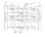
- the light detection substrate 37 includes an imaging surface 39 in which a plurality of pixels 38 that accumulate charges corresponding to the X-ray dose are arranged on a glass substrate (not shown).
- the plurality of pixels 38 are two-dimensionally arranged in a matrix of n rows (X direction) ⁇ m columns (Y direction) at a predetermined pitch.
- n and m are integers of 2 or more, for example, n and m ⁇ 1024.
- the arrangement of the pixels 38 may not be a square arrangement as in this example, but may be a honeycomb arrangement.
- the pixel 38 includes a photodiode 40 that is a photoelectric conversion element that generates and accumulates charges (electron-hole pairs) by incidence of visible light, and a TFT 41 that is a switching element.
- the photodiode 40 has a structure in which a semiconductor layer (for example, a PIN (p-intrinsic-n) type) that generates electric charges and an upper electrode and a lower electrode are arranged above and below the semiconductor layer.
- the photodiode 40 has a TFT 41 connected to the lower electrode and a bias line connected to the upper electrode. Bias lines are provided for the number of rows of pixels 38 (n rows) and connected to a single bus.
- the bus is connected to a bias power source.
- a bias voltage is applied from the bias power source to the upper electrode of the photodiode 40 through the bus line and its bias line.
- An electric field is generated in the semiconductor layer by application of the bias voltage.
- the photodiode 40 is used in a reverse bias state. Among the charges (electron-hole pairs) generated in the semiconductor layer by photoelectric conversion, the electrons move to the upper electrode and are absorbed by the bias line, and the holes move to the lower electrode and are collected as signal charges.
- the TFT 41 has a gate electrode connected to the scanning line 42, a source electrode connected to the signal line 43, and a drain electrode connected to the lower electrode of the photodiode 40.
- the scanning lines 42 extend in the X direction along the row direction of the pixels 38 and are arranged at a predetermined pitch in the Y direction along the column direction of the pixels 38.
- the signal lines 43 extend in the Y direction and are arranged at a predetermined pitch in the X direction.
- the scanning lines 42 and the signal lines 43 are wired in a grid pattern within the imaging surface 39, and the pixels 38 are provided corresponding to the intersections of the scanning lines 42 and the signal lines 43.
- the scanning lines 42 are provided for the number of rows of the pixels 38 (for n rows), and the signal lines 43 are provided for the number of columns of the pixels 38 (for m columns).
- the scanning line 42 is connected to the gate driver 44, and the signal line 43 is connected to the signal processing circuit 45.
- the pixel 38 is divided into a normal pixel 38a and a detection pixel 38b.
- the normal pixel 38a is used for generating an X-ray image.
- the detection pixel 38b functions as an X-ray detection unit for detecting a dose per unit time (X-ray intensity) of X-rays reaching the imaging surface 39, and for X-ray irradiation start determination and AEC. Used.
- the TFT 41 of the detection pixel 38 b is short-circuited by connecting the source electrode and the drain electrode by a short-circuit line 55.
- the TFT 41 of the normal pixel 38a is not short-circuited.
- the detection pixel 38b is hatched to be distinguished from the normal pixel 38a.
- the TFT 41 of the detection pixel 38b is always on regardless of the voltage applied to the gate electrode because the source and drain electrodes are short-circuited. For this reason, the charge collected on the lower electrode of the photodiode 40 flows out to the signal line 43 via the short-circuit line 55. On the other hand, in the normal pixel 38 a, the charge is read out to the signal line 43 in accordance with the voltage applied to the gate electrode of the TFT 41.
- the detection pixel 38b is different from the detection pixel 38b only in that the source and drain electrodes of the TFT 41 are short-circuited.
- Other basic configurations such as the photodiode 40 are the same as those of the normal pixel 38a. Therefore, both can be formed by substantially the same manufacturing process.
- the detection pixel 38b can be configured by directly connecting the photodiode 40 to the signal line 43 without providing the TFT 41, but in this embodiment, the structure and characteristics of the normal pixel 38a and the detection pixel 38b are included. In order not to make a difference between them, the TFT 41 is provided similarly to the normal pixel 38a, and the source and drain electrodes are short-circuited by the short-circuit line 55 to form the detection pixel 38b.
- the number of detection pixels 38b is, for example, about 1 / million to several hundredths of the number of all pixels 38.
- the signal line 43 is divided into a second signal line 43a to which a plurality of detection pixels 38b are connected and a second signal line 43b to which only the normal pixels 38a are connected.
- the second signal lines 43a are periodically provided with a plurality of second signal lines 43b interposed therebetween.
- the detection pixels 38 b are arranged so as to be evenly scattered on the imaging surface 39. For this reason, even when the X-ray irradiation range is limited to a part of the imaging surface 39, X-rays can be detected by any of the detection pixels 38b.
- the position of the detection pixel 38 b is known when the detection panel 30 is manufactured.
- the XY coordinates of all the detection pixels 38 b are stored in the internal memory of the control unit 32 in advance.
- the detection pixels 38b may be arranged in a concentrated manner locally, and the arrangement of the detection pixels 38b can be changed as appropriate. For example, in a mammography apparatus that takes an image of the breast, the detection pixels 38b may be arranged concentrated on the chest wall side.
- the control board 31 is provided with a gate driver 44, a signal processing circuit 45, a memory 51, an irradiation start determination unit 52, an AEC unit 53, and a control unit 32 for controlling them.
- the control unit 32 drives the TFT 41 through the gate driver 44, thereby accumulating a signal charge corresponding to the X-ray dose in the normal pixel 38a, and an image reading (main reading) operation for reading the signal charge from the normal pixel 38a.
- the detection panel 30 is caused to perform a pixel reset (empty reading) operation for reading out and resetting (discarding) dark charges from the normal pixels 38a.
- the gate driver 44 does not apply a gate pulse to any of the scanning lines 42, so the TFT 41 of the normal pixel 38a is turned off, and signal charges are accumulated in the normal pixel 38a during that time.
- gate pulses G1 to Gn for simultaneously driving the TFTs 41 in the same row from the gate driver 44 are sequentially generated at a predetermined interval ⁇ t (see FIG. 5), and the scanning lines 42 are sequentially supplied row by row.
- the TFT 41 of the normal pixel 38a connected to each scanning line 42 is turned on by one row.
- the time during which the TFT 41 is turned on is defined by the pulse width of the gate pulse, and the TFT 41 returns to the off state when the time defined by the pulse width has elapsed.
- the charge accumulated in the normal pixel 38 a is read out to the signal line 43 and input to the signal processing circuit 45 when the TFT 41 is turned on.
- the signal processing circuit 45 includes an integrating amplifier 46, a CDS circuit (CDS: Correlated Double Sampling) 47, a multiplexer (MUX) 48, an A / D converter (A / D) 49, and the like.
- the integrating amplifier 46 is individually connected to each signal line 43.
- the integrating amplifier 46 includes an operational amplifier 46a, a capacitor 46b connected between the input and output terminals of the operational amplifier 46a, and an amplifier reset switch 46c connected in parallel to the capacitor 46b.
- the signal line 43 is connected to one input terminal of the operational amplifier 46a.
- the other input terminal of the operational amplifier 46a is connected to the ground (GND).
- the integrating amplifier 46 accumulates the charges input from the signal line 43 by accumulating them in the capacitor 46b, converts them into analog voltage signals V1 to Vm corresponding to the accumulated values, and outputs them.
- the unpreset switch 46c is driven and controlled by the control unit 32. By turning on the unpreset switch 46c, the charge accumulated in the capacitor 46b is reset (discarded).
- the MUX 48 is connected to the output terminal of the operational amplifier 46a in each column via the amplifier 50 and the CDS 47. An A / D 49 is connected to the output side of the MUX 48.
- the amplifier 50 amplifies the analog voltage signal output from the integrating amplifier 46 with a predetermined gain value.
- the gain value is set by the control unit 32 based on the shooting conditions from the console 14.
- the CDS 47 is connected to the output terminal of the amplifier 50, performs correlated double sampling on the voltage signal amplified by the amplifier 50, removes reset noise of the integrating amplifier 46 from the voltage signal, and outputs the voltage signal. Hold for a predetermined period (sample hold).
- the CDS 47 has two sample and hold circuits (not shown) and one difference circuit (not shown).
- One sample and hold circuit samples and holds the voltage signal output from the amplifier 50, and the reset noise component of the integration amplifier 46 output from the amplifier 50 when the integration amplifier 46 is reset by the other sample and hold circuit. Sample and hold. By taking the difference between the two in the difference circuit, a voltage signal from which noise has been removed is obtained.
- the MUX 48 is connected to the output terminal of each CDS 47. Based on an operation control signal from a shift register (not shown), the MUX 48 selects the CDS 47 in the first column to the m-th column one by one in order.
- the voltage signals V1 to Vm output from the CDS 47 are serially input to the A / D 49.
- the A / D 49 converts the input voltage signals V1 to Vm into digital voltage signals and outputs them to the memory 51.
- An amplifier may be connected between the MUX 48 and the A / D 49.
- the control unit 32 drives the gate driver 44 and each part of the signal processing circuit 45 (integration amplifier 46, CDS 47, MUX 48, A / D 49) at a predetermined cycle.
- Gate pulses G1 to Gn are sequentially generated from the gate driver 44 to the scanning line 42 at a predetermined interval ⁇ t to select the scanning line 42 in order from the first row to the n-th row, and the result is output from the A / D 49.
- One row of voltage signals is sequentially stored in the memory 51.
- the memory 51 stores a voltage signal representing one X-ray image in association with the XY coordinates of each pixel 38.
- the voltage signal data is read from the memory 51 to the control unit 32, subjected to various image processing by the control unit 32, and then transmitted to the console 14 through the communication unit 33.
- an X-ray image of the subject is detected.
- a voltage signal read by the image reading operation is referred to as an image signal.
- the pixel reset operation is an operation for sweeping out dark charges generated in the normal pixel 38 a through the signal line 43.
- the pixel reset operation is performed by, for example, a sequential reset method in which the normal pixels 38a are reset line by line.
- the sequential reset method similarly to the image reading operation, gate pulses G1 to Gn are sequentially generated from the gate driver 44 to the scanning line 42 at a predetermined interval ⁇ t, and the TFTs 39 of the pixels 38 are turned on line by line. While the TFT 41 is on, dark charges flow from the normal pixel 38 a to the capacitor 46 b of the integrating amplifier 46 through the signal line 43.
- signal charges are not read out by the MUX 48, and the amplifier reset pulse RST is output from the control unit 32 in synchronization with the fall of each of the gate pulses G1 to Gn. 46c is turned on, the dark charge accumulated in the capacitor 46b is discharged, and the integrating amplifier 46 is reset.
- multiple rows of array pixels are grouped as a group, and the reset is performed sequentially within the group, and the dark charge of the number of rows in the group is simultaneously discharged.
- An all-pixel reset method that simultaneously sweeps out the dark charges may be used.
- the pixel reset operation can be speeded up by the parallel reset method or the all pixel reset method.
- the charge collected on the lower electrode of the photodiode 40 of the detection pixel 38b always flows out to the second signal line 43a via the short circuit line 55. Since a plurality of detection pixels 38b are connected to one second signal line 42a, the charges from the plurality of detection pixels 38b are added and flow into the capacitor 46b of the integration amplifier 46, and then to the capacitor 46b. Accumulated. That is, even when the normal pixel 38a in the same column has the TFT 41 turned off and the charge is being accumulated, the charge of the detection pixel 38b can be read out by driving each part of the signal processing circuit 45. It is.
- the control unit 32 stops the pixel reset operation when receiving the irradiation start request signal. Then, the signal processing circuit 45 starts the dose sampling operation. The dose sampling operation is performed for start determination processing by the irradiation start determination unit 52 and AEC by the AEC unit 53, as will be described later.
- the signal processing circuit 45 performs a dose sampling operation of reading out a voltage signal corresponding to the charge of the detection pixel 38b at the sampling period set by the control unit 32. Since the electric charge of the detection pixel 38b changes according to the amount of X-rays incident on the imaging surface 39, the voltage signal obtained by one sampling represents the dose per unit time of the X-rays reaching the imaging surface 39. To express. Hereinafter, the voltage signal read out in this dose sampling operation is referred to as a dose signal. Thus, the signal processing circuit 45 functions as a dose sampling unit that samples a dose signal.
- the amplifier reset pulse RST is input from the control unit 32 to the amplifier reset switch 46c of the integrating amplifier 46 every time sampling is performed, and the accumulated charge is reset.
- a plurality of CDS circuits 47 are sequentially selected by the MUX 48 and the dose signal for one row is sampled as in the case of reading the image signal for one row of the image reading operation. Since the outputs of the plurality of detection pixels 38b distributed in the imaging surface 39 always flow out to the second signal line 42a, all the detection pixels 38b are included in the dose signal for one line read out in the dose sampling operation. Dose signals corresponding to are included.
- the memory 51 records the dose signal for one line.
- the control unit 32 is provided with a circuit (not shown) that performs various image processing such as offset correction, sensitivity correction, and defect correction on the X-ray image stored in the memory 51 by the image reading operation.
- the offset correction circuit removes offset noise caused by the dark current characteristics of each photodiode 40 by subtracting the offset correction image acquired by performing the image reading operation without irradiating the X-ray in pixel units from the X-ray image. To do.
- the sensitivity correction circuit is also called a gain correction circuit, and corrects variations in sensitivity of the photodiode 40 of each pixel 38, variations in output characteristics of the signal processing circuit 45, and the like.
- Sensitivity correction is performed based on sensitivity correction data generated based on an image obtained by subtracting the offset correction image from an image obtained by irradiating a predetermined dose of X-rays in the absence of a subject.
- Sensitivity correction data is a deviation from the reference value so that the output of each pixel is uniformly the same by multiplying the X-ray image after offset correction when a predetermined dose of X-rays is irradiated in the absence of a subject.
- the defect correction circuit linearly interpolates the pixel values of the defective pixels with the pixel values of the surrounding normal pixels based on the defective pixel information attached at the time of shipment.
- the defect correction circuit also treats the detection pixel 38b used for X-ray irradiation start determination and AEC as a defective pixel. Since the pixel value of the normal pixel 38a in the column of the second signal line 43a in which the detection pixel 38b is arranged is also affected by the output of the detection pixel 38b that always flows out, the defect correction circuit determines the pixel value of the detection pixel 38b and The pixel values of the normal pixels 38a in the column of the second signal lines 43a in which the detection pixels 38b are arranged are similarly interpolated.
- the offset correction image and the sensitivity correction data are acquired, for example, at the time of shipment of the electronic cassette 13, or are acquired by a manufacturer's service person at the time of regular maintenance or by an operator at the start time of the hospital, and are recorded in the internal memory of the control unit 32. And read out during correction.
- the various image processing circuits described above may be provided in the console 14 and various image processing may be performed by the console 14.
- the irradiation start determination unit 52 and the AEC unit 53 are driven and controlled by the control unit 32.
- the irradiation start determination unit 52 and the AEC unit 53 read the dose signal from the memory 51 every time the dose signal is sampled by the signal processing circuit 45 and the dose signal for one line is recorded in the memory 51.
- the irradiation start determination unit 52 and the AEC unit 53 first remove the dummy signal from the dose signal for one row read from the memory 51.
- the column of the second signal lines 43a in which the detection pixels 38b are provided is provided by sandwiching a plurality of columns of the second signal lines 43b in which the detection pixels 38b are not provided.
- This dose signal includes a dummy signal corresponding to the column of the second signal line 43b between the significant dose signals of the column of the second signal line 43a.
- the dummy signal is based on the leakage charge leaking from the normal pixel 38a and is almost zero.
- the irradiation start determination part 52 and the AEC part 53 perform a start determination process and AEC after removing a dummy signal which is meaningless as data. Instead of removing the dummy signal after reading the dose signal for one row from the memory 51, only the dose signal corresponding to the column of the second signal line 3a may be selected when reading from the memory 51.
- the irradiation start determination unit 52 determines whether or not the X-ray generator 2a actually starts X-ray irradiation based on the dose signal, more specifically, the X-ray is actually irradiated and the detection panel 30 is irradiated. A start determination process is performed to determine whether or not the detection panel 30 has detected X-rays. In the start determination process, the irradiation start determination unit 52 receives the irradiation start request start signal from the radiation source control device 11 and switches from the standby mode in which the detection panel 30 repeats the pixel reset operation to the imaging mode in which the accumulation operation starts. To begin.
- the irradiation start determination unit 52 detects all the detection pixels 38b or detection pixels existing in a specific region in the detection panel 30 (for example, a blank region where X-rays are directly irradiated without passing through the subject).
- the representative value of the dose signal from 38b is compared with a preset irradiation start threshold (see FIG. 5).
- the representative value of the dose signal is an average value, a maximum value, a mode value, or a total value.
- the irradiation start determining unit 52 determines that X-ray irradiation has actually started from the X-ray source 10 when the representative value of the dose signal exceeds the irradiation start threshold.
- the irradiation start determination unit 52 reads the current time when it is determined that the irradiation has started from a clock circuit (not shown), and records the read current time as the start time T0. Note that, as the start time T0, instead of the current time, a time that becomes a reference for the subsequent time measurement may be recorded.
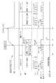
- the control unit 32 sets the sampling period of the dose signal to the same sampling period ⁇ t (second sampling period) as the generation interval ⁇ t of the gate pulses G1 to Gn. ). For this reason, a dose signal for one row is recorded in the memory 51 for each ⁇ t, and the dose signal and the irradiation start threshold value are compared for each ⁇ t.
- the control unit 32 switches the sampling period of the dose signal from ⁇ t to ⁇ T after the start time T0.
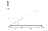
- the AEC unit 53 measures the cumulative dose based on the dose signal sampled at the sampling period ⁇ T during the X-ray irradiation. Then, based on the measured cumulative dose, the time when the cumulative dose reaches the target dose is predicted. The AEC unit 53 starts operation when the irradiation start determination unit 52 determines that X-ray irradiation has started. The AEC unit 53 measures the accumulated dose based on the dose signal sampled at the measurement time T1 when the sampling period ⁇ T has elapsed from the start time T0.
- the accumulated dose is measured based on a representative value of a dose signal from all the detection pixels 38b or from detection pixels 38b existing in a specific region (for example, a region of interest that is most noticeable at the time of diagnosis) in the detection panel 30.
- the representative value of the dose signal is an average value, maximum value, mode value, or total value of the dose signal.
- the predicted time when the accumulated dose of X-rays reaches the target dose is predicted by linear extrapolation.
- an interpolation line representing the time change of the accumulated dose by connecting the origin and the measured dose S1, which is the accumulated dose measured at the measurement time T1, with the start time T0 as the origin. L1 is calculated. Since the start time T0 is a time when it is determined that the X-ray irradiation is started, the accumulated dose at the start time T0 can be regarded as almost zero. Then, the AEC unit 53 calculates an extrapolation line L2 that is a straight line obtained by extending the insertion line L1 after the measurement time T1, and predicts a time when the extrapolation line L2 reaches the irradiation stop threshold STH that is a target dose. Calculate as time TP. Further, a remaining time TR which is a difference between the predicted time TP and the measurement time T1 is obtained.
- the start time T0 is a time when the irradiation start determination unit 52 determines that the irradiation is started by comparing the dose signal with the irradiation start threshold, and is slightly delayed from the time when the X-ray is actually started. Therefore, strictly speaking, the cumulative dose at the start time T0 is not completely zero. Therefore, when the prediction calculation is performed more accurately, the accumulated dose at the start time T0 is not regarded as zero, but is the accumulated dose at the start time T0 based on the dose signal used for comparison with the irradiation start threshold.
- the measurement dose S0 may be measured.
- the AEC unit 53 sets the accumulated dose at the start time T0 as the measured dose S0, and calculates the predicted time T2 based on the measured dose S0 and the measured dose S1 at the measurement time T1.
- the sampling period ⁇ T (first sampling period) is a time period from the start time T0 to the measurement time T1 after the start time T0, and is an accumulation period in which the charge output from the detection pixel 38b in the integration amplifier 46 is accumulated.
- the AEC unit 53 can measure the measurement dose S1 at the measurement time T1 based on the dose signal output by the signal processing circuit 45 in one sampling. If the sampling period ⁇ T is too short, the reliability of the prediction calculation in the AEC unit 53 decreases. This is because the shorter the accumulation period for accumulating charge, the lower the S / N ratio of the obtained dose signal. On the other hand, if the sampling period ⁇ T is too long, the cumulative dose may reach the target dose during that time. Therefore, the sampling period ⁇ T is set to an appropriate value considering the reliability of the prediction calculation and the irradiation time.
- the AEC unit 53 has a timer in which the remaining time TR calculated by prediction is set, and when the timer counts that the remaining time TR has become zero, an irradiation stop signal is sent to the communication unit 33 via the control unit 32. Is output.
- the communication unit 33 is provided with an irradiation signal I / F 54 (see FIG. 4).
- the irradiation signal I / F 25 of the radiation source control device 11 is wired or wirelessly connected to the irradiation signal I / F 54.
- the irradiation signal I / F 54 receives an irradiation start request signal, transmits an irradiation permission signal in response to the irradiation start request signal, and transmits an irradiation stop signal output from the AEC unit 53.
- you may transmit the information of estimated time TP instead of an irradiation stop signal to the radiation source control apparatus 11 as an AEC signal.
- the remaining time TR may be transmitted to the radiation source control device 11 as an AEC signal.
- the radiation source control device 11 When receiving the predicted time TP and the remaining time TR, the radiation source control device 11 counts down the remaining time TR with a time count or timer of the predicted time TR, and when the predicted time TP is reached or when the remaining time TR is X-ray irradiation is stopped when zero is reached.
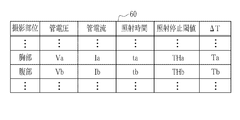
- an imaging condition table 60 is stored in the storage device 14c of the console 14.
- the imaging conditions include information on the subject such as the imaging region, the sex of the subject, age, etc. (only the imaging region is shown in FIG. 7), X-ray irradiation conditions including tube voltage, tube current, and irradiation time, and electronic cassette 12.
- An irradiation stop threshold value used when performing AEC, a sampling period ⁇ T at the time of AEC, and the like are stored. Note that the same value is set as the irradiation start threshold regardless of the imaging region.
- the imaging condition table 60 correspondences between imaging regions such as the chest and abdomen and irradiation conditions and the like corresponding to the imaging regions are recorded. Irradiation conditions and the like corresponding to the imaging region designated by the input device 14a are recorded. It is read from the storage device 14c and displayed on the operation screen of the display 14b. Each value of the irradiation condition read from the imaging condition table 60 can be finely adjusted according to the sex, age, and body thickness of the subject. The operator confirms the contents of the inspection order on the display 14b, and inputs imaging conditions corresponding to the contents on the input device 14a. Information on the set shooting conditions is transmitted from the console 14 to the electronic cassette 13. The irradiation conditions of the radiation source controller 11 are set manually by referring to the irradiation conditions set by the operator using the console 14.
- the irradiation time set on the console 14 does not mean that the X-ray irradiation is stopped during the irradiation time, but is merely a function corresponding to the imaging region and the body thickness of the subject. Recommended value. Further, in the imaging condition table 60 of this example, the tube current and the irradiation time are individually recorded. However, since the total amount of X-ray irradiation dose is determined by the product of the tube current and the irradiation time, The value of the current irradiation time product (mAs value) may be recorded.
- the operation of the above configuration will be described with reference to the timing chart of FIG. 5 and the flowchart of FIG.
- the subject is placed at a predetermined position in front of the standing imaging table 15 or placed on the supine imaging table 16, and the standing or lying imaging table 15 is placed.
- 16 is adjusted to adjust the height and horizontal position of the electronic cassette 13 used for imaging to match the imaging location of the subject.
- the height, horizontal position, and size of the irradiation field of the X-ray source 10 are adjusted according to the position of the electronic cassette 13 and the size of the imaging region.
- the electronic cassette 13 to be used is selected on the console 14, and shooting conditions are set on the console 14.
- the same X-ray irradiation conditions as those set for the console 14 are set in the radiation source control device 11.
- the photographing conditions set on the console 14 are transmitted to the electronic cassette 13.
- a warm-up start signal is input to the radiation source control device 11, and the warm-up of the X-ray source 10 is started. Further, an irradiation start request signal is transmitted from the radiation source control device 11 to the electronic cassette 13.
- the electronic cassette 13 waits for imaging conditions from the console 14 in a sleep mode in which only the communication unit 33 is driven, for example.
- the detection panel 30 starts a pixel reset operation and shifts from the sleep mode to the standby mode (step S110).
- a gate pulse is emitted from the gate driver 44, and unnecessary charge of the normal pixels 38a for one row is read to the signal line 43, and discarded by the integrating amplifier 46 is repeatedly performed at a predetermined cycle.
- the electronic cassette 13 waits for an irradiation signal I / F 54 for an irradiation start request signal from the irradiation signal I / F 25.
- a dose sampling operation for irradiation start determination is started at the sampling period ⁇ t (step S140).
- the charge of the detection pixel 38 b flows out to the signal line 43 and is accumulated in the integrating amplifier 46 because the source electrode and the drain electrode of the TFT 41 are short-circuited.
- a dose signal corresponding to the charge of the detection pixel 38b accumulated in the integrating amplifier 46 is sampled.
- the charge of the detection pixel 38b accumulated in the integration amplifier 46 is reset every sampling.
- a plurality of CDS circuits 47 are sequentially selected by the MUX 48 and a dose signal for one row is recorded in the memory 51.
- an irradiation start signal is input to the radiation source control device 11 and X-ray irradiation is started from the X-ray source 10.
- the irradiation start determination unit 52 starts the start determination process based on the dose signal (step S150).
- the dose signal for one line recorded in the memory 51 is read to the irradiation start determination unit 52 every sampling.
- the irradiation start determination unit 52 calculates a representative value of the dose signal for each sampling, and compares this with a preset irradiation start threshold value. There is a time lag from the reception time T00 when the irradiation start request signal is received until the X-rays are actually irradiated, and the dose signal during that time becomes a very low value based on the dark charge generated in the detection pixel 38b.
- the detection pixel 38b responds and the amount of generated charges increases, and the dose signal S0 at that time also becomes a high value and exceeds the irradiation start threshold. In this way, the irradiation start determination unit 52 determines that X-ray irradiation has started (YES in step S160, start time T0).
- the control unit 32 changes the sampling period of the dose signal from ⁇ t to ⁇ T, and the dose sampling operation is subsequently performed (step S170).
- the control unit 32 resets the integration amplifier 46, Immediately, the integration amplifier 46 starts accumulation of charges from the detection pixel 38b input from the signal line 43.
- the control unit 32 samples the dose signal corresponding to the accumulated charge of the integrating amplifier 46 at the measurement time T1 after the preset sampling period ⁇ T has elapsed from the start time T0.
- the dose signal is recorded in the memory 51 (S180). After outputting the dose signal, the detection panel 30 ends the dose sampling operation. The accumulation operation continues.
- the AEC unit 53 Since the dose signal sampled at the measurement time T1 is a signal representing the accumulated dose S1 from the start time T0 to the measurement time T1, the AEC unit 53 measures the accumulated dose S1 based on the dose signal. The AEC unit 53 calculates the predicted time T2 at which the extrapolation line L2, which is an extension of the interpolation line L connecting the accumulated dose S1 at the measurement time T1 with the start time T0 as the origin, reaches the irradiation stop threshold value STH. Then, the remaining time TR, which is the difference between the predicted time TP and the measurement time T1, is calculated (step S190).
- the remaining time TR is set in the timer of the AEC unit 53.
- an irradiation stop signal is output from the AEC unit 53 (step S210).
- an irradiation stop signal is transmitted from the irradiation signal I / F 54 toward the irradiation signal I / F 25.
- the X-ray source 10 stops the X-ray irradiation.
- the irradiation stop signal is not received by the radiation source control device 11
- the X-ray irradiation is stopped after the irradiation time set in the radiation source control device 11 has elapsed.
- the control unit 32 shifts the operation of the detection panel 30 from the accumulation operation to the image reading operation (S220).
- the image reading operation a gate pulse is emitted from the gate driver 44, the signal charge of the normal pixels 38a for one row is read to the signal line 43, and the image signal for one row corresponding to the signal charge is extracted from the integration amplifier 46.
- the operation recorded in the memory 51 after A / D conversion is repeated at a predetermined cycle. As a result, an image signal representing one X-ray image is recorded in the memory 51.
- the detection panel 30 returns to the standby mode in which the pixel reset operation is performed.
- a wave tail occurs without the dose becoming zero immediately after the irradiation stop signal is output.
- the storage operation is shifted to the image reading operation after a predetermined time has elapsed since the irradiation stop signal was transmitted.
- the X-ray image output to the memory 51 by the image reading operation is subjected to various image processing by various image processing circuits of the control unit 32, and then wired or wirelessly transmitted to the console 14 via the communication unit 33, and the display 14b. Is displayed for diagnosis. This completes one X-ray imaging.
- the irradiation start determination unit 52 determines that X-ray irradiation has actually started, detects the start time T0, and the AEC unit 53 detects the start time T0 to the measurement time T1.
- the measurement dose S1 that is the cumulative dose until is measured, and the prediction time TP at which the cumulative dose from the start time T0 reaches the irradiation stop threshold value STH is calculated based on the measurement dose S1. Can be done in time.
- the irradiation start determination unit 52 detects the start time T0 at which the accumulated dose is almost zero.
- the cumulative dose (measured dose S1) at one time after the start time T0 is measured, the time change of the cumulative dose with the start time T0 as the origin can be known, so the predicted time TP when the cumulative dose reaches the irradiation stop threshold value STH. Can be calculated.
- the accumulated dose after the start time T0 needs to be measured at least once, so that the predicted time TP can be calculated in a short time.
- the present invention can calculate the predicted time TP by measuring the accumulated dose at least once, the conventional technology (Japanese Patent Application Laid-Open No. 2010-075556) that requires two measurements during irradiation is possible. In comparison, sufficient time can be secured for obtaining a reliable dose signal used for measurement. Further, since the predicted time TP can be calculated by measuring the accumulated dose at least once, it is possible to cope with low-dose imaging with a short irradiation time.
- the time lag from receiving a synchronization signal such as an irradiation start request signal to actually irradiating X-rays varies depending on imaging conditions and the like.
- Japanese Patent Application Laid-Open No. 2010-075556 Japanese Patent Application Laid-Open No. 2010-075556
- the present invention detects the start time T0.
- the measurement time can be brought closer to the start time T0, so that the predicted time can be calculated in a short time.
- the present invention is less likely to fall into this situation than in the prior art.
- the period from the start time T0 to the measurement time T1 is set as the sampling period ⁇ T, and the dose signal representing the measurement dose S1 is acquired by one sampling, so the dose obtained by multiple samplings Compared with the case where the measured dose S1 is measured by adding the signals, a dose signal with a high S / N ratio can be obtained because the sampling period is longer. Therefore, the reliability of the predicted time T2 is also high.
- the dose signal is sampled at a sampling period ⁇ t shorter than the sampling period ⁇ T until the irradiation start determination unit 52 determines that the irradiation has started, and after the start determination time T0, the sampling period ⁇ T. Has been changed.
- the dose signal is sampled at a short interval, so that a quick irradiation start determination can be made.
- the sampling period becomes longer and a dose signal with a high S / N ratio is obtained, so that the reliability of the predicted time T2 can be ensured.
- the detection pixel 38b also serves as an X-ray irradiation start determination and AEC X-ray detection unit, the cost is lower than when the X-ray detection unit is separately provided for irradiation start determination and AEC. Can be suppressed.
- the detection pixel 38b is a form using a part of the pixel 38, the cost can be suppressed lower than the case where the X-ray detection unit is provided separately from the detection panel 30. Furthermore, by adopting a form in which the detection pixel 38b uses a part of the pixel 38, the dose sampling unit can be shared by the signal processing circuit 45 for reading out the image signal, and the cost can be kept low in this respect. Can do.
- the detection pixel 38b in which the source electrode and drain electrode of the TFT 41 are short-circuited is illustrated, but a pixel in which the photodiode 41 is not directly connected to the signal line 43 without the TFT 41 itself may be used as the detection pixel.
- a pixel to which a TFT 73 driven by a scanning line 71 and a gate driver 72 other than the scanning line 42 and the gate driver 44 for driving the TFT 41 is connected in addition to the TFT 41.
- 74 may be a detection pixel.
- the scanning line 71 is provided in parallel with the scanning line 42 in the row where the detection pixel 74 is located. Each scanning line 71 is connected to one bus 75 before the gate driver 72, and the bus 75 is connected to the gate driver 72.
- the gate pulse g1 is applied from the gate driver 72 to the bus 75, all the TFTs 73 are turned on, and the charge generated in the detection pixel 74 flows to the capacitor 46b of the integrating amplifier 46 through the second signal line 43a.
- the gate driver 72 can be driven independently of the gate driver 44 and can read out the electric charge generated in the detection pixel 74 even when the TFT 41 is in the off state and the normal pixel 38a is performing the accumulation operation.
- the detection pixel 74 may be only the TFT 73 without the TFT 41.
- the gate pulse g1 is continuously applied from the gate driver 72 to the bus 75 to turn on the TFT 73, and the charge generated in the detection pixel 74 is converted into the second signal. It flows into the capacitor 46b of the integrating amplifier 46 through the line 43a.
- the dose signal corresponding to the charge generated in the detection pixel 74 is sampled at the same sampling period as the generation interval ⁇ t of the gate pulses G1 to Gn.
- the dose signal exceeds the irradiation start threshold and the irradiation start determination unit 52 determines that X-ray irradiation has actually started (start time T0)
- the output of the gate pulse g1 is stopped and the detection pixel 74 is stored. And This state is kept until the measurement time T1 after the sampling period ⁇ T has elapsed.
- the gate pulse g1 is again applied, and the charge generated in the detection pixel 74 during the sampling period ⁇ T is caused to flow into the capacitor 46b of the integration amplifier 46, and a dose signal based on this is output to the AEC unit 53. Subsequent processing is the same as that in the above embodiment, and thus description thereof is omitted.
- each bus can be read and each scan can be performed in the same manner as the gate driver 44.
- a configuration in which a gate pulse is applied to the line 71 may be employed.
- a plurality of adjacent scanning lines 71 may be combined into one group by the bus 91 and a gate pulse may be applied from the gate driver 92 to the bus 91 of each group.
- gate pulses g1 to g8 are applied to eight groups of buses 91 obtained by dividing the imaging surface 39 into eight equal parts is illustrated.
- only the gate pulse g1 is given at the time of the irradiation start determination and the dose signal is selectively sampled from the upper end group, or only the gate pulses g4 and g5 are given at the center at the time of AEC. It is possible to change the region where the dose signal is sampled according to the application, such as sampling the dose signal selectively from the group.
- pre-imaging may be performed in which a subject is irradiated with a low-dose X-ray, and a group for sampling dose signals at the time of AEC may be determined based on the result of pre-imaging.
- gate pulses g1 to g8 are sequentially generated to read out the charge of the detection pixel 74 and sample the dose signal. Then, for example, the average value of the dose signal is obtained for each block 93 obtained by dividing the imaging surface 39 into eight equal parts vertically and horizontally, and a dose map 100 shown in FIG. 12 is created.
- the dose map 100 represents the magnitude of the dose of X-rays received by the detection panel 90 for each block 93, and the block 93 corresponding to the blank region where the X-rays are directly irradiated without passing through the subject is dark hatched.
- the value becomes large as indicated by, and the value of the block 93 corresponding to the region irradiated with X-rays transmitted through the portion where the body thickness of the subject is relatively thick becomes small as indicated by white.
- the block 93 corresponding to the boundary between the blank region and the subject or the region where the subject is relatively thin has an intermediate value as shown by thin hatching.
- the accumulated dose (measured dose S1) is measured once after the start time T0 and the predicted time T2 is calculated.
- the accumulated dose is measured a plurality of times. Also good.
- the present invention detects the start time T0, so that the first measurement time T1 is set to the start time T0 as compared with the prior art (Japanese Patent Application Laid-Open No. 2010-075556). Since it can approach, the calculation of prediction time can be performed in a short time. Of course, in the case of measuring a plurality of times, it takes much time, and the effect of the present invention that the calculation of the predicted time TP is performed in a short time is diminished, so it is preferable to keep the measurement only twice or three times. .
- the measurement may normally be performed once, and the second measurement may be performed only when the first measurement dose S1 at the measurement time T1 is equal to or lower than a preset lower limit value.
- the lower limit value is, for example, a value at which the accuracy of the prediction calculation at the prediction time T2 exceeds the allowable range when the measured dose S1 is less than that.
- the second measurement is performed at the measurement time T2 when the sampling period ⁇ T has elapsed from the measurement time T1. If the second measurement is necessary, the dose signal is sampled at the measurement time T1, and then accumulation is continued without resetting the integrating amplifier 50.
- the first and second measurement results may be taken in, or only the second measurement result may be used.
- the predicted time TP based on the three measured doses S1 and S2 at the measurement times T1 and T2 and the three accumulated doses at the start time T0. Is calculated.
- the measurement dose S1 is discarded as an erroneous detection, and the predicted time TP is calculated based on two points excluding the measurement dose S1.
- the prediction time TP can be calculated in a short time.
- the accuracy of the prediction calculation at the predicted time T2 is achieved. Can be increased.
- the detection pixel 38b different from the normal pixel 38a is used as the X-ray detection unit.
- the detection pixel 38b is not provided in the detection panel, and the normal pixel 38a is used as the X-ray detection unit. May be used.
- the normal pixel 38a even when the TFT is turned off, a very small amount of leakage charge leaks to the signal line. The amount of leakage charge increases in accordance with the charge accumulation amount of the normal pixel 38a (corresponding to the incident amount of X-rays). Therefore, if the leak charge flowing in the signal line is accumulated by the integrating amplifier, the dose signal can be sampled, and the sampled dose signal can be used for irradiation start determination and AEC. Further, in the detection panel, an X-ray detection unit dedicated to irradiation start determination and AEC may be provided between the pixels 38 separately from the pixels 38.
- the dose signal may be sampled based on the current of the bias line connected to a specific pixel by utilizing the current based on the charge generated in the pixel flowing in the bias line that supplies the bias voltage to each pixel.
- the current detector that detects the current of the bias line is the X-ray detector.
- a dose sampling unit for integrating the current detected by the current detection unit is provided to sample the dose signal.
- the present invention is also effective when an X-ray detection unit such as an ion chamber (ionization chamber) that is conventionally known and separate from the detection panel is used.
- the console 14 and the electronic cassette 13 are separate from each other.
- the radiation source control device 11 and the console 14 may be integrated.
- the present invention is not limited to an electronic cassette that is a portable X-ray image detection device, and may be applied to an X-ray image detection device that is installed on an imaging table.
- CMOS Complementary Metal Metal Oxide Semiconductor
- CMOS Complementary Metal Metal Oxide Semiconductor
- the present invention can be applied not only to X-rays but also to imaging systems that use other radiation such as ⁇ rays.
Landscapes
- Health & Medical Sciences (AREA)
- Life Sciences & Earth Sciences (AREA)
- Engineering & Computer Science (AREA)
- Physics & Mathematics (AREA)
- General Health & Medical Sciences (AREA)
- High Energy & Nuclear Physics (AREA)
- General Physics & Mathematics (AREA)
- Molecular Biology (AREA)
- Medical Informatics (AREA)
- Pathology (AREA)
- Signal Processing (AREA)
- Multimedia (AREA)
- Spectroscopy & Molecular Physics (AREA)
- Analytical Chemistry (AREA)
- Heart & Thoracic Surgery (AREA)
- Biochemistry (AREA)
- Biophysics (AREA)
- Chemical & Material Sciences (AREA)
- Nuclear Medicine, Radiotherapy & Molecular Imaging (AREA)
- Optics & Photonics (AREA)
- Radiology & Medical Imaging (AREA)
- Biomedical Technology (AREA)
- Immunology (AREA)
- Surgery (AREA)
- Animal Behavior & Ethology (AREA)
- Public Health (AREA)
- Veterinary Medicine (AREA)
- Toxicology (AREA)
- Apparatus For Radiation Diagnosis (AREA)
- Measurement Of Radiation (AREA)
Description
本発明は、自動露出制御機能をもつ放射線画像検出装置およびその作動方法、並びに放射線撮影システムに関する。
医療分野において、放射線、例えばX線を利用したX線撮影システムが知られている。X線撮影システムは、X線を発生するX線発生装置と、X線を受けてX線画像を撮影するX線撮影装置とを備えている。X線発生装置は、X線を被写体(患者)に向けて照射するX線源、およびX線源の駆動を制御する線源制御装置を有している。X線撮影装置は、被写体を透過したX線に基づくX線画像を検出するX線画像検出装置、およびX線画像検出装置の駆動制御やX線画像の保存、表示を行うコンソールを有している。
X線画像検出装置は、X線画像を電気信号として検出する検出パネル(フラットパネルディテクタ(FPD;flat panel detector)とも呼ばれる)と、制御基板とを有している。検出パネルには、X線の線量に応じた信号電荷を蓄積する画素が二次元状に配列されている。制御基板は信号処理回路と制御部とを有する。信号処理回路は、TFT(Thin-Film Transistor)等のスイッチング素子を介して画素から行単位で読み出した信号電荷を蓄積して電圧信号に変換する積分アンプを有し、X線画像を構成する画像信号を出力する。
制御部は、画素に蓄積される電荷を掃き出す画素リセット動作と、全画素のスイッチング素子をオフ状態にして信号電荷を画素に蓄積させる蓄積動作と、蓄積動作終了後に、画素の先頭行から最終行まで一行ずつ信号電荷を読み出して一画面分のX線画像を出力する画像読み出し動作の三つの動作を検出パネルに実行させる。画像読み出し動作においては、信号電荷に基づく一行分の画像信号が出力される毎に、積分アンプに蓄積された信号電荷がリセット(破棄)され、次の行の信号電荷の蓄積に備えられる。
画素リセット動作は、X線画像へのノイズの影響を最小にするために、X線の非照射時にも発生する暗電荷や前回の撮影の残留電荷等による画素の不要蓄積電荷を掃き出す動作である。制御部は、この画素リセット動作をX線の照射開始前に繰り返し検出パネルに行わせる。したがってX線画像検出装置では、X線発生装置によるX線の照射開始タイミングと、画素リセット動作を終了して蓄積動作を開始するタイミングとの同期をとる必要がある。同期は、例えばX線発生装置とX線画像検出装置との間の同期信号の通信によって行われる。X線画像検出装置は同期信号をトリガに検出パネルが画素リセット動作から蓄積動作に移行する。
また、米国出願公開2012/049077号公報(日本出願特開2012-052896号公報)や日本出願特開2010-075556号公報に記載されているX線画像検出装置には、被写体への被曝量を抑えつつ適正な画質のX線画像を得るために、X線画像の露出を制御する自動露出制御(AEC;Automatic Exposure Control)部が設けられている。こうしたX線画像検出装置には、検出パネルに到達するX線を検出するX線検出部と、X線検出部の出力に基づいてX線の単位時間当たりの線量を表す線量信号をサンプリングする線量サンプリング部が設けられている。X線検出部は、例えば、検出パネル内の画素の一部を利用した形態であり、線量サンプリング部は、画素から信号電荷を読み出す信号処理回路が利用される。線量サンプリング部は、X線検出部が線量に応じて出力する電荷を蓄積し、蓄積した電荷に応じた電圧信号を線量信号として出力する積分アンプを有している。線量信号は、積分アンプが電荷を蓄積する期間に相当する所定のサンプリング周期でサンプリングされる。
AEC部は、線量信号に基づいてX線の累積線量を測定し、累積線量が予め設定した目標線量に達したか否かを判定する。X線画像検出装置は、累積線量が目標線量に達した時点で、蓄積動作から読み出し動作に移行する。
さらに、米国出願公開2012049077号公報に記載のX線画像検出装置は、線源制御装置との間に通信機能がない場合に対応するため、線量サンプリング部でサンプリングする線量信号に基づいてX線の照射が開始されたことを判定する照射開始判定機能を有している。このX線画像検出装置は、X線の照射が開始される前から線量サンプリング動作を開始し、サンプリングした線量信号と予め設定した照射開始閾値の比較結果に応じてX線の照射開始を判定し、照射開始と判定したときには蓄積動作を開始する。
また、日本出願特開2010-075556号公報には、累積線量が目標線量に達するまで累積線量を実測する代わりに、目標線量に達する前のある時点における累積線量である測定線量に基づいて、累積線量が目標線量に達すると予測される予測時刻を算出して、予測時刻となったときにX線の照射を停止させるAEC部を有するX線画像検出装置が記載されている。
予測時刻を算出する場合は、累積線量の時間変化を把握する必要がある。そのため、日本出願特開2010-075556号公報に記載のX線画像検出装置では、X線の照射中の二つの時点において累積線量を測定し、二つの時点の累積線量から直線外挿により累積線量が目標線量に達すると予測される予測時刻を算出している。具体的には図13に示すように、X線画像検出装置は、線量サンプリング部がサンプリングする線量信号に基づいて、線源制御装置からの同期信号を受信した受信時刻T00から所定時間経過した測定時刻T11における累積線量である測定線量S11を測定する。さらに測定時刻T11から所定時間経過した測定時刻T12における測定線量S12を測定する。そして、測定時刻T11における測定線量S11と、測定時刻T12における測定線量S12を結んだ内挿線L1を算出し、この内挿線L1を測定時刻T12以降に延伸した外挿線L2が目標線量である照射停止閾値STHに達する時刻を予測時刻TPとして算出している。
しかしながら、日本出願特開2010-075556号公報に記載されているX線画像検出装置のように予測時刻TPを算出する場合には、次のような問題があった。すなわち、X線発生装置は、X線はX線画像検出装置が同期信号を受けたと同時に照射される訳ではなく、受信時刻T00から実際にX線が照射される開始時刻T0まではタイムラグがある。このタイムラグは、オペレータの照射スイッチの操作タイミングの個人差、X線源の製品毎の仕様や個体差、あるいは撮影条件やX線源の経年劣化等に応じて異なる。タイムラグの期間はX線が照射されていないため、タイムラグの期間に一回目の累積線量を測定しても意味がない。
そのため、開始時刻T0以後のX線の照射中に確実に一回目の測定を行うためには、時刻T0からタイムラグを考慮して一回目の測定を行う必要がある。しかし、タイムラグは種々の条件によって変化するため、どの場合にも対応させるためには、最長のタイムラグを想定して測定時刻T11を決定する必要があるが、そうすると、一回目の測定時刻T11は開始時刻T0から大きく遅れることになる。予測時刻TPの算出には少なくとも二つの時点の累積線量が必要であるため、一回目の測定時刻T11が遅れた分、二回目の測定時刻T12も遅れるため、予測時刻TPの算出に時間が掛かるという問題が生じる。
また、測定時刻T11と測定時刻T12の間隔が短すぎると、予測時刻TPの算出精度の信頼性が低下するので、測定時刻T11と測定時刻T12の間隔はある程度空ける必要がある。測定時刻T11と測定時刻T12の間隔が大きいほど、予測時刻TPの算出に時間が掛かる。予測時刻TPの算出に時間が掛かると、最悪の場合、累積線量が目標線量に達して本来X線の照射を停止させる時刻が過ぎてしまうことにもなりかねず、その間被写体が無用な被曝に晒されるおそれがある。また、予測時刻の算出に時間が掛かると、X線の照射量を低く抑える低線量撮影のように、照射時間が短いX線撮影に対応することができないというおそれもある。
本発明は、累積線量を予測して自動露出制御を行う場合において、累積線量が目標線量に達する予測時刻の算出を短時間で行うことが可能な放射線画像検出装置およびその作動方法、並びに放射線撮影システムを提供することを目的とする。
上記目的を達成するために、本発明の放射線画像検出装置は、検出パネル、放射線検出部、線量サンプリング部、照射開始判定部、及び自動露出制御部とを備えている。検出パネルは、被写体の放射線画像を検出するための検出パネルであり、放射線発生装置から照射された放射線の線量に応じた画像信号を表す信号電荷を蓄積する画素が配列されている。放射線検出部は、検出パネルへ到達する放射線を検出する。線量サンプリング部は、放射線検出部の出力に基づいて放射線の単位時間当たりの線量を表す線量信号をサンプリングする。照射開始判定部は、線量信号と予め設定された照射開始閾値との比較結果に基づき、放射線発生装置による放射線の照射が開始されたか否かを判定する。自動露出制御部は、放射線画像の露出を制御する自動露出制御部であり、照射開始判定部が照射が開始されたと判定した開始時刻から所定時間経過した測定時刻までの放射線の累積線量である測定線量を線量信号に基づいて測定し、測定線量に基づき、開始時刻からの放射線の累積線量が、予め設定された目標線量である照射停止閾値に達すると予測される予測時刻を算出し、予測時刻に放射発生装置による放射線の照射を停止させる制御を行う。
自動露出制御部は、例えば、開始時刻を原点とし、原点と測定時刻における測定線量の点を結んだ、累積線量の時間変化を表す内挿線を算出し、内挿線の延長線である外挿線が照射停止閾値に達する時刻を予測時刻として算出する。
線量サンプリング部は、開始時刻以後の一回のサンプリングで測定線量を表す線量信号を出力することが好ましい。また、線量サンプリング部は、例えば、放射線検出部が出力する電荷を蓄積し、蓄積した電荷に応じた電圧信号を線量信号として出力する積分アンプを有している。
線量サンプリング部において、少なくとも開始時刻以後の線量信号をサンプリングする第1サンプリング周期は、開始時刻から測定時刻までの期間に設定されることが好ましい。線量サンプリング部は、照射開始判定部が、照射が開始されたと判定するまでの間、第1サンプリング周期よりも短い第2サンプリング周期で線量信号をサンプリングし、開始時刻以後、第1サンプリング周期に変更されることが好ましい。
自動露出制御部は、予測時刻を算出後、放射線発生装置による照射を停止させるための自動露出制御信号を出力することが好ましい。自動露出制御信号は、例えば、現在時刻が予測時刻に達したときに出力され、放射線発生装置に対して直ちに照射を停止させるための照射停止信号である。また、自動露出制御信号は、予測時刻、または予測時刻までの残時間でもよい。
自動露出制御部は、開始時刻以後、一回目の測定線量が下限値以下であった場合、測定線量を再度測定して予測時刻を算出してもよい。第1サンプリング周期は撮影部位に応じて変更可能であってもよい。
放射線検出部は、画素の少なくとも一部を利用した形態であることが好ましい。この場合には、例えば、画素には、放射線を受けて信号電荷を蓄積し、スイッチング素子の駆動に応じて信号電荷を信号線に出力する通常画素と、放射線検出部として利用され、通常画素とは独立に電荷を出力することが可能な検出画素とが含まれる。また、画素から信号電荷を読み出す信号処理回路を有しており、信号処理回路を、線量サンプリング部として機能させることが好ましい。
放射線画像検出装置は、例えば、検出パネルが可搬型の筐体に収納された電子カセッテである。
本発明の放射線画像検出装置の作動方法は、被写体の放射線画像を検出するために、放射線発生装置から照射された放射線の線量に応じた画像信号を表す信号電荷を蓄積する画素が配列された検出パネルを有する放射線画像検出装置の作動方法において、放射線検出ステップと、線量サンプリングステップと、照射開始判定ステップと、自動露出制御ステップとを備えている。放射線検出ステップは、検出パネルへ到達する放射線を放射線検出部で検出する。線量サンプリングステップは、放射線検出部の出力に基づいて放射線の単位時間当たりの線量を表す線量信号を線量サンプリング部でサンプリングする。照射開始判定ステップは、線量信号と予め設定された照射開始閾値との比較結果に基づき、放射線発生装置による放射線の照射が開始されたか否かを照射開始判定部で判定する。自動露出制御ステップは、放射線画像の露出を制御するステップであり、照射開始判定部が照射が開始されたと判定した開始時刻から所定時間経過した測定時刻までの放射線の累積線量である測定線量を線量信号に基づいて測定し、測定線量に基づき、開始時刻からの放射線の累積線量が、予め設定された目標線量である照射停止閾値に達すると予測される予測時刻を算出し、予測時刻に放射発生装置による放射線の照射を停止させる制御を行う。
放射線を照射する放射線発生装置と被写体の放射線画像を検出する放射線画像検出装置とを備えた放射線撮影システムにおいて、放射線画像検出装置は、検出パネル、放射線検出部、線量サンプリング部、照射開始判定部、及び自動露出制御部とを備えている。検出パネルは、被写体の放射線画像を検出するための検出パネルであり、放射線発生装置から照射された放射線の線量に応じた画像信号を表す信号電荷を蓄積する画素が配列されている。放射線検出部は、検出パネルへ到達する放射線を検出する。線量サンプリング部は、放射線検出部の出力に基づいて放射線の単位時間当たりの線量を表す線量信号をサンプリングする。照射開始判定部は、線量信号と予め設定された照射開始閾値との比較結果に基づき、放射線発生装置による放射線の照射が開始されたか否かを判定する。自動露出制御部は、放射線画像の露出を制御する自動露出制御部であり、照射開始判定部が照射が開始されたと判定した開始時刻から所定時間経過した測定時刻までの放射線の累積線量である測定線量を線量信号に基づいて測定し、測定線量に基づき、開始時刻からの放射線の累積線量が、予め設定された目標線量である照射停止閾値に達すると予測される予測時刻を算出し、予測時刻に放射発生装置による放射線の照射を停止させる制御を行う。
本発明によれば、放射線の照射が開始されたことを判定し、照射が開始されたと判定された開始時刻から測定時刻までの累積線量である測定線量を測定し、測定線量に基づいて、累積線量が目標線量に達する予測時刻の算出を行うから、予測時刻の算出を短時間で行うことが可能な放射線画像検出装置およびその作動方法、並びに放射線撮影システムを提供することができる。
図1において、X線撮影システム2は、X線発生装置2aとX線撮影装置2bとを備える。X線発生装置2aは、X線を放射するX線管を内蔵したX線源10と、X線源10の動作を制御する線源制御装置11と、X線の照射開始を指示するための照射スイッチ12とで構成されている。X線撮影装置2bは、可搬型のX線画像検出装置であり、被写体(患者)を透過したX線を検出してX線画像を出力する電子カセッテ13と、電子カセッテ13の動作制御やX線画像の保存や表示処理を担うコンソール14とで構成されている。後述するように、電子カセッテ13は、X線画像の露出を制御するために、X発生装置2aによるX線の照射を停止させるための自動露出制御信号(AEC信号)を出力するAEC機能を備えている。
電子カセッテ13は、被写体を立位姿勢で撮影するための立位撮影台15のホルダ15aや、被写体を臥位姿勢で撮影するための臥位撮影台16のホルダ16aに着脱自在に取り付けられる。電子カセッテ13は、前面34a(図3参照)がX線源10と対向する姿勢で各撮影台15、16のホルダ15a、16aに取り付けられる。被写体は、撮影部位がX線源10と電子カセッテ13との間に位置するよう、放射線技師などのオペレータによりポジショニングされる。X線源10は、線源移動装置(図示せず)により所望の方向および位置にセット可能であり、X線源10は立位撮影台15および臥位撮影台16で共用される。
コンソール14は、有線方式や無線方式により電子カセッテ13と通信可能に接続されている。コンソール14は、キーボードやマウスといった入力デバイス14a、ディスプレイ14b、ストレージデバイス14cなどを有する。入力デバイス14aは、撮影条件などのオペレータからの各種操作指示を受け付ける。ディスプレイ14bは、電子カセッテ13で検出したX線画像を表示する他、撮影条件の入力画面といった各種操作画面を表示する。ストレージデバイス14cは例えばハードディスクドライブであり、電子カセッテ13からのX線画像やX線撮影に必要な各種情報を記憶する。なお、X線画像は、コンソール14とネットワーク接続された画像蓄積サーバ(図示せず)に記憶することも可能である。
コンソール14は、被写体Hの性別、年齢、頭部、胸部、腹部、手、指といった撮影部位などの情報が含まれる検査オーダの入力を受け付けて、検査オーダをディスプレイ14bに表示する。検査オーダは、病院情報システム(HIS;Hospital Information System)や放射線情報システム(RIS;Radiology Information System)などの、被写体情報や放射線検査に係る検査情報を管理する外部システム(図示せず)から入力される。検査オーダは、入力デバイス14aを介してオペレータが手動入力することも可能である。
X線源10は、X線を放射するX線管と、X線管が放射するX線の照射野を限定する照射野限定器(コリメータともいう)とを有する。X線管には、熱電子を放出するフィラメントである陰極と、陰極から放出された熱電子が衝突してX線を放射する陽極(ターゲット)とを有している。照射野限定器は、例えば、X線を遮蔽する4枚の鉛板を四角形の各辺上に配置し、X線を透過させる四角形の照射開口が中央に形成されたものでる。各鉛板の位置を移動することで照射開口の大きさが変化し、照射野が変更される。
図2に示すように、線源制御装置11は、トランスによって入力電圧を昇圧して高圧の管電圧を発生し、高電圧ケーブルを通じてX線源10に供給する高電圧発生器20と、この高電圧発生器20の動作を制御する制御部21と、コンソール14との主要な情報、信号の送受信を媒介する通信I/F(InterFace)22とを備える。
制御部21には照射スイッチ12とメモリ23とタッチパネル24と照射信号I/F25が接続されている。照射スイッチ12は、オペレータによって操作される、例えば二段階押しのスイッチであり、一段階押しでX線源10のウォームアップを開始させるためのウォームアップ開始信号を発生し、二段階押しでX線源10に照射を開始させるための照射開始信号を発生する。これらの信号は信号ケーブルを通じて制御部21に入力される。
タッチパネル24は、オペレータがX線の照射条件を入力する際に操作される。照射条件には、X線源10が照射するX線のエネルギースペクトルを決める管電圧、単位時間当たりの照射量を決める管電流、およびX線の照射時間(管電圧を印可する時間)が含まれる。制御部21は、タッチパネル24から入力された照射条件に基づき、高電圧発生器20で発生する管電圧、管電流、およびX線の照射時間を制御する。
照射信号I/F25は、電子カセッテ13と有線または無線接続され、電子カセッテ13と同期信号の通信を行うためのI/Fである。同期信号は、X線発生装置2aによるX線の照射開始タイミングを同期させるための信号で、照射開始要求信号と照射許可信号がある。照射開始要求信号は、線源制御装置11がX線の照射を開始してよいか否かを電子カセッテ13に対して問い合わせるための同期信号であり、X線照射開始前に、照射信号I/F25から電子カセッテ13に向けて送信される。照射許可信号は、電子カセッテ13でX線の照射を受ける準備が完了したときに電子カセッテ13から線源制御装置11に向けて送信される同期信号である。
照射信号I/25で照射開始要求信号や照射許可信号の通信後直ちに、X線発生装置2aからX線の照射が開始される訳ではなく、照射許可信号の送信後、実際にX線が照射されるまでの間にはタイムラグがある(図5の受信時刻T00と開始時刻T0参照。このタイムラグは、オペレータの操作による個人差、X線源の製品毎の仕様や個体差、あるいは撮影条件やX線源の経年劣化等に応じて異なる。
また、照射信号I/F25は、電子カセッテ13から線源制御装置11に対して照射停止信号を送信する場合に利用される。照射停止信号は、電子カセッテ13のAEC機能を利用する場合において、X線発生装置2aによるX線の照射を直ちに停止させるためのAEC信号である。照射停止信号は、電子カセッテ13においてX線の累積線量が目標線量に達したと判定されたときに出力される。照射信号I/F25は、照射許可信号と照射停止信号を受信し、これら各信号を制御部21に入力する。
照射スイッチ12からウォームアップ開始信号が入力された場合、制御部21は、高電圧発生器20を動作させてX線源10のウォームアップを開始させる。具体的には、フィラメントに所定の電圧を印加させてフィラメントを予熱し、同時にターゲットの回転を開始させる。フィラメントの予熱が完了し、ターゲットが規定の回転数となったときにウォームアップが終了する。
制御部21は、照射信号I/F25で電子カセッテ13からの照射許可信号が受信され、かつ照射スイッチ12から照射開始信号を受けたときに高電圧発生器20を動作させてX線源10によるX線の照射を開始させる。照射信号I/F25で電子カセッテ13からの照射停止信号が受信された場合、制御部21は、高電圧発生器20を動作させてX線源10によるX線の照射を停止させる。
メモリ23は、管電圧、管電流、照射時間あるいは管電流照射時間積(いわゆるmAs値)等の照射条件を予め数種類格納している。照射条件はタッチパネル24を通じてオペレータにより手動で設定される。線源制御装置11は、設定された照射条件に応じてX線を照射する。ただし、線源制御装置11は、照射停止信号を受信した場合には、設定された照射時間あるいは管電流照射時間積以下であっても、X線の照射を停止する。また、AEC機能を使用する場合において、照射停止信号を受信する前にX線の照射が終了してしまうことがないように、線源制御装置11に設定される照射時間あるいは管電流照射時間積は、十分に大きい値が設定される。例えば、被写体への過大な被曝を避けるため線源制御装置11に撮影部位毎にプリセットされている安全規制上の最大照射時間が設定される。
制御部21はX線の照射が開始されたときに計時を開始するタイマー(図示せず)を有する。制御部21は、照射信号I/F25で照射停止信号が受信されないまま、タイマーで計時した時間が照射条件で設定された照射時間となった場合や、安全規制上、線源制御装置11に設定されている最大照射時間となった場合、照射信号I/F25で照射停止信号が受信された場合と同様にX線の照射を停止させる。
図3において、電子カセッテ13は、検出パネル30と、制御基板31と、バッテリ32と、通信部33と、これらを収容する可搬型の筐体34とを備えている。筐体34はほぼ矩形状で偏平な形状を有し、例えば導電性樹脂で形成されている。X線が入射する筐体34の前面34aには矩形状の開口が形成されており、開口には天板として透過板35が取り付けられている。透過板35は、軽量で剛性が高く、かつX線透過性が高いカーボン材料で形成されている。筐体34の平面サイズは、例えば、フイルムカセッテやIPカセッテ(CRカセッテとも呼ばれる)と同様の大きさ(国際規格ISO4090:2001に準拠した大きさ)である。このため、フイルムカセッテやIPカセッテ用の既存の撮影台にも取り付け可能である。
電子カセッテ13はX線撮影システム2が設置される撮影室一部屋に複数台、例えば立位撮影台15、臥位撮影台16用に二台配備され、二台の電子カセッテ13のうち使用する電子カセッテ13が撮影前にコンソール14で選択される。電子カセッテ13は、撮影台にセットする他に、被写体が仰臥するベッド上に置いたり被写体自身に持たせたりして単体で使用することもある。
バッテリ32は、電源回路(図示せず)を通じて電子カセッテ13の各部に電力を供給する。バッテリ32は、薄型の筐体34内に収まるよう比較的小型のものが使用される。バッテリ32は、筐体34内から外部に取り出し可能であり、専用の充電器(図示せず)にセットして充電することが可能である。なお、バッテリ32を電子カセッテ13に装着したまま無線給電可能な構成としてもよい。
通信部33は、線源制御装置11およびコンソール14と有線または無線接続され、線源制御装置11およびコンソール14との間で、前述の同期信号や撮影条件、X線画像などの各種情報を送受信する。通信部33は、バッテリ32の残量不足等で電子カセッテ13とコンソール14との無線通信が不可能になった場合にコンソール14と有線接続される。通信部33にコンソール14からのケーブルを接続した場合、コンソール14との有線通信が可能になる。この際、コンソール14からの電力を電源回路から電子カセッテ13の各部に給電してもよい。
検出パネル30は、シンチレータ(蛍光体)36と、光検出基板37とで構成される。シンチレータ36と光検出基板37は、X線の入射側からみてシンチレータ36、光検出基板37の順に積層されている。シンチレータ36は、CsI:Tl(タリウム賦活ヨウ化セシウム)やGOS(Gd2O2S:Tb、テルビウム賦活ガドリウムオキシサルファイド)などの蛍光体を有し、透過板35を介して入射したX線を可視光に変換して放出する。
光検出基板37は、シンチレータ36から放出された可視光を検出して電気信号に変換する。制御基板31は、光検出基板37の駆動を制御するとともに、光検出基板37から出力された電気信号に基づきX線画像を生成する。なお、シンチレータ36と光検出基板37は、本実施形態のようにX線の入射する側からみてシンチレータ36、光検出基板37の順に配置されるPSS(Penetration Side Sampling)方式でもよいし、逆に光検出基板37、シンチレータ36の順に配置されるISS(Irradiation Side sampling)方式でもよい。また、シンチレータ36を用いず、X線を直接電荷に変換する変換層(アモルファスセレン等)を用いた直接変換型の検出パネルを用いてもよい。
図4において、光検出基板37は、ガラス基板(図示せず)上にX線の線量に応じた電荷を蓄積する複数の画素38を配列してなる撮像面39を備えている。複数の画素38は、所定のピッチで二次元にn行(X方向)×m列(Y方向)、のマトリクス状に配列されている。n、mは2以上の整数であり、例えばn、m≒1024である。なお、画素38の配列は、本例のように正方配列でなくともよく、ハニカム配列でもよい。
画素38は、可視光の入射によって電荷(電子-正孔対)を発生してこれを蓄積する光電変換素子であるフォトダイオード40フォトダイオード40、およびスイッチング素子であるTFT41を備える。
フォトダイオード40は、電荷を発生する半導体層(例えばPIN(p-intrinsic-n)型)とその上下に上部電極および下部電極を配した構造を有している。フォトダイオード40は、下部電極にTFT41が接続され、上部電極にはバイアス線が接続されている。バイアス線は画素38の行数分(n行分)設けられて一本の母線に接続されている。母線はバイアス電源に繋がれている。母線とその子線のバイアス線を通じて、バイアス電源からフォトダイオード40の上部電極にバイアス電圧が印加される。バイアス電圧の印加により半導体層内に電界が生じる。フォトダイオード40は逆バイアスの状態で使用される。光電変換により半導体層内で発生した電荷(電子-正孔対)のうちの電子は、上部電極に移動してバイアス線に吸収され、正孔は、下部電極に移動して信号電荷として収集される。
TFT41は、ゲート電極が走査線42に、ソース電極が信号線43に、ドレイン電極がフォトダイオード40の下部電極にそれぞれ接続される。走査線42は、画素38の行方向に沿うX方向に延伸し、かつ画素38の列方向に沿うY方向に所定のピッチで配置されている。信号線43は、Y方向に延伸し、かつX方向に所定のピッチで配置されている。走査線42と信号線43は撮像面39内で格子状に配線されており、走査線42と信号線43の交差点に対応して画素38が設けられている。走査線42は画素38の行数分(n行分)、信号線43は画素38の列数分(m列分)それぞれ設けられている。走査線42はゲートドライバ44に接続され、信号線43は信号処理回路45に接続される。
画素38は通常画素38aと検出画素38bとに分けられる。通常画素38aはX線画像を生成するために用いられる。一方、検出画素38bは、撮像面39に到達するX線の単位時間当たりの線量(X線強度)を検出するためのX線検出部として機能し、X線の照射開始判定およびAECのために用いられる。検出画素38bのTFT41は、ソース電極とドレイン電極とが短絡線55により接続されて短絡されている。一方通常画素38aのTFT41は短絡されていない。図では検出画素38bにハッチングを施し通常画素38aと区別している。
検出画素38bのTFT41は、ソース・ドレイン電極間が短絡されていることにより、ゲート電極への印加電圧に関わらず常時オン状態である。このため、フォトダイオード40の下部電極に収集された電荷は、短絡線55を介して信号線43に流出する。一方、通常画素38aでは、電荷はTFT41のゲート電極の印加電圧に応じて信号線43に読み出される。
検出画素38bは、TFT41のソース・ドレイン電極間が短絡されているだけが相違点で、フォトダイオード40などの他の基本的な構成は通常画素38aと全く同じである。したがって両者はほぼ同様の製造プロセスで形成することができる。検出画素38bは、TFT41を設けずに、フォトダイオード40を信号線43に直接接続することにより構成することも可能であるが、本実施形態では、通常画素38aと検出画素38bとで構造および特性に差異を生じさせないために、通常画素38aと同様にTFT41を設けたうえでソース・ドレイン電極間を短絡線55で短絡して検出画素38bとしている。
検出画素38bの個数は、全画素38の個数に対して、例えば数百万分の1から数百分の1程度である。信号線43は、複数個の検出画素38bが接続された第2の信号線43aと、通常画素38aのみが接続された第2の信号線43bとに分けられる。第2の信号線43aは、複数本の第2の信号線43bを挟んで周期的に設けられている。画素38が1024行×1024列のマトリクス配置であった場合、例えば128列毎の8本の信号線43に対して16個ずつ均等に検出画素38bを配置すれば、検出画素38bの占める割合は約0.01%となる。
検出画素38bは、撮像面39に満遍なく散らばるように配置されている。このため、X線の照射範囲が撮像面39の一部に限定される場合でも、いずれかの検出画素38bによってX線を検出することができる。検出画素38bの位置は検出パネル30の製造時に既知であり、電子カセッテ13では全検出画素38bのXY座標を制御部32の内部メモリに予め記憶している。なお、本実施形態とは逆に検出画素38bを局所に集中して配置してもよく、検出画素38bの配置は適宜変更可能である。例えば乳房を撮影対象とするマンモグラフィ装置では胸壁側に集中して検出画素38bを配置するとよい。
制御基板31には、ゲートドライバ44と、信号処理回路45と、メモリ51と、照射開始判定部52と、AEC部53と、これらを制御する制御部32とが設けられている。制御部32は、ゲートドライバ44を通じてTFT41を駆動することにより、X線の線量に応じた信号電荷を通常画素38aに蓄積させる蓄積動作と、通常画素38aから信号電荷を読み出す画像読み出し(本読み)動作と、通常画素38aから暗電荷を読み出してリセット(破棄)する画素リセット(空読み)動作とを検出パネル30に行わせる。
蓄積動作では、ゲートドライバ44はいずれの走査線42にもゲートパルスを与えず、したがって通常画素38aのTFT41がオフ状態にされ、その間に通常画素38aに信号電荷が蓄積される。画像読み出し動作および画素リセット動作では、ゲートドライバ44から同じ行のTFT41を一斉に駆動するゲートパルスG1~Gnを所定の間隔Δt(図5参照)で順次発生して、走査線42を一行ずつ順に活性化し、各走査線42に接続された通常画素38aのTFT41を一行分ずつオン状態とする。TFT41がオン状態となる時間は、ゲートパルスのパルス幅で規定されており、TFT41はパルス幅で規定された時間が経過するとオフ状態に復帰する。通常画素38aに蓄積された電荷は、TFT41がオン状態になると信号線43に読み出されて、信号処理回路45に入力される。
信号処理回路45は、積分アンプ46、CDS回路(CDS;Correlated Double Sampling)47、マルチプレクサ(MUX)48、およびA/D変換器(A/D)49等を備える。積分アンプ46は、各信号線43に対して個別に接続される。積分アンプ46は、オペアンプ46aとオペアンプ46aの入出力端子間に接続されたキャパシタ46bと、キャパシタ46bに並列接続されたアンプリセットスイッチ46cとを有する。信号線43はオペアンプ46aの一方の入力端子に接続される。オペアンプ46aのもう一方の入力端子はグランド(GND)に接続される。積分アンプ46は、信号線43から入力される電荷をキャパシタ46bに蓄積することにより積算し、積算値に対応するアナログ電圧信号V1~Vmに変換して出力する。アンプリセットスイッチ46cは、制御部32により駆動制御される。アンプリセットスイッチ46cをオン状態とすることで、キャパシタ46bに蓄積された電荷がリセット(破棄)される。各列のオペアンプ46aの出力端子には、増幅器50、CDS47を介してMUX48が接続される。MUX48の出力側には、A/D49が接続される。
増幅器50は、積分アンプ46から出力されたアナログ電圧信号を所定のゲイン値で増幅する。ゲイン値は、コンソール14からの撮影条件に基づいて制御部32により設定される。
CDS47は、増幅器50の出力端子に接続されており、増幅器50により増幅された電圧信号に対して相関二重サンプリングを施して、電圧信号から積分アンプ46のリセットノイズを除去するとともに、電圧信号を所定期間保持(サンプルホールド)する。具体的には、CDS47は、二つのサンプルホールド回路(図示せず)と、一つの差分回路(図示せず)とを有している。一方のサンプルホールド回路で増幅器50から出力される電圧信号をサンプルして保持し、他方のサンプルホールド回路で積分アンプ46がリセットされた際に増幅器50から出力される積分アンプ46のリセットノイズ成分をサンプルして保持する。差分回路で両者の差分を取ることにより、ノイズが除去された電圧信号を得る。
MUX48は、各CDS47の出力端子に接続されており、シフトレジスタ(図示せず)からの動作制御信号に基づき、一列目からm列目のCDS47を順に一つずつ電子スイッチで選択し、選択したCDS47から出力される電圧信号V1~VmをシリアルにA/D49に入力する。A/D49は、入力された電圧信号V1~Vmをデジタル電圧信号に変換して、メモリ51出力する。なお、MUX48とA/D49の間に増幅器を接続してもよい。
図5に示すように、画像読み出し動作において、制御部32は、ゲートドライバ44、および信号処理回路45の各部(積分アンプ46、CDS47、MUX48、A/D49)をそれぞれ所定の周期で駆動する。ゲートドライバ44から走査線42に対してゲートパルスG1~Gnを所定の間隔Δtで順次発生して走査線42を一行目からn行目まで順に選択して、その結果A/D49から出力された一行分の電圧信号をメモリ51に順次に記憶させる。一行目からn行目までの画像読み出し動作が終了すると、メモリ51には、それぞれの画素38のXY座標に対応付けられて、一枚分のX線画像を表す電圧信号が記憶される。この電圧信号のデータはメモリ51から制御部32に読み出され、制御部32で各種画像処理を施された後、通信部33を通じてコンソール14に向けて送信される。こうして被写体のX線画像が検出される。以下では、画像読み出し動作で読み出される電圧信号を画像信号という。
フォトダイオード40の半導体層には、X線の入射の有無に関わらず暗電荷が発生する。この暗電荷はバイアス電圧が印加されているために通常画素38aに蓄積される。通常画素38aにおいて発生する暗電荷は、X線画像データに対してはノイズ成分となるので、これを除去するために所定時間間隔で画素リセット動作が行われる。画素リセット動作は、通常画素38aにおいて発生する暗電荷を、信号線43を通じて掃き出す動作である。
画素リセット動作は、例えば、一行ずつ通常画素38aをリセットする順次リセット方式で行われる。順次リセット方式では、画像読み出し動作と同様、ゲートドライバ44から走査線42に対してゲートパルスG1~Gnを所定の間隔Δtで順次発生して、画素38のTFT39を一行ずつオン状態にする。TFT41がオン状態になっている間、通常画素38aから暗電荷が信号線43を通じて積分アンプ46のキャパシタ46bに流れる。画素リセット動作では、画像読み出し動作と異なり、MUX48による信号電荷の読み出しは行われず、各ゲートパルスG1~Gnの立ち下がりと同期して、制御部32からアンプリセットパルスRSTが出力されてアンプリセットスイッチ46cがオンされ、キャパシタ46bに蓄積された暗電荷が放電されて積分アンプ46がリセットされる。
順次リセット方式に代えて、配列画素の複数行を一グループとしてグループ内で順次リセットを行い、グループ数分の行の暗電荷を同時に掃き出す並列リセット方式や、全行にゲートパルスを入れて全画素の暗電荷を同時に掃き出す全画素リセット方式を用いてもよい。並列リセット方式や全画素リセット方式により画素リセット動作を高速化することができる。
前述のように、検出画素38bのフォトダイオード40の下部電極に収集された電荷は、短絡線55を介して第2の信号線43aに常時流出する。一本の第2の信号線42aには複数個の検出画素38bが接続されているので、複数個の検出画素38bからの電荷が加算されて積分アンプ46のキャパシタ46bに流入し、キャパシタ46bに蓄積される。すなわち同じ列にある通常画素38aがTFT41をオフ状態とされ、電荷を蓄積する蓄積動作中であっても、信号処理回路45の各部を駆動させることで、検出画素38bの電荷を読み出すことが可能である。
制御部32は、照射開始要求信号を受信すると、画素リセット動作を停止させる。そして、信号処理回路45に線量サンプリング動作を開始させる。線量サンプリング動作は、後述するように、照射開始判定部52による開始判定処理及びAEC部53によるAECのために行われる。
信号処理回路45は、制御部32により設定されたサンプリング周期で、検出画素38bの電荷に応じた電圧信号を読み出す線量サンプリング動作を行う。検出画素38bの電荷は、撮像面39へのX線の入射量に応じて変化するため、一回のサンプリングで得られる電圧信号は、撮像面39に到達するX線の単位時間当たりの線量を表す。以下では、この線量サンプリング動作で読み出される電圧信号を線量信号という。このように信号処理回路45は線量信号をサンプリングする線量サンプリング部として機能する。
線量サンプリング動作において、積分アンプ46のアンプリセットスイッチ46cには、一回のサンプリングが行われる毎に、制御部32からアンプリセットパルスRSTが入力されて蓄積電荷がリセットされる。線量サンプリング動作の一回のサンプリングでは、画像読み出し動作の一行分の画像信号の読み出し時と同様に、複数のCDS回路47がMUX48によって順次選択されて、一行分の線量信号がサンプリングされる。撮像面39内に分散配置されている複数の検出画素38bの出力は、第2の信号線42aに常時流出するので、線量サンプリング動作で読み出される一行分の線量信号には、全ての検出画素38bに対応する線量信号が含まれる。メモリ51には、こうした一行分の線量信号が記録される。
制御部32には、画像読み出し動作でメモリ51に記憶されたX線画像に対してオフセット補正、感度補正、および欠陥補正の各種画像処理を施す回路(図示せず)が設けられている。オフセット補正回路は、X線を照射せずに画像読み出し動作を行って取得したオフセット補正画像をX線画像から画素単位で差し引くことで、各フォトダイオード40の暗電流特性に起因するオフセットノイズを除去する。
感度補正回路はゲイン補正回路とも呼ばれ、各画素38のフォトダイオード40の感度のばらつきや信号処理回路45の出力特性のばらつき等を補正する。感度補正は被写体がいない状態で所定の線量のX線を照射して得た画像から上記オフセット補正画像を差し引いた画像を元に生成した感度補正データに基づき行う。感度補正データは、被写体がいない状態で所定の線量のX線を照射したときに、オフセット補正後のX線画像に乗算することで各画素出力が一律同じになるよう、基準値からのずれを補正する係数を画素毎にもつ。例えば画素Aの出力が基準の1であるのに対して画素Bの出力が0.8であった場合、画素Bの係数は1.25(1/0.8=1.25)となる。
欠陥補正回路は、出荷時に添付される欠陥画素情報に基づき、欠陥画素の画素値を周囲の正常な画素の画素値で線形補間する。また、欠陥補正回路は、X線の照射開始判定とAECに用いられる検出画素38bも欠陥画素として扱う。検出画素38bが配置された第2の信号線43aの列の通常画素38aの画素値も、常時流出する検出画素38bの出力の影響を受けるため、欠陥補正回路は、検出画素38bの画素値や、検出画素38bが配置された第2の信号線43aの列の通常画素38aの画素値に対しても同様に補間する。
オフセット補正画像、感度補正データは、例えば電子カセッテ13の出荷時に取得されるか、定期メンテナンス時にメーカのサービスマンが、あるいは病院の始業時間帯にオペレータが取得し、制御部32の内部メモリに記録されて補正時に読み出される。なお、上記の各種画像処理回路をコンソール14に設け、各種画像処理をコンソール14で行ってもよい。
照射開始判定部52およびAEC部53は、制御部32により駆動制御される。照射開始判定部52およびAEC部53は、信号処理回路45により線量信号がサンプリングされてメモリ51に一行分の線量信号が記録される毎に、メモリ51から線量信号を読み出す。
照射開始判定部52およびAEC部53は、まず、メモリ51から読み出した1行分の線量信号からダミー信号を除去する。上述のとおり、検出画素38bが設けられた第2の信号線43aの列は、検出画素38bが設けられない第2の信号線43bの列を複数列挟んで設けられているため、1行分の線量信号には、第2の信号線43aの列の有意な線量信号の間に、第2の信号線43bの列に対応するダミー信号が含まれている。ダミー信号は通常画素38aから漏れ出るリーク電荷に基づくものでほぼゼロである。このため、照射開始判定部52およびAEC部53は、データとして意味のないダミー信号を除去したうえで、開始判定処理およびAECを行う。なお、メモリ51から1行分の線量信号を読み出した後にダミー信号を除去する代わりに、メモリ51から読み出す際に第2の信号線3aの列に対応する線量信号のみを選択してもよい。
照射開始判定部52は、線量信号に基づいて、X線発生装置2aが実際にX線の照射を開始したか否か、より具体的には、実際にX線が照射されて検出パネル30に到達し、検出パネル30がX線を感知したか否かを判定する開始判定処理を行う。開始判定処理は、照射開始判定部52は、線源制御装置11からの照射開要求始信号を受けて検出パネル30が画素リセット動作を繰り返す待機モードから蓄積動作を開始する撮影モードに切り替わったときに開始される。
開始判定処理において、照射開始判定部52は、全検出画素38b、あるいは検出パネル30内の特定の領域(例えばX線が被写体を透過せずに直接照射される素抜け領域)に存在する検出画素38bからの線量信号の代表値と、予め設定された照射開始閾値(図5参照)とを比較する。線量信号の代表値は、平均値、最大値、最頻値、または合計値などである。照射開始判定部52は、線量信号の代表値が照射開始閾値を上回った場合、X線源10から実際にX線の照射が開始されたと判定する。照射開始判定部52は、照射が開始されたと判定した時点の現在時刻を図示しない時計回路から読み出して、読み出した現在時刻を開始時刻T0として記録する。なお、開始時刻T0として、現在時刻の代わりにそれ後の計時の基準となる時刻を記録してもよい。
図5に示すように、制御部32は、照射開始判定部52による開始判定処理においては、線量信号のサンプリング周期を、ゲートパルスG1~Gnの発生間隔Δtと同じサンプリング周期Δt(第2サンプリング周期)に設定する。このため、Δt毎に一行分の線量信号がメモリ51に記録され、Δt毎に線量信号と照射開始閾値の比較が行われる。制御部32は、開始時刻T0後において、線量信号のサンプリング周期を、ΔtからΔTに切り替える。
AEC部53は、X線の照射中において、サンプリング周期ΔTでサンプリングされる線量信号に基づいて累積線量を測定する。そして、測定した累積線量に基づいて、累積線量が目標線量に達する時刻を予測する。AEC部53は、照射開始判定部52でX線の照射が開始されたと判定したときに動作を開始する。AEC部53は、開始時刻T0からサンプリング周期ΔTが経過した測定時刻T1においてサンプリングされる線量信号に基づいて累積線量を測定する。累積線量は、全検出画素38b、あるいは検出パネル30内の特定の領域(例えば診断時に最も注目すべき関心領域)に存在する検出画素38bからの線量信号の代表値に基づいて測定される。線量信号の代表値は、線量信号の平均値、最大値、最頻値、または合計値などである。X線の累積線量が目標線量に達すると予測される時刻を直線外挿により予測演算する。
具体的には、図6に示すように、開始時刻T0を原点とし、原点と、測定時刻T1において測定された累積線量である測定線量S1とを結んで累積線量の時間変化を表す内挿線L1を算出する。開始時刻T0は、X線の照射が開始されたと判定された時刻であるため、開始時刻T0における累積線量はほぼゼロとみなすことができる。そして、AEC部53は、内挿線L1を測定時刻T1以降に延伸させた直線である外挿線L2を算出し、外挿線L2が、目標線量である照射停止閾値STHに達する時刻を予測時刻TPとして算出する。さらに、予測時刻TPと測定時刻T1との差である残時間TRを求める。
なお、開始時刻T0は、照射開始判定部52が線量信号と照射開始閾値との比較により照射が開始されたと判定した時刻であり、実際にX線が開始された時刻から僅かに遅れる。そのため、厳密には、開始時刻T0における累積線量は完全にゼロではない。そのため、予測演算をより正確に行う場合には、開始時刻T0における累積線量をゼロとみなすのではなく、照射開始閾値との比較に使用した線量信号に基づいて、開始時刻T0における累積線量である測定線量S0を測定してもよい。この場合には、AEC部53は、開始時刻T0における累積線量を測定線量S0とし、測定線量S0と、測定時刻T1における測定線量S1とに基づいて、予測時刻T2を算出する。
サンプリング周期ΔT(第1サンプリング周期)は、開始時刻T0と開始時刻T0後の測定時刻T1までの時間であり、積分アンプ46において検出画素38bが出力する電荷を蓄積する蓄積期間である。AECにおいてサンプリング周期をΔTとすることにより、AEC部53は、信号処理回路45が一回のサンプリングで出力する線量信号に基づいて測定時刻T1における測定線量S1を測定することができる。サンプリング周期ΔTが短すぎるとAEC部53で予測演算の信頼性が低下する。というのも、電荷を蓄積する蓄積期間が短いほど、得られる線量信号のS/N比が低下するからである。一方、サンプリング周期ΔTが長すぎるとその間に累積線量が目標線量に達してしまうおそれがある。そのため、サンプリング周期ΔTは、予測演算の信頼性と照射時間を考慮した適切な値が設定される。
AEC部53は予測演算した残時間TRがセットされるタイマーを有しており、残時間TRがゼロとなったことをタイマーが計時したときに制御部32を介して通信部33に照射停止信号を出力する。
通信部33には、照射信号I/F54が設けられている(図4参照)。照射信号I/F54には線源制御装置11の照射信号I/F25が有線または無線接続される。照射信号I/F54は、照射開始要求信号の受信、照射開始要求信号に対する照射許可信号の送信の他、AEC部53から出力される照射停止信号の送信を行う。なお、照射停止信号ではなく予測時刻TPの情報をAEC信号として線源制御装置11に送信してもよい。また、AEC信号として残時間TRを線源制御装置11に送信してもよい。線源制御装置11は、予測時刻TPや残時間TRを受信した場合には、予測時刻TRの計時やタイマーで残時間TRをカウントダウンして、予測時刻TPに達したとき、または残時間TRがゼロになったときにX線の照射を停止する。
図7に示すように、コンソール14のストレージデバイス14cには、撮影条件テーブル60が格納されている。撮影条件には、撮影部位、被写体の性別、年齢などの被写体に関する情報(図7では撮影部位のみ図示)と、管電圧、管電流、照射時間を含むX線の照射条件と、電子カセッテ12でAECを行う際に使用される照射停止閾値、およびAEC時のサンプリング周期ΔT等が記憶されている。なお、照射開始閾値は撮影部位によらず同じ値が設定される。
撮影条件テーブル60には、胸部や腹部などの撮影部位と、撮影部位に応じた照射条件その他との対応関係が記録されており、入力デバイス14aで指定された撮影部位に対応する照射条件その他がストレージデバイス14cから読み出されてディスプレイ14bの操作画面に表示される。撮影条件テーブル60から読み出した照射条件の各値を、被写体の性別、年齢、体厚に応じて微調整することも可能である。オペレータは、検査オーダの内容をディスプレイ14bで確認し、その内容に応じた撮影条件を入力デバイス14aで入力する。設定された撮影条件の情報は、コンソール14から電子カセッテ13に送信される。線源制御装置11の照射条件は、オペレータがこのコンソール14で設定した照射条件を参照して同様の照射条件を手動設定する。
なお、AEC機能を使用する場合、コンソール14に設定される照射時間は、その照射時間にX線の照射が停止されることを意味するものではなく、撮影部位や被写体の体厚に応じた単なる推奨値である。また、本例の撮影条件テーブル60では、管電流と照射時間が個別に記録されているが、管電流と照射時間の積でX線の照射線量の総量が決まるため、両者の積である管電流照射時間積(mAs値)の値を記録しておいてもよい。
次に、上記構成による作用を、図5のタイミングチャートおよび図8のフローチャートを参照して説明する。X線撮影システム2においてX線撮影を行う場合は、まず、被写体を立位撮影台15の前の所定の位置に立たせるか臥位撮影台16に仰臥させ、立位または臥位撮影台15、16にセットされた二台の電子カセッテ13のうち、撮影に使用する電子カセッテ13の高さや水平位置を調節して、被写体の撮影部位と位置を合わせる。また、電子カセッテ13の位置および撮影部位の大きさに応じて、X線源10の高さや水平位置、照射野の大きさを調整する。次いで使用する電子カセッテ13をコンソール14で選択し、コンソール14に撮影条件を設定する。また、コンソール14に設定したものと同じX線の照射条件を線源制御装置11に設定する。コンソール14で設定された撮影条件は、電子カセッテ13に送信される。
コンソール14への撮影条件の設定および線源制御装置11への照射条件の設定が完了すると、オペレータは照射スイッチ12を一段階押しする。照射スイッチ12が一段階押しされると、線源制御装置11にウォームアップ開始信号が入力され、X線源10のウォームアップが開始される。また、線源制御装置11から電子カセッテ13に照射開始要求信号が送信される。
電子カセッテ13は、例えば通信部33のみが駆動するスリープモードでコンソール14からの撮影条件を待ち受けている。図8において、コンソール14からの撮影条件を受信したとき(ステップS100でYES)、検出パネル30は画素リセット動作を開始し、スリープモードから待機モードに移行する(ステップS110)。画素リセット動作では、ゲートドライバ44からゲートパルスが発せられ、一行分の通常画素38aの不要電荷が信号線43に読み出されて、積分アンプ46で破棄される動作が所定の周期で繰り返し行われる。この状態で電子カセッテ13は照射信号I/F25からの照射開始要求信号を照射信号I/F54で待ち受けている。
照射スイッチ12が一段階押しされて照射信号I/F25から照射開始要求信号が送信され、これが照射信号I/F54で受信されたとき(ステップS120でYES、受信時刻T00)、検出パネル30は、画素リセット動作をn行目まで終わらせた後、蓄積動作を開始し、待機モードから撮影モードに切り替わる(ステップS130)。同時に照射信号I/F54から照射許可信号が送信される。蓄積動作では、ゲートドライバ44からゲートパルスは与えられず、したがって通常画素38aには照射されたX線の線量に応じた信号電荷が蓄積される。
蓄積動作の開始と同時に、サンプリング周期Δtで照射開始判定のための線量サンプリング動作が開始される(ステップS140)。検出画素38bの電荷は、TFT41のソース電極とドレイン電極とが短絡されているので、信号線43に流出して積分アンプ46に蓄積される。線量サンプリング動作は、この積分アンプ46に蓄積された検出画素38bの電荷に応じた線量信号をサンプリングする。積分アンプ46に蓄積された検出画素38bの電荷は、一回のサンプリング毎にリセットされる。一回のサンプリングでは、複数のCDS回路47がMUX48によって順次選択されて、一行分の線量信号がメモリ51に記録される。
オペレータは、照射スイッチ12を一段階押しした後、ウォームアップに要する時間を見計らって、照射スイッチ12を二段階押しする。照射スイッチ12が二段階押しされると、線源制御装置11に照射開始信号が入力され、X線源10からX線の照射が開始される。
撮影モードへの切り替わりと同時に照射開始判定部52で線量信号に基づく開始判定処理が開始される(ステップS150)。メモリ51に記録された一行分の線量信号は、サンプリング毎に照射開始判定部52に読み出される。照射開始判定部52では、サンプリング毎に線量信号の代表値が計算され、これと予め設定された照射開始閾値とが比較される。照射開始要求信号を受信した受信時刻T00から実際にX線が照射されるまではタイムラグがあり、その間の線量信号は検出画素38bに発生した暗電荷に基づく極めて低い値となる。実際にX線源10からX線が照射されて検出パネル30に到達すると、検出画素38bが感応して発生電荷量が増え、そのときの線量信号S0も高い値となり照射開始閾値を上回る。こうして照射開始判定部52によりX線の照射が開始されたと判定される(ステップS160でYES、開始時刻T0)。
照射開始判定部52によりX線の照射が開始されたと判定されたとき、制御部32により線量信号のサンプリング周期がΔtからΔTに変更され、引き続き線量サンプリング動作が行われる(ステップS170)。図5の積分アンプ動作クロックの行に楕円の点線で示すように、照射開始判定部52でX線の照射が開始されたと判定された場合、制御部32は、積分アンプ46をリセットした後、直ちに積分アンプ46に信号線43から入力される検出画素38bからの電荷の蓄積を開始させる。制御部32は、開始時刻T0から予め設定されたサンプリング周期ΔT経過後の測定時刻T1に、積分アンプ46の蓄積電荷に応じた線量信号をサンプリングする。線量信号はメモリ51に記録される(S180)。線量信号の出力後、検出パネル30は線量サンプリング動作を終了する。蓄積動作は引き続き行われる。
測定時刻T1にサンプリングされた線量信号は、開始時刻T0から測定時刻T1までの累積線量S1を表す信号であるので、その線量信号に基づいてAEC部53は累積線量S1を測定する。AEC部53は、開始時刻T0を原点とし、測定時刻T1における累積線量S1とを結んだ内挿線Lの延長線である外挿線L2が照射停止閾値STHに達する予測時刻T2を算出する。そして、予測時刻TPと測定時刻T1との差である残時間TRを算出する(ステップS190)。
残時間TRは、AEC部53のタイマーにセットされる。残時間TRがゼロとなったとき(ステップS200でYES、時刻TP)、AEC部53から照射停止信号が出力される(ステップS210)。これにより照射信号I/F54から照射信号I/F25に向けて照射停止信号が送信される。線源制御装置11では照射停止信号を受けてX線源10によるX線の照射が停止される。なお、線源制御装置11で照射停止信号が受信されない場合は、線源制御装置11に設定された照射時間経過後にX線の照射が停止される。
照射停止信号を送信してから所定時間経過後、制御部32は、検出パネル30の動作を蓄積動作から画像読み出し動作へ移行させる(S220)。画像読み出し動作では、ゲートドライバ44からゲートパルスが発せられ、一行分の通常画素38aの信号電荷が信号線43に読み出されて、信号電荷に応じた一行分の画像信号が積分アンプ46から取り出されてA/D変換後メモリ51に記録される動作が所定の周期で繰り返し行われる。これによりメモリ51には一枚分のX線画像を表す画像信号が記録される。検出パネル30は画素リセット動作を行う待機モードに戻る。なお、X線の単位時間当たりの線量の経時変化を表す照射プロファイルにおいては、照射停止信号を出力してから線量がすぐにはゼロにならずに波尾が発生する。この波尾を吸収するため、本例では照射停止信号を送信してから所定時間経過後に蓄積動作から画像読み出し動作に移行させている。
画像読み出し動作でメモリ51に出力されたX線画像は、制御部32の各種画像処理回路により各種画像処理が行われた後、通信部33を介してコンソール14に有線または無線送信され、ディスプレイ14bに表示されて診断に供される。これにて一回のX線撮影が終了する。
以上説明したように、本発明は、照射開始判定部52で実際にX線の照射が開始されたことを判定して開始時刻T0を検出し、AEC部53により、開始時刻T0から測定時刻T1までの累積線量である測定線量S1を測定し、測定線量S1に基づいて開始時刻T0からの累積線量が照射停止閾値STHに達する予測時刻TPを算出するため、AECにおいて予測時刻TPの算出を短時間で行うことができる。
すなわち、直線外挿などにより累積線量が照射停止閾値STHに達する時刻を予測するためには、少なくとも二つの時点における累積線量を把握することが必要である。従来技術(日本出願特開2010-075556号公報)においては、開始時刻T0を把握できないため、開始時刻T0以後の二つの時点において累積線量を測定する必要がある。これに対して、本発明では、照射開始判定部52により累積線量がほぼゼロである開始時刻T0を検出している。そのため、開始時刻T0以後の一時点における累積線量(測定線量S1)を測定すれば、開始時刻T0を原点とする累積線量の時間変化が分かるため、累積線量が照射停止閾値STHに達する予測時刻TPを算出することができる。このように、照射開始判定を行うことにより、開始時刻T0以後の累積線量の測定が最低一回で済むため、予測時刻TPの算出を短時間で行うことができる。
また、本発明は、最低一回の累積線量の測定で予測時刻TPの算出が可能であるので、照射中に二回の測定が必要な従来技術(日本出願特開2010-075556号公報)と比べて、測定に使用する信頼性の高い線量信号を得るための十分な時間を確保することができる。また、最低一回の累積線量の測定で予測時刻TPの算出が可能であるため、照射時間が短い低線量撮影にも対応することが可能である。
また、照射開始要求信号などの同期信号を受信してから実際にX線が照射されるまでのタイムラグは撮影条件等により変化する。従来技術(日本出願特開2010-075556号公報)では、タイムラグを考慮して一回目の累積線量を測定する測定時刻を決定する必要があったが、本発明は、開始時刻T0を検出するため、タイムラグを考慮する必要も無い。そのため、従来技術と比べて、測定時刻を開始時刻T0に近づけることができるため、予測時刻の算出を短時間で行うことができる。
予測時刻TPの算出に時間が掛かると、予測演算が終了しないうちに、累積線量が目標線量に達して本来X線の照射を停止させる時刻が過ぎてしまい、その間被写体を無用な被曝に晒すおそれがあるが、本発明ではこうした事態に陥る可能性は従来技術よりも少なくなる。
また、開始時刻T0において、積分アンプ46をいったんリセットした後、検出画素38bからの電荷の蓄積をはじめるので、測定時刻T1において、開始時刻T0までの暗電荷成分がない線量信号を得ることができる。こうした線量信号に基づいて測定線量S1が測定されるので、予測時刻T2の信頼性を高めることができる。
また、本実施形態では、開始時刻T0から測定時刻T1までの期間をサンプリング周期ΔTとし、一回のサンプリングで測定線量S1を表す線量信号を取得しているので、複数回のサンプリングで得た線量信号を加算して測定線量S1を測定する場合と比較して、サンプリング周期が長い分、高いS/N比の線量信号が得られる。そのため、予測時刻T2の信頼性も高い。
また、本実施形態では、照射開始判定部52が、照射が開始されたと判定するまでの間、サンプリング周期ΔTよりも短いサンプリング周期Δtで線量信号をサンプリングし、開始判定時刻T0以後、サンプリング周期ΔTに変更している。これにより、照射開始判定の際には、短い間隔で線量信号がサンプリングされることになるため、迅速な照射開始判定が可能になる。一方、AECの際には、サンプリング周期が長くなり、高いS/N比の線量信号が得られるため、予測時刻T2の信頼性を確保することができる。
本実施形態では、X線の照射開始判定およびAECのためのX線検出部を検出画素38bが兼用するので、照射開始判定とAEC用にX線検出部を別々に設ける場合よりもコストを低く抑えることができる。
また、検出画素38bは、画素38の一部を利用した形態であるので、検出パネル30とは別にX線検出部を設ける場合よりもコストを低く抑えることができる。さらに、検出画素38bを、画素38の一部を利用した形態とすることで、線量サンプリング部を画像信号読み出し用の信号処理回路45で兼用させることが可能となり、その点でもコストを低く抑えることができる。
上記実施形態では、TFT41のソース電極とドレイン電極が短絡された検出画素38bを例示したが、TFT41自体がなくフォトダイオード40が直接信号線43に接続された画素を検出画素としてもよい。または図9に示す検出パネル70のように、TFT41を駆動するための走査線42およびゲートドライバ44とは別の走査線71およびゲートドライバ72により駆動されるTFT73がTFT41に加えて接続された画素74を検出画素としてもよい。
走査線71は検出画素74がある行に走査線42と平行に設けられている。各走査線71はゲートドライバ72の手前で一本の母線75に接続され、母線75はゲートドライバ72に繋がれている。ゲートドライバ72から母線75に対してゲートパルスg1を与えると、全TFT73がオン状態となり検出画素74で発生した電荷が第2の信号線43aを通じて積分アンプ46のキャパシタ46bに流れる。ゲートドライバ72はゲートドライバ44とは独立して駆動することが可能であり、TFT41がオフ状態で通常画素38aが蓄積動作中であっても、検出画素74で発生した電荷を読み出すことができる。なお、検出画素74はTFT41をなくしてTFT73のみとしてもよい。
この場合は図10に示すように、照射開始判定時はゲートドライバ72から母線75に対してゲートパルスg1を与え続けてTFT73をオン状態とし、検出画素74で発生した電荷を、第2の信号線43aを介して積分アンプ46のキャパシタ46bに流入させる。そして、上記実施形態と同様、ゲートパルスG1~Gnの発生間隔Δtと同じサンプリング周期で、検出画素74で発生する電荷に応じた線量信号をサンプリングする。
線量信号が照射開始閾値を上回り、照射開始判定部52により実際にX線の照射が開始されたと判定されたとき(開始時刻T0)、ゲートパルスg1の出力を止めて検出画素74を蓄積動作状態とする。この状態をサンプリング周期ΔT経過後の測定時刻T1までキープする。測定時刻T1となったら再びゲートパルスg1を与えてサンプリング期間ΔTの間に検出画素74に発生した電荷を積分アンプ46のキャパシタ46bに流入させ、これに基づく線量信号をAEC部53に出力させる。その後の処理は上記実施形態と同様であるため説明を省略する。
なお、全走査線71を一本の母線75でまとめて一つのゲートパルスg1のみで全検出画素74からの電荷を読み出し可能としているが、母線75をなくして、ゲートドライバ44と同様、各走査線71にゲートパルスを与える構成としてもよい。あるいは図11に示す検出パネル90のように、隣接する複数行の走査線71を母線91でまとめて一つのグループとし、各グループの母線91にゲートドライバ92からゲートパルスを与える構成としてもよい。ここでは撮像面39を横に八等分した8グループの母線91にゲートパルスg1~g8を与える構成を例示している。
図11の構成によれば、照射開始判定の際にゲートパルスg1のみを与えて上端のグループから選択的に線量信号をサンプリングしたり、AECの際に例えばゲートパルスg4、g5のみを与えて中央のグループから選択的に線量信号をサンプリングする等、用途に応じて線量信号をサンプリングする領域を変更することが可能となる。
また、本番のX線撮影に先立って低線量のX線を被写体に照射するプレ撮影を行い、プレ撮影の結果に基づいてAECの際に線量信号をサンプリングするグループを決定してもよい。具体的には、プレ撮影後にゲートパルスg1~g8を順次発生させて検出画素74の電荷を読み出して線量信号をサンプリングする。そして、例えば撮像面39を縦横に八等分したブロック93毎にこの線量信号の平均値を求め、図12に示す線量マップ100を作成する。
線量マップ100は検出パネル90が受けたX線の線量の大きさをブロック93毎に表したものであり、X線が被写体を透過せずに直接照射される素抜け領域にあたるブロック93は濃いハッチングで示すように値が大きくなり、比較的被写体の体厚が厚い部分を透過したX線が照射される領域にあたるブロック93は白抜きで示すように値が小さくなる。素抜け領域と被写体の境界や比較的被写体の体厚が薄い領域にあたるブロック93は薄いハッチングで示すように中間の値をとる。本番のX線撮影でAECを行う際には、この線量マップ100を参照して、例えば白抜きで示すブロック93の属するグループから選択的に線量信号をサンプリングする。
上記実施形態では、開始時刻T0後に一回だけ累積線量(測定線量S1)を測定して、予測時刻T2を算出しているが、予測演算の確度を高めるために複数回累積線量を測定してもよい。複数回累積線量を測定する場合でも、本発明は、開始時刻T0を検出するため、従来技術(日本出願特開2010-075556号公報)と比べて、一回目の測定時刻T1を開始時刻T0に近づけることができるため、その分、予測時刻の算出を短時間で行うことができる。もちろん、複数回測定する場合にはそれだけ時間が掛かることになり、予測時刻TPの算出を短時間で行うという本発明の効果が薄まるので、二回か三回の測定にとどめておくことが好ましい。
あるいは、通常は一回の測定で済ませておき、測定時刻T1における一回目の測定線量S1が予め設定された下限値以下であった場合のみ二回目の測定を実行してもよい。下限値は、例えば、測定線量S1がそれ以下であると予測時刻T2の予測演算の確度が許容範囲を超えてしまう値である。サンプリング周期がΔTに設定されている場合には、線量信号が下限値以下の場合には、測定時刻T1からサンプリング周期ΔTが経過した測定時刻T2において二回目の測定を行う。二回目の測定が必要な場合には、測定時刻T1において線量信号をサンプリングした後、積分アンプ50をリセットせずに蓄積を継続させる。予測演算においては、一回目と二回目の測定結果を取り入れてもよいし、二回目の測定結果のみを使用してもよい。
一回目と二回目の測定結果を取り入れる場合には、具体的には、測定時刻T1、T2の2点の測定線量S1、S2と、開始時刻T0における累積線量の3点に基づいて予測時刻TPを算出する。また、二回目の測定結果のみを使用する場合には、具体的には、測定線量S1については誤検出として破棄して、測定線量S1を除く2点に基づいて予測時刻TPを算出する。こうすれば、一回目の測定線量S1が下限値よりも大きい場合は予測時刻TPの算出を短時間で可能になるという効果を発揮し、下限値以下の場合は予測時刻T2の予測演算の確度を高めることができる。
なお、上記実施形態では、X線検出部として、通常画素38aとは別の検出画素38bを利用しているが、検出パネルに検出画素38bを設けずに、通常画素38aをX線検出部として利用してもよい。通常画素38aは、TFTをオフしている場合でも、微量なリーク電荷が信号線に漏れ出る。リーク電荷の量は、通常画素38aの電荷蓄積量(X線の入射量に対応する)に応じて大きくなる。そのため、信号線に流れるリーク電荷を積分アンプで蓄積すれば線量信号をサンプリングすることが可能となり、サンプリングした線量信号を照射開始判定およびAECに利用することができる。また、検出パネルにおいて各画素38の間に、画素38とは別に照射開始判定およびAEC専用のX線検出部を設けてもよい。
また、各画素にバイアス電圧を供給するバイアス線に画素で発生する電荷に基づく電流が流れることを利用して、ある特定の画素に繋がるバイアス線の電流に基づき線量信号をサンプリングしてもよい。この場合はバイアス線の電流を検出する電流検出部がX線検出部となる。また、電流検出部で検出した電流を積分する線量サンプリング部を設けて線量信号をサンプリングする。さらには、検出パネルとは別体で従来周知のイオンチャンバ(電離箱)等のX線検出部を用いた場合も本発明は有効である。
上記実施形態では、線源制御装置と電子カセッテ間で照射停止信号等を遣り取りする態様を記載しているが、電子カセッテからコンソールを経由して線源制御装置と照射停止信号等を遣り取りしてもよい。
上記実施形態では、コンソール14と電子カセッテ13が別体である例で説明したが、コンソール14は独立した装置である必要はなく、電子カセッテ13にコンソール14の機能を搭載してもよい。同様に線源制御装置11とコンソール14を一体化した装置としてもよい。また、可搬型のX線画像検出装置である電子カセッテに限らず、撮影台に据え付けるタイプのX線画像検出装置に適用してもよい。
上記実施形態では、TFT型の検出パネルを例示しているが、CMOS(Complementary Metal Oxide Semiconductor)型の検出パネルを用いてもよい。CMOS型の場合、画素に蓄積される電荷を信号線に流出させることなく、電荷を各画素に保持したまま各画素に設けられたアンプを通じて信号電圧として読み出す、いわゆる非破壊読み出しが可能である。そのため蓄積動作中においても、任意の画素を選択して、その画素から線量信号をサンプリングすることが可能である。CMOS型の場合はアンプを含む信号電圧を読み出す回路が線量サンプリング部として機能する。また、CMOS型の場合には、全画素をX線検出部として機能させることができる。
さらに本発明は、X線に限らず、γ線等の他の放射線を使用する撮影システムにも適用することができる。
Claims (17)
- 被写体の放射線画像を検出するために、放射線発生装置から照射された放射線の線量に応じた画像信号を表す信号電荷を蓄積する画素が配列された検出パネルと、
前記検出パネルへ到達する前記放射線を検出する放射線検出部と、
前記放射線検出部の出力に基づいて前記放射線の単位時間当たりの線量を表す線量信号をサンプリングする線量サンプリング部と、
前記線量信号と予め設定された照射開始閾値との比較結果に基づき、前記放射線発生装置による前記放射線の照射が開始されたか否かを判定する照射開始判定部と、
前記放射線画像の露出を制御する自動露出制御部であり、前記照射開始判定部が照射が開始されたと判定した開始時刻から所定時間経過した測定時刻までの前記放射線の累積線量である測定線量を前記線量信号に基づいて測定し、前記測定線量に基づき、前記開始時刻からの前記放射線の累積線量が、予め設定された目標線量である照射停止閾値に達すると予測される予測時刻を算出し、前記予測時刻に前記放射発生装置による前記放射線の照射を停止させる制御を行う自動露出制御部とを、
備えていることを特徴とする放射線画像検出装置。 - 前記自動露出制御部は、前記開始時刻を原点とし、前記原点と前記測定時刻における前記測定線量の点を結んだ、前記累積線量の時間変化を表す内挿線を算出し、前記内挿線の延長線である外挿線が前記照射停止閾値に達する時刻を前記予測時刻として算出することを特徴とする請求の範囲第2項に記載の放射線画像検出装置。
- 前記線量サンプリング部は、前記開始時刻以後の一回のサンプリングで前記測定線量を表す前記線量信号を出力することを特徴とする請求の範囲第2項に記載の放射線画像検出装置。
- 前記線量サンプリング部は、前記放射線検出部が出力する電荷を蓄積し、蓄積した電荷に応じた電圧信号を前記線量信号として出力する積分アンプを有していることを特徴とする請求の範囲第3項に記載の放射線画像検出装置。
- 前記線量サンプリング部において、少なくとも前記開始時刻以後の前記線量信号をサンプリングする第1サンプリング周期は、前記開始時刻から前記測定時刻までの期間に設定されることを特徴とする請求の範囲第3項に記載の放射線画像検出装置。
- 前記線量サンプリング部は、前記照射開始判定部が、前記照射が開始されたと判定するまでの間、前記第1サンプリング周期よりも短い第2サンプリング周期で前記線量信号をサンプリングし、前記開始時刻以後、前記第1サンプリング周期に変更されることを特徴とする請求の範囲第5項に記載の放射線画像検出装置。
- 前記自動露出制御部は、前記予測時刻を算出後、前記放射線発生装置による照射を停止させるための自動露出制御信号を出力することを特徴とする請求の範囲第1項に記載の放射線画像検出装置。
- 前記自動露出制御信号は、現在時刻が前記予測時刻に達したときに出力され、前記放射線発生装置に対して直ちに照射を停止させるための照射停止信号であることを特徴とする請求の範囲第7項に記載の放射線画像検出装置。
- 前記自動露出制御信号は、前記予測時刻、または前記予測時刻までの残時間であることを特徴とする請求の範囲第7項に記載の放射線画像検出装置。
- 前記自動露出制御部は、前記開始時刻以後、一回目の前記測定線量が下限値以下であった場合、前記測定線量を再度測定して前記予測時刻を算出することを特徴とする請求の範囲第5項に記載の放射線画像検出装置。
- 前記第1サンプリング周期は撮影部位に応じて変更可能であることを特徴とする請求の範囲第5項に記載の放射線画像検出装置。
- 前記放射線検出部は、前記画素の少なくとも一部を利用した形態であることを特徴とする請求の範囲第2項に記載の放射線画像検出装置。
- 画素には、放射線を受けて信号電荷を蓄積し、スイッチング素子の駆動に応じて信号電荷を信号線に出力する通常画素と、
前記放射線検出部として利用され、前記通常画素とは独立に電荷を出力することが可能な検出画素とが含まれていることを特徴とする請求の範囲第22項に記載の放射線画像検出装置。 - 前記画素から前記信号電荷を読み出す信号処理回路を有しており、
前記信号処理回路は、前記線量サンプリング部として機能することを特徴とする請求の範囲第22項に記載の放射線画像検出装置。 - 前記検出パネルが可搬型の筐体に収納された電子カセッテであることを特徴とする請求の範囲第2項に記載の放射線画像検出装置。
- 被写体の放射線画像を検出するために、放射線発生装置から照射された放射線の線量に応じた画像信号を表す信号電荷を蓄積する画素が配列された検出パネルを有する放射線画像検出装置の作動方法において、
前記検出パネルへ到達する前記放射線を放射線検出部で検出する放射線検出ステップと、
前記放射線検出部の出力に基づいて前記放射線の単位時間当たりの線量を表す線量信号を線量サンプリング部でサンプリングする線量サンプリングステップと、
前記線量信号と予め設定された照射開始閾値との比較結果に基づき、前記放射線発生装置による前記放射線の照射が開始されたか否かを照射開始判定部で判定する照射開始判定ステップと、
前記放射線画像の露出を制御する自動露出制御ステップであり、前記照射開始判定部が照射が開始されたと判定した開始時刻から所定時間経過した測定時刻までの前記放射線の累積線量である測定線量を前記線量信号に基づいて測定し、前記測定線量に基づき、前記開始時刻からの前記放射線の累積線量が、予め設定された目標線量である照射停止閾値に達すると予測される予測時刻を算出し、前記予測時刻に前記放射発生装置による前記放射線の照射を停止させる制御を行う自動露出制御ステップとを、
備えていることを特徴とする放射線画像検出装置の作動方法。 - 放射線を照射する放射線発生装置と被写体の放射線画像を検出する放射線画像検出装置とを備えた放射線撮影システムにおいて、
前記放射線画像検出装置は、
被写体の放射線画像を検出するために、前記放射線発生装置から照射された放射線の線量に応じた画像信号を表す信号電荷を蓄積する画素が配列された検出パネルと、
前記検出パネルへ到達する前記放射線を検出する放射線検出部と、
前記放射線検出部の出力に基づいて前記放射線の単位時間当たりの線量を表す線量信号をサンプリングする線量サンプリング部と、
前記線量信号と予め設定された照射開始閾値との比較結果に基づき、前記放射線発生装置による前記放射線の照射が開始されたか否かを判定する照射開始判定部と、
前記放射線画像の露出を制御する自動露出制御部であり、前記照射開始判定部が照射が開始されたと判定した開始時刻から所定時間経過した測定時刻までの前記放射線の累積線量である測定線量を前記線量信号に基づいて測定し、前記測定線量に基づき、前記開始時刻からの前記放射線の累積線量が、予め設定された目標線量である照射停止閾値に達すると予測される予測時刻を算出し、前記予測時刻に前記放射発生装置による前記放射線の照射を停止させる制御を行う自動露出制御部とを、
備えていることを特徴とする放射線撮影システム。
Priority Applications (2)
| Application Number | Priority Date | Filing Date | Title |
|---|---|---|---|
| CN201380034811.7A CN104427937B (zh) | 2012-05-25 | 2013-05-24 | 放射线图像检测装置及其动作方法以及放射线摄影系统 |
| US14/551,846 US10022102B2 (en) | 2012-05-25 | 2014-11-24 | Radiographic imaging apparatus, method and system |
Applications Claiming Priority (2)
| Application Number | Priority Date | Filing Date | Title |
|---|---|---|---|
| JP2012-119607 | 2012-05-25 | ||
| JP2012119607A JP5975733B2 (ja) | 2012-05-25 | 2012-05-25 | 放射線画像検出装置およびその駆動制御方法、並びに放射線撮影システム |
Related Child Applications (1)
| Application Number | Title | Priority Date | Filing Date |
|---|---|---|---|
| US14/551,846 Continuation US10022102B2 (en) | 2012-05-25 | 2014-11-24 | Radiographic imaging apparatus, method and system |
Publications (1)
| Publication Number | Publication Date |
|---|---|
| WO2013176251A1 true WO2013176251A1 (ja) | 2013-11-28 |
Family
ID=49623931
Family Applications (1)
| Application Number | Title | Priority Date | Filing Date |
|---|---|---|---|
| PCT/JP2013/064474 Ceased WO2013176251A1 (ja) | 2012-05-25 | 2013-05-24 | 放射線画像検出装置およびその作動方法、並びに放射線撮影システム |
Country Status (4)
| Country | Link |
|---|---|
| US (1) | US10022102B2 (ja) |
| JP (1) | JP5975733B2 (ja) |
| CN (1) | CN104427937B (ja) |
| WO (1) | WO2013176251A1 (ja) |
Cited By (5)
| Publication number | Priority date | Publication date | Assignee | Title |
|---|---|---|---|---|
| WO2019058708A1 (ja) * | 2017-09-22 | 2019-03-28 | キヤノン株式会社 | 放射線撮像システムおよび放射線撮像システムの制御方法 |
| JP2023070098A (ja) * | 2021-11-04 | 2023-05-18 | キヤノン株式会社 | 放射線撮影装置、放射線撮影システム、及び制御方法 |
| JP2023157232A (ja) * | 2022-04-14 | 2023-10-26 | キヤノン株式会社 | 放射線撮影システムおよび放射線撮影システムの制御方法 |
| JP2023159709A (ja) * | 2022-04-20 | 2023-11-01 | キヤノン株式会社 | 放射線撮影システム、放射線撮影装置、制御装置、放射線撮影装置の制御方法、制御装置の制御方法及びプログラム |
| US12465314B2 (en) | 2021-11-04 | 2025-11-11 | Canon Kabushiki Kaisha | Radiation imaging apparatus, radiation imaging system, control method, and storage medium |
Families Citing this family (56)
| Publication number | Priority date | Publication date | Assignee | Title |
|---|---|---|---|---|
| US8017915B2 (en) | 2008-03-14 | 2011-09-13 | Reflexion Medical, Inc. | Method and apparatus for emission guided radiation therapy |
| WO2013098985A1 (ja) * | 2011-12-28 | 2013-07-04 | キヤノン株式会社 | 撮像装置、撮像システム、及び撮像装置の制御方法 |
| US9554759B2 (en) * | 2013-09-18 | 2017-01-31 | Carestream Health, Inc. | Digital radiography detector image readout process |
| CN104825176B (zh) * | 2014-02-11 | 2017-09-29 | 上海西门子医疗器械有限公司 | 一种x射线曝光控制的方法、装置与x射线设备 |
| JP6391388B2 (ja) * | 2014-09-24 | 2018-09-19 | キヤノン株式会社 | 放射線撮像装置 |
| JP6251147B2 (ja) * | 2014-09-29 | 2017-12-20 | 富士フイルム株式会社 | 電子カセッテおよび電子カセッテの作動方法 |
| JP6441015B2 (ja) * | 2014-10-06 | 2018-12-19 | キヤノンメディカルシステムズ株式会社 | X線診断装置及びx線管制御方法 |
| JP6555893B2 (ja) * | 2015-02-09 | 2019-08-07 | キヤノン株式会社 | 放射線撮像装置および放射線撮像システム |
| JP6555909B2 (ja) * | 2015-03-20 | 2019-08-07 | キヤノン株式会社 | 放射線撮像装置及び放射線撮像システム |
| KR101676426B1 (ko) | 2015-07-02 | 2016-11-15 | 주식회사 디알텍 | 방사선 디텍터 및 이를 이용한 방사선 촬영방법 |
| JP6552306B2 (ja) * | 2015-07-09 | 2019-07-31 | キヤノン株式会社 | 放射線撮像装置、放射線撮像システム、及び、放射線撮像装置による方法 |
| US10285661B2 (en) * | 2015-09-18 | 2019-05-14 | Varian Medical Systems International Ag | Automatice exposure control for x-ray imaging |
| JP6587517B2 (ja) * | 2015-11-13 | 2019-10-09 | キヤノン株式会社 | 放射線撮像システム |
| JP2017184875A (ja) * | 2016-04-01 | 2017-10-12 | キヤノン株式会社 | 放射線撮影システム、情報端末、放射線撮影装置、放射線撮影方法、及びプログラム |
| DE102016212877B4 (de) | 2016-07-14 | 2021-08-12 | Siemens Healthcare Gmbh | Restzeitermittlung bei medizinischer Bildgebung |
| JP6639353B2 (ja) * | 2016-07-29 | 2020-02-05 | 富士フイルム株式会社 | 放射線画像撮影システム、放射線画像撮影方法、及び放射線画像撮影プログラム |
| JP6695260B2 (ja) * | 2016-11-02 | 2020-05-20 | 富士フイルム株式会社 | 放射線画像撮影装置、放射線画像撮影方法、及び放射線画像撮影プログラム |
| CN110234275B (zh) | 2016-11-15 | 2023-08-22 | 反射医疗公司 | 用于发射引导式高能光子传输的系统 |
| JP6686939B2 (ja) * | 2017-03-06 | 2020-04-22 | 株式会社島津製作所 | X線検査装置 |
| WO2018183748A1 (en) | 2017-03-30 | 2018-10-04 | Reflexion Medical, Inc. | Radiation therapy systems and methods with tumor tracking |
| CN107147840A (zh) * | 2017-03-31 | 2017-09-08 | 上海品臻影像科技有限公司 | 一种x射线影像系统图像获取方法及装置 |
| JP6745752B2 (ja) * | 2017-04-25 | 2020-08-26 | 富士フイルム株式会社 | 放射線照射システム |
| JP6869090B2 (ja) * | 2017-04-25 | 2021-05-12 | 富士フイルム株式会社 | 放射線照射検出システムおよび放射線発生装置並びに放射線検出装置 |
| JP6811673B2 (ja) * | 2017-04-25 | 2021-01-13 | 富士フイルム株式会社 | 放射線照射検出システムおよび放射線発生装置 |
| JP6788547B2 (ja) * | 2017-05-09 | 2020-11-25 | キヤノン株式会社 | 放射線撮像装置、その制御方法、制御装置、及び、放射線撮像システム |
| WO2019014387A1 (en) | 2017-07-11 | 2019-01-17 | Reflexion Medical, Inc. | METHODS FOR MANAGING RETENTION FOR PET SENSOR |
| WO2019032911A1 (en) | 2017-08-09 | 2019-02-14 | Reflexion Medical, Inc. | SYSTEMS AND METHODS FOR DEFECT DETECTION IN EMISSION-GUIDED RADIOTHERAPY |
| JP6902979B2 (ja) * | 2017-09-28 | 2021-07-14 | 富士フイルム株式会社 | 画像処理装置、制御装置、画像処理方法、及び画像処理プログラム |
| US11369806B2 (en) | 2017-11-14 | 2022-06-28 | Reflexion Medical, Inc. | Systems and methods for patient monitoring for radiotherapy |
| JP2019126523A (ja) * | 2018-01-24 | 2019-08-01 | コニカミノルタ株式会社 | 放射線撮影装置及び放射線撮影システム |
| JP7087435B2 (ja) * | 2018-02-19 | 2022-06-21 | コニカミノルタ株式会社 | 放射線画像撮影装置及び放射線画像撮影システム |
| EP3540469B1 (en) * | 2018-03-12 | 2021-01-27 | Teledyne Dalsa B.V. | Image sensor |
| US10960232B2 (en) * | 2018-07-28 | 2021-03-30 | Varian Medical Systems, Inc. | Single-pass imaging and radiation treatment delivery via an extended rotation gantry |
| WO2020056614A1 (en) * | 2018-09-19 | 2020-03-26 | Shenzhen Xpectvision Technology Co., Ltd. | A radiation detector with automatic exposure control and a method of automatic exposure control |
| IT201900001225A1 (it) * | 2019-01-28 | 2020-07-28 | General Medical Merate S P A | Metodo predittivo per controllare un'apparecchiatura radiologica e apparecchiatura radiologica che lo implementa |
| CN111493904B (zh) * | 2019-01-30 | 2023-03-10 | 群创光电股份有限公司 | 放射线感测装置 |
| CN109618113B (zh) * | 2019-03-11 | 2019-05-21 | 上海奕瑞光电子科技股份有限公司 | 自动曝光控制方法及自动曝光控制组件系统 |
| JP7319809B2 (ja) * | 2019-03-29 | 2023-08-02 | キヤノン株式会社 | 放射線撮像装置、その制御方法及び放射線撮像システム |
| CN109917479B (zh) | 2019-04-09 | 2024-12-03 | 同方威视技术股份有限公司 | 车辆检查方法、装置、系统和计算机可读存储介质 |
| JP7344769B2 (ja) * | 2019-11-22 | 2023-09-14 | キヤノン株式会社 | 放射線検出装置及び出力方法 |
| JP7480520B2 (ja) * | 2020-02-21 | 2024-05-10 | コニカミノルタ株式会社 | 曝射実績合算装置および放射線撮影システム |
| CN111839561B (zh) * | 2020-06-09 | 2023-04-21 | 深圳市创谷科技发展有限公司 | 射线检测系统及其控制方法 |
| TWI785342B (zh) | 2020-06-11 | 2022-12-01 | 睿生光電股份有限公司 | 輻射偵測裝置 |
| FR3115192A1 (fr) * | 2020-10-15 | 2022-04-22 | Trixell | Procédé de contrôle d’exposition en temps réel d’une dose de rayons X |
| US11860321B2 (en) | 2020-10-22 | 2024-01-02 | Modus Medical Devices Inc. | Radiation dose latency measurement system |
| CN112312636B (zh) * | 2020-12-23 | 2021-05-07 | 上海奕瑞光电子科技股份有限公司 | X射线的自动曝光控制方法及系统 |
| CN112690811B (zh) * | 2020-12-23 | 2022-06-03 | 上海奕瑞光电子科技股份有限公司 | 自动曝光控制系统及自动曝光控制方法 |
| WO2022144782A1 (en) * | 2020-12-29 | 2022-07-07 | Analogic Canada Corporation | Two-stage pixel device with adaptive frame grabbing for x-ray imaging with or without automatic exposure control, and related systems, methods and devices |
| CN112890838A (zh) * | 2021-01-08 | 2021-06-04 | 上海昊博影像科技有限公司 | 自动曝光控制方法、平板探测器 |
| JP7266052B2 (ja) | 2021-02-12 | 2023-04-27 | 浜松ホトニクス株式会社 | 口腔内撮像システム及び撮像装置 |
| CN113204043A (zh) * | 2021-04-30 | 2021-08-03 | 北京京东方传感技术有限公司 | 射线探测基板、射线成像设备和曝光时长确定方法 |
| CN115869550A (zh) * | 2021-09-26 | 2023-03-31 | 西安大医集团股份有限公司 | 剂量控制方法、装置及医疗设备 |
| JP7441203B2 (ja) * | 2021-10-21 | 2024-02-29 | キヤノン株式会社 | 放射線撮像システム、放射線制御装置、放射線撮像システムの制御方法、放射線制御装置の制御方法、プログラム、および、記憶媒体 |
| JP2024017481A (ja) * | 2022-07-28 | 2024-02-08 | キヤノンメディカルシステムズ株式会社 | X線ct装置、データ収集システム、データ収集方法、及びプログラム |
| JP2024077027A (ja) * | 2022-11-28 | 2024-06-07 | キヤノン株式会社 | 放射線撮影システム |
| CN117214207B (zh) * | 2023-08-11 | 2024-11-15 | 脉冲视觉(北京)科技有限公司 | 获取射线透过待测对象后信号强度的方法、系统和设备 |
Citations (2)
| Publication number | Priority date | Publication date | Assignee | Title |
|---|---|---|---|---|
| JP2010075556A (ja) * | 2008-09-26 | 2010-04-08 | Toshiba Corp | X線露光量制御装置及びその方法並びにx線画像撮像装置 |
| JP2011172606A (ja) * | 2010-02-23 | 2011-09-08 | Konica Minolta Medical & Graphic Inc | 放射線画像撮影装置および放射線画像撮影システム |
Family Cites Families (8)
| Publication number | Priority date | Publication date | Assignee | Title |
|---|---|---|---|---|
| GB2303772B (en) | 1995-07-28 | 1999-06-16 | Eev Ltd | Imaging apparatus |
| JP4944667B2 (ja) * | 2007-05-07 | 2012-06-06 | キヤノン株式会社 | X線撮影装置 |
| US8742354B2 (en) * | 2010-07-26 | 2014-06-03 | Fujifilm Corporation | Radiation image capturing device and radiation image capturing method |
| JP5599681B2 (ja) * | 2010-08-31 | 2014-10-01 | 富士フイルム株式会社 | 放射線画像撮影装置 |
| JP5508340B2 (ja) * | 2011-05-30 | 2014-05-28 | 富士フイルム株式会社 | 放射線画像検出装置及び放射線画像検出装置の制御方法 |
| WO2013047170A1 (ja) * | 2011-09-27 | 2013-04-04 | 富士フイルム株式会社 | 放射線撮影システムおよびその作動方法、並びに放射線画像検出装置 |
| JP5558538B2 (ja) * | 2011-12-08 | 2014-07-23 | 富士フイルム株式会社 | 放射線撮影装置、放射線撮影システム、放射線撮影装置の制御方法及び制御プログラム |
| JP5587356B2 (ja) * | 2012-02-24 | 2014-09-10 | 富士フイルム株式会社 | 放射線撮影システム、放射線撮影システムの駆動制御方法および駆動制御プログラム、並びに放射線画像検出装置 |
-
2012
- 2012-05-25 JP JP2012119607A patent/JP5975733B2/ja active Active
-
2013
- 2013-05-24 WO PCT/JP2013/064474 patent/WO2013176251A1/ja not_active Ceased
- 2013-05-24 CN CN201380034811.7A patent/CN104427937B/zh active Active
-
2014
- 2014-11-24 US US14/551,846 patent/US10022102B2/en active Active
Patent Citations (2)
| Publication number | Priority date | Publication date | Assignee | Title |
|---|---|---|---|---|
| JP2010075556A (ja) * | 2008-09-26 | 2010-04-08 | Toshiba Corp | X線露光量制御装置及びその方法並びにx線画像撮像装置 |
| JP2011172606A (ja) * | 2010-02-23 | 2011-09-08 | Konica Minolta Medical & Graphic Inc | 放射線画像撮影装置および放射線画像撮影システム |
Cited By (8)
| Publication number | Priority date | Publication date | Assignee | Title |
|---|---|---|---|---|
| WO2019058708A1 (ja) * | 2017-09-22 | 2019-03-28 | キヤノン株式会社 | 放射線撮像システムおよび放射線撮像システムの制御方法 |
| JP2019058208A (ja) * | 2017-09-22 | 2019-04-18 | キヤノン株式会社 | 放射線撮像システムおよび放射線撮像システムの制御方法 |
| US11166693B2 (en) | 2017-09-22 | 2021-11-09 | Canon Kabushiki Kaisha | Radiation imaging system, control method of radiation imaging system and non-transitory computer-readable storage medium |
| JP2023070098A (ja) * | 2021-11-04 | 2023-05-18 | キヤノン株式会社 | 放射線撮影装置、放射線撮影システム、及び制御方法 |
| JP7604434B2 (ja) | 2021-11-04 | 2024-12-23 | キヤノン株式会社 | 放射線撮影装置、放射線撮影システム、及び制御方法 |
| US12465314B2 (en) | 2021-11-04 | 2025-11-11 | Canon Kabushiki Kaisha | Radiation imaging apparatus, radiation imaging system, control method, and storage medium |
| JP2023157232A (ja) * | 2022-04-14 | 2023-10-26 | キヤノン株式会社 | 放射線撮影システムおよび放射線撮影システムの制御方法 |
| JP2023159709A (ja) * | 2022-04-20 | 2023-11-01 | キヤノン株式会社 | 放射線撮影システム、放射線撮影装置、制御装置、放射線撮影装置の制御方法、制御装置の制御方法及びプログラム |
Also Published As
| Publication number | Publication date |
|---|---|
| US10022102B2 (en) | 2018-07-17 |
| JP5975733B2 (ja) | 2016-08-23 |
| CN104427937B (zh) | 2018-01-09 |
| JP2013244166A (ja) | 2013-12-09 |
| CN104427937A (zh) | 2015-03-18 |
| US20150078528A1 (en) | 2015-03-19 |
Similar Documents
| Publication | Publication Date | Title |
|---|---|---|
| CN104427937B (zh) | 放射线图像检测装置及其动作方法以及放射线摄影系统 | |
| JP5460674B2 (ja) | 放射線撮影装置およびその制御方法、並びに放射線撮影システム | |
| JP5890286B2 (ja) | 放射線画像検出装置 | |
| US9931092B2 (en) | Radiation imaging system and operation method thereof, and radiation image detecting device and storage medium storing operation program therefor | |
| US9322928B2 (en) | Radiation imaging apparatus, method for controlling the same, and radiation image detection device | |
| JP5878444B2 (ja) | 放射線画像検出装置 | |
| JP5816316B2 (ja) | 放射線画像検出装置およびその作動方法、並びに放射線撮影装置 | |
| JP5840947B2 (ja) | 放射線画像検出装置およびその駆動方法 | |
| JP5744949B2 (ja) | 放射線画像検出装置およびその作動方法 | |
| JP2015051207A (ja) | 放射線撮影システムおよびその作動方法 | |
| JP2014219248A (ja) | 放射線画像検出装置およびその作動方法 | |
| WO2013015351A1 (ja) | 放射線画像検出装置及びその制御方法 | |
| JP5984294B2 (ja) | 放射線撮影システム、放射線発生装置およびその作動方法 | |
| JP2016136750A (ja) | 放射線画像検出装置およびその作動方法 | |
| JP6093069B2 (ja) | 放射線の照射開始判定装置およびその作動方法、並びに放射線の照射開始判定システム | |
| JP5925937B2 (ja) | 放射線の照射開始判定装置およびその作動方法、並びに放射線の照射開始判定システム | |
| JP2014012109A (ja) | 放射線撮影装置および放射線画像検出装置 |
Legal Events
| Date | Code | Title | Description |
|---|---|---|---|
| 121 | Ep: the epo has been informed by wipo that ep was designated in this application |
Ref document number: 13793252 Country of ref document: EP Kind code of ref document: A1 |
|
| NENP | Non-entry into the national phase |
Ref country code: DE |
|
| 122 | Ep: pct application non-entry in european phase |
Ref document number: 13793252 Country of ref document: EP Kind code of ref document: A1 |