WO2013165012A1 - インクジェット記録装置 - Google Patents
インクジェット記録装置 Download PDFInfo
- Publication number
- WO2013165012A1 WO2013165012A1 PCT/JP2013/062694 JP2013062694W WO2013165012A1 WO 2013165012 A1 WO2013165012 A1 WO 2013165012A1 JP 2013062694 W JP2013062694 W JP 2013062694W WO 2013165012 A1 WO2013165012 A1 WO 2013165012A1
- Authority
- WO
- WIPO (PCT)
- Prior art keywords
- ink
- ink tank
- recording apparatus
- print head
- carriage
- Prior art date
- Legal status (The legal status is an assumption and is not a legal conclusion. Google has not performed a legal analysis and makes no representation as to the accuracy of the status listed.)
- Ceased
Links
Images


Classifications
-
- B—PERFORMING OPERATIONS; TRANSPORTING
- B41—PRINTING; LINING MACHINES; TYPEWRITERS; STAMPS
- B41J—TYPEWRITERS; SELECTIVE PRINTING MECHANISMS, i.e. MECHANISMS PRINTING OTHERWISE THAN FROM A FORME; CORRECTION OF TYPOGRAPHICAL ERRORS
- B41J2/00—Typewriters or selective printing mechanisms characterised by the printing or marking process for which they are designed
- B41J2/005—Typewriters or selective printing mechanisms characterised by the printing or marking process for which they are designed characterised by bringing liquid or particles selectively into contact with a printing material
- B41J2/01—Ink jet
- B41J2/17—Ink jet characterised by ink handling
- B41J2/175—Ink supply systems ; Circuit parts therefor
- B41J2/17503—Ink cartridges
- B41J2/17513—Inner structure
-
- B—PERFORMING OPERATIONS; TRANSPORTING
- B41—PRINTING; LINING MACHINES; TYPEWRITERS; STAMPS
- B41J—TYPEWRITERS; SELECTIVE PRINTING MECHANISMS, i.e. MECHANISMS PRINTING OTHERWISE THAN FROM A FORME; CORRECTION OF TYPOGRAPHICAL ERRORS
- B41J29/00—Details of, or accessories for, typewriters or selective printing mechanisms not otherwise provided for
- B41J29/02—Framework
-
- B—PERFORMING OPERATIONS; TRANSPORTING
- B41—PRINTING; LINING MACHINES; TYPEWRITERS; STAMPS
- B41J—TYPEWRITERS; SELECTIVE PRINTING MECHANISMS, i.e. MECHANISMS PRINTING OTHERWISE THAN FROM A FORME; CORRECTION OF TYPOGRAPHICAL ERRORS
- B41J29/00—Details of, or accessories for, typewriters or selective printing mechanisms not otherwise provided for
- B41J29/12—Guards, shields or dust excluders
- B41J29/13—Cases or covers
Definitions
- Inkjet recording devices used in homes and offices elucidating basic element conditions of simple ink supply that uses only negative pressure derived from the print head and does not use auxiliary devices, and based on that, without increasing the size of the main body of the device
- the present invention relates to an ink jet recording apparatus having a configuration that significantly increases the capacity of mounted ink that is a consumable.
- a widely used inkjet recording apparatus has a carriage on which a print head that reciprocates in a direction perpendicular to the paper traveling direction is mounted, and ink tanks of various colors are mounted on the carriage in a replaceable manner.
- another ink tank group is provided separately from the ink tank on the carriage, and the method of supplying ink from there to the ink tank on the carriage is also adopted depending on the purpose of use of the recording device. ing. In either method, stable ink supply to the print head is a basic problem, and various ideas have been accumulated for better solutions.
- Inkjet recording devices of the consumer product genre are on-carriage ink tanks, which are consumables that can be replaced when ink runs out. These are called ink cartridges, but this method is the mainstream and is used in most products. ing.
- the ink cartridge, which is a consumable item, has not changed the amount of ink that can actually be printed and the price, despite the enormous production volume for a long time.
- the ink cartridges that are often used in the Japanese market are composed of four color inks of black, yellow, magenta, and cyan. Replacing the cost will cost nearly 5,000 yen.
- the number of sheets that can be printed in A4 size in the standard manuscript / standard printing mode (ISO / IEC2472 and 2471 compliant) is about 500. Therefore, the cost of printing ink for one sheet is about 10 yen.
- the catalog generally contains numbers of such a level. Since four colors of ink are used, the average number is 125 printable sheets per one color ink cartridge. Too little for the price.
- printers with a price of, for example, 4,800 yen or 5,800 yen appear at the store and are often bought.
- the dissatisfaction that “ink price is high” is also a problem in sales, so we will consider it, and we would like to respond to the dissatisfaction that “ink will soon disappear”. Since the solution should be a large-capacity ink cartridge, it is of course necessary that the ink cost per sheet can be reduced.
- each color ink tank is mounted on the carriage in a replaceable manner.
- an on-carriage ink tank system In addition to the ink tank fixed on the carriage, another type of replaceable ink tank for replenishing ink and supplying the ink from there to the ink tank on the carriage is called an off-carriage ink tank method. I will decide. .
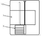
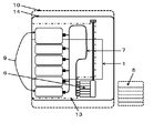
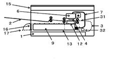
- FIG. 1 is a paper cassette
- 2 is a paper discharge tray
- printed paper is conveyed from 1 to 2 through a paper path indicated by a dotted line 3 and discharged.
- ink droplets are ejected from the print head 4 according to information, and printing is performed.
- Reference numeral 5 denotes a replaceable on-carriage ink tank.
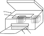
- FIG. 3 is a perspective view showing how the on-carriage ink tank in this conventional machine is replaced. Open the upper mechanism of the tank, and at the same time move the carriage to the center and then replace it.
- the typical size of the ink tank is approximately 1.5 cm in width, 5 to 7 cm in depth, and 4 to 5 cm in height, and this is mounted on the carriage in a replaceable manner.
- a black ink whose main purpose is to print characters is usually about twice as wide as the above.
- the number of tanks may be a combination of black and four yellow, magenta, and cyan, or six plus photo magenta and photocyan, and seven convenient plus black for photography. Furthermore, there is a configuration in which the number of colors is increased in order to further improve the picture quality. In these cases, the total width of all color tanks is around 7-10 cm.
- the carriage has a firm mechanism for ensuring the ease of replacement of the ink cartridge by the user, and the thickness is also a value added thereto.
- the on-carriage ink tank method has not increased the ink capacity for many years.
- the total width is about 7 cm.
- a width in the width direction of 14 cm is required. Even in such a relatively narrow product group of ink cartridges, the increase in the amount of ink remains unchanged.
- the content of the ink tank in the above example is over 30cc.
- the on-carriage ink tank is essentially located above the print head, and basically the head pressure is applied to the print head, and unless it is a very shallow ink tank, ink will leak out of the print head if no action is taken . Therefore, sponge-like stuffing, a maze, or a valve is provided to prevent ink from dropping from the print head.
- cited document 1 Japanese Patent Application Laid-Open No. 07-068773. Although this technique is later improved and is considered to be used in actual products, the use efficiency of the ink cartridge volume drops to almost half due to this filling, and the effective ink amount is about 15 cc, for example.
- the ink consumption is about half that of the standard manuscript printing, and the ink consumption per sheet is approximately 0. It is 05 cc (the converted value from the sum of the ink amount actually used for printing and the ink amount used for maintenance). Therefore, it can be said that printing of approximately 300 sheets / one ink cartridge is possible in calculation. This is consistent with the upper limit of the actual feeling of many users. (In this proposal, the description will be continued using 0.05 cc of ink consumption per sheet)
- JP-A-2001-138541, JP-A-2010-228237, JP-A-2009-226026 and JP-A-2009-226026 can be referred to.
- a buffer chamber (called a sub-tank) is decompressed to a negative pressure state by a pump to stabilize printing, and if necessary, the buffer chamber is pressurized to a positive pressure state to store the stored ink.
- the printer head automatically sends it out. In any case, it is possible to suck up automatically using a negative pressure derived from the print head up to a depth of about 3 cm, and a suction pump is required at a depth exceeding this.
- a sensor, a switching valve, a control device, and the like are inevitably required, resulting in a costly configuration. *
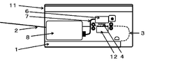
- a recording apparatus that avoids a paper feed mechanism and a print head recovery mechanism (indicated by reference numeral 12 below the on-carriage ink tank 6 in the figure) as schematically shown in FIGS. 11 can be seen in which a replacement off-carriage ink tank is provided at a location on one side of the 11. This is the place indicated by the number 8.
- Reference numeral 7 denotes a flexible ink conduit connecting the two ink tanks.
- the replacement off-carriage ink tank can be somewhat longer in the rear side direction of the recording apparatus main body, and the amount of stored ink can be increased.
- the width of the ink tank affects the width of the main body and cannot be so large.
- One of the answers to increase the ink storage capacity without using a force such as a pump is to place a replacement ink tank above the print head and control the head pressure on the print head caused by the ink in this tank.
- a pressure control mechanism is provided in the on-carriage ink tank, and the height of the replacement ink tank is set so as to correspond to the negative pressure fluctuation allowable range of the liquid chamber connected to the print head.
- This ink supply system has an “expansion degree of freedom” that can be arranged to fill the entire width of the printing apparatus main body although the height width of the off-carriage ink tank is restricted.
- a long space can be obtained in the rear side direction of the recording apparatus main body.
- it is as simple as a small valve, it requires a hydraulic head pressure control mechanism.
- the present invention relates to the disposition of the replacement off-carriage ink tank below the print head, and (1) it is easy to increase the capacity of the stored ink and expand the stored ink amount and the number of colors. It has a degree of freedom, (2) is user-friendly in ink tank replacement, (3) does not widen the main body, and (4) aims to realize a simple and inexpensive configuration that makes it a consumer product. Is.
- the main premise is that the ink does not fall off from the print head and has stable ink supply performance that does not hinder ink ejection.
- an ink jet recording apparatus at least an on-carriage ink tank integrated with a print head, a replaceable refill ink tank, and the refill
- the ink supply system is composed of a flexible ink conduit that guides ink from the ink tank to the on-carriage ink tank, the replenishment ink tank is arranged below the print head, and its central position is Hmm below the print head.
- the replacement ink tank is placed under the condition that h ⁇ p and
- it is P, in the lateral direction and the depth direction of the recording apparatus main body, it is an arbitrary position in the space over the entire area avoiding the print head recovery mechanism and the paper feeding mechanism. is there.
- the problem solving means 4 is the problem solving means 1, 2, and 3, in which the paper discharge tray positioned immediately above the space for arranging the replaceable refilling ink tank is automatically placed in the recording apparatus main body when the recording apparatus is stopped or stopped.
- the ink jet recording apparatus is automatically retracted and stored, and automatically extends or retracts from the storage position in the main body during operation of the recording apparatus.
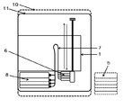
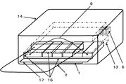
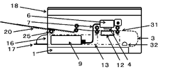
- FIGS. 6 and 7 The arrangement of the main components of the recording apparatus 14 of the present invention is schematically shown in FIGS. 6 (transverse sectional view) and 7 (plan view).
- a space indicated by an alternate long and short dash line 13 is a space that can store the lower off-carriage ink tank (replacement ink tank) 9 defined in the present invention. Details will be described later.
- the center position of the replacement ink tank in the height direction is set to be Hmm below the print head.
- the width in the height direction is ⁇ hmm from the center position, that is, 2 hmm.
- (H ⁇ h) mm is the ink height when the ink is full, and (H + h) mm is the height immediately before the ink reaches the bottom.
- a negative pressure range that does not leak ink from the print head (so-called no dropping of the ink) and is not so high as to cause ejection becomes ⁇ (P ⁇ p) mmH 2 O.
- hp ⁇ PH ⁇ ph (3) Is guided.
- ⁇ p (4) Is guided. That is, the height width 2h of the replacement ink tank is 2p or less of the allowable fluctuation range of the negative pressure, and the difference between the center value H of the tank position and the central value P of the allowable negative pressure is 1/2 of the allowable fluctuation range. p or less.
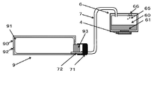
- the replacement ink tank 9 includes a connecting seal member 93.
- the connecting mechanism 71 of the printer body is provided with a needle 72.
- the ink communicates from the needle 72 to the ink chamber 60 of the on-carriage ink tank 6 through the flexible ink conduit 7.
- various related elements such as a means to prevent unnecessary air from entering, a mechanism for notifying that ink has been emptied before that, and an ink tank replacement sequence (preliminary ejection, head cleaning, etc.). These may be appropriately incorporated from many excellent known techniques. The description will be continued focusing on the skeleton of the present invention.
- a buffer mechanism for protecting the print head and mitigating the turbulent movement of the ink as shown by reference numeral 61 is provided.
- This uses a continuous porous material, such as a sponge or fiber stuffing. Alternatively, a maze-like buffer mechanism described later is also effective.
- the problem of mixed bubbles is inherent. That is, if bubbles are mixed in the ink chamber 60 for some reason (melted gas, mixed gas at the time of ink tank replacement, etc.), it expands when the liquid temperature rises, etc., causing the ink head to drop unintentionally from the print head 4. . Bubbles are exemplarily shown in FIG. 9 and FIG. In order to prevent such an inconvenience, a mechanism 66 that performs “gas release or excessive positive pressure release” is necessary. In an inkjet printer, this mechanism is basically incorporated in all on-carriage ink tanks.
- negative pressure accompanying the delivery should not be generated here.
- a device such as using a hard ink container 90 and using an ink bag 91 that is soft and deflated naturally as the ink is delivered is required. It is important to provide a hole 92 for taking in air in the hard ink container 90 in order to prevent the generation of negative pressure. Many other mechanisms with similar performance have been proposed.
- the place where the replacement ink tank 9 can be stored is a space above the paper cassette 1 and below the paper transport path 31 directly below the print head, as indicated by a dashed line 13 in FIG.
- the height width of the replacement ink tank 9 housed here is equivalent to 2 pmm at the maximum as described above, and is not necessarily a large value. Although it depends on the negative pressure fluctuation allowable width 2p determined by the ink properties and the print head shape, it is at most about 40 mm.
- the paper conveyance path 31 directly under the print head needs to be configured higher than that of the conventional recording apparatus.
- the on-carriage ink tank is small because it is not intended to store ink here. Height, width, and depth if necessary. Therefore, even if the paper conveyance path 31 directly under the print head is higher than that of the conventional recording apparatus, the height of the recording apparatus is almost the same as that of the conventional apparatus.
- the place where the replacement ink tank 9 can be accommodated is the one-dot chain line 13, but another limitation is to avoid the print head recovery mechanism (lower part of the on-carriage ink tank in FIG. 6, indicated by reference numeral 12). .
- the drive transmission mechanism should be arranged on the exterior portion side as much as possible and that the feed roller for paper conveyance should be as small as possible.
- the restriction in the depth direction is the paper pickup roller No. 32 in FIG.
- the stowable space 13 can be extended up to this position. In this way, the place where the replacement ink tank 9 can be stored, the one-dot chain line space 13 is not high in height, but can be created as a huge space having a full width and a long depth of the recording apparatus. It is.
- An object of the present invention is also not to increase the size of the recording apparatus.
- the height of the on-carriage ink tank that has been used without change for 20 years is a trade-off that you want to install as much ink as possible, but you must avoid ink dropping.
- the height continues to be approximately 40 mm to 50 mm.
- the on-carriage ink tank integrated with the print head is not intended to store ink here, so it can be smaller.
- a height of about 10 mm to 15 mm is sufficient. Compared with the conventional machine, it is 30 mm to 40 mm lower, and accordingly, the paper conveyance path 31 directly below the print head can be lifted upward to widen the lower space.
- the storage space 13 has a height of 30 mm, and a replacement ink tank having a height of, for example, 20 mm can be mounted therein.
- a replacement ink tank having a height of, for example, 20 mm can be mounted therein.
- the ink capacity is 64 cc.
- the width of the recording device can be reduced. Although it is repeated, it was described in the previous section that “the on-carriage ink tank is small because it is not intended to store ink here”, but this is not only the height.
- the width can be reduced. For example, within a few mm, and within 1 cm anyway. This number is merely an example, but it should be understood that the greater the number of ink colors, the greater the effect because the effect on the recording apparatus main body width is doubled.
- the ink tank 5 of the conventional machine is indicated by a dotted line on the right side of FIG.
- the size of this conventional machine is a dotted line 10 in FIG.
- the black for characters is made large, for example, 60 mm wide.
- the ink tank width for other colors is 40 mm.
- a product that is at least 5 cm narrower than a conventional machine with the same six colors can be made.
- the printable number of color ink tanks is shown above.
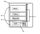
- the replacement ink tank is disposed at the lower position on the front side facing the user of the main body, and can be arranged side by side in a horizontal line there. It is very easy for the user to exchange.
- the upper lid is opened, and in the case of a multifunction machine, the upper scanner is lifted together, but the ink tank is exchanged so as to look into it.
- the ink tank housing door 17 on the front surface is opened, and the necessary ink tank 9 is replaced from the ink tank housing outlet 16. The ease of handling of both is obvious.
- the paper discharge tray 2 is directly above the storage portion outlet 16 and the door 17 for replacement of the replenishment ink tank, so that it is difficult to replace the ink tank.
- this discharge tray is automatically retracted and stored in the main body of the recording apparatus during the pause or stop, and is automatically extended when used. added.
- the user can replace the ink tank without being disturbed by the paper discharge tray.
- it does not deny such a mechanism that performs manual removal and flip-up, or manual storage and withdrawal as in the conventional machine.
- the depth and width of the ink tank may be slightly narrowed to increase the depth. In this way, the degree of freedom in design becomes extremely high. However, it is essential that the inner height 2h of the ink tank is 2pmm, and it is only necessary to keep this.
- FIG. Schematic diagram of ink tank replacement Cross-sectional view of off-carriage ink tank lateral arrangement recording device
- FIG. Schematic diagram of ink tank arrangement example and replacement Relationship diagram between ink tank for replacement at lower position and on-carriage ink tank, Part 1 2 Maze type ink disturbance buffer mechanism
- Cross-sectional view of the large replacement ink tank lower recording device The plan view Cross section of automatic extension type paper tray mounted recording device
- the basic configuration of the recording apparatus of FIGS. 6, 7, and 8 used in the above description and the arrangement suitable for the self-pumping conditions shown in the relational diagrams of FIGS. 9 and 10 are typical forms of the present invention.
- a specific configuration is shown by a consumer product genre photo printer using six colors of black, yellow, magenta, cyan, photo magenta, and photocyan.
- the depth of this ink tank was 5.0 cm in internal dimensions. This is not particularly short. This is because there is a sufficient margin in the depth direction of this place.
- the height was 1.4 cm for the outer dimension and 1.0 cm for the inner dimension.
- the capacity is 4.5 cc.
- the free ink liquid amount (liquid amount excluding the liquid amount contained in the buffer member) is about 3 cc. This is the amount of liquid capable of printing about 100 sheets by continuous printing.
- 0.03 cc is used for printing one standard original. This means that the on-carriage ink tank is always replenished with ink, and even if there is a slight replenishment time lag, and even in the case of continuous printing, this is an amount that can be printed.
- the replacement of the ink tank by the user is inevitably performed by opening the ink tank storage section door 17 on the lower side of the paper discharge tray 2 and from the ink tank storage section outlet 16.
- the ink tank replacement is performed by removing the paper discharge tray 2 above the ink tank storage section takeout port 16 or pushing it into the recording apparatus main body each time. Have to do.
- the paper discharge tray should be automatically pulled into the recording device body when the ink tank is replaced.
- the unused paper discharge tray protrudes and does not get in the way, and the appearance is also clear.
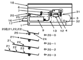
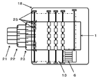
- Reference numeral 20 denotes an automatic extension type paper discharge tray.
- the automatic extension type paper discharge tray 20 is composed of three extension type paper discharge trays 21, 22 and 23 made of steel round bars. At both left and right ends, a round bar was squeezed long in the vertical direction, and a linear gear 24 was cut in the lower part.
- a paper discharge tray drive gear 25 is placed in correspondence with the linear gear 24 at the forefront portion inside the recording apparatus main body. Explanatory diagrams of the movement of the extension type paper discharge tray are shown at 20-0, 20-1, 20-2 and 20-3 at the bottom of FIG.
- the starting point is 20-0, and the first-stage extension type paper discharge tray 21 on which 22 and 23 are placed is sent out by the rotation of the drive gear 25.
- This is 20-1 in FIG.
- the drive gear 25 is engaged with the extension 22 of the extension type paper discharge tray 23 as a second stage and sends it out.
- This is 20-2 in FIG.
- the third stage it is combined with the extension type paper discharge tray 23 and sent out. This is 20-3 in FIG.
- FIG. 15 is a plan view corresponding to 20-0 in FIG. 14, which is a starting point where the automatic extension type paper discharge tray 20 is accommodated.
- the recording apparatus is paused or shut down, and the paper discharge tray is not ejected from the recording apparatus.
- the user can replace the ink tank without being disturbed by the paper discharge tray.
- FIG. 16 shows a state where the first-stage extension type paper discharge tray 21 is sent out when the recording apparatus is restarted. It is a top view of the state of 20-1 of FIG.
- FIG. 17 is a plan view corresponding to 20-2 of FIG. 14, where the second-stage extension type paper discharge tray 22 on which the tray 21 is placed is sent out.
- FIG. 18 is a plan view corresponding to 20-3 in FIG. 14, where the third-stage extension type paper discharge tray 23 on which the trays 21 and 22 are placed is sent out.
- FIG. 19 is a cross-sectional view showing a state in which all three stages of the extension type paper discharge tray are extended.
- an apparatus for controlling these series of movements is necessary. It is one of the general design items and is not special. It is also possible to detect the presence or absence of printed matter on the paper discharge tray, and automatically reverse the drive gear 25 if there is not, and store the extension type paper discharge tray in the recording apparatus main body in the reverse order. is there. Naturally, regardless of whether it is by the user or automatic, the drive gear 25 is reversed before the shutdown is entered, and the tray is stored in the main body.
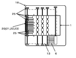
- a replacement ink tank capable of printing 10,000 sheets can be easily designed.
- the black ink tank has a lateral width of 12 cm and a depth of 22 cm
- the ink tank capacity is 2 cm ⁇ 12 cm ⁇ 22 cm and is 528 cc, that is, the printable number is 10,560.
- the depth length was 18 cm and the width was 9 cm, avoiding the printhead recovery mechanism.
- FIG. 12 and FIG. 13 show the recording apparatus 15 equipped with this large replacement ink tank.
- the replacement ink tank group 9 and its accommodating space 13 are displayed in the center, and other carriage parts, ink conduits, and paper feeding mechanisms are omitted.
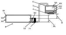
- FIG. 11 shows another embodiment of the ink disturbance buffer mechanism.
- An ink disturbance relaxation mechanism including a maze 62 is provided.
- Other numbers are the same as those in FIGS. 9 and 10.
- the extending / drawing and retracting / storing mechanisms of the recording devices 18 and 19 having the automatic extension type paper discharge tray according to the embodiment of the present invention are widely used in other fields and are not special. Incorporation of other similar automatic mechanisms into recording devices should be used as appropriate. Although it is not certain whether or not such an automatic extension / storage type paper discharge tray exists in the ink jet type recording apparatus so far, the “configuration with the paper discharge tray immediately above the ink tank outlet” of the present invention "Is a design consideration that is very user-friendly but not necessary.
- the present invention is not limited to the above embodiment, and various elemental technologies proposed for known ink jet recording apparatuses can be used according to the purpose of design to determine the height position of the replacement ink tank.
- the present invention has been mainly described for an inkjet recording apparatus as a consumer product, and its application to a business use printer has also been introduced. It can also be applied to large format printers, professional photographic printers, or industrial printers that may be costly. And even portable printers can have a significant effect if you use them, depending on your design goals.
Landscapes
- Ink Jet (AREA)
Applications Claiming Priority (2)
| Application Number | Priority Date | Filing Date | Title |
|---|---|---|---|
| JP2012-104996 | 2012-05-01 | ||
| JP2012104996A JP2013230651A (ja) | 2012-05-01 | 2012-05-01 | インクジェット記録装置 |
Publications (1)
| Publication Number | Publication Date |
|---|---|
| WO2013165012A1 true WO2013165012A1 (ja) | 2013-11-07 |
Family
ID=49514410
Family Applications (1)
| Application Number | Title | Priority Date | Filing Date |
|---|---|---|---|
| PCT/JP2013/062694 Ceased WO2013165012A1 (ja) | 2012-05-01 | 2013-05-01 | インクジェット記録装置 |
Country Status (2)
| Country | Link |
|---|---|
| JP (1) | JP2013230651A (enExample) |
| WO (1) | WO2013165012A1 (enExample) |
Cited By (1)
| Publication number | Priority date | Publication date | Assignee | Title |
|---|---|---|---|---|
| WO2019147238A1 (en) * | 2018-01-25 | 2019-08-01 | Hewlett-Packard Development Company, L.P. | Tanks for print cartridge |
Families Citing this family (4)
| Publication number | Priority date | Publication date | Assignee | Title |
|---|---|---|---|---|
| US10632762B2 (en) | 2017-02-02 | 2020-04-28 | Ricoh Company, Ltd. | Heating apparatus and image forming system |
| JP7091753B2 (ja) * | 2017-10-20 | 2022-06-28 | セイコーエプソン株式会社 | 液体噴射装置 |
| JP7669760B2 (ja) * | 2021-03-30 | 2025-04-30 | ブラザー工業株式会社 | 液体吐出装置 |
| JP7661810B2 (ja) * | 2021-07-02 | 2025-04-15 | セイコーエプソン株式会社 | 記録装置 |
Citations (4)
| Publication number | Priority date | Publication date | Assignee | Title |
|---|---|---|---|---|
| JP2002144601A (ja) * | 2000-11-16 | 2002-05-22 | Canon Inc | サブインクタンク及びインクジェット記録装置 |
| JP2003112435A (ja) * | 2001-08-01 | 2003-04-15 | Canon Inc | 液体供給装置および液体吐出記録装置 |
| JP2006110900A (ja) * | 2004-10-15 | 2006-04-27 | Canon Inc | インクジェット記録装置 |
| JP2006327802A (ja) * | 2005-05-30 | 2006-12-07 | Canon Inc | インクジェット記録装置 |
Family Cites Families (7)
| Publication number | Priority date | Publication date | Assignee | Title |
|---|---|---|---|---|
| JP3818194B2 (ja) * | 2002-03-28 | 2006-09-06 | ブラザー工業株式会社 | 記録装置 |
| JP2003334967A (ja) * | 2002-05-22 | 2003-11-25 | Canon Inc | 液体供給装置 |
| JP3750808B2 (ja) * | 2002-07-26 | 2006-03-01 | ブラザー工業株式会社 | インクジェットプリンタ |
| JP2004174815A (ja) * | 2002-11-26 | 2004-06-24 | Canon Inc | インクヘッド一定負圧発生装置 |
| JP4782602B2 (ja) * | 2006-03-31 | 2011-09-28 | 富士フイルム株式会社 | インクジェット記録装置及びインクジェット記録方法 |
| JP4806616B2 (ja) * | 2006-09-29 | 2011-11-02 | 富士フイルム株式会社 | インクカートリッジ及びインクジェット記録装置 |
| JP5471599B2 (ja) * | 2010-03-02 | 2014-04-16 | 株式会社リコー | 画像形成装置 |
-
2012
- 2012-05-01 JP JP2012104996A patent/JP2013230651A/ja active Pending
-
2013
- 2013-05-01 WO PCT/JP2013/062694 patent/WO2013165012A1/ja not_active Ceased
Patent Citations (4)
| Publication number | Priority date | Publication date | Assignee | Title |
|---|---|---|---|---|
| JP2002144601A (ja) * | 2000-11-16 | 2002-05-22 | Canon Inc | サブインクタンク及びインクジェット記録装置 |
| JP2003112435A (ja) * | 2001-08-01 | 2003-04-15 | Canon Inc | 液体供給装置および液体吐出記録装置 |
| JP2006110900A (ja) * | 2004-10-15 | 2006-04-27 | Canon Inc | インクジェット記録装置 |
| JP2006327802A (ja) * | 2005-05-30 | 2006-12-07 | Canon Inc | インクジェット記録装置 |
Cited By (3)
| Publication number | Priority date | Publication date | Assignee | Title |
|---|---|---|---|---|
| WO2019147238A1 (en) * | 2018-01-25 | 2019-08-01 | Hewlett-Packard Development Company, L.P. | Tanks for print cartridge |
| CN111565934A (zh) * | 2018-01-25 | 2020-08-21 | 惠普发展公司,有限责任合伙企业 | 用于打印盒的罐 |
| US11298944B2 (en) | 2018-01-25 | 2022-04-12 | Hewlett-Packard Development Company, L.P. | Tanks for print cartridge |
Also Published As
| Publication number | Publication date |
|---|---|
| JP2013230651A (ja) | 2013-11-14 |
Similar Documents
| Publication | Publication Date | Title |
|---|---|---|
| CN100404264C (zh) | 一种墨盒以及具有该墨盒的供墨系统 | |
| JP6498098B2 (ja) | 記録装置および液体収容部材 | |
| JP7327976B2 (ja) | インクジェット記録装置およびインクタンク | |
| JP7604565B2 (ja) | インクジェット記録装置およびインクタンク | |
| WO2013165012A1 (ja) | インクジェット記録装置 | |
| JP2013184424A (ja) | インクジェット記録装置 | |
| CN114055948B (zh) | 打印设备和液体储存容器 | |
| JP2014151512A (ja) | 液体容器、液体供給システム | |
| JP5994043B2 (ja) | インクジェット記録装置 | |
| JP2019043019A (ja) | インクタンクおよびインクジェット記録装置 | |
| JP2014180797A (ja) | 画像記録装置 | |
| JP2019116017A (ja) | 液体排出装置 | |
| JP6969196B2 (ja) | 液体消費装置 | |
| JP4608730B2 (ja) | インクジェットプリンタ及びそのヘッドカートリッジ | |
| JP6508569B2 (ja) | インクジェットプリンタ | |
| US10457064B2 (en) | Liquid consumption apparatus having cartridge, cartridge attachment section provided with tank, and consuming device | |
| JP7035647B2 (ja) | システム | |
| JP4557410B2 (ja) | サブインクタンク、インクジェットヘッドカートリッジ、及びインクジェット記録装置 | |
| JP2022026847A (ja) | インクジェット記録装置及びインクタンク | |
| JP7248165B2 (ja) | システム | |
| JP2000141695A (ja) | 液体吐出記録装置 | |
| JP6666052B2 (ja) | 記録装置 | |
| JP5842604B2 (ja) | インク供給装置及び画像記録装置 | |
| JP2000218815A (ja) | インクジェット記録装置 | |
| JP6296377B2 (ja) | 液体カートリッジ |
Legal Events
| Date | Code | Title | Description |
|---|---|---|---|
| 121 | Ep: the epo has been informed by wipo that ep was designated in this application |
Ref document number: 13784437 Country of ref document: EP Kind code of ref document: A1 |
|
| DPE2 | Request for preliminary examination filed before expiration of 19th month from priority date (pct application filed from 20040101) | ||
| NENP | Non-entry into the national phase |
Ref country code: DE |
|
| 122 | Ep: pct application non-entry in european phase |
Ref document number: 13784437 Country of ref document: EP Kind code of ref document: A1 |