WO2013165012A1 - Inkjet recording device - Google Patents
Inkjet recording device Download PDFInfo
- Publication number
- WO2013165012A1 WO2013165012A1 PCT/JP2013/062694 JP2013062694W WO2013165012A1 WO 2013165012 A1 WO2013165012 A1 WO 2013165012A1 JP 2013062694 W JP2013062694 W JP 2013062694W WO 2013165012 A1 WO2013165012 A1 WO 2013165012A1
- Authority
- WO
- WIPO (PCT)
- Prior art keywords
- ink
- ink tank
- print head
- recording apparatus
- carriage
- Prior art date
Links
Images


Classifications
-
- B—PERFORMING OPERATIONS; TRANSPORTING
- B41—PRINTING; LINING MACHINES; TYPEWRITERS; STAMPS
- B41J—TYPEWRITERS; SELECTIVE PRINTING MECHANISMS, i.e. MECHANISMS PRINTING OTHERWISE THAN FROM A FORME; CORRECTION OF TYPOGRAPHICAL ERRORS
- B41J2/00—Typewriters or selective printing mechanisms characterised by the printing or marking process for which they are designed
- B41J2/005—Typewriters or selective printing mechanisms characterised by the printing or marking process for which they are designed characterised by bringing liquid or particles selectively into contact with a printing material
- B41J2/01—Ink jet
- B41J2/17—Ink jet characterised by ink handling
- B41J2/175—Ink supply systems ; Circuit parts therefor
- B41J2/17503—Ink cartridges
- B41J2/17513—Inner structure
-
- B—PERFORMING OPERATIONS; TRANSPORTING
- B41—PRINTING; LINING MACHINES; TYPEWRITERS; STAMPS
- B41J—TYPEWRITERS; SELECTIVE PRINTING MECHANISMS, i.e. MECHANISMS PRINTING OTHERWISE THAN FROM A FORME; CORRECTION OF TYPOGRAPHICAL ERRORS
- B41J29/00—Details of, or accessories for, typewriters or selective printing mechanisms not otherwise provided for
- B41J29/02—Framework
-
- B—PERFORMING OPERATIONS; TRANSPORTING
- B41—PRINTING; LINING MACHINES; TYPEWRITERS; STAMPS
- B41J—TYPEWRITERS; SELECTIVE PRINTING MECHANISMS, i.e. MECHANISMS PRINTING OTHERWISE THAN FROM A FORME; CORRECTION OF TYPOGRAPHICAL ERRORS
- B41J29/00—Details of, or accessories for, typewriters or selective printing mechanisms not otherwise provided for
- B41J29/12—Guards, shields or dust excluders
- B41J29/13—Cases or covers
Definitions
- Inkjet recording devices used in homes and offices elucidating basic element conditions of simple ink supply that uses only negative pressure derived from the print head and does not use auxiliary devices, and based on that, without increasing the size of the main body of the device
- the present invention relates to an ink jet recording apparatus having a configuration that significantly increases the capacity of mounted ink that is a consumable.
- a widely used inkjet recording apparatus has a carriage on which a print head that reciprocates in a direction perpendicular to the paper traveling direction is mounted, and ink tanks of various colors are mounted on the carriage in a replaceable manner.
- another ink tank group is provided separately from the ink tank on the carriage, and the method of supplying ink from there to the ink tank on the carriage is also adopted depending on the purpose of use of the recording device. ing. In either method, stable ink supply to the print head is a basic problem, and various ideas have been accumulated for better solutions.
- Inkjet recording devices of the consumer product genre are on-carriage ink tanks, which are consumables that can be replaced when ink runs out. These are called ink cartridges, but this method is the mainstream and is used in most products. ing.
- the ink cartridge, which is a consumable item, has not changed the amount of ink that can actually be printed and the price, despite the enormous production volume for a long time.
- the ink cartridges that are often used in the Japanese market are composed of four color inks of black, yellow, magenta, and cyan. Replacing the cost will cost nearly 5,000 yen.
- the number of sheets that can be printed in A4 size in the standard manuscript / standard printing mode (ISO / IEC2472 and 2471 compliant) is about 500. Therefore, the cost of printing ink for one sheet is about 10 yen.
- the catalog generally contains numbers of such a level. Since four colors of ink are used, the average number is 125 printable sheets per one color ink cartridge. Too little for the price.
- printers with a price of, for example, 4,800 yen or 5,800 yen appear at the store and are often bought.
- the dissatisfaction that “ink price is high” is also a problem in sales, so we will consider it, and we would like to respond to the dissatisfaction that “ink will soon disappear”. Since the solution should be a large-capacity ink cartridge, it is of course necessary that the ink cost per sheet can be reduced.
- each color ink tank is mounted on the carriage in a replaceable manner.
- an on-carriage ink tank system In addition to the ink tank fixed on the carriage, another type of replaceable ink tank for replenishing ink and supplying the ink from there to the ink tank on the carriage is called an off-carriage ink tank method. I will decide. .
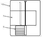
- FIG. 1 is a paper cassette
- 2 is a paper discharge tray
- printed paper is conveyed from 1 to 2 through a paper path indicated by a dotted line 3 and discharged.
- ink droplets are ejected from the print head 4 according to information, and printing is performed.
- Reference numeral 5 denotes a replaceable on-carriage ink tank.
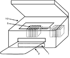
- FIG. 3 is a perspective view showing how the on-carriage ink tank in this conventional machine is replaced. Open the upper mechanism of the tank, and at the same time move the carriage to the center and then replace it.
- the typical size of the ink tank is approximately 1.5 cm in width, 5 to 7 cm in depth, and 4 to 5 cm in height, and this is mounted on the carriage in a replaceable manner.
- a black ink whose main purpose is to print characters is usually about twice as wide as the above.
- the number of tanks may be a combination of black and four yellow, magenta, and cyan, or six plus photo magenta and photocyan, and seven convenient plus black for photography. Furthermore, there is a configuration in which the number of colors is increased in order to further improve the picture quality. In these cases, the total width of all color tanks is around 7-10 cm.
- the carriage has a firm mechanism for ensuring the ease of replacement of the ink cartridge by the user, and the thickness is also a value added thereto.
- the on-carriage ink tank method has not increased the ink capacity for many years.
- the total width is about 7 cm.
- a width in the width direction of 14 cm is required. Even in such a relatively narrow product group of ink cartridges, the increase in the amount of ink remains unchanged.
- the content of the ink tank in the above example is over 30cc.
- the on-carriage ink tank is essentially located above the print head, and basically the head pressure is applied to the print head, and unless it is a very shallow ink tank, ink will leak out of the print head if no action is taken . Therefore, sponge-like stuffing, a maze, or a valve is provided to prevent ink from dropping from the print head.
- cited document 1 Japanese Patent Application Laid-Open No. 07-068773. Although this technique is later improved and is considered to be used in actual products, the use efficiency of the ink cartridge volume drops to almost half due to this filling, and the effective ink amount is about 15 cc, for example.
- the ink consumption is about half that of the standard manuscript printing, and the ink consumption per sheet is approximately 0. It is 05 cc (the converted value from the sum of the ink amount actually used for printing and the ink amount used for maintenance). Therefore, it can be said that printing of approximately 300 sheets / one ink cartridge is possible in calculation. This is consistent with the upper limit of the actual feeling of many users. (In this proposal, the description will be continued using 0.05 cc of ink consumption per sheet)
- JP-A-2001-138541, JP-A-2010-228237, JP-A-2009-226026 and JP-A-2009-226026 can be referred to.
- a buffer chamber (called a sub-tank) is decompressed to a negative pressure state by a pump to stabilize printing, and if necessary, the buffer chamber is pressurized to a positive pressure state to store the stored ink.
- the printer head automatically sends it out. In any case, it is possible to suck up automatically using a negative pressure derived from the print head up to a depth of about 3 cm, and a suction pump is required at a depth exceeding this.
- a sensor, a switching valve, a control device, and the like are inevitably required, resulting in a costly configuration. *
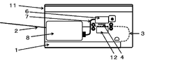
- a recording apparatus that avoids a paper feed mechanism and a print head recovery mechanism (indicated by reference numeral 12 below the on-carriage ink tank 6 in the figure) as schematically shown in FIGS. 11 can be seen in which a replacement off-carriage ink tank is provided at a location on one side of the 11. This is the place indicated by the number 8.
- Reference numeral 7 denotes a flexible ink conduit connecting the two ink tanks.
- the replacement off-carriage ink tank can be somewhat longer in the rear side direction of the recording apparatus main body, and the amount of stored ink can be increased.
- the width of the ink tank affects the width of the main body and cannot be so large.
- One of the answers to increase the ink storage capacity without using a force such as a pump is to place a replacement ink tank above the print head and control the head pressure on the print head caused by the ink in this tank.
- a pressure control mechanism is provided in the on-carriage ink tank, and the height of the replacement ink tank is set so as to correspond to the negative pressure fluctuation allowable range of the liquid chamber connected to the print head.
- This ink supply system has an “expansion degree of freedom” that can be arranged to fill the entire width of the printing apparatus main body although the height width of the off-carriage ink tank is restricted.
- a long space can be obtained in the rear side direction of the recording apparatus main body.
- it is as simple as a small valve, it requires a hydraulic head pressure control mechanism.
- the present invention relates to the disposition of the replacement off-carriage ink tank below the print head, and (1) it is easy to increase the capacity of the stored ink and expand the stored ink amount and the number of colors. It has a degree of freedom, (2) is user-friendly in ink tank replacement, (3) does not widen the main body, and (4) aims to realize a simple and inexpensive configuration that makes it a consumer product. Is.
- the main premise is that the ink does not fall off from the print head and has stable ink supply performance that does not hinder ink ejection.
- an ink jet recording apparatus at least an on-carriage ink tank integrated with a print head, a replaceable refill ink tank, and the refill
- the ink supply system is composed of a flexible ink conduit that guides ink from the ink tank to the on-carriage ink tank, the replenishment ink tank is arranged below the print head, and its central position is Hmm below the print head.
- the replacement ink tank is placed under the condition that h ⁇ p and
- it is P, in the lateral direction and the depth direction of the recording apparatus main body, it is an arbitrary position in the space over the entire area avoiding the print head recovery mechanism and the paper feeding mechanism. is there.
- the problem solving means 4 is the problem solving means 1, 2, and 3, in which the paper discharge tray positioned immediately above the space for arranging the replaceable refilling ink tank is automatically placed in the recording apparatus main body when the recording apparatus is stopped or stopped.
- the ink jet recording apparatus is automatically retracted and stored, and automatically extends or retracts from the storage position in the main body during operation of the recording apparatus.
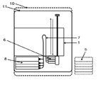
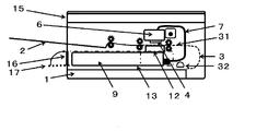
- FIGS. 6 and 7 The arrangement of the main components of the recording apparatus 14 of the present invention is schematically shown in FIGS. 6 (transverse sectional view) and 7 (plan view).
- a space indicated by an alternate long and short dash line 13 is a space that can store the lower off-carriage ink tank (replacement ink tank) 9 defined in the present invention. Details will be described later.
- the center position of the replacement ink tank in the height direction is set to be Hmm below the print head.
- the width in the height direction is ⁇ hmm from the center position, that is, 2 hmm.
- (H ⁇ h) mm is the ink height when the ink is full, and (H + h) mm is the height immediately before the ink reaches the bottom.
- a negative pressure range that does not leak ink from the print head (so-called no dropping of the ink) and is not so high as to cause ejection becomes ⁇ (P ⁇ p) mmH 2 O.
- hp ⁇ PH ⁇ ph (3) Is guided.
- ⁇ p (4) Is guided. That is, the height width 2h of the replacement ink tank is 2p or less of the allowable fluctuation range of the negative pressure, and the difference between the center value H of the tank position and the central value P of the allowable negative pressure is 1/2 of the allowable fluctuation range. p or less.
- the replacement ink tank 9 includes a connecting seal member 93.
- the connecting mechanism 71 of the printer body is provided with a needle 72.
- the ink communicates from the needle 72 to the ink chamber 60 of the on-carriage ink tank 6 through the flexible ink conduit 7.
- various related elements such as a means to prevent unnecessary air from entering, a mechanism for notifying that ink has been emptied before that, and an ink tank replacement sequence (preliminary ejection, head cleaning, etc.). These may be appropriately incorporated from many excellent known techniques. The description will be continued focusing on the skeleton of the present invention.
- a buffer mechanism for protecting the print head and mitigating the turbulent movement of the ink as shown by reference numeral 61 is provided.
- This uses a continuous porous material, such as a sponge or fiber stuffing. Alternatively, a maze-like buffer mechanism described later is also effective.
- the problem of mixed bubbles is inherent. That is, if bubbles are mixed in the ink chamber 60 for some reason (melted gas, mixed gas at the time of ink tank replacement, etc.), it expands when the liquid temperature rises, etc., causing the ink head to drop unintentionally from the print head 4. . Bubbles are exemplarily shown in FIG. 9 and FIG. In order to prevent such an inconvenience, a mechanism 66 that performs “gas release or excessive positive pressure release” is necessary. In an inkjet printer, this mechanism is basically incorporated in all on-carriage ink tanks.
- negative pressure accompanying the delivery should not be generated here.
- a device such as using a hard ink container 90 and using an ink bag 91 that is soft and deflated naturally as the ink is delivered is required. It is important to provide a hole 92 for taking in air in the hard ink container 90 in order to prevent the generation of negative pressure. Many other mechanisms with similar performance have been proposed.
- the place where the replacement ink tank 9 can be stored is a space above the paper cassette 1 and below the paper transport path 31 directly below the print head, as indicated by a dashed line 13 in FIG.
- the height width of the replacement ink tank 9 housed here is equivalent to 2 pmm at the maximum as described above, and is not necessarily a large value. Although it depends on the negative pressure fluctuation allowable width 2p determined by the ink properties and the print head shape, it is at most about 40 mm.
- the paper conveyance path 31 directly under the print head needs to be configured higher than that of the conventional recording apparatus.
- the on-carriage ink tank is small because it is not intended to store ink here. Height, width, and depth if necessary. Therefore, even if the paper conveyance path 31 directly under the print head is higher than that of the conventional recording apparatus, the height of the recording apparatus is almost the same as that of the conventional apparatus.
- the place where the replacement ink tank 9 can be accommodated is the one-dot chain line 13, but another limitation is to avoid the print head recovery mechanism (lower part of the on-carriage ink tank in FIG. 6, indicated by reference numeral 12). .
- the drive transmission mechanism should be arranged on the exterior portion side as much as possible and that the feed roller for paper conveyance should be as small as possible.
- the restriction in the depth direction is the paper pickup roller No. 32 in FIG.
- the stowable space 13 can be extended up to this position. In this way, the place where the replacement ink tank 9 can be stored, the one-dot chain line space 13 is not high in height, but can be created as a huge space having a full width and a long depth of the recording apparatus. It is.
- An object of the present invention is also not to increase the size of the recording apparatus.
- the height of the on-carriage ink tank that has been used without change for 20 years is a trade-off that you want to install as much ink as possible, but you must avoid ink dropping.
- the height continues to be approximately 40 mm to 50 mm.
- the on-carriage ink tank integrated with the print head is not intended to store ink here, so it can be smaller.
- a height of about 10 mm to 15 mm is sufficient. Compared with the conventional machine, it is 30 mm to 40 mm lower, and accordingly, the paper conveyance path 31 directly below the print head can be lifted upward to widen the lower space.
- the storage space 13 has a height of 30 mm, and a replacement ink tank having a height of, for example, 20 mm can be mounted therein.
- a replacement ink tank having a height of, for example, 20 mm can be mounted therein.
- the ink capacity is 64 cc.
- the width of the recording device can be reduced. Although it is repeated, it was described in the previous section that “the on-carriage ink tank is small because it is not intended to store ink here”, but this is not only the height.
- the width can be reduced. For example, within a few mm, and within 1 cm anyway. This number is merely an example, but it should be understood that the greater the number of ink colors, the greater the effect because the effect on the recording apparatus main body width is doubled.
- the ink tank 5 of the conventional machine is indicated by a dotted line on the right side of FIG.
- the size of this conventional machine is a dotted line 10 in FIG.
- the black for characters is made large, for example, 60 mm wide.
- the ink tank width for other colors is 40 mm.
- a product that is at least 5 cm narrower than a conventional machine with the same six colors can be made.
- the printable number of color ink tanks is shown above.
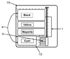
- the replacement ink tank is disposed at the lower position on the front side facing the user of the main body, and can be arranged side by side in a horizontal line there. It is very easy for the user to exchange.
- the upper lid is opened, and in the case of a multifunction machine, the upper scanner is lifted together, but the ink tank is exchanged so as to look into it.
- the ink tank housing door 17 on the front surface is opened, and the necessary ink tank 9 is replaced from the ink tank housing outlet 16. The ease of handling of both is obvious.
- the paper discharge tray 2 is directly above the storage portion outlet 16 and the door 17 for replacement of the replenishment ink tank, so that it is difficult to replace the ink tank.
- this discharge tray is automatically retracted and stored in the main body of the recording apparatus during the pause or stop, and is automatically extended when used. added.
- the user can replace the ink tank without being disturbed by the paper discharge tray.
- it does not deny such a mechanism that performs manual removal and flip-up, or manual storage and withdrawal as in the conventional machine.
- the depth and width of the ink tank may be slightly narrowed to increase the depth. In this way, the degree of freedom in design becomes extremely high. However, it is essential that the inner height 2h of the ink tank is 2pmm, and it is only necessary to keep this.
- FIG. Schematic diagram of ink tank replacement Cross-sectional view of off-carriage ink tank lateral arrangement recording device
- FIG. Schematic diagram of ink tank arrangement example and replacement Relationship diagram between ink tank for replacement at lower position and on-carriage ink tank, Part 1 2 Maze type ink disturbance buffer mechanism
- Cross-sectional view of the large replacement ink tank lower recording device The plan view Cross section of automatic extension type paper tray mounted recording device
- the basic configuration of the recording apparatus of FIGS. 6, 7, and 8 used in the above description and the arrangement suitable for the self-pumping conditions shown in the relational diagrams of FIGS. 9 and 10 are typical forms of the present invention.
- a specific configuration is shown by a consumer product genre photo printer using six colors of black, yellow, magenta, cyan, photo magenta, and photocyan.
- the depth of this ink tank was 5.0 cm in internal dimensions. This is not particularly short. This is because there is a sufficient margin in the depth direction of this place.
- the height was 1.4 cm for the outer dimension and 1.0 cm for the inner dimension.
- the capacity is 4.5 cc.
- the free ink liquid amount (liquid amount excluding the liquid amount contained in the buffer member) is about 3 cc. This is the amount of liquid capable of printing about 100 sheets by continuous printing.
- 0.03 cc is used for printing one standard original. This means that the on-carriage ink tank is always replenished with ink, and even if there is a slight replenishment time lag, and even in the case of continuous printing, this is an amount that can be printed.
- the replacement of the ink tank by the user is inevitably performed by opening the ink tank storage section door 17 on the lower side of the paper discharge tray 2 and from the ink tank storage section outlet 16.
- the ink tank replacement is performed by removing the paper discharge tray 2 above the ink tank storage section takeout port 16 or pushing it into the recording apparatus main body each time. Have to do.
- the paper discharge tray should be automatically pulled into the recording device body when the ink tank is replaced.
- the unused paper discharge tray protrudes and does not get in the way, and the appearance is also clear.
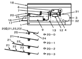
- Reference numeral 20 denotes an automatic extension type paper discharge tray.
- the automatic extension type paper discharge tray 20 is composed of three extension type paper discharge trays 21, 22 and 23 made of steel round bars. At both left and right ends, a round bar was squeezed long in the vertical direction, and a linear gear 24 was cut in the lower part.
- a paper discharge tray drive gear 25 is placed in correspondence with the linear gear 24 at the forefront portion inside the recording apparatus main body. Explanatory diagrams of the movement of the extension type paper discharge tray are shown at 20-0, 20-1, 20-2 and 20-3 at the bottom of FIG.
- the starting point is 20-0, and the first-stage extension type paper discharge tray 21 on which 22 and 23 are placed is sent out by the rotation of the drive gear 25.
- This is 20-1 in FIG.
- the drive gear 25 is engaged with the extension 22 of the extension type paper discharge tray 23 as a second stage and sends it out.
- This is 20-2 in FIG.
- the third stage it is combined with the extension type paper discharge tray 23 and sent out. This is 20-3 in FIG.
- FIG. 15 is a plan view corresponding to 20-0 in FIG. 14, which is a starting point where the automatic extension type paper discharge tray 20 is accommodated.
- the recording apparatus is paused or shut down, and the paper discharge tray is not ejected from the recording apparatus.
- the user can replace the ink tank without being disturbed by the paper discharge tray.
- FIG. 16 shows a state where the first-stage extension type paper discharge tray 21 is sent out when the recording apparatus is restarted. It is a top view of the state of 20-1 of FIG.
- FIG. 17 is a plan view corresponding to 20-2 of FIG. 14, where the second-stage extension type paper discharge tray 22 on which the tray 21 is placed is sent out.
- FIG. 18 is a plan view corresponding to 20-3 in FIG. 14, where the third-stage extension type paper discharge tray 23 on which the trays 21 and 22 are placed is sent out.
- FIG. 19 is a cross-sectional view showing a state in which all three stages of the extension type paper discharge tray are extended.
- an apparatus for controlling these series of movements is necessary. It is one of the general design items and is not special. It is also possible to detect the presence or absence of printed matter on the paper discharge tray, and automatically reverse the drive gear 25 if there is not, and store the extension type paper discharge tray in the recording apparatus main body in the reverse order. is there. Naturally, regardless of whether it is by the user or automatic, the drive gear 25 is reversed before the shutdown is entered, and the tray is stored in the main body.
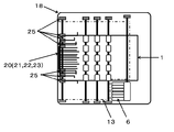
- a replacement ink tank capable of printing 10,000 sheets can be easily designed.
- the black ink tank has a lateral width of 12 cm and a depth of 22 cm
- the ink tank capacity is 2 cm ⁇ 12 cm ⁇ 22 cm and is 528 cc, that is, the printable number is 10,560.
- the depth length was 18 cm and the width was 9 cm, avoiding the printhead recovery mechanism.
- FIG. 12 and FIG. 13 show the recording apparatus 15 equipped with this large replacement ink tank.
- the replacement ink tank group 9 and its accommodating space 13 are displayed in the center, and other carriage parts, ink conduits, and paper feeding mechanisms are omitted.
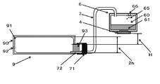
- FIG. 11 shows another embodiment of the ink disturbance buffer mechanism.
- An ink disturbance relaxation mechanism including a maze 62 is provided.
- Other numbers are the same as those in FIGS. 9 and 10.
- the extending / drawing and retracting / storing mechanisms of the recording devices 18 and 19 having the automatic extension type paper discharge tray according to the embodiment of the present invention are widely used in other fields and are not special. Incorporation of other similar automatic mechanisms into recording devices should be used as appropriate. Although it is not certain whether or not such an automatic extension / storage type paper discharge tray exists in the ink jet type recording apparatus so far, the “configuration with the paper discharge tray immediately above the ink tank outlet” of the present invention "Is a design consideration that is very user-friendly but not necessary.
- the present invention is not limited to the above embodiment, and various elemental technologies proposed for known ink jet recording apparatuses can be used according to the purpose of design to determine the height position of the replacement ink tank.
- the present invention has been mainly described for an inkjet recording apparatus as a consumer product, and its application to a business use printer has also been introduced. It can also be applied to large format printers, professional photographic printers, or industrial printers that may be costly. And even portable printers can have a significant effect if you use them, depending on your design goals.
Abstract
The present invention provides a simple high-capacity ink supply device as an ink supply system comprising two ink tanks, that is, an on-carriage ink tank integrated with a print head and a replaceable supplementary ink tank. The center value of the supplementary ink tank in the height direction is disposed H mm below the print head. When the width in the height direction thereof is ±h mm from the center value, that is, 2h mm, if the allowed negative pressure variation of a liquid chamber connected to the print head is -(P±p) mmH20, h ≤ p and |P-H| ≤ p are set so that the ink can be sucked up from the supplementary ink tank into the on-carriage ink tank just with the allowed negative pressure.
Description
家庭やオフィスで使用されるインクジェット記録装置において、プリントヘッド由来の負圧だけを用い補助装置を使わないシンプルなインク供給の基本要素条件の解明と、それにもとづく、装置本体のサイズを大きくせずに消耗品である搭載インクの容量を格段に増やす構成を有するインクジェット記録装置に関する。
Inkjet recording devices used in homes and offices, elucidating basic element conditions of simple ink supply that uses only negative pressure derived from the print head and does not use auxiliary devices, and based on that, without increasing the size of the main body of the device The present invention relates to an ink jet recording apparatus having a configuration that significantly increases the capacity of mounted ink that is a consumable.
広く普及しているインクジェット記録装置では、紙の進行方向と直行する方向に往復走査するプリントヘッドを搭載したキャリッジがあり、このキャリッジに各色のインクタンクが取り替え自在に装着されている。使えるインク量を増やすために、キャリッジ上のインクタンクとは別にもう一式のインクタンク群を持ち、そこからキャリッジ上のインクタンクにインクを供給する方式も、記録装置の使用目的に応じて採用されている。どちらの方式においても、プリントヘッドへの安定したインク供給は基本的な課題であり、そのより良い解決に様々な工夫が積み重ねられてきている。
2. Description of the Related Art A widely used inkjet recording apparatus has a carriage on which a print head that reciprocates in a direction perpendicular to the paper traveling direction is mounted, and ink tanks of various colors are mounted on the carriage in a replaceable manner. In order to increase the amount of ink that can be used, another ink tank group is provided separately from the ink tank on the carriage, and the method of supplying ink from there to the ink tank on the carriage is also adopted depending on the purpose of use of the recording device. ing. In either method, stable ink supply to the print head is a basic problem, and various ideas have been accumulated for better solutions.
コンシューマー商品ジャンル(主に家庭用やSOHO用)およびビジネスユースのインクジェット記録装置は、1990年代初頭に初めて本格的な製品が登場し、以来急速に普及し大きな市場を形成してきた。この20年間、文字品位も写真画質も格段の向上を見せ、仕様も豊かになり、デザインは洗練され、装置本体の価格もドラスチックに安くなってきた。なかんずく写真の印刷においては無くてはならない存在となっている。コンシューマー商品ジャンルのインクジェット記録装置においては、インクが無くなれば取り替えて使う消耗品であるオンキャリッジインクタンク、これはインクカートリッジと呼ばれているが、この方式が主流であり、殆どの製品に採用されている。そしてこの消耗品であるインクカートリッジは、長い間、膨大な生産量にもかかわらず、実際に印刷できるインク量も価格も殆ど変っていない。
Consumer product genres (mainly for home use and SOHO use) and business use ink jet recording devices first appeared in the early 1990s, and then rapidly spread and formed a large market. Over the past 20 years, both text quality and photographic quality have improved dramatically, the specifications have been enriched, the design has been refined, and the price of the device itself has been drastically reduced. Above all, it has become an indispensable presence in the printing of photographs. Inkjet recording devices of the consumer product genre are on-carriage ink tanks, which are consumables that can be replaced when ink runs out. These are called ink cartridges, but this method is the mainstream and is used in most products. ing. The ink cartridge, which is a consumable item, has not changed the amount of ink that can actually be printed and the price, despite the enormous production volume for a long time.
ユーザーからは「インクがすぐに無くなる」、「しかもインク代が高い」という意見が多く聞かれる。また、せっかく高性能のプリンタを買ったにもかかわらず、「できる限り使わないようにしている」、「画質を犠牲にしてでもインク使用量の少ない印刷モードでプリントすることで、とにかく我慢している」という声も聞かれる。このユーザーの要望に応えるべく、サードパーティーがインクリフィルキットやインク詰め替え商品を提供しているが、リフィルでは手を汚すことが多々あるし、詰め替え商品ではオリジナルメーカーとの間の特許紛争などが絶えない。一方、肝心のオリジナルメーカーは、ビジネスユースのプリンタでは、本体の大型化や高価格化は受け入れられるものとして、高コストの大型インクタンクシステムを導入し対応しているが、家庭用あるいはSOHO向けのコンシューマー商品プリンタでは、はっきりした対応が為されないまま推移している。適切な技術の開発は第3者が想像する以上に難しく、専門技術者ですらコンシューマー商品に適う技術の創出は難しいのであろうか。未だユーザーの不満は解消されていない。
ユ ー ザ ー Users often hear opinions that “ink will run out soon” and “ink costs are high”. In addition, even though I bought a high-performance printer, I put up with it, "I try not to use it as much as possible" and "Printing in a print mode that uses less ink even at the expense of image quality." There is also a voice saying " In order to meet this user's request, third parties provide ink refill kits and ink refill products. However, refills often get dirty, and refill products are constantly subject to patent disputes with the original manufacturer. Absent. On the other hand, the original original manufacturer has introduced a high-cost large-sized ink tank system for business use printers that accepts an increase in the size and price of the main body, but it is suitable for home use or SOHO use. In consumer product printers, there is no clear response. The development of appropriate technology is more difficult than a third party can imagine, and is it difficult for even a professional engineer to create a technology suitable for consumer products? User dissatisfaction has not yet been resolved.
代表的な例を示すと、日本市場で多く使われているインクカートリッジは、黒とイエロー、マゼンダ、シアンのカラーインク合わせて4個で構成されていて、1個1,000円強、仮に全部を交換すると5,000円近い出費となる。標準原稿・標準印刷モード(ISO/IEC2472および2471準拠)でのA4サイズへの印刷可能枚数は約500枚である。したがって1枚の印刷インク代が約10円となる。カタログにもおおむねこのようなレベルの数字が並んでいる。4色のインクを使うのであるから、平均すれば1色のインクカートリッジ当り125枚の印刷可能枚数である。価格の割にはあまりにも少ない。ユーザーからは、「これならインクが無くなったら新しいプリンタを買う方が良いではないか」と言う声すらあがっている。実際、例えば4,800円とか5,800円等の価格のプリンタが店頭に現れ、よく買われている。「インク代が高い」と言う不満は、販売上の問題でもあるので検討は置いておくとし、「インクがすぐに無くなる」と言う不満には何としてでも応えたいものである。その解決策は大容量インクカートリッジとなる筈であるので、当然1枚当りのインク代も割安とし得ることは必定である。
As a representative example, the ink cartridges that are often used in the Japanese market are composed of four color inks of black, yellow, magenta, and cyan. Replacing the cost will cost nearly 5,000 yen. The number of sheets that can be printed in A4 size in the standard manuscript / standard printing mode (ISO / IEC2472 and 2471 compliant) is about 500. Therefore, the cost of printing ink for one sheet is about 10 yen. The catalog generally contains numbers of such a level. Since four colors of ink are used, the average number is 125 printable sheets per one color ink cartridge. Too little for the price. Users even say, “If this is the case, it would be better to buy a new printer if the ink runs out.” In fact, printers with a price of, for example, 4,800 yen or 5,800 yen appear at the store and are often bought. The dissatisfaction that “ink price is high” is also a problem in sales, so we will consider it, and we would like to respond to the dissatisfaction that “ink will soon disappear”. Since the solution should be a large-capacity ink cartridge, it is of course necessary that the ink cost per sheet can be reduced.
キャリッジに各色のインクタンクが交換自在に装着されている方式をオンキャリッジインクタンク方式と呼ぶことにする。また、キャリッジ上に固定されたインクタンクとは別に、もう一式のインク補充用の交換自在のインクタンクを持ち、そこからキャリッジ上のインクタンクにインクを供給する方式をオフキャリッジインクタンク方式と呼ぶことにする。
The system in which each color ink tank is mounted on the carriage in a replaceable manner is called an on-carriage ink tank system. In addition to the ink tank fixed on the carriage, another type of replaceable ink tank for replenishing ink and supplying the ink from there to the ink tank on the carriage is called an off-carriage ink tank method. I will decide. .
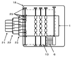
オンキャリッジインクタンク方式プリンタにおける主要構成要素の典型的な配置を、図1横断面図、図2平面図にて示す。プリンタ本体10において、1は紙カセット、2は排紙トレイであり、印刷紙は点線3で示した紙パスを通って、1から2へと搬送され排出される。その途中の印刷工程において、プリントヘッド4から情報に応じてインク滴が吐出され印刷がなされる。5は交換式オンキャリッジインクタンクである。図3に斜視図にて、この従来機におけるオンキャリッジインクタンクを交換する様子を示す。タンクの上部機構を開け、同時にキャリッジを中央に動かし、それから交換するのである。
The typical arrangement of the main components in the on-carriage ink tank type printer is shown in the cross-sectional view of FIG. 1 and the plan view of FIG. In the printer main body 10, 1 is a paper cassette, 2 is a paper discharge tray, and printed paper is conveyed from 1 to 2 through a paper path indicated by a dotted line 3 and discharged. In the middle of the printing process, ink droplets are ejected from the print head 4 according to information, and printing is performed. Reference numeral 5 denotes a replaceable on-carriage ink tank. FIG. 3 is a perspective view showing how the on-carriage ink tank in this conventional machine is replaced. Open the upper mechanism of the tank, and at the same time move the carriage to the center and then replace it.
インクタンクの代表的な大きさは、幅略1.5cm、奥行き5~7cm、高さ4~5cmであり、これが取り替え自在にキャリッジに搭載されている。文字を印字することを主眼とする黒インクは、幅が上記の倍くらいあるのが普通である。タンクの数は、この黒と、イエロー、マゼンダ、シアンの4個、あるいはフォトマゼンダ、フォトシアンを加え6個、さらに写真用の黒を加えた都合7個等の組み合わせもある。さらに写真画質の一層の向上を企図して色数を増やす構成も見られる。これらの場合、全色のタンクの幅合計は7~10cm前後になる。ここでキャリッジは、ユーザーによるインクカートリッジの交換容易性を確保するためのしっかりした機構を持っており、その厚さも加えた値である。これが紙幅(21cm)を越えて往復スキャンするのであるから、少なくとも紙幅プラス20cmの装置本体の幅が必要なのである。実際殆どのコンシューマージャンルのプリンタの横幅は40cmを優に越えている。だから、インク量を増やそうにも、これ以上インクタンクの幅を広くはし難いのである。高さと奥行きも限界に近い。また、オンキャリッジインクタンクを大きくするとキャリッジを動かすモーターへの負荷が増すことも躊躇させる要因である。キャリッジの動きの精密さはプリンタにとっては生命線なのである。
The typical size of the ink tank is approximately 1.5 cm in width, 5 to 7 cm in depth, and 4 to 5 cm in height, and this is mounted on the carriage in a replaceable manner. A black ink whose main purpose is to print characters is usually about twice as wide as the above. The number of tanks may be a combination of black and four yellow, magenta, and cyan, or six plus photo magenta and photocyan, and seven convenient plus black for photography. Furthermore, there is a configuration in which the number of colors is increased in order to further improve the picture quality. In these cases, the total width of all color tanks is around 7-10 cm. Here, the carriage has a firm mechanism for ensuring the ease of replacement of the ink cartridge by the user, and the thickness is also a value added thereto. Since this is a reciprocating scan exceeding the paper width (21 cm), at least the width of the apparatus body plus 20 cm is necessary. In fact, the width of most consumer genre printers is well over 40cm. Therefore, it is difficult to increase the width of the ink tank any more in order to increase the amount of ink. The height and depth are close to the limit. In addition, increasing the on-carriage ink tank also increases the load on the motor that moves the carriage. The precision of carriage movement is a lifeline for printers.
このような事情からか、オンキャリッジインクタンク方式では長年インク容量は増やされていない。なお、前述の幅広の黒インクタンクと普通の横幅のイエロー、マゼンダ、シアン、都合4色のシステムの場合は、合計の横幅は7cmくらいである。この場合、紙幅プラス14cmの幅方向の長さが必要である。このような比較的幅狭のインクカートリッジ群の製品においても、インク量の増量は何ら手つかずのまま推移している。
For these reasons, the on-carriage ink tank method has not increased the ink capacity for many years. In the case of the above-described wide black ink tank and the normal width of yellow, magenta, cyan, and a system of four colors, the total width is about 7 cm. In this case, a width in the width direction of 14 cm is required. Even in such a relatively narrow product group of ink cartridges, the increase in the amount of ink remains unchanged.
上記事例のインクタンクの内容量は30cc強である。オンキャリッジインクタンクは実質的にはプリントヘッドの上方置きであり、基本的には水頭圧がプリントヘッドにかかり、よほど浅いインクタンクでないかぎり、何か対処しなければインクがプリントヘッドから漏れてしまう。そのためにスポンジ状の詰め物をしたり、迷路を作ったり弁を設けたりして、プリントヘッドからのインクのボタ落ちを防いでいる。1例が引用文献1:特開平07-068773に見られる。この技術はその後改良され実際の製品で使われていると考えられるが、この詰め物のためインクカートリッジ体積の利用効率は半分近くまで落ち、有効インク量は例えば15ccくらいになる。実際の使われ方であるレポートや手紙文あるいはレシピやネット情報のコピーなどの使用では、前記標準原稿印刷に比し半分くらいのインク消費量であり、1枚当たりのインク消費量は概略0.05ccである(実際に印字に使われるインク量とメンテナンスに使われるインク量の合算からの換算値である)。したがって計算上は略300枚/インクカートリッジ1個の印字が可能と言うわけである。これは多くのユーザーの実感の上限値に合致している。(本提案では以後、上記の1枚当たりのインク消費量は0.05ccを用いて説明を続ける)
The content of the ink tank in the above example is over 30cc. The on-carriage ink tank is essentially located above the print head, and basically the head pressure is applied to the print head, and unless it is a very shallow ink tank, ink will leak out of the print head if no action is taken . Therefore, sponge-like stuffing, a maze, or a valve is provided to prevent ink from dropping from the print head. One example can be found in cited document 1: Japanese Patent Application Laid-Open No. 07-068773. Although this technique is later improved and is considered to be used in actual products, the use efficiency of the ink cartridge volume drops to almost half due to this filling, and the effective ink amount is about 15 cc, for example. In actual use, such as reports, letters, recipes, and copies of net information, the ink consumption is about half that of the standard manuscript printing, and the ink consumption per sheet is approximately 0. It is 05 cc (the converted value from the sum of the ink amount actually used for printing and the ink amount used for maintenance). Therefore, it can be said that printing of approximately 300 sheets / one ink cartridge is possible in calculation. This is consistent with the upper limit of the actual feeling of many users. (In this proposal, the description will be continued using 0.05 cc of ink consumption per sheet)
以上のことから課題は明確である。コンシューマー商品ジャンルのインクジェットプリタで、本体を大きくしないでかつシンプルな、だからコストの上がらないインク容量を増やす方法の創出が待たれているのである。オンキャリッジインクタンク方式では、インク増量には前記のように限度がある。解をオフキャリッジインクタンク方式に求めなければならない。さらに装置本体の横幅にも課題がある。家庭やSOHOの狭い机上やオフィスでは、高さで例えば18cmが23cmになっても特段のことは無いが、横幅が例えば43cmが48cmになることは占有場所が広がりかなり困ることである。同ジャンルのレーザープリンタよりも幅広となってしまう。本体の横幅を広げるようなオフキャリッジインクタンクの配置は採らないことを課題に加える。
From the above, the issues are clear. With the inkjet printer of the consumer product genre, there is a need to create a simple method that does not increase the size of the main body and thus increases the ink capacity without increasing the cost. In the on-carriage ink tank system, the amount of ink increase is limited as described above. The solution must be found in an off-carriage ink tank system. There is also a problem with the width of the apparatus body. On a desk or office with a narrow home or SOHO, there is nothing special even if the height is, for example, 18 cm becomes 23 cm. However, if the width is 43 cm, for example, 48 cm, the occupied area is widened and it is quite difficult. It will be wider than laser printers of the same genre. It is added to the problem that an off-carriage ink tank is not arranged so as to widen the width of the main body.
オフキャリッジインクタンクの配置場所で常識的に良いとされているのは、プリントヘッドの下方である。インクタンクがプリントヘッドの上方にあると、インクタンクの水頭圧によってプリントヘッドからインクが漏れだすいわゆるボタ落ちが生じる。その対応に工夫が要る。下方置きではボタ落ちの心配が無い、だから簡便な機構で済ませることができる、と言われている。
It is the lower part of the print head that is commonly considered good in the location of the off-carriage ink tank. When the ink tank is located above the print head, so-called dripping occurs that ink leaks from the print head due to the water head pressure of the ink tank. Ingenuity is required for the correspondence. It is said that there is no fear of falling down when placed down, so a simple mechanism can be used.
しかし実際には幾つかの問題があり様々な工夫がなされている。公知例として特許文献2特開2001-138541号公報、同3特開2010-228237号公報、同4特開2009-226026号公報が参考になる。特開2009-226026号公報では、ポンプによりバッファー室(サブタンクと呼んでいる)を負圧状態に減圧し印刷の安定を図り、必要に応じバッファー室を正圧状態に加圧し貯留されたインクをプリンタヘッドから自動的に送出させるようにしている。何れにおいても、プリントヘッド由来の負圧を用いて自動的に吸い上げることができるのは3cm前後の深さまでであり、これを越える深さでは吸い上げポンプが必要となる。ポンプを使うとなると、必然的にセンサーや切換弁や制御機器などが必要であり、コストのかかる構成となる。
However, there are actually some problems and various innovations have been made. As known examples, JP-A-2001-138541, JP-A-2010-228237, JP-A-2009-226026 and JP-A-2009-226026 can be referred to. In JP-A-2009-226026, a buffer chamber (called a sub-tank) is decompressed to a negative pressure state by a pump to stabilize printing, and if necessary, the buffer chamber is pressurized to a positive pressure state to store the stored ink. The printer head automatically sends it out. In any case, it is possible to suck up automatically using a negative pressure derived from the print head up to a depth of about 3 cm, and a suction pump is required at a depth exceeding this. When a pump is used, a sensor, a switching valve, a control device, and the like are inevitably required, resulting in a costly configuration. *
市販品の中には図4、図5に模式図的に示すような、紙送り機構とプリントヘッドの回復機構(図のオンキャリッジインクタンク6の下部、番号12で示す)を避けた記録装置11の片側に寄った場所に交換用オフキャリッジインクタンクを設けたものが見られる。番号8で示す場所である。7は両インクタンクを結ぶ可撓性インク導管である。この構成では、記録装置本体の奥側方向には交換用オフキャリッジインクタンクをいくばくかは長くでき、収容インク量を増やすことができる。しかしこのような片側寄せの置き方では、インクタンクの横幅は本体幅に影響するため、それほどは大きくできない。また色数も増やしにくい。実際、市販されているものは4色である。本体幅をもう少し増やしても良いとするならば色数を増やすことはできるが、“拡張自由度”がある場所とは言えない。
Among commercially available products, a recording apparatus that avoids a paper feed mechanism and a print head recovery mechanism (indicated by reference numeral 12 below the on-carriage ink tank 6 in the figure) as schematically shown in FIGS. 11 can be seen in which a replacement off-carriage ink tank is provided at a location on one side of the 11. This is the place indicated by the number 8. Reference numeral 7 denotes a flexible ink conduit connecting the two ink tanks. In this configuration, the replacement off-carriage ink tank can be somewhat longer in the rear side direction of the recording apparatus main body, and the amount of stored ink can be increased. However, in such a side-by-side placement, the width of the ink tank affects the width of the main body and cannot be so large. Also, it is difficult to increase the number of colors. In fact, there are four colors on the market. The number of colors can be increased if the width of the main body can be increased a little, but it cannot be said that there is “extended freedom”.
ポンプなどの力を用いないインク収納量大容量化の回答の一つは、交換用インクタンクをプリントヘッドの上方に配置し、このタンク内のインクがもたらすプリントヘッドへの水頭圧を制御する水頭圧制御機構をオンキャリッジインクタンク内に設け、プリントヘッドに連なる液室の負圧変動許容範囲に対応した交換用インクタンクの高さ幅とする方法である。このインク供給系はオフキャリッジインクタンクの高さ幅は制約されているが、記録装置本体幅いっぱいに配置できる「拡張自由度」を有している。また記録装置本体の奥側方向にも長いスペースが得られるものである。ただし、小型の弁のような簡単なものではあるが水頭圧制御機構を必要とする。
One of the answers to increase the ink storage capacity without using a force such as a pump is to place a replacement ink tank above the print head and control the head pressure on the print head caused by the ink in this tank. In this method, a pressure control mechanism is provided in the on-carriage ink tank, and the height of the replacement ink tank is set so as to correspond to the negative pressure fluctuation allowable range of the liquid chamber connected to the print head. This ink supply system has an “expansion degree of freedom” that can be arranged to fill the entire width of the printing apparatus main body although the height width of the off-carriage ink tank is restricted. In addition, a long space can be obtained in the rear side direction of the recording apparatus main body. However, although it is as simple as a small valve, it requires a hydraulic head pressure control mechanism.
上記の様々な工夫の中で、本発明は、交換用オフキャリッジインクタンクのプリントヘッド下方配置に関するものであり、(1)収納インクの大容量化が簡単で、収納インク量や色数の拡張自由度を有し、(2)インクタンク交換においてはユーザーフレンドリーであり、(3)本体の横幅を広げないで、(4)コンシューマー商品たらしめるシンプルで安価な構成で実現することを目的とするものである。大前提としてプリントヘッドからのインクボタ落ちが無くかつインク吐出を阻害しない安定したインク供給性能を有するものである。
Among the various devices described above, the present invention relates to the disposition of the replacement off-carriage ink tank below the print head, and (1) it is easy to increase the capacity of the stored ink and expand the stored ink amount and the number of colors. It has a degree of freedom, (2) is user-friendly in ink tank replacement, (3) does not widen the main body, and (4) aims to realize a simple and inexpensive configuration that makes it a consumer product. Is. The main premise is that the ink does not fall off from the print head and has stable ink supply performance that does not hinder ink ejection.
本発明は上記目的を達成するために、第1の課題解決手段として、インクジェット方式記録装置において、少なくとも、プリントヘッドと一体化したオンキャリッジインクタンクと、交換可能な補充用インクタンクと、この補充用インクタンクからインクをオンキャリッジインクタンクに導く可撓性インク導管とから成るインク供給系であること、補充用インクタンクをプリントヘッドの下方に配置し、その中心位置をプリントヘッドから下方にHmmその高さ方向の幅を±hmmすなわち2hmmとするとき、プリントヘッドに連なる液室の負圧変動許容値が-(P±p)mmH2Oであるならば、h≦pかつ|P-H|≦pとすることによりこの許容負圧のみで補充用インクタンクからオンキャリッジインクタンクにインクを吸い上げることを特徴とするインクジェット方式記録装置である。
In order to achieve the above object, according to the present invention, as a first problem solving means, in an ink jet recording apparatus, at least an on-carriage ink tank integrated with a print head, a replaceable refill ink tank, and the refill The ink supply system is composed of a flexible ink conduit that guides ink from the ink tank to the on-carriage ink tank, the replenishment ink tank is arranged below the print head, and its central position is Hmm below the print head. If the width in the height direction is ± hmm, that is, 2hmm, and the negative pressure fluctuation allowable value of the liquid chamber connected to the print head is − (P ± p) mmH2O, h ≦ p and | PH | ≦ By setting p, ink is sucked from the replenishment ink tank to the on-carriage ink tank only by this allowable negative pressure. It is a Kujetto system recording apparatus.
第2の課題解決手段は、第1の課題解決手段において、特に、h=pかつH=Pであることを特徴とするインクジェット記録装置である。
The second problem solving means is an ink jet recording apparatus characterized in that h = p and H = P in the first problem solving means.
さらに課題解決手段3として、前記課題解決手段1および2において、交換用インクタンクの配置条件を、プリントヘッド下方であってh≦pかつ|P-H|≦pあるいは特にh=pかつH=Pであるという条件に加え、記録装置本体の横方向および奥行き方向において、プリントヘッドの回復機構と紙送り機構を避けた全域に亘る空間内の任意位置とすることを特徴とするインクジェット記録装置である。
Further, as the problem solving means 3, in the above problem solving means 1 and 2, the replacement ink tank is placed under the condition that h ≦ p and | PH | ≦ p or particularly h = p and H = below the print head. In addition to the condition that it is P, in the lateral direction and the depth direction of the recording apparatus main body, it is an arbitrary position in the space over the entire area avoiding the print head recovery mechanism and the paper feeding mechanism. is there.
課題解決手段4は、課題解決手段1、2および3において、交換可能な補充用インクタンクの配置空間の直上に位置する排紙トレイが、記録装置休止中あるいは停止中は記録装置本体内に自動的に引き込まれ格納され、記録装置作動中は自動的に本体内の格納位置から伸長あるいは繰り出されることを特徴とするインクジェット記録装置である。
The problem solving means 4 is the problem solving means 1, 2, and 3, in which the paper discharge tray positioned immediately above the space for arranging the replaceable refilling ink tank is automatically placed in the recording apparatus main body when the recording apparatus is stopped or stopped. The ink jet recording apparatus is automatically retracted and stored, and automatically extends or retracts from the storage position in the main body during operation of the recording apparatus.
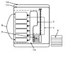
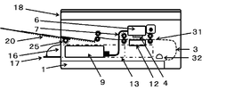
第1の課題解決手段による作用は次のとおりである。本発明の記録装置14の主要構成要素の配置を模式図6(横断面図),7(平面図)にて示す。一点鎖線13で示す空間が、本発明で規定する下置きオフキャリッジインクタンク(交換用インクタンク)9の収納可能空間である。詳しくは後述する。
The operation of the first problem solving means is as follows. The arrangement of the main components of the recording apparatus 14 of the present invention is schematically shown in FIGS. 6 (transverse sectional view) and 7 (plan view). A space indicated by an alternate long and short dash line 13 is a space that can store the lower off-carriage ink tank (replacement ink tank) 9 defined in the present invention. Details will be described later.
先ず交換用インクタンク9のプリントヘッド下方配置に関する諸条件を厳密に考究し、以下のような必要十分条件を得た。交換用インクタンクの高さ方向の中心位置をプリントヘッドからHmm下方とする。そしてその高さ方向の幅を中心位置から±hmm、すなわち2hmmとする。(H-h)mmがインク満杯時のインクの高さであり、(H+h)mmはインクが底をつく直前の高さである。また、プリントヘッドからインクを漏らさず(いわゆるボタ落ちをさせず)かつ吐出が問題となるほど高くない負圧の範囲を-(P±p)mmH2Oとする。
First, various conditions regarding the disposition of the replacement ink tank 9 below the print head were strictly studied, and the following necessary and sufficient conditions were obtained. The center position of the replacement ink tank in the height direction is set to be Hmm below the print head. The width in the height direction is ± hmm from the center position, that is, 2 hmm. (H−h) mm is the ink height when the ink is full, and (H + h) mm is the height immediately before the ink reaches the bottom. Further, a negative pressure range that does not leak ink from the print head (so-called no dropping of the ink) and is not so high as to cause ejection becomes − (P ± p) mmH 2 O.
(A)必須条件1:負圧が最低まで弱くなったら{すなわち-(P-p)mmH2Oの時}、インクの最も汲み上げ易い/流入し易い交換タンク最上位位置{すなわち下方に(H-h)mmの時}からも、もうこれ以上は吸い上げない/流入させない。もって負圧のさらなる低下をもたらしインクのボタ落ちを起こすことをさせない。この条件は次のように表わすことができる。
H-h≧P-p・・・・・(1)
説明の簡便化のため、インクの密度は水と同じ1とした。実際にも殆どが水であるインクの密度は近似しており、このように扱って問題は無い。 (A) Mandatory condition 1: When the negative pressure is weakened to the lowest level (ie, when-(Pp) mmH 2 O), the top position of the replacement tank {i.e., downward (H No further suction / inflow from -h) mm}. As a result, the negative pressure is further reduced, and the ink does not fall off. This condition can be expressed as follows.
Hh ≧ Pp (1)
In order to simplify the explanation, the density of the ink is set to 1 which is the same as that of water. Actually, the density of ink, which is mostly water, is approximate, and there is no problem in handling in this way.
(B)必須条件2:負圧が最大では{すなわち-(P+p)mmH2Oの時}、インクの最も汲み上げ難い交換タンク最底部位置{すなわち下方(H+h)mmの時}からもインクを吸い上げる。 この条件は次のように表わすことができる。
H+h≦P+p・・・・・(2) (B) Indispensable condition 2: When negative pressure is maximum {ie, when-(P + p) mmH 2 O}, ink is also sucked up from the bottom position of the replacement tank that is most difficult to pump up ink (ie when it is below (H + h) mm). . This condition can be expressed as follows.
H + h ≦ P + p (2)
上記の式(1)および(2)から
h-p ≦P-H ≦p-h・・・・・(3)
が導かれる。これからさらに、
h≦p+(P-H)かつh≦p-(P-H)、すなわち
h≦p-|P-H|、ただし p-|P-H|≧0
あるいはより端的に、
h≦pかつ|P-H|≦p ・・・・・(4)
が導かれる。すなわち交換用インクタンクの高さ幅2hは負圧の許容変動幅の2p以下であり、加えてタンク位置の中心値Hと許容負圧の中心値Pの差が許容変動幅の1/2のp以下となるのである。そしてこの条件さえ満たせば、(A)最も吸い上げやすい補充用インクタンク最上位部からインクを吸い上げた時でも、プリントヘッド周りの負圧を許容最低値以下に下げてしまうことも無く、したがってインクのボタ落ちをひき起すということも無い、(B)吸引ポンプ等の補助動力や補助装置を用いないで、プリントヘッドに連なる液室の許容負圧-(P±p)mmH2Oのみで補充用インクタンクからオンキャリッジインクタンクにインクを吸い上げることができる、この2基本要素条件がみたされるのである。 From the above formulas (1) and (2), hp ≤ PH ≤ ph (3)
Is guided. From now on,
h ≦ p + (P−H) and h ≦ p− (P−H), that is, h ≦ p− | P−H |, where p− | P−H | ≧ 0
Or more simply,
h ≦ p and | PH | ≦ p (4)
Is guided. That is, theheight width 2h of the replacement ink tank is 2p or less of the allowable fluctuation range of the negative pressure, and the difference between the center value H of the tank position and the central value P of the allowable negative pressure is 1/2 of the allowable fluctuation range. p or less. As long as this condition is satisfied, (A) even when ink is sucked up from the top of the replenishing ink tank that is most easily sucked up, the negative pressure around the print head is not lowered below the allowable minimum value. (B) Ink tank for replenishment with only the allowable negative pressure of the liquid chamber connected to the print head-(P ± p) mmH2O, without using auxiliary power or auxiliary equipment such as a suction pump. Thus, these two basic element conditions that allow ink to be sucked into the on-carriage ink tank are satisfied.
h-p ≦P-H ≦p-h・・・・・(3)
が導かれる。これからさらに、
h≦p+(P-H)かつh≦p-(P-H)、すなわち
h≦p-|P-H|、ただし p-|P-H|≧0
あるいはより端的に、
h≦pかつ|P-H|≦p ・・・・・(4)
が導かれる。すなわち交換用インクタンクの高さ幅2hは負圧の許容変動幅の2p以下であり、加えてタンク位置の中心値Hと許容負圧の中心値Pの差が許容変動幅の1/2のp以下となるのである。そしてこの条件さえ満たせば、(A)最も吸い上げやすい補充用インクタンク最上位部からインクを吸い上げた時でも、プリントヘッド周りの負圧を許容最低値以下に下げてしまうことも無く、したがってインクのボタ落ちをひき起すということも無い、(B)吸引ポンプ等の補助動力や補助装置を用いないで、プリントヘッドに連なる液室の許容負圧-(P±p)mmH2Oのみで補充用インクタンクからオンキャリッジインクタンクにインクを吸い上げることができる、この2基本要素条件がみたされるのである。 From the above formulas (1) and (2), hp ≤ PH ≤ ph (3)
Is guided. From now on,
h ≦ p + (P−H) and h ≦ p− (P−H), that is, h ≦ p− | P−H |, where p− | P−H | ≧ 0
Or more simply,
h ≦ p and | PH | ≦ p (4)
Is guided. That is, the
以上が交換用インクタンクに求められる条件であるが、我々の目的はこのインクタンクの高さ幅を少しでも大きくし収納インク量を増やしたいのであるから、hは最大値のh=pそしておのずからH=Pとするのがより好ましい。これが第2の課題解決手段である。例えば
負圧変動許容値が-25mm±10mmH2Oであれば、交換用インクタンクの高さ2hは2p相当の20mmであることを示唆している。また、h=pとするためにはP-Hはゼロの数字以外であってはならない。すなわちP=H(この事例ではH=25mm)とすべきなのである。そのうえで、紙送り機構との干渉を避ける等の理由からインクタンク上部位置を下げなければならないこともあろう。そのためにやむなくh<pとすることもある。 The above is the condition required for the replacement ink tank. Since our purpose is to increase the height of the ink tank as much as possible to increase the amount of stored ink, h is the maximum value h = p and naturally More preferably, H = P. This is the second problem solving means. For example, if the negative pressure fluctuation allowable value is −25 mm ± 10 mm H 2 O, it indicates that the replacementink tank height 2 h is 20 mm corresponding to 2 p. Also, in order for h = p, PH should not be a number other than zero. That is, P = H (H = 25 mm in this case) should be set. In addition, the upper position of the ink tank may have to be lowered to avoid interference with the paper feed mechanism. Therefore, h <p may be unavoidable.
負圧変動許容値が-25mm±10mmH2Oであれば、交換用インクタンクの高さ2hは2p相当の20mmであることを示唆している。また、h=pとするためにはP-Hはゼロの数字以外であってはならない。すなわちP=H(この事例ではH=25mm)とすべきなのである。そのうえで、紙送り機構との干渉を避ける等の理由からインクタンク上部位置を下げなければならないこともあろう。そのためにやむなくh<pとすることもある。 The above is the condition required for the replacement ink tank. Since our purpose is to increase the height of the ink tank as much as possible to increase the amount of stored ink, h is the maximum value h = p and naturally More preferably, H = P. This is the second problem solving means. For example, if the negative pressure fluctuation allowable value is −25 mm ± 10 mm H 2 O, it indicates that the replacement
以上の2必須条件をもって十分な性能、すなわち「ボタ落ちがなくかつ最低部からも汲み上げることができる」ことが得られるのである。この原理的な検討から、いくら下からでもインクを組みあげられる、と言うわけにはいかないことが分かる。交換用インクタンクの最大高さ位置は、ヘッド位置から下方の(P-p)mmから(P+p)mmまでであり、タンクの高さ幅は最大2pmmである。 この制約条件はかなり「狭い」あるいは「窮屈」なものである。だからといってサブタンク位置や高さ幅を広げるとポンプ等の補助動力を必要とする。そのようなインク供給システムは本発明と関わらない領域である。たとえ高さ方向の条件が厳しくとも、これさえ丁寧に順守すれば、得られる他の条件はきわめて魅力的なものであるからである。
It is possible to obtain sufficient performance with the above two essential conditions, that is, “there is no dropping and pumping from the lowest part”. From this principle study, it can be seen that it cannot be said that ink can be assembled from below. The maximum height position of the replacement ink tank is from (P−p) mm to (P + p) mm below the head position, and the maximum height of the tank is 2 pmm. This constraint is quite “narrow” or “tight”. However, if the sub-tank position and height are widened, auxiliary power such as a pump is required. Such an ink supply system is an area not relevant to the present invention. This is because even if the conditions in the height direction are severe, other conditions that can be obtained are very attractive if they are carefully followed.
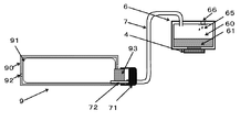
図9と図10を用いて具体的に説明する。交換用インクタンク9は連結用シール部材93を具備している。プリンタ本体の連結機構71にはニードル72が設けられている。交換用インクタンク9が連結機構71に装着されると、インクはニードル72から可撓性インク導管7を介してオンキャリッジインクタンク6のインク室60に連通する。このとき不要な空気の混入を防ぐ手段や、その前にインクが空になったことを知らせる仕組み、インクタンク交換時シーケンス(予備吐出やヘッドクリーニング等)など、関連する諸要素が必要であるが、多くのすぐれた公知技術から適宜援用すればよい。本発明の骨格に絞って説明を続ける。
This will be specifically described with reference to FIG. 9 and FIG. The replacement ink tank 9 includes a connecting seal member 93. The connecting mechanism 71 of the printer body is provided with a needle 72. When the replacement ink tank 9 is attached to the connection mechanism 71, the ink communicates from the needle 72 to the ink chamber 60 of the on-carriage ink tank 6 through the flexible ink conduit 7. At this time, it is necessary to have various related elements such as a means to prevent unnecessary air from entering, a mechanism for notifying that ink has been emptied before that, and an ink tank replacement sequence (preliminary ejection, head cleaning, etc.). These may be appropriately incorporated from many excellent known techniques. The description will be continued focusing on the skeleton of the present invention.
オンキャリッジインクタンク6のインク室60の内部では、プリント動作による激しい往復運動によってインクは常に擾乱状態にある。このインク状態が直接プリントヘッドに伝わると安定した吐出ができなくなってしまう。そこで番号61で示すような、プリントヘッドを保護しインクの乱れる動きを緩和させる緩衝機構を設ける。これは連通多孔質材、例えばスポンジや繊維の詰め物などを用いる。あるいは後述の迷路状の緩衝機構も有効である。
In the ink chamber 60 of the on-carriage ink tank 6, the ink is always in a disturbed state due to intense reciprocation by the printing operation. If this ink state is directly transmitted to the print head, stable ejection cannot be performed. Therefore, a buffer mechanism for protecting the print head and mitigating the turbulent movement of the ink as shown by reference numeral 61 is provided. This uses a continuous porous material, such as a sponge or fiber stuffing. Alternatively, a maze-like buffer mechanism described later is also effective.
またインク室60の中では混入気泡の問題が内在している。すなわちインク室60に何らかの理由(溶融気体、インクタンク交換時の混入気体等)で気泡が混在すると、液温が上昇した時などに膨張し、意図せずプリントヘッド4からのインクボタ落ちを惹起する。気泡を図9および図10に番号65で例示的に示した。このような不都合を防ぐために「気体の放出、あるいは過剰な正圧の放出」を行う機構66が必要である。インクジェットプリンタでは、基本的には全てのオンキャリッジインクタンクにこの機構が組み込まれている。
Also, in the ink chamber 60, the problem of mixed bubbles is inherent. That is, if bubbles are mixed in the ink chamber 60 for some reason (melted gas, mixed gas at the time of ink tank replacement, etc.), it expands when the liquid temperature rises, etc., causing the ink head to drop unintentionally from the print head 4. . Bubbles are exemplarily shown in FIG. 9 and FIG. In order to prevent such an inconvenience, a mechanism 66 that performs “gas release or excessive positive pressure release” is necessary. In an inkjet printer, this mechanism is basically incorporated in all on-carriage ink tanks.
交換用インクタンク9からのインクの送出をスムーズにするためには、送出に伴う負圧がここに発生してはいけない。例えば取扱性を容易にするためハードなインク容器90を用い、その中に柔らかくインク送出にしたがって自然にしぼんで行くようなインク袋91を使う、などの工夫が必要である。ハードインク容器90には空気を取り入れる孔92を設けておくことが、負圧発生を防ぐために肝要である。これ以外にも同様の性能を持つ機構が多く提案されている。
In order to make the delivery of ink from the replacement ink tank 9 smooth, negative pressure accompanying the delivery should not be generated here. For example, in order to facilitate handling, a device such as using a hard ink container 90 and using an ink bag 91 that is soft and deflated naturally as the ink is delivered is required. It is important to provide a hole 92 for taking in air in the hard ink container 90 in order to prevent the generation of negative pressure. Many other mechanisms with similar performance have been proposed.
交換用インクタンク9の収納可能場所は図6、図7あるいは図8の一点鎖線13で示す、紙カセット1の上方でありかつプリントヘッド直下の紙搬送路31の下方の空間である。ここに収める交換用インクタンク9の高さ幅は上記のように最大で2pmm相当であり、必ずしも大きな値では無い。インク性状やプリントヘッド形状により決まる負圧変動許容幅2pにもよるが、高くても40mm前後である。この空間を確保するために、プリントヘッド直下の紙搬送路31は従来の記録装置に比し高めの構成にしておく必要がある。ただし、オンキャリッジインクタンクは、ここにインクを貯め込む目的では無いので小さくて済む。高さも横幅も、必要なら奥行き幅も、である。したがって、プリントヘッド直下の紙搬送路31を従来の記録装置に比し高めた構成でも、記録装置としてはその高さは従来機と殆ど変らない。
The place where the replacement ink tank 9 can be stored is a space above the paper cassette 1 and below the paper transport path 31 directly below the print head, as indicated by a dashed line 13 in FIG. The height width of the replacement ink tank 9 housed here is equivalent to 2 pmm at the maximum as described above, and is not necessarily a large value. Although it depends on the negative pressure fluctuation allowable width 2p determined by the ink properties and the print head shape, it is at most about 40 mm. In order to secure this space, the paper conveyance path 31 directly under the print head needs to be configured higher than that of the conventional recording apparatus. However, the on-carriage ink tank is small because it is not intended to store ink here. Height, width, and depth if necessary. Therefore, even if the paper conveyance path 31 directly under the print head is higher than that of the conventional recording apparatus, the height of the recording apparatus is almost the same as that of the conventional apparatus.
交換用インクタンク9の収納可能場所、一点鎖線13であるが、もう一つの制約事項は、プリントヘッドの回復機構(図6のオンキャリッジインクタンクの下部、番号12で示す)を避けることである。また駆動伝達機構は可能な限り外装部側に配すること、紙搬送のための送りローラーなども可能な限り小径にする、等の配慮が必要である。これらの設計的配慮をすることによって、記録装置の横幅一杯に近い広い交換用インクタンク9の収納可能スペース13が得られる。
The place where the replacement ink tank 9 can be accommodated is the one-dot chain line 13, but another limitation is to avoid the print head recovery mechanism (lower part of the on-carriage ink tank in FIG. 6, indicated by reference numeral 12). . In addition, it is necessary to consider that the drive transmission mechanism should be arranged on the exterior portion side as much as possible and that the feed roller for paper conveyance should be as small as possible. By taking these design considerations into consideration, it is possible to obtain a space 13 in which the replacement ink tank 9 can be accommodated, which is close to the full width of the recording apparatus.
奥行き方向の制約は紙のピックアップローラー図6の番号32である。収納可能スペース13は、最大この位置まで伸ばせる。このようにして、この交換用インクタンク9の収納可能場所、一点鎖線空間13は、高さこそ大きくは無いが、記録装置の横幅ほぼ一杯の横幅と長い奥行きから成る巨大な空間として創出できたのである。
The restriction in the depth direction is the paper pickup roller No. 32 in FIG. The stowable space 13 can be extended up to this position. In this way, the place where the replacement ink tank 9 can be stored, the one-dot chain line space 13 is not high in height, but can be created as a huge space having a full width and a long depth of the recording apparatus. It is.
以上が本発明の課題解決手段の基本原理であり、作用の説明であるが、これによる効果は以下のとおりである。(1)交換用インクタンクをプリントヘッドよりも下方に配置する構成において、広い配置スペースと拡張自由度を担保し、ゆいつ上記条件“h≦pかつ|P-H|≦p”を守るだけで良いシンプルな構成が可能となった。すなわち、インク供給のために、これまで提案されてきた他の配置や方法で必要とされているバッファー室や汲み上げポンプは不要である。これらに関わるインク移送手段、センサーや切り替え弁、フランジ等々の機械要素および制御回路も不要である。インクは単にプリントヘッド由来の負圧にしたがって汲み上げられる。シンプルで低コストであり、にもかかわらず必要機能を確実に実現できる。
The above is the basic principle of the problem-solving means of the present invention and the explanation of the operation. The effects of this are as follows. (1) In the configuration in which the replacement ink tank is arranged below the print head, a wide arrangement space and expansion flexibility are ensured, and only the above conditions “h ≦ p and | PH | ≦ p” are observed. A good and simple configuration is possible. In other words, a buffer chamber and a pumping pump that are required in other arrangements and methods that have been proposed so far are not necessary for supplying ink. Mechanical elements such as ink transfer means, sensors, switching valves, and flanges and control circuits related to these are also unnecessary. Ink is simply pumped according to the negative pressure from the printhead. It is simple and low-cost, but the necessary functions can be realized reliably.
(2)本発明の目的は、記録装置の大きさを大きくしないことでもある。前述のように代表的な、20年に亘り変化なく使われてきたオンキャリッジインクタンクの高さは、少しでも多くのインクを搭載したい、しかしインクのボタ落ちは避けねばならない、という二律背反性から略40mmないし50mmの高さであり続けている。そして水頭圧を制御する簡単ではあるが何らかの臓物が入っている。本発明によれば、プリントヘッドと一体と成るオンキャリッジインクタンクは、ここにインクを貯め込む目的では無いのでそれらよりは小さくて済む。その高さは10mm~15mm程度の高さで充分である。従来機に比し30mmないし40mm低くて済み、その分プリントヘッド直下の紙搬送路31を上方向に持ち上げ、下方のスペースを広げることができる。例えば収納可能空間13の高さを30mmとり、その中に例えば20mm高さ幅の交換用インクタンクを装着できるようにする。例えば幅40mm、奥行き80mmとすれば(全てインクタンクの内寸法表示である)、64ccのインク容量となる。1,280枚を超えるプリントが可能なインク量である(64cc/0.05cc=1,280)。これが従来機とほとんど同じ装置高さの中でのユーザー不満に対する回答である。
(2) An object of the present invention is also not to increase the size of the recording apparatus. As mentioned above, the height of the on-carriage ink tank that has been used without change for 20 years is a trade-off that you want to install as much ink as possible, but you must avoid ink dropping. The height continues to be approximately 40 mm to 50 mm. And there is some simple organs to control the water head pressure. According to the present invention, the on-carriage ink tank integrated with the print head is not intended to store ink here, so it can be smaller. A height of about 10 mm to 15 mm is sufficient. Compared with the conventional machine, it is 30 mm to 40 mm lower, and accordingly, the paper conveyance path 31 directly below the print head can be lifted upward to widen the lower space. For example, the storage space 13 has a height of 30 mm, and a replacement ink tank having a height of, for example, 20 mm can be mounted therein. For example, if the width is 40 mm and the depth is 80 mm (all are the internal dimensions of the ink tank), the ink capacity is 64 cc. The amount of ink that can be printed exceeds 1,280 sheets (64 cc / 0.05 cc = 1,280). This is the answer to user dissatisfaction in almost the same device height as the conventional machine.
(3)記録装置の横幅を小さくできる。繰り返しではあるが、前項で「オンキャリッジインクタンクは、ここにインクを貯め込む目的では無いので小さくて済む」と記したが、これは高さだけでは無い。横幅も小さくできる。例えば数mmに、とにかく1cm以内に、である。この数字は例示であるが、インクの色数が増えれば増えるほど、記録装置本体幅には2倍で効いてくるのであるから、効果は大きいことが理解できるはずである。参考として、図7の右側に従来機のインクタンク5を点線で示した。この従来機の大きさは同図の点線10である。たんなる模式図であるが、往復するオンキャリッジインクタンクの幅が記録装置本体の横幅に大きく効いてくることが視覚的に理解できよう。製品のサイズは他にも制約条件があり設計マターではあるが、小さくし得る自由度を担保できることは大きな効用である。
(3) The width of the recording device can be reduced. Although it is repeated, it was described in the previous section that “the on-carriage ink tank is small because it is not intended to store ink here”, but this is not only the height. The width can be reduced. For example, within a few mm, and within 1 cm anyway. This number is merely an example, but it should be understood that the greater the number of ink colors, the greater the effect because the effect on the recording apparatus main body width is doubled. For reference, the ink tank 5 of the conventional machine is indicated by a dotted line on the right side of FIG. The size of this conventional machine is a dotted line 10 in FIG. Although it is a simple schematic diagram, it can be visually understood that the width of the reciprocating on-carriage ink tank greatly affects the lateral width of the recording apparatus main body. There are other constraints on the size of the product, and it is a design matter, but the ability to ensure a small degree of freedom is a major utility.
交換用インクタンクの典型的な例(例えば黒用タンク1個、カラー用タンク5個)では、文字用の黒を大型にし、例えば横幅60mmとする。他の色用インクタンク幅は40mmとする。合計の横幅は、60+40x5=260mmである。これは、紙幅+オンキャリッジインクタンク幅x2に近似し、越えるものではない。同じ6色搭載の従来機より少なくとも5cm以上幅狭の製品が作れるのである。先にカラーインクタンクの印刷可能枚数を示したが、この事例の文字用の黒インクタンクの容量は60mmx20mmx80mm=96cc。 すなわち、96cc/0.05cc=1,920(枚)印刷可である。
In a typical example of the replacement ink tank (for example, one black tank and five color tanks), the black for characters is made large, for example, 60 mm wide. The ink tank width for other colors is 40 mm. The total lateral width is 60 + 40 × 5 = 260 mm. This approximates and does not exceed the paper width + on-carriage ink tank width x2. A product that is at least 5 cm narrower than a conventional machine with the same six colors can be made. The printable number of color ink tanks is shown above. The capacity of the black ink tank for characters in this example is 60 mm × 20 mm × 80 mm = 96 cc. That is, 96 cc / 0.05 cc = 1,920 (sheets) can be printed.
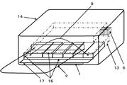
(4)交換用インクタンクの配置場所は本体のユーザーと対面するフロント側の下部位置であり、そこに、横一線にズラリと並べ置くことができる。ユーザーには極めて交換し易い。図3斜視図で示した従来機では、上蓋を開け、複合機であれば上部のスキャナーごと持ち上げるのであるが、それから覗き込むようにしてインクタンクを交換している。一方図8の本発明の配置では、前面のインクタンク収納部扉17を開け、インクタンク収納部取り出し口16から必要なインクタンク9を交換する。両者の扱い容易性は一目瞭然である。なお、本発明の持つ1つの欠点は、排紙トレイ2が補充用インクタンクの交換のための収納部取り出し口16および扉17の直上にあり、このままではインクタンク交換がやりにくいことである。これに対処するために、この排紙トレイを課題解決手段4記載のように、休止中あるいは停止中は記録装置本体内に自動的に引き込み格納させ、使用に当っては自動的に繰り出す機構を加えた。これにより、ユーザーは排紙トレイに邪魔されることなくインクタンク交換ができるようになった。なお次善の策として、従来機のように単に手動での取り外しやはね上げ、あるいは手動での格納と引き出しを行う、そのような機構を否定するものではない。
(4) The replacement ink tank is disposed at the lower position on the front side facing the user of the main body, and can be arranged side by side in a horizontal line there. It is very easy for the user to exchange. In the conventional machine shown in the perspective view of FIG. 3, the upper lid is opened, and in the case of a multifunction machine, the upper scanner is lifted together, but the ink tank is exchanged so as to look into it. On the other hand, in the arrangement of the present invention in FIG. 8, the ink tank housing door 17 on the front surface is opened, and the necessary ink tank 9 is replaced from the ink tank housing outlet 16. The ease of handling of both is obvious. One drawback of the present invention is that the paper discharge tray 2 is directly above the storage portion outlet 16 and the door 17 for replacement of the replenishment ink tank, so that it is difficult to replace the ink tank. In order to cope with this, as described in Problem Solving Means 4, this discharge tray is automatically retracted and stored in the main body of the recording apparatus during the pause or stop, and is automatically extended when used. added. As a result, the user can replace the ink tank without being disturbed by the paper discharge tray. As a suboptimal measure, it does not deny such a mechanism that performs manual removal and flip-up, or manual storage and withdrawal as in the conventional machine.
ビジネスユース機などで、さらにインク容量を増やしたければ、インクタンクの奥行きや幅を伸ばせばよい。具体的な構成を実施例で後述する。またインクの色数をさらに増やしたければ、その横幅を少し狭め奥行きを伸ばせばよい。このように設計の自由度が極めて高くなる。ただし、インクタンクの内側高さ2hは2pmm堅持が必須であり、これさえ守ればよいのである。
If you want to further increase the ink capacity on a business use machine, you can increase the depth and width of the ink tank. A specific configuration will be described later in Examples. To further increase the number of ink colors, the lateral width may be slightly narrowed to increase the depth. In this way, the degree of freedom in design becomes extremely high. However, it is essential that the inner height 2h of the ink tank is 2pmm, and it is only necessary to keep this.
これまでの説明に用いた図6、図7、図8の記録装置の基本構成と、図9、図10の関係図で示す自力汲み上げ条件に適う配置が本発明の典型的な形態である。具体的な構成を、黒、イエロー、マゼンダ、シアン、フォトマゼンダ、フォトシアンの6色を用いたコンシューマープロダクトジャンルのフォトプリンタで示す。
The basic configuration of the recording apparatus of FIGS. 6, 7, and 8 used in the above description and the arrangement suitable for the self-pumping conditions shown in the relational diagrams of FIGS. 9 and 10 are typical forms of the present invention. A specific configuration is shown by a consumer product genre photo printer using six colors of black, yellow, magenta, cyan, photo magenta, and photocyan.
オンキャリッジインクタンクの各色の内側寸法は0.9cmとした。それらの隔壁は0.1cm(これらのインクタンクは取り外して交換するものではないので、厚い容器壁や容器間の隙間などは不要である)、最外壁は0.2cm、合計幅は、0.9x6+0.1x5+0.2x2=6.3cmである。これを幅7cmのキャリッジに搭載した。本体幅は、紙幅21cmであるから、これに7x2cm+α(ギヤ等のメカニカル部品や外装の厚さや間隙などで略4cm)を加えて39cmとすることができる。従来機の6色オンキャリッジインクタンク搭載のキャリッジ幅は10cm近くかそれ以上であり、したがって本体幅は40cmを優に超えている。
The inner dimension of each color of the on-carriage ink tank was 0.9 cm. Their partition walls are 0.1 cm (there is no need to remove and replace these ink tanks, so there is no need for thick container walls or gaps between containers), the outermost wall is 0.2 cm, and the total width is 0.1 cm. 9x6 + 0.1x5 + 0.2x2 = 6.3 cm. This was mounted on a carriage having a width of 7 cm. Since the width of the main body is 21 cm, the width of the main body can be 39 cm by adding 7 × 2 cm + α (approximately 4 cm due to mechanical parts such as gears and the thickness and gap of the exterior). The carriage width of a conventional machine equipped with a six-color on-carriage ink tank is close to or more than 10 cm, and thus the main body width is well over 40 cm.
このインクタンクの奥行きは内寸法で5.0cmとした。これは特別短くはしていない。この場所の奥行き方向には十分な余裕があるからである。高さは外寸法1.4cm、内寸法1.0cmとした。単純計算では容量は4.5ccである。インク擾乱緩衝部材を設けているので、自由インク液量(緩衝部材に含まれる液量を除いた液量)は約3ccである。これは連続印刷で約100枚の印刷が可能な液量である。ここでは標準原稿1枚の印刷に0.03cc使うとした。このオンキャリッジインクタンクには常時インクが補給されており、わずかな補給タイムラグがあっても、そして連続印刷の場合でも、このくらいは印刷できる余裕がある量である、と言う意味である。ここで、連続印刷の場合にはその間に空吐出や吸引清掃などが無く、実際の印刷に消費されるインク量だけであるとして、標準原稿1枚の印刷に0.03cc使うとした。なお実際の記録装置としてのインク消費量は、前述のようにプリントヘッドの清掃目的の空吐出や吸引清掃などを行うので0.05ccで換算計算している。
The depth of this ink tank was 5.0 cm in internal dimensions. This is not particularly short. This is because there is a sufficient margin in the depth direction of this place. The height was 1.4 cm for the outer dimension and 1.0 cm for the inner dimension. In simple calculation, the capacity is 4.5 cc. Since the ink disturbance buffer member is provided, the free ink liquid amount (liquid amount excluding the liquid amount contained in the buffer member) is about 3 cc. This is the amount of liquid capable of printing about 100 sheets by continuous printing. Here, 0.03 cc is used for printing one standard original. This means that the on-carriage ink tank is always replenished with ink, and even if there is a slight replenishment time lag, and even in the case of continuous printing, this is an amount that can be printed. Here, in the case of continuous printing, it is assumed that 0.03 cc is used for printing one standard document, assuming that there is no idle ejection or suction cleaning in the meantime and only the amount of ink consumed for actual printing. Note that the ink consumption amount as an actual recording apparatus is calculated by conversion to 0.05 cc because empty ejection or suction cleaning for the purpose of cleaning the print head is performed as described above. *
交換用インクタンクは、その高さ位置と高さ幅さえ厳守すれば、自由度高く設計できる。作用・効果の項で例示したものが典型的な交換用インクタンクの形態である。再掲ではあるが、高さx横幅x奥行きが内径表示で2cmx4cmx8cmとすれば、約1,200枚強の印刷が可能である。奥行き長を、例えば14cmにすれば2,000枚強印刷可能となる(2x4x14=112cc→112/0.05=2,240枚)。
The replacement ink tank can be designed with a high degree of freedom as long as its height and width are strictly observed. What is exemplified in the section of action and effect is a typical form of a replacement ink tank. As shown again, if the height x width x depth is 2 cm x 4 cm x 8 cm in terms of inner diameter, printing of about 1,200 sheets or more is possible. If the depth length is set to 14 cm, for example, it is possible to print over 2,000 sheets (2 × 4 × 14 = 112 cc → 112 / 0.05 = 2,240 sheets).
オンキャリッジインクタンクの背丈が低いから、このことから得られるスペースがインクタンクの格好の置き場所となったのである。しかも装置本体の横幅一杯に使える。奥行き方向にも、大きなスペースがある。タンクの高さが好むと好まざるにかかわらず、とにかく低い。これがかえってこのような設計の自由度、あるいは拡張性をもたらしてくれるのである。そのためにも記述の考究に基づくH=Pと好ましくはh=pを厳密に適用することが肝心であり、これさえ厳守すれば安心して自由な設計ができるのである。
Since the height of the on-carriage ink tank is low, the space obtained from this has become a suitable place for the ink tank. Moreover, it can be used to the full width of the device. There is also a large space in the depth direction. Regardless of whether you prefer the height of the tank, it is low anyway. This in turn brings about such design freedom or extensibility. For this purpose, it is important to strictly apply H = P and preferably h = p based on the study of the description. If even this is strictly observed, a free design can be performed with peace of mind.
本発明の構成では、ユーザーによるインクタンクの交換は、必然的に排紙トレイ2の下側のインクタンク収納部扉17を開けインクタンク収納部取り出し口16からの交換となる。記録装置の前面での操作であるのでやり易いのではあるが、そのたびにインクタンク収納部取り出し口16の上方にある排紙トレイ2を取り除いて、あるいは記録装置本体内に押し込んでインクタンク交換をしなければならない。インクタンク交換の前面での操作のやり易さを活かすためにも、インクタンク交換時には排紙トレイが自動的に記録装置本体内に引き込まれていてほしい。またそのほうが記録装置不使用時、使っていない排紙トレイが出っ張っていて邪魔になることは無いし、見た目もすっきりする。
In the configuration of the present invention, the replacement of the ink tank by the user is inevitably performed by opening the ink tank storage section door 17 on the lower side of the paper discharge tray 2 and from the ink tank storage section outlet 16. Although it is easy to do because it is an operation on the front side of the recording apparatus, the ink tank replacement is performed by removing the paper discharge tray 2 above the ink tank storage section takeout port 16 or pushing it into the recording apparatus main body each time. Have to do. In order to take advantage of the ease of operation at the front of the ink tank replacement, the paper discharge tray should be automatically pulled into the recording device body when the ink tank is replaced. In addition, when the recording apparatus is not used, the unused paper discharge tray protrudes and does not get in the way, and the appearance is also clear.
上記目的を果たすために自動伸長型排紙トレイを具備する記録装置18を考案した。図14~図19を用いて説明する。番号20が自動伸長型排紙トレイである。この設計では3段の伸長でA4紙をカバーする寸法とした。自動伸長型排紙トレイ20は鋼製丸棒でなる3個の伸長型排紙トレイ21,22,23から構成される。それぞれの左右両端は丸棒を縦方向に長く押しつぶし、その下部に直線ギヤ24を刻み設けた。記録装置本体の内部最前面箇所に、この直線ギヤ24に対応して排紙トレイ駆動ギヤ25を置く。伸長型排紙トレイの動きの説明図を図14の下部の20-0,20-1,20-2,20-3に取りだして示した。出発点は20-0で、駆動ギヤ25の回転により、22と23を乗せた第一段の伸長型排紙トレイ21を送り出す。図14の20-1である。21の終端が駆動ギヤ25を外れたところで、駆動ギヤ25は第二段として伸長型排紙トレイ23を乗せた22に系合しこれを送り出す。図14の20-2である。次いで同様に第三段として伸長型排紙トレイ23に系合しこれを送り出す。図14の20-3である。
In order to achieve the above purpose, a recording device 18 having an automatic extension type paper discharge tray has been devised. This will be described with reference to FIGS. Reference numeral 20 denotes an automatic extension type paper discharge tray. In this design, the A4 paper is covered by three stages of extension. The automatic extension type paper discharge tray 20 is composed of three extension type paper discharge trays 21, 22 and 23 made of steel round bars. At both left and right ends, a round bar was squeezed long in the vertical direction, and a linear gear 24 was cut in the lower part. A paper discharge tray drive gear 25 is placed in correspondence with the linear gear 24 at the forefront portion inside the recording apparatus main body. Explanatory diagrams of the movement of the extension type paper discharge tray are shown at 20-0, 20-1, 20-2 and 20-3 at the bottom of FIG. The starting point is 20-0, and the first-stage extension type paper discharge tray 21 on which 22 and 23 are placed is sent out by the rotation of the drive gear 25. This is 20-1 in FIG. When the terminal 21 is disengaged from the drive gear 25, the drive gear 25 is engaged with the extension 22 of the extension type paper discharge tray 23 as a second stage and sends it out. This is 20-2 in FIG. Next, in the same manner, as the third stage, it is combined with the extension type paper discharge tray 23 and sent out. This is 20-3 in FIG.
図14の20-0、自動伸長型排紙トレイ20が収納されている出発点の状態であるが、これに対応する平面図を図15に示した。この状態で記録装置は休止あるいはシャットダウンしており、記録装置からは排紙トレイは出ていない。そして、ユーザーは排紙トレイに邪魔されることなくインクタンクの交換ができる。図16は記録装置再稼働に当り、先ず第一段の伸長型排紙トレイ21を送り出した所である。図14の20-1の状態の平面図である。図17は図14の20-2に相当する平面図であり、トレイ21を乗せた第二段の伸長型排紙トレイ22を送り出した所である。そして図18は図14の20-3に相当する平面図であり、トレイ21と22を乗せた第三段の伸長型排紙トレイ23を送り出した所である。
FIG. 15 is a plan view corresponding to 20-0 in FIG. 14, which is a starting point where the automatic extension type paper discharge tray 20 is accommodated. In this state, the recording apparatus is paused or shut down, and the paper discharge tray is not ejected from the recording apparatus. The user can replace the ink tank without being disturbed by the paper discharge tray. FIG. 16 shows a state where the first-stage extension type paper discharge tray 21 is sent out when the recording apparatus is restarted. It is a top view of the state of 20-1 of FIG. FIG. 17 is a plan view corresponding to 20-2 of FIG. 14, where the second-stage extension type paper discharge tray 22 on which the tray 21 is placed is sent out. FIG. 18 is a plan view corresponding to 20-3 in FIG. 14, where the third-stage extension type paper discharge tray 23 on which the trays 21 and 22 are placed is sent out.
図19に伸長型排紙トレイ3段を全て伸長させた様子を横断面図で示した。図示していないが、これらの一連の動きを制御する装置はもちろん必要である。一般的な設計事項の一つであり特別なものではない。排紙トレイ上の印刷物の有無を検知して、無ければ自動的に駆動ギヤ25を逆転させて、上記と逆の順番で伸長型排紙トレイを記録装置本体内に収納するのも一案である。当然、ユーザーによるか自動かは問わず、シャットダウンに入る前にも駆動ギヤ25を逆転させてトレイは本体内に収納される。
FIG. 19 is a cross-sectional view showing a state in which all three stages of the extension type paper discharge tray are extended. Although not shown, of course, an apparatus for controlling these series of movements is necessary. It is one of the general design items and is not special. It is also possible to detect the presence or absence of printed matter on the paper discharge tray, and automatically reverse the drive gear 25 if there is not, and store the extension type paper discharge tray in the recording apparatus main body in the reverse order. is there. Naturally, regardless of whether it is by the user or automatic, the drive gear 25 is reversed before the shutdown is entered, and the tray is stored in the main body.
ビジネスユース向きのプリタであるならば、1万枚印刷できる交換用インクタンクも容易に設計可能である。例えば、黒用インクタンク横幅12cm、奥行き22cmとすれば、上記同様の表現で、インクタンク容量は2cmx12cmx22cmで528cc、すなわち印刷可能枚数は10,560枚である。カラー用2色を幅7cm奥行きは黒と同じとすれば、2cmx7cmx22cm=308ccすなわち印刷可能枚数は6,160枚/1色である。残りの1色は、プリントヘッドの回復機構を避け奥行き長を18cmとし横幅を9cmとした。容積は2cmx9cmx18cm=324cc、すなわち印刷可能枚数は6,480枚である。4色タンク全体の横幅は、12cm+7cmx2+9=35cm(+容器壁厚と間隔で合計略37cm)である。図12および図13に、この大型交換用インクタンク搭載の記録装置15を示す。図13では見やすいように交換用インクタンク群9とその収納可能空間13を中心に表示し、他のキャリッジ部分やインク導管や紙送り機構は省略してある。
If it is a printer suitable for business use, a replacement ink tank capable of printing 10,000 sheets can be easily designed. For example, assuming that the black ink tank has a lateral width of 12 cm and a depth of 22 cm, the ink tank capacity is 2 cm × 12 cm × 22 cm and is 528 cc, that is, the printable number is 10,560. If the two colors for color are 7 cm wide and the same depth as black, 2 cm × 7 cm × 22 cm = 308 cc, that is, the number of printable sheets is 6,160 / color. For the remaining one color, the depth length was 18 cm and the width was 9 cm, avoiding the printhead recovery mechanism. The volume is 2 cm × 9 cm × 18 cm = 324 cc, that is, the number of printable sheets is 6,480. The overall width of the four-color tank is 12 cm + 7 cm × 2 + 9 = 35 cm (+ total container wall thickness and spacing is approximately 37 cm). FIG. 12 and FIG. 13 show the recording apparatus 15 equipped with this large replacement ink tank. In FIG. 13, for the sake of easy understanding, the replacement ink tank group 9 and its accommodating space 13 are displayed in the center, and other carriage parts, ink conduits, and paper feeding mechanisms are omitted.
インク擾乱緩衝機構の他の実施例を図11に示す。迷路62で構成されるインク擾乱緩機構を具備している。他の番号は、図9および図10と同様である。
FIG. 11 shows another embodiment of the ink disturbance buffer mechanism. An ink disturbance relaxation mechanism including a maze 62 is provided. Other numbers are the same as those in FIGS. 9 and 10.
本発明実施例の自動伸長型排紙トレイを具備する記録装置18,19の伸長/繰り出しおよび引き込み/格納のメカニズムは、他分野では多く使われているものであり、特別のものではない。他の類似の自動メカニズムの記録装置への援用も適宜使われてしかるべきものである。これまでのインクジェット方式の記録装置において、このような自動伸長/格納型排紙トレイが存在したかどうかは定かではないが、本発明の「インクタンク取り出し口の直ぐ上に排紙トレイがある構成」においては、必然ではないものの、極めてユーザーフレンドリーな設計的配慮である。
The extending / drawing and retracting / storing mechanisms of the recording devices 18 and 19 having the automatic extension type paper discharge tray according to the embodiment of the present invention are widely used in other fields and are not special. Incorporation of other similar automatic mechanisms into recording devices should be used as appropriate. Although it is not certain whether or not such an automatic extension / storage type paper discharge tray exists in the ink jet type recording apparatus so far, the “configuration with the paper discharge tray immediately above the ink tank outlet” of the present invention "Is a design consideration that is very user-friendly but not necessary.
本発明は以上の実施形態に限定されることなく、公知のインクジェット方式記録装置に提案されている様々な要素技術を設計の目的に応じて援用することは、交換用インクタンクの高さ位置をH=Pとすることと、交換用インクタンクの高さ幅2hを2p以内とすること、この2点を必要十分な前提条件として厳密に適用しさえすれば、種々の実施形態を可能とするものである。
The present invention is not limited to the above embodiment, and various elemental technologies proposed for known ink jet recording apparatuses can be used according to the purpose of design to determine the height position of the replacement ink tank. Various embodiments can be realized as long as H = P, the height width 2h of the replacement ink tank is within 2p, and these two points are strictly applied as necessary and sufficient preconditions. Is.
本発明をコンシューマープロダクツとしてのインクジェト方式記録装置を中心に説明し、ビジネスユースのプリンタへの適用も紹介してきた。コストをかけても良い、大判プリンタや、プロ仕様の写真用プリンタ、あるいは産業用のプリンタにも適用できる。また、さらにはポータブルプリンタですら、設計の狙いによれば使ってみることも有意な効果をもたらしてくれることもあろう。
The present invention has been mainly described for an inkjet recording apparatus as a consumer product, and its application to a business use printer has also been introduced. It can also be applied to large format printers, professional photographic printers, or industrial printers that may be costly. And even portable printers can have a significant effect if you use them, depending on your design goals.
1 紙カセット
2 排紙トレイ
3 紙搬送路
4 プリントヘッド
5 従来型オンキャリッジインクタンク
6 小型オンキャリッジインクタンク
7 インク導管
8 横側配置オフキャリッジインクタンク
10 従来機外形の概念図
12 プリントヘッドの回復機構
13 収納可能空間
14 本案記録装置の外形概念図
15 大型交換用インクタンク搭載の記録装置
16 インクタンク収納部からのインクタンク取り出し口
17 インクタンク収納部扉
18 自動伸長型排紙トレイ装着記録装置
20 伸長型排紙トレイ
21 第一伸長型排紙トレイ
22 第二伸長型排紙トレイ
23 第三伸長型排紙トレイ
24 伸長型排紙トレイの直線ギヤ
25 伸長型排紙トレイ駆動ギヤ
31 プリントヘッド直下の紙搬送路
32 紙ピックアップローラー
60 インク室
61 多孔質材インク緩衝機構
62 迷路型インク緩衝機構
65 気泡
66 気体放出機構
71 プリンタ本体の連結機構
72 ニードル
90 ハードインク容器
91 インク袋
92 空気を取り入れる孔
93 連結用シール部材 DESCRIPTION OFSYMBOLS 1 Paper cassette 2 Paper discharge tray 3 Paper conveyance path 4 Print head 5 Conventional on-carriage ink tank 6 Small on-carriage ink tank 7 Ink conduit
8 Horizontally arranged off-carriage ink tank 10 Conceptual diagram of external shape of conventional machine 12 Recovery mechanism of print head 13 Storage space 14 Conceptual diagram of external shape of proposed recording device 15 Recording device equipped with large replacement ink tank 16 From ink tank storage unit Ink tank outlet 17 Ink tank storage door 18 Automatic extension type discharge tray mounting recording device 20 Extension type discharge tray 21 First extension type discharge tray 22 Second extension type discharge tray 23 Third extension type discharge tray 24 Elongation Type Discharge Tray Linear Gear 25 Elongation Type Ejection Tray Drive Gear 31 Paper Transport Path Directly Under Print Head 32 Paper Pickup Roller 60 Ink Chamber 61 Porous Material Ink Buffer Mechanism 62 Maze Type Ink Buffer Mechanism 65 Bubble 66 Gas Release Mechanism 71 Printer body coupling mechanism 72 Needle 90 Hard ink container 91 Ink bag 92 Hole for taking in air 93 Sealing member for connection
2 排紙トレイ
3 紙搬送路
4 プリントヘッド
5 従来型オンキャリッジインクタンク
6 小型オンキャリッジインクタンク
7 インク導管
8 横側配置オフキャリッジインクタンク
10 従来機外形の概念図
12 プリントヘッドの回復機構
13 収納可能空間
14 本案記録装置の外形概念図
15 大型交換用インクタンク搭載の記録装置
16 インクタンク収納部からのインクタンク取り出し口
17 インクタンク収納部扉
18 自動伸長型排紙トレイ装着記録装置
20 伸長型排紙トレイ
21 第一伸長型排紙トレイ
22 第二伸長型排紙トレイ
23 第三伸長型排紙トレイ
24 伸長型排紙トレイの直線ギヤ
25 伸長型排紙トレイ駆動ギヤ
31 プリントヘッド直下の紙搬送路
32 紙ピックアップローラー
60 インク室
61 多孔質材インク緩衝機構
62 迷路型インク緩衝機構
65 気泡
66 気体放出機構
71 プリンタ本体の連結機構
72 ニードル
90 ハードインク容器
91 インク袋
92 空気を取り入れる孔
93 連結用シール部材 DESCRIPTION OF
8 Horizontally arranged off-
Claims (4)
- インクジェット方式記録装置において、少なくとも、プリントヘッドと一体化したオンキャリッジインクタンクと、交換可能な補充用インクタンクと、該補充用インクタンクからインクをオンキャリッジインクタンクに導く可撓性インク導管とから成るインク供給系であること、該補充用インクタンクをプリントヘッドの下方に配置し、その高さ方向の中心位置をプリントヘッドから下方にHmmその高さ方向の幅を±hmmすなわち2hmmとするとき、プリントヘッドに連なる液室の負圧変動許容値が-(P±p)mmH2Oであるならば、h≦pかつ|P-H|≦pとすることにより該許容負圧のみで補充用インクタンクからオンキャリッジインクタンクにインクを吸い上げることを特徴とするインクジェット方式記録装置。 In an ink jet recording apparatus, at least an on-carriage ink tank integrated with a print head, a replaceable refill ink tank, and a flexible ink conduit for guiding ink from the refill ink tank to the on-carriage ink tank When the replenishment ink tank is disposed below the print head and the center position in the height direction is Hmm downward from the print head and the width in the height direction is ± hmm, that is, 2 hmm. If the permissible negative pressure fluctuation value of the liquid chamber connected to the print head is − (P ± p) mmH 2 O, replenishing ink with only the permissible negative pressure by setting h ≦ p and | PH | ≦ p. An ink jet recording apparatus that sucks up ink from a tank into an on-carriage ink tank.
- 請求項1において、特に、h=pかつH=Pであることを特徴とするインクジェット記録装置。 2. An ink jet recording apparatus according to claim 1, wherein h = p and H = P.
- 請求項1および2において、補充用インクタンクの配置条件を、プリントヘッド下方であってh≦pかつ|P-H|≦pあるいは特にh=pかつH=Pであるという条件に加え、記録装置本体の横方向および奥行き方向において、プリントヘッドの回復機構と紙送り機構を避けた全域に亘る空間内の任意位置とすることを特徴とするインクジェット記録装置。 3. The recording medium according to claim 1, wherein the replenishment ink tank is disposed under the condition that h ≦ p and | PH | ≦ p or particularly h = p and H = P below the print head. An ink jet recording apparatus having an arbitrary position in a space over a whole area avoiding a recovery mechanism and a paper feed mechanism of a print head in a lateral direction and a depth direction of the apparatus main body.
- 請求項1、2および3において、交換可能な補充用インクタンクの配置空間の直上に位置する排紙トレイが、記録装置休止中あるいは停止中は記録装置本体内に自動的に引き込まれ格納され、記録装置作動中は自動的に本体内の格納位置から伸長あるいは繰り出されていることを特徴とするインクジェット記録装置。 In Claims 1, 2, and 3, the paper discharge tray positioned immediately above the space where the replaceable replenishment ink tank is disposed is automatically drawn into and stored in the main body of the recording apparatus when the recording apparatus is stopped or stopped. An ink jet recording apparatus which is automatically extended or extended from a storage position in the main body during operation of the recording apparatus.
Applications Claiming Priority (2)
| Application Number | Priority Date | Filing Date | Title |
|---|---|---|---|
| JP2012104996A JP2013230651A (en) | 2012-05-01 | 2012-05-01 | Inkjet recording device |
| JP2012-104996 | 2012-05-01 |
Publications (1)
| Publication Number | Publication Date |
|---|---|
| WO2013165012A1 true WO2013165012A1 (en) | 2013-11-07 |
Family
ID=49514410
Family Applications (1)
| Application Number | Title | Priority Date | Filing Date |
|---|---|---|---|
| PCT/JP2013/062694 WO2013165012A1 (en) | 2012-05-01 | 2013-05-01 | Inkjet recording device |
Country Status (2)
| Country | Link |
|---|---|
| JP (1) | JP2013230651A (en) |
| WO (1) | WO2013165012A1 (en) |
Cited By (1)
| Publication number | Priority date | Publication date | Assignee | Title |
|---|---|---|---|---|
| WO2019147238A1 (en) * | 2018-01-25 | 2019-08-01 | Hewlett-Packard Development Company, L.P. | Tanks for print cartridge |
Families Citing this family (2)
| Publication number | Priority date | Publication date | Assignee | Title |
|---|---|---|---|---|
| US10632762B2 (en) | 2017-02-02 | 2020-04-28 | Ricoh Company, Ltd. | Heating apparatus and image forming system |
| JP7091753B2 (en) | 2017-10-20 | 2022-06-28 | セイコーエプソン株式会社 | Liquid sprayer |
Citations (4)
| Publication number | Priority date | Publication date | Assignee | Title |
|---|---|---|---|---|
| JP2002144601A (en) * | 2000-11-16 | 2002-05-22 | Canon Inc | Sub-ink tank and ink jet recorder |
| JP2003112435A (en) * | 2001-08-01 | 2003-04-15 | Canon Inc | Liquid supply device and liquid discharge recorder |
| JP2006110900A (en) * | 2004-10-15 | 2006-04-27 | Canon Inc | Ink-jet recorder |
| JP2006327802A (en) * | 2005-05-30 | 2006-12-07 | Canon Inc | Ink jet recording device |
Family Cites Families (7)
| Publication number | Priority date | Publication date | Assignee | Title |
|---|---|---|---|---|
| JP3818194B2 (en) * | 2002-03-28 | 2006-09-06 | ブラザー工業株式会社 | Recording device |
| JP2003334967A (en) * | 2002-05-22 | 2003-11-25 | Canon Inc | Liquid supplying unit |
| JP3750808B2 (en) * | 2002-07-26 | 2006-03-01 | ブラザー工業株式会社 | Inkjet printer |
| JP2004174815A (en) * | 2002-11-26 | 2004-06-24 | Canon Inc | Constant negative pressure generator of ink head |
| JP4782602B2 (en) * | 2006-03-31 | 2011-09-28 | 富士フイルム株式会社 | Inkjet recording apparatus and inkjet recording method |
| JP4806616B2 (en) * | 2006-09-29 | 2011-11-02 | 富士フイルム株式会社 | Ink cartridge and ink jet recording apparatus |
| JP5471599B2 (en) * | 2010-03-02 | 2014-04-16 | 株式会社リコー | Image forming apparatus |
-
2012
- 2012-05-01 JP JP2012104996A patent/JP2013230651A/en active Pending
-
2013
- 2013-05-01 WO PCT/JP2013/062694 patent/WO2013165012A1/en active Application Filing
Patent Citations (4)
| Publication number | Priority date | Publication date | Assignee | Title |
|---|---|---|---|---|
| JP2002144601A (en) * | 2000-11-16 | 2002-05-22 | Canon Inc | Sub-ink tank and ink jet recorder |
| JP2003112435A (en) * | 2001-08-01 | 2003-04-15 | Canon Inc | Liquid supply device and liquid discharge recorder |
| JP2006110900A (en) * | 2004-10-15 | 2006-04-27 | Canon Inc | Ink-jet recorder |
| JP2006327802A (en) * | 2005-05-30 | 2006-12-07 | Canon Inc | Ink jet recording device |
Cited By (3)
| Publication number | Priority date | Publication date | Assignee | Title |
|---|---|---|---|---|
| WO2019147238A1 (en) * | 2018-01-25 | 2019-08-01 | Hewlett-Packard Development Company, L.P. | Tanks for print cartridge |
| CN111565934A (en) * | 2018-01-25 | 2020-08-21 | 惠普发展公司,有限责任合伙企业 | Cartridge for print cartridge |
| US11298944B2 (en) | 2018-01-25 | 2022-04-12 | Hewlett-Packard Development Company, L.P. | Tanks for print cartridge |
Also Published As
| Publication number | Publication date |
|---|---|
| JP2013230651A (en) | 2013-11-14 |
Similar Documents
| Publication | Publication Date | Title |
|---|---|---|
| CN109927414B (en) | Printing apparatus and liquid storage container | |
| JP2013184424A (en) | Inkjet printing apparatus | |
| JP6075097B2 (en) | Liquid container, liquid supply system | |
| KR20050031385A (en) | Liquid supplying system and apparatus incorporating the same | |
| JP7327976B2 (en) | Inkjet recording device and ink tank | |
| CN111791585B (en) | Ink jet printing apparatus and ink tank | |
| WO2013165012A1 (en) | Inkjet recording device | |
| WO2013147167A2 (en) | Ink-jet recording device | |
| TW422788B (en) | Ink containment device and method of construcing the same | |
| JP6119338B2 (en) | Image recording device | |
| JP2019043019A (en) | Ink tank and inkjet recording device | |
| US10457064B2 (en) | Liquid consumption apparatus having cartridge, cartridge attachment section provided with tank, and consuming device | |
| JP4608730B2 (en) | Inkjet printer and head cartridge thereof | |
| JP7035647B2 (en) | system | |
| JP6969196B2 (en) | Liquid consuming device | |
| JP4557410B2 (en) | Sub ink tank, ink jet head cartridge, and ink jet recording apparatus | |
| JP6508569B2 (en) | Inkjet printer | |
| CN211808467U (en) | Ink-injection cylinder, ink tank and ink-jet printer | |
| JP6666052B2 (en) | Recording device | |
| CN211808460U (en) | Ink-injection cylinder, ink tank and ink-jet printer | |
| JP5842604B2 (en) | Ink supply apparatus and image recording apparatus | |
| JP6296377B2 (en) | Liquid cartridge | |
| JP2000218815A (en) | Ink jet recording apparatus | |
| JP2022071109A (en) | system | |
| JP2021014126A (en) | Recording device |
Legal Events
| Date | Code | Title | Description |
|---|---|---|---|
| 121 | Ep: the epo has been informed by wipo that ep was designated in this application |
Ref document number: 13784437 Country of ref document: EP Kind code of ref document: A1 |
|
| DPE2 | Request for preliminary examination filed before expiration of 19th month from priority date (pct application filed from 20040101) | ||
| NENP | Non-entry into the national phase |
Ref country code: DE |
|
| 122 | Ep: pct application non-entry in european phase |
Ref document number: 13784437 Country of ref document: EP Kind code of ref document: A1 |