WO2013161825A1 - マルチコア光ファイバ、マルチコア光ファイバケーブル、および、マルチコア光ファイバ伝送システム - Google Patents
マルチコア光ファイバ、マルチコア光ファイバケーブル、および、マルチコア光ファイバ伝送システム Download PDFInfo
- Publication number
- WO2013161825A1 WO2013161825A1 PCT/JP2013/061940 JP2013061940W WO2013161825A1 WO 2013161825 A1 WO2013161825 A1 WO 2013161825A1 JP 2013061940 W JP2013061940 W JP 2013061940W WO 2013161825 A1 WO2013161825 A1 WO 2013161825A1
- Authority
- WO
- WIPO (PCT)
- Prior art keywords
- optical fiber
- cores
- core optical
- core
- less
- Prior art date
Links
- 239000013307 optical fiber Substances 0.000 title claims abstract description 168
- 230000005540 biological transmission Effects 0.000 title claims description 43
- 238000004364 calculation method Methods 0.000 claims abstract description 43
- 239000000835 fiber Substances 0.000 claims abstract description 36
- 238000000034 method Methods 0.000 claims abstract description 16
- 238000005452 bending Methods 0.000 claims description 29
- 238000005516 engineering process Methods 0.000 claims description 11
- 238000005253 cladding Methods 0.000 claims description 4
- 230000008878 coupling Effects 0.000 description 6
- 238000010168 coupling process Methods 0.000 description 6
- 238000005859 coupling reaction Methods 0.000 description 6
- 238000004804 winding Methods 0.000 description 5
- 238000005070 sampling Methods 0.000 description 3
- 238000012935 Averaging Methods 0.000 description 2
- 239000006185 dispersion Substances 0.000 description 2
- 230000000694 effects Effects 0.000 description 2
- 239000011521 glass Substances 0.000 description 2
- 230000010287 polarization Effects 0.000 description 2
- 230000004044 response Effects 0.000 description 2
- 238000000926 separation method Methods 0.000 description 2
- 108010076504 Protein Sorting Signals Proteins 0.000 description 1
- 230000015572 biosynthetic process Effects 0.000 description 1
- 230000008859 change Effects 0.000 description 1
- 239000011248 coating agent Substances 0.000 description 1
- 238000000576 coating method Methods 0.000 description 1
- 230000007423 decrease Effects 0.000 description 1
- 238000010586 diagram Methods 0.000 description 1
- 239000011159 matrix material Substances 0.000 description 1
- 230000003287 optical effect Effects 0.000 description 1
- 230000009467 reduction Effects 0.000 description 1
- 239000011347 resin Substances 0.000 description 1
- 229920005989 resin Polymers 0.000 description 1
- 238000004088 simulation Methods 0.000 description 1
- 230000007704 transition Effects 0.000 description 1
Images


Classifications
-
- G—PHYSICS
- G02—OPTICS
- G02B—OPTICAL ELEMENTS, SYSTEMS OR APPARATUS
- G02B6/00—Light guides; Structural details of arrangements comprising light guides and other optical elements, e.g. couplings
- G02B6/02—Optical fibres with cladding with or without a coating
- G02B6/02042—Multicore optical fibres
-
- G—PHYSICS
- G02—OPTICS
- G02B—OPTICAL ELEMENTS, SYSTEMS OR APPARATUS
- G02B6/00—Light guides; Structural details of arrangements comprising light guides and other optical elements, e.g. couplings
- G02B6/44—Mechanical structures for providing tensile strength and external protection for fibres, e.g. optical transmission cables
- G02B6/4401—Optical cables
- G02B6/441—Optical cables built up from sub-bundles
- G02B6/4413—Helical structure
-
- G—PHYSICS
- G02—OPTICS
- G02B—OPTICAL ELEMENTS, SYSTEMS OR APPARATUS
- G02B6/00—Light guides; Structural details of arrangements comprising light guides and other optical elements, e.g. couplings
- G02B6/44—Mechanical structures for providing tensile strength and external protection for fibres, e.g. optical transmission cables
- G02B6/4401—Optical cables
Definitions
- the present invention relates to a multi-core optical fiber, a multi-core optical fiber cable, and a multi-core optical fiber transmission system.
- a technique of twisting the core is used to reduce polarization mode dispersion (PMD) in an optical fiber that confines and transmits light inside the core extending along a predetermined axis.
- PMD polarization mode dispersion
- Patent Document 1 when a single-core optical fiber is drawn, the glass in a molten state is twisted (spinned) so that the influence of residual stress that is non-circular or non-circular is in a specific direction. A configuration is shown that randomizes without bias and reduces PMD due to the fiber itself.
- Patent Document 2 discloses a configuration in which a single core optical fiber is twisted after glass is solidified to reduce PMD caused by the outside of the fiber such as fiber bending and lateral pressure.
- Non-Patent Document 1 in a non-coupled multicore optical fiber in which crosstalk between a plurality of cores is reduced to suppress interference between signals, the magnitude (statistical average value) of crosstalk is at least an optical fiber. It has been shown that it does not depend on the twisting. Further, in Non-Patent Document 2, when the twist rate per unit length is precisely controlled and a constant short pitch of about 100 revolutions / m is set, crosstalk between cores in an uncoupled multicore optical fiber is reduced. Simulation results indicating the possibility of significant reduction are shown.
- Non-Patent Document 3 signals are transmitted using a coupled multi-core optical fiber (multi-core optical fiber having high crosstalk between cores), and signals of each core mixed by crosstalk are separated by MIMO technology. Decoding techniques are described.
- the present invention has been made to solve the above-described problems, and provides a multi-core optical fiber, a multi-core optical fiber cable, and a multi-core optical fiber transmission system that enable calculation using the MIMO technology effectively.
- the purpose is to do.
- the multi-core optical fiber according to the present embodiment extends along a predetermined axis (an axis extending along the longitudinal direction of the multi-core optical fiber) and is disposed on a cross section perpendicular to the predetermined axis.
- the plurality of cores and a clad region that integrally surrounds each of the plurality of cores are provided, and the plurality of cores are spirally rotated about a predetermined axis.
- the multi-core optical fiber according to the first aspect is defined by a value obtained by averaging the absolute values of the angles at which a plurality of cores rotate per unit length of the multi-core optical fiber along the longitudinal direction of the multi-core optical fiber.
- the bending radius in use defined by the bending radius when using an optical fiber is R (m)
- the speed of light in vacuum is c (m / s)
- the circumference is ⁇
- the first condition is defined by the following expression (1) being 7.91 ⁇ 10 ⁇ 12 (s / m 1/2 ) or less.
- the second condition is that the following equation (2) is 7.91 ⁇ 10 ⁇ 12 ⁇ 1 / R bobbin (s / m 1/2 ) or less when wound on a bobbin having a radius R bobbin (m). It is prescribed by that.
- the third condition is defined by the shortest distance ⁇ being about 25 ⁇ 10 ⁇ 6 m or less and the average twist rate ⁇ being about 4.72 rad / m or more.
- the fourth condition is defined by the shortest distance ⁇ being about 25 ⁇ 10 ⁇ 6 m or less.
- the fifth condition is defined by the fact that the crosstalk between adjacent cores is ⁇ 15 dB or more.
- the above formula (2) is 7.91 ⁇ 10 ⁇ 12 ⁇ 0.2 / R bobbin when wound on a bobbin having a radius R bobbin (m). It is preferably (s / m 1/2 ) or less.
- the first condition is that the formula (1) is 1.58 ⁇ 10 ⁇ 13 (s / m 1/2 ) or less, and when the second condition is wound around a bobbin having a radius R bobbin (m), the above equation (2) is 1.58 ⁇ 10 ⁇ 13 ⁇ 1.
- the above expression (2) is 1.58 ⁇ It is preferably 10 ⁇ 13 ⁇ 0.2 / R bobbin (s / m 1/2 ) or less.
- the bending radius R in use is preferably 1 m or more.
- the bending radius R in use is preferably 0.2 m or more.
- the multi-core optical fiber has a plurality of cores at equal intervals on the circumference of the same circle in cross section. You may provide the at least 1 core group comprised by the some core arrange
- the cores belonging to the core group have the same structure, and the crosstalk between adjacent cores among the cores belonging to the core group is preferably ⁇ 15 dB or more.
- a plurality of core groups may be configured by the above-described plurality of cores, and in such a configuration in which the plurality of core groups are arranged, Each core group is arranged in a sufficiently separated state so that the talk becomes -15 dB or less.
- all The cores belonging to the core group are preferably arranged on any one of a plurality of concentric circles.
- a plurality of cores extending along a predetermined axis and arranged on a cross section perpendicular to the predetermined axis are integrated with each of the plurality of cores.
- a multi-core optical fiber having a clad region surrounded by the core is incorporated, and the plurality of cores rotate around the predetermined axis.
- the multi-core optical fiber cable according to the ninth aspect is defined by an average value of angles of rotation of a plurality of cores per unit length of the multi-core optical fiber along the longitudinal direction of the multi-core optical fiber.
- the average twist rate is ⁇ (rad / m)
- the shortest distance between the centers of each of the cores is ⁇ (m)
- the group refractive index for the fundamental mode in each of the cores is ng
- the multicore light When the in-use bend radius defined by the bend radius in use of the fiber is R (m), the speed of light in vacuum is c (m / s), and the circumference is ⁇ , the following equation (3)
- the multi-core optical fiber is built-in while maintaining a state in which is less than 7.91 ⁇ 10 ⁇ 12 (s / m 1/2 ).
- the multi-core optical fiber maintains the state in which the expression (3) is 1.58 ⁇ 10 ⁇ 13 (s / m 1/2 ) or less. Is preferably incorporated.
- the multicore optical fiber in the multicore optical fiber cable, has an average value of a bending radius along the longitudinal direction. It is preferably built in so as to be 0.2 m or more.
- the shortest distance ⁇ is preferably 25 ⁇ 10 ⁇ 6 m or less.
- the crosstalk between adjacent cores among a plurality of cores is ⁇ 15 dB or more.
- the multi-core optical fiber transmission system includes, as a fourteenth aspect, a plurality of cores extending along a predetermined axis and arranged on a cross section perpendicular to the predetermined axis, and a plurality of cores.
- a multi-core optical fiber having an integrally surrounded cladding region is used as a transmission line.
- the absolute value of the angle at which a plurality of cores rotate per unit length of the multi-core optical fiber is defined as an average value along the longitudinal direction of the multi-core optical fiber.
- the average torsion rate to be performed is ⁇ (rad / m), the shortest distance between the centers of the plurality of cores is ⁇ (m), the group refractive index for the ground mode in each of the plurality of cores is ng, and multicore
- the longitudinal average value defined by the average value of the bending radii along the longitudinal direction of the optical fiber is R (m)
- the speed of light in vacuum is c (m / s)
- the circumference is ⁇
- the tap number N tap when performing decoding calculation by the MIMO technique satisfies the relationship defined by the following equation (4). Is set to
- the shortest distance ⁇ is 25 ⁇ 10 ⁇ 6 m or less.
- the multi-core optical fiber according to at least one of the first to eighth aspects may be applied as a transmission line.
- MIMO MIMO It is preferable that the tap number N tap when performing the decoding calculation by the technique is set so as to satisfy the relationship defined by the following formula (5).
- the multi-core optical fiber cable according to at least one of the ninth to thirteenth aspects may be applied as a transmission line.
- the MIMO technology is used. It is preferable that the tap number N tap when performing the decoding calculation is set so as to satisfy the relationship defined by the following equation (6).
- the crosstalk between adjacent cores among a plurality of cores is ⁇ 15 dB or more.
- a multi-core optical fiber a multi-core optical fiber cable, and a multi-core optical fiber transmission system that enable calculation using the MIMO technique effectively.
- the multi-core optical fiber according to the present embodiment will be described.
- the MIMO technique a technique for compensating for crosstalk between spatial modes and performing spatial multiplexing (core multiplexing / mode multiplexing) transmission is known, but real-time processing is not realized due to the amount of calculation.
- the group delay difference between the spatial modes (DGD between spatial modes) is large, the amount of calculation when performing the MIMO calculation needs to be increased in proportion to the difference.
- the mixed signals (x 1 ,..., X M ) for M channels are separated into the original signals (y 1 ,..., Y M ) using MIMO technology.
- the calculation to be performed can be expressed by the following formula (7).
- the amount of calculation is proportional to the square of M.
- the number M of channels in the optical fiber is the product of the number of spatial modes and the number of polarization modes.
- MCF multi-core optical fiber
- the number of channels M is twice the number of cores.
- FIR finite impulse response
- N + 1 is generally referred to as a tap number N tap, and the amount of calculation can be reduced as the number of taps decreases. If the DGD is small, the spread of the received signal on the time axis becomes small and the number of taps can be reduced. When the symbol rate (number of modulation symbols per unit time) is small, the number of taps can be reduced because the number of signal samplings per unit time is small even if the spread of the received signal on the time axis is constant. A higher symbol rate is desirable for speeding up transmission signals.
- the value means “average value of statistical distribution of crosstalk”.
- XT average value of the statistical distribution of crosstalk between the core m and the core n
- P nm means a statistical average of the output light power from the core n when light is incident on the core m.
- Non-Patent Document 1 when a fiber is bent, the bend diameter of each core is slightly different depending on the position of the core in the fiber, so that the optical path difference of each core is also different.
- the equivalent refractive index is obtained by multiplying the actual refractive index by (1 + x / R).
- R is the bending radius of the reference core
- x is the amount of deviation from the reference core in the bending radial direction.
- most of the crosstalk or power exchange between the core m and the core n included in the MCF is a phase matching in which the equivalent refractive indexes of the core m and the core n are equal. Since it occurs at a point, crosstalk in the MCF can be modeled as a power exchange between cores that occurs discretely only at a phase matching point.
- phase matching points exist at equal intervals in the MCF.
- half of the power in the core m is in the core n
- half of the power in the core n is in the core m.
- the core m and core n group refractive indexes are ng, m and ng, n , respectively , and the midpoint between the core m and the core n is used as a reference, and the equivalent of the core m taking into account the effects of bending and twisting.
- a typical group refractive index can be expressed as Equation (9), and an equivalent group refractive index of the core n can be expressed as Equation (10).
- ⁇ is the distance between the center of the core m and the center of the core n (core interval)
- ⁇ is the position of the “core m” on the MCF cross section as viewed from the “middle point between the core m and the core n”. It is an angle (rad) with respect to the bending radial direction.
- one section (length ⁇ / ⁇ ) sandwiched between two adjacent phase matching points is within the range of the following equation (12). It is considered to be.
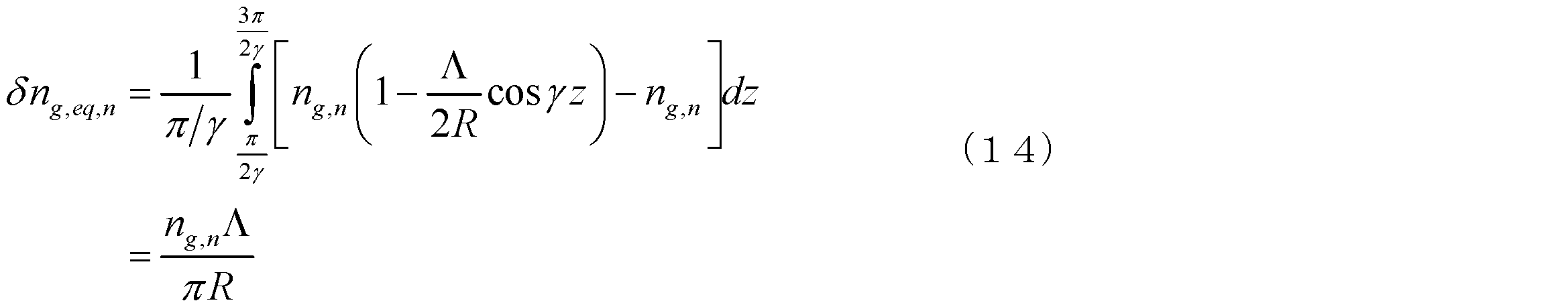
- the average equivalent group refractive index felt by light passing through the core n is a value obtained by adding the value of the equation (14) to the actual group refractive index ng, n .
- the group delay difference generated between the core m and the core n is a value represented by the following formula (17).
- the group refractive index ng of a certain mode of a certain core is expressed by the following formula (18), where ⁇ is the propagation constant of the certain mode, and ⁇ is the angular frequency of light.
- the propagation constant ⁇ of a certain mode is affected by surrounding cores.
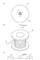
- FIGS. 1 to 3 show cross-sectional structures and the like of multi-core optical fibers 1a to 1c in which a plurality of cores 10 are arranged in a clad 20. That is, as a core arrangement in which adjacent cores have high crosstalk (for example, ⁇ 15 dB or more), the multi-core optical fiber 1a shown in FIG.
- FIG. 1A is equally spaced (core spacing ⁇ 1 ) on the same circle. It is desirable that the core 10 is disposed.
- FIG. 1B shows a state of the multi-core optical fiber 1a wound around a bobbin 30 (having a body portion having a radius R bobbin (m) along the central axis AX) around which the multi-core optical fiber 1a is wound.
- FIG. 1C shows a multi-core optical fiber transmission system using the multi-core optical fiber 1a as a transmission line.
- a transmitter 111 is optically connected to one end of the multi-core optical fiber 1a, and a receiver 112 is optically connected to the other end.
- Various multi-core optical fibers described below may be wound around the bobbin 30.
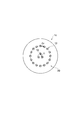
- a core group in which a plurality of cores 10 are arranged at equal intervals on the same circle (in the example of FIG. 2, the core intervals ⁇ 1 , ⁇ 2 , ⁇ a plurality of three core groups) constituted by arranged core 10 in 3, the plurality of cores 10 in the core gun has the same structure within each core-gun, cross cores adjacent in the core-gun It is also desirable that the talk be -15 dB or more. At this time, it is desirable that the core groups are sufficiently separated so that the crosstalk between the core groups is ⁇ 15 dB or less.
- a multi-core optical fiber 1c shown in FIG. it is further desirable that “the cores belonging to all the core groups are arranged on a plurality of concentric circles”. That is, in the example of FIG. 3, the core 10 is arranged with the core interval ⁇ 1 on the circumference of the inner circle, and the core 10 is arranged with the core interval ⁇ 2 on the circumference of the outer circle.
- the core intervals ⁇ 1 to ⁇ 3 are defined by the shortest distance between the centers of adjacent cores.
- the dispersion of the group delay difference generated in one section between two adjacent phase matching points is a value represented by the following equation (19), and when the fiber length is L
- the number N of phase matching points in the MCF can be obtained by the following equation (20).
- ⁇ may be regarded as a value obtained by averaging the absolute value of the number of rotations per fiber length in the fiber longitudinal direction.
- ⁇ ⁇ is considered to be the root mean square of the inter-core DGD, in order to reduce the inter-core DGD, it is desirable that the core interval ⁇ is smaller, and the fiber bending radius R is larger. It can be seen that a larger twist rate ⁇ is desirable.
- inter-core crosstalk can be compensated for by the MIMO technique, and it is not necessary to increase the core interval ⁇ to reduce crosstalk.
- ⁇ is 25 ⁇ m or less.
- a short core interval is preferable, a short core interval with ⁇ of 20 ⁇ m or less is more preferable, a short core interval with ⁇ of 15 ⁇ m or less is further preferable, and a short core interval with ⁇ of 10 ⁇ m or less is more preferable.
- the sampling rate of the signal (the number of samplings per unit time) is f sample
- the number of taps of 4 ⁇ ⁇ f sample or more in order to reflect the power of 95.44% or more of the original signal in the MIMO calculation, the number of taps of 4 ⁇ ⁇ f sample or more.
- f sample needs to be set at a frequency more than twice the symbol rate f symbol , in order to reflect the power of 95.44% or more of the original signal in the MIMO calculation, it is more than 8 ⁇ ⁇ f symbol It is necessary to set the number of taps. Further, in order to reflect 99.74% or more of the original signal in the MIMO calculation, it is necessary to set the number of taps equal to or greater than 12 ⁇ ⁇ f symbol on the time axis. .
- the following formula (22) needs to be satisfied in order to reflect the power of 95.44% or more of the original signal in the MIMO calculation. Means that. Further, in order to reflect the power of 99.74% or more of the original signal in the MIMO calculation, it means that the following formula (23) needs to be satisfied.
- the MCF satisfy the following equation (24) in order to reflect the power of 95.44% or more of the original signal in the MIMO calculation. In order to reflect 99.74% or more of the power of the original signal in the MIMO calculation, it is more desirable that the MCF satisfies the following formula (25).
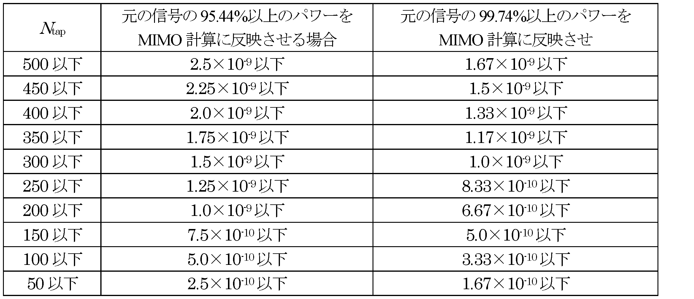
- the number of taps is 500 or less, 450 or less, 400 or less, 350 or less, 300, hereinafter, 250 or less, 200 or less, 150 or less, 100 or less, in order to 50 below, the desirable 2n g ⁇ / (cR) ⁇ (L / ⁇ ) 1/2 that it is ready to meet the fiber, wherein Table 1 shows the results calculated using (24) and formula (25).
- the MCF preferably satisfies the following formula (26) in order to reflect the power of 95.44% or more of the original signal in the MIMO calculation. In order to reflect the power of 99.74% or more of the original signal in the MIMO calculation, it is more desirable that the MCF satisfy the following formula (27).
- Table 2 shows the result of calculating ⁇ / (cR) ⁇ ( ⁇ ) ⁇ 1/2 using the equations (26) and (27).
- Table 4 shows.
- the number of taps is set.
- the fiber is in a state of satisfying 2 ng ⁇ / c ⁇
- Table 5 shows the results of calculating ( ⁇ ) ⁇ 1/2 using the equations (26) and (27).
- the number of taps is 500 or less, 450 or less, 400 or less, 350 or less, 300 or less, 250 or less, 200 or less, 150 or less, 100 or less, In order to make it 50 or less, it is shown in Table 6 that 2n g ⁇ / c ⁇ ( ⁇ ) ⁇ 1/2, which is desirably in a state where the fiber is satisfied, is calculated using Equation (26) and Equation 29) Show.
- the number of taps is set.
- the fiber is in a state of satisfying 2 ng ⁇ / c ⁇
- Table 7 shows the values obtained by calculating ( ⁇ ) ⁇ 1/2 using the equations (26) and (27).
- the number of taps is 500 or less, 450 or less, 400 or less, 350 or less, 300 or less, 250 or less, 200 or less, 150 or less, 100 or less,
- 2 ng ⁇ / c ⁇ ( ⁇ ) ⁇ 1/2 which is desirably in a state where the fiber is satisfied, is calculated using Equation (26) and Equation (27).
- ⁇ ⁇ / L 1/2 can be suppressed to be equal to or less than PMD in general-purpose single mode fiber (SSMF), or at least 10 times or less, the increase in the number of taps can be suppressed to 10 times or less. Therefore, it is more desirable.
- the SSMF PMD is typically at most 0.5 ps / km 1/2 (ie, about 1.58 ⁇ 10 ⁇ 14 s / m 1/2 ) or less.
- ⁇ ⁇ / L 1/2 is 10 times or less than 0.5 ps / km 1/2 , that is, 5.0 ps / km 1/2 (ie, about 1.58 ⁇ 10 ⁇ 13 s / m 1/2 ) or less.
- ⁇ ⁇ / L 1/2 is 5 times or less than 0.5 ps / km 1/2 , that is, 2.5 ps / km 1/2 (ie, about 7.91 ⁇ 10 ⁇ 14 s / m 1/2 ) or less.
- ⁇ ⁇ / L 1/2 is not more than twice of 0.5 ps / km 1/2 , that is, not more than 1.0 ps / km 1/2 (that is, about 3.16 ⁇ 10 ⁇ 14 s / m 1/2 ).
- ⁇ ⁇ / L 1/2 equal to 0.5 ps / km 1/2 (ie, about 1.58 ⁇ 10 ⁇ 13 s / m 1/2 ) or less
- the unit of each parameter is L (m), ⁇ (m), c (m / s), R (m), and ⁇ (rad / m).
- the equations (28) to (31 ) in order to meet the 2n g ⁇ / (cR) ⁇ ( ⁇ ) -1/2 preferably satisfies the multi-core optical fiber of the present invention shown in Table 10.
- N tap and f symbol a desirable relationship between N tap and f symbol at the time of transmission using the multicore optical fiber of the present invention that satisfies Expression (28) will be considered.
- N tap and f symbol satisfy Expression (22)
- the power of 99.74% or more of the original signal is reflected in the MIMO calculation.
- N tap and f symbol satisfy the formula (23).
- the N tap is increased, and the calculation amount is increased.
- a plurality of cores are arranged in a state of being physically close and optically coupled.
- An example of a cross-sectional view of such a multi-core optical fiber is shown in FIG.
- a plurality of cores 10 are arranged close to each other, and a clad 20 is provided around the cores 10.
- the plurality of cores 10 may be in physical contact with each other, but input / output of signals to / from each core 10 becomes easier if they are separated without being in contact with each other.
- the edges of the cores 10 are separated from each other by at least about 1 ⁇ m or more, more desirably, the edges of the cores 10 are separated from each other by at least about 5 ⁇ m, and the edges of the cores 10 are at least about 10 ⁇ m or more. It is desirable to be separated.
- the optically coupled state means that the crosstalk between the cores is sufficiently large.
- the crosstalk between adjacent cores is preferably ⁇ 15 dB or more, more preferably ⁇ 10 dB or more, further preferably ⁇ 5 dB or more, and more preferably about 0 dB.
- the value given as ⁇ up to this point is at least the “shortest distance between the centers of a plurality of cores”. Desirably, "the longest distance between the centers of each of a plurality of cores physically close and optically coupled" is more desirable.
- the multi-core optical fiber according to the present embodiment includes a core group composed of cores in which some but not all of a plurality of built-in cores are physically close and optically coupled. It is preferable that a plurality of cores are formed and the crosstalk between the core groups is appropriately suppressed.
- the crosstalk between adjacent cores in the core group is preferably ⁇ 15 dB or more, more preferably ⁇ 10 dB or more, further preferably ⁇ 5 dB or more, and further preferably about 0 dB.
- the crosstalk between the core groups is preferably at least -16.7 dB or less, more preferably -20 dB or less, and further preferably -30 dB or less. An example of a cross-sectional view of such a multi-core optical fiber is shown in FIG.
- FIG. 4 In the multi-core optical fiber 2 shown in FIG. 5, seven core groups 11 composed of seven cores 10 are formed in the fiber, and these are covered with a clad 20. These numbers are not limited to this value. Moreover, the example of FIG. 4 can also be said to be a case where there is one core group (see FIG. 1A). When such an MCF is used as a transmission path, when MIMO technology is individually applied to separation / decoding of spatially multiplexed signals in the individual core group 11, and MIMO technology is not applied to all cores as a unit, This is preferable because the amount of calculation can be reduced.
- the multi-core optical fiber transmission system using the multi-core optical fiber according to the present embodiment as a transmission path does not multiplex a signal into a plurality of super modes in which the core group 11 is guided integrally (that is, When coupling from the transmitter to the multi-core optical fiber, each signal for spatial multiplexing of the transmitter is coupled to each super mode guided by the core group of the MCF, and each super mode of the MCF is coupled to the receiver from the multi-core optical fiber to the receiver.
- the signals are multiplexed into the spatial mode guided by each core 10 in the core group 11 (when coupling from the transmitter to the MCF)
- Each signal for spatial multiplexing of the transmitter is coupled to a spatial mode that is individually guided by each core of the multicore optical fiber.
- Each signal before MIMO receiver processing from the spatial modes core optical fiber to spatial separation it is possible to reduce the DGD between spatial modes are used for multiplexing.
- each of the cores built in the multi-core optical fiber according to the present embodiment operates in a single mode. This is because the occurrence of inter-mode DGD (ie, DMD) within the same core can be suppressed.
- DGD inter-mode DGD
- each core included in a core group composed of physically adjacent and optically coupled cores operates in a single mode means that “the core group is the number of cores included in the core group. In other words, it is guided to the spatial mode of the same order, but the spatial mode of the higher order is cut off.
- each of the cores included in the MCF according to the present embodiment desirably guides a plurality of spatial modes.
- each built-in core guides a plurality of spatial modes so that the core modes of the same order between cores or different orders can be obtained. Random mode coupling between the core modes can be generated at each phase matching point. Therefore, the multimode optical fiber according to the present embodiment can achieve both a high spatial mode density and a low DGD.
- the cores incorporated in the multi-core optical fiber according to the above-described embodiment perform multi-mode operation, it is desirable that the DMD is sufficiently small.
- FIG. 6 an example is shown in which the bending radius of the multi-core optical fiber can be controlled by appropriate cabling.
- An optical fiber cable (multi-core optical fiber cable) 300 shown in FIGS. 6A and 6B includes a center member 310 and a plurality of optical fibers 100 wound around the center member 310 at a predetermined pitch.
- a presser winding 250 wound on a plurality of optical fibers so as to maintain the wound state, and a jacket 200 covering the periphery of the presser winding 250 are provided.
- the optical fiber cable 300 is also applicable to the transmission path of the multi-core optical fiber transmission system shown in FIG.
- the multi-core optical fibers 1 and 2 described above can also be applied to the transmission path of the multi-core optical fiber transmission system shown in FIG.
- the optical fiber 100 includes a multi-core optical fiber 100A and a resin coating 130 that entirely covers the multi-core optical fiber 100A.
- Each of the plurality of optical fibers 100 is bent at a certain radius of curvature by being wound around the central member 310 at a predetermined pitch along the longitudinal direction thereof.
- the jacket 200 covers the entire presser winding 250 so as to protect the optical fiber 100 from external force.
- FIG. 6B the optical fiber 100 is shown with only one core for the sake of simplicity, but in reality, all the optical fibers 100 included in the optical fiber cable 300 are wound around the central member 310. ing.
- the multi-core optical fiber As described above, according to the multi-core optical fiber, the multi-core optical fiber cable, and the multi-core optical fiber transmission system according to the present embodiment, it is possible to perform calculation using the MIMO technique effectively.
- this invention is not limited to the said embodiment, A various change can be made.
- MMF multi-core optical fiber
Landscapes
- Physics & Mathematics (AREA)
- General Physics & Mathematics (AREA)
- Optics & Photonics (AREA)
- Optical Communication System (AREA)
- Light Guides In General And Applications Therefor (AREA)
- Optical Fibers, Optical Fiber Cores, And Optical Fiber Bundles (AREA)
Abstract
本発明は、MIMO技術を効果的に用いた計算を可能にするマルチモード光ファイバに関する。当該マルチモード光ファイバは、複数のコアと、クラッドを備え、コアファイバ軸を中心に回転しており、平均捻じれ率γ(rad/m)、コアの中心間最短距離Λ(m)、群屈折率ng、使用時曲げ半径をR(m)、真空中の光速c(m/s)、円周率πで規定される条件式が、一例として、7.91×10-12(s/m1/2)以下となる。
Description
本発明は、マルチコア光ファイバ、マルチコア光ファイバケーブル、および、マルチコア光ファイバ伝送システムに関するものである。
所定軸に伸びたコアの内部に光を閉じ込めて伝送する光ファイバにおいて偏波モード分散(PMD)を低減させるために、コアを捻る技術が用いられる。例えば、特許文献1では、シングルコア光ファイバの線引き時に、溶融された状態のガラスを捻る(スピン)ことで、コアが非円であることや円対称ではない残留応力の影響を特定の方向に偏らせずランダマイズし、ファイバ自体に起因するPMDを減少させる構成が示されている。また、特許文献2では、ガラスが固化した後に、シングルコア光ファイバを捻る(ツイスト)ことで、ファイバ曲げや側圧等のファイバの外部に起因するPMDを減少させる構成が示されている。
また、マルチコア光ファイバにおいてもコアを捻る技術について検討されている。例えば、非特許文献1では、複数のコア間のクロストークを小さくして信号同士の干渉を抑えた非結合型マルチコア光ファイバにおいて、クロストークの大きさ(統計的平均値)は、少なくとも光ファイバの捻れに依存しないということが示されている。また、非特許文献2では、単位長さあたりの捻れレートを精密にコントロールし、且つ、100回転/m程度の一定の短ピッチとした場合に、非結合型マルチコア光ファイバにおけるコア間クロストークを大きく低減することができる可能性を示すシミュレーション結果が示されている。
T.Hayashi et al., "CrosstalkVariation of Multi-Core Fibre due to Fibre Bend,"ECOC2010,We.8.F.6
J.M. Fini et al., "Crosstalkin multicore fibers with randomness: gradual drift vs. short-length variations,"Optics Express, vol.20, no. 2, pp.949-959
R. Ryf, et al.,"Space-DivisionMultiplexed Transmission over 4200-km 3-Core Microstructured Fiber,"OFC/NFoEC2012paper PDP5C.2, March 8, 2012
発明者は、従来のマルチコア光ファイバについて検討した結果、以下のような課題を発見した。すなわち、近年、MIMO(Multiple-Input and
Multiple-Output)技術を用いて、空間モード間のクロストークを補償し、空間多重伝送を行う技術が用いられるようになった。しかしながら、空間多重伝送の場合は、空間モード間の群遅延差(空間モード間DGD)が大きいことに由来し、MIMO技術を用いたクロストーク補償のための計算(MIMO計算)の負荷が大きいという課題があった。なお、非特許文献3には、結合型マルチコア光ファイバ(コア間のクロストークの高いマルチコア光ファイバ)を用いて信号を伝送し、クロストークにより混ざり合った各コアの信号をMIMO技術により分離、復号する手法が記載されている。
Multiple-Output)技術を用いて、空間モード間のクロストークを補償し、空間多重伝送を行う技術が用いられるようになった。しかしながら、空間多重伝送の場合は、空間モード間の群遅延差(空間モード間DGD)が大きいことに由来し、MIMO技術を用いたクロストーク補償のための計算(MIMO計算)の負荷が大きいという課題があった。なお、非特許文献3には、結合型マルチコア光ファイバ(コア間のクロストークの高いマルチコア光ファイバ)を用いて信号を伝送し、クロストークにより混ざり合った各コアの信号をMIMO技術により分離、復号する手法が記載されている。
これに対して、空間多重伝送に用いられるような結合型マルチコア光ファイバでは、各コアにおける光の封じ込めを強めることやコア間隔を大きくすることでスーパーモード間のDGDを低減させることは既に知られているものの、個別のコアの空間モード間のDGD(コア間DGD)については検討が必ずしも十分ではなく、コアを捻った(スピン・ツイスト)場合のコア間DGDに対する影響についても検討されておらず、MIMO技術を用いるために好ましいマルチコア光ファイバを選択することが困難であった。
本発明は上述のような課題を解決するためになされたものであり、MIMO技術を効果的に用いた計算を可能にするマルチコア光ファイバ、マルチコア光ファイバケーブル、および、マルチコア光ファイバ伝送システムを提供することを目的としている。
本実施形態に係るマルチコア光ファイバは、第1の態様として、所定軸(当該マルチコア光ファイバの長手方向に沿って伸びる軸)に沿ってそれぞれ伸びるとともに該所定軸に対して垂直な断面上に配置された複数のコアと、複数のコアそれぞれを一体的に取り囲んだクラッド領域とを備え、複数のコアは、所定軸を中心に螺旋状に回転している。この第1の態様に係るマルチコア光ファイバは、当該マルチコア光ファイバの、単位長さ当たりに複数のコアが回転する角度の絶対値を当該マルチコア光ファイバの長手方向に沿って平均した値で規定される平均捻じれ率をγ(rad/m)とし、複数のコアそれぞれの中心の間における最短距離をΛ(m)とし、複数のコアそれぞれにおける基底モードに対する群屈折率をngとし、当該マルチコア光ファイバの使用時における曲げ半径で規定される使用時曲げ半径をR(m)とし、真空中の光速をc(m/s)とし、円周率をπとするとき、以下の第1~第3の条件のうち少なくとも何れかの条件を満たし、且つ、以下の第4~第5の条件のうち少なくとも何れかの条件を満たす。
なお、上記第1の条件は、下記の式(1)が7.91×10⁻¹²(s/m1/2)以下であることで規定される。上記第2の条件は、半径Rbobbin(m)のボビンに巻かれた状態において、下記の式(2)が7.91×10-12×1/Rbobbin(s/m1/2)以下であることで規定される。上記第3の条件は、最短距離Λが約25×10-6m以下であり、且つ、平均捻じれ率γが約4.72rad/m以上であることで規定される。上記第4の条件は、最短距離Λが約25×10-6m以下であることで規定される。上記第5の条件は、最も近い隣接コア同士のクロストークが-15dB以上であることで規定される。


上記第1の態様に適用可能な第2の態様として、半径Rbobbin(m)のボビンに巻かれた状態において、上記式(2)は7.91×10-12×0.2/Rbobbin(s/m1/2)以下であるのが好ましい。また、上記第1および第2の態様のうち少なくとも何れかの態様に適用可能な第3の態様として、上記第1の条件が、上記式(1)が1.58×10-13(s/m1/2)以下であることで規定され、上記第2の条件が、半径Rbobbin(m)のボビンに巻かれた状態において、上記式(2)が1.58×10-13×1/Rbobbin(s/m1/2)以下であることで規定され、上記記第1~第2の条件のうち少なくとも何れかの条件を満たすのが好ましい。上記第1~第3の態様のうち少なくとも何れかの態様に適用可能な第4の態様として、半径Rbobbin(m)のボビンに巻かれた状態において、上記式(2)は1.58×10-13×0.2/Rbobbin(s/m1/2)以下であるのが好ましい。上記第1~第4の態様のうち少なくとも何れかの態様に適用可能な第5の態様として、使用時曲げ半径Rは1m以上であるのが好ましい。上記第1~第5の態様のうち少なくとも何れかの態様に適用可能な第6の態様として、使用時曲げ半径Rは0.2m以上であるのが好ましい。
さらに、上記第1~第6の態様のうち少なくとも何れかの態様に適用可能な第7の態様として、当該マルチコア光ファイバは、複数のコアのうち断面において同一円の円周上に等間隔で配置された複数のコアにより構成された少なくとも1つのコア群を備えてもよい。この場合、コア郡に属するコアそれぞれは同一構造であり、該記コア郡に属するコアのうち隣接コア同士のクロストークは-15dB以上であるのが好ましい。更に、この第7の態様に係るマルチコア光ファイバは、上述の複数のコアにより複数のコア群が構成されてもよく、このように複数のコア群は配置された構成において、コア群間のクロストークが-15dB以下になる様に、それぞれのコア群は十分離された状態で配置される。なお、上記第1~第7の態様のうち少なくとも何れかの態様に適用可能な第8の態様として、当該マルチコア光ファイバにおいて上述の複数のコアにより複数のコア群が構成されている場合、全てのコア群に属するコアは、複数の同心円の何れかの円周上に配置されるのが好ましい。
本実施形態に係るマルチコア光ファイバケーブルは、第9の態様として、所定軸に沿ってそれぞれ伸びるとともに該所定軸に対して垂直な断面上に配置された複数のコアと、複数のコアそれぞれを一体的に取り囲んだクラッド領域とを備えたマルチコア光ファイバを内蔵し、複数のコアは、前記所定軸を中心に回転している。この第9の態様に係るマルチコア光ファイバケーブルは、マルチコア光ファイバの、単位長さ当たりに複数のコアが回転する角度の絶対値を該マルチコア光ファイバの長手方向に沿って平均した値で規定される平均捻じれ率をγ(rad/m)とし、複数のコアそれぞれの中心の間における最短距離をΛ(m)とし、複数のコアそれぞれにおける基底モードに対する群屈折率をngとし、マルチコア光ファイバの使用時における曲げ半径で規定される使用時曲げ半径をR(m)とし、真空中の光速をc(m/s)とし、円周率をπとするとき、下記の式(3)が7.91×10-12(s/m1/2)以下となるような状態を保持して、マルチコア光ファイバが内蔵されている。

上記第9の態様に適用可能な第10の態様として、上記式(3)は1.58×10⁻¹³(s/m1/2)以下となるような状態を保持して、マルチコア光ファイバが内蔵されるのが好ましい。また、上記第9および第10の態様のうち少なくとも何れかの態様に適用可能な第11態様として、当該マルチコア光ファイバケーブルにおいて、マルチコア光ファイバは、その長手方向に沿った曲げ半径の平均値が0.2m以上となるように内蔵されるのが好ましい。上記第9~11の態様のうち少なくとも何れかの態様に適用可能な第11態様として、最短距離Λは25×10-6m以下であるのが好ましい。更に、上記第9~12の態様のうち少なくとも何れかの態様に適用可能な第13態様として、複数のコアのうち最も近い隣接コア同士のクロストークが-15dB以上であるのが好ましい。
本実施形態に係るマルチコア光ファイバ伝送システムは、第14の態様として、所定軸に沿ってそれぞれ伸びるとともに該所定軸に対して垂直な断面上で配置された複数のコアと、複数のコアそれぞれを一体的に取り囲んだクラッド領域とを備えたマルチコア光ファイバを伝送路として用いる。この第14の態様に係るマルチコア光ファイバ伝送システムは、マルチコア光ファイバの、単位長さ当たりに複数のコアが回転する角度の絶対値を当該マルチコア光ファイバの長手方向に沿って平均した値で規定される平均捻じれ率をγ(rad/m)とし、複数のコアそれぞれの中心の間における最短距離をΛ(m)とし、複数のコアそれぞれにおける基底モードに対する群屈折率をngとし、マルチコア光ファイバの、その長手方向に沿った曲げ半径の平均値で規定される長手方向平均値をR(m)とし、真空中の光速をc(m/s)とし、円周率をπとし、信号変調のシンボルレートをfsymbol(Baud)とするとき、MIMO技術による復号計算を行う際のタップ数Ntapが、以下の式(4)で規定される関係を満たすように設定される。

なお、上記第14の態様に適用可能な第15の態様として、最短距離Λが25×10-6m以下であるのが好ましい。
本実施形態に係るマルチコア光ファイバは、第第16の態様として、上記第1~第8の態様のうち少なくとも何れかの態様に係るマルチコア光ファイバが伝送路として適用されても良い。この場合、第16の態様に係るマルチコア光ファイバ伝送システムにおいて、送信機と受信機の間のファイバリンク長をL(m)とし、信号変調のシンボルレートをfsymbol(Baud)とするとき、MIMO技術による復号計算を行う際のタップ数Ntapが、以下の式(5)で規定される関係を満たすように設定されるのが好ましい。

さらに、本実施形態に係るマルチコア光ファイバ伝送システムは、第17の態様として、上記第9~第13の態様のうち少なくとも何れかの態様に係るマルチコア光ファイバケーブルが伝送路として適用されても良い。この場合、第17の態様に係るマルチコア光ファイバにおいて、送信機と受信機の間のファイバリンク長をL(m)とし、信号変調のシンボルレートをfsymbol(Baud)とするとき、MIMO技術による復号計算を行う際のタップ数Ntapが、以下の式(6)で規定される関係を満たすように設定されるのが好ましい。

更に、上記第14~第17の態様のうち少なくとも何れかの態様に適用可能な第18の態様として、複数のコアのうち最も近い隣接コア間のクロストークが-15dB以上であるのが好ましい。
本発明によれば、MIMO技術を効果的に用いた計算を可能にするマルチコア光ファイバ、マルチコア光ファイバケーブル、および、マルチコア光ファイバ伝送システムが提供される。
以下、添付図面を参照して、本発明を実施するための形態を詳細に説明する。なお、図面の説明においては同一要素には同一符号を付し、重複する説明を省略する。
まず、以下の説明においては、MIMO(multiple-Input and Multiple-Output)技術においてコア間DGDの大きさが与える影響について説明した後、本実施形態に係るマルチコア光ファイバ等について説明する。
MIMO技術において、空間モード間のクロストークを補償し、空間多重(コア多重/モード多重)伝送を行う技術が知られているが、計算量の大きさから、実時間処理は実現されていない。具体的には、空間モード間の群遅延差(空間モード間DGD)が大きいと、その大きさに比例してMIMO計算を行う際の計算量も大きくする必要がある。例えば、DGDの無い場合に、MIMO技術を用いて、Mチャンネル分の混ざり合った信号(x1,・・・,xM)を元の信号(y1,・・・,yM)に分離する計算は、簡単にすると、下記の式(7)に示すことができる。

式(7)に示された行列計算では、計算量はMの二乗に比例する。ここで、光ファイバに於けるチャンネル数Mは、空間モード数と偏波モード数との積である。例えば、各コアがシングルモード動作するマルチコア光ファイバ(MCF)の場合は、コア数の2倍がチャンネル数Mとなる。一方、DGDがある場合は、有限インパルス応答(FIR)フィルタを用いた計算が必要となるので、MIMO技術を用いて、混ざり合った信号xを元の信号yに分離する計算は、y[n]およびx[n]をそれぞれ信号列として、用いた場合、下記の式(8)で示すことができる。

この場合、y[n]を複合するために必要な信号がDGDに由来してx[n-N]からx[n]の範囲に広がって分布するために、計算量が式(7)の場合と比較してN+1倍となる。
ここで、N+1のことを一般にタップ数Ntapといい、タップ数が少ないほど計算量を抑えることができる。DGDが小さければ、時間軸上の受信信号の広がりが小さくなりタップ数を小さくできる。シンボルレート(単位時間当たりの変調シンボル個数)が小さい場合、時間軸上での受信信号の広がりが一定であっても、単位時間当たりの信号サンプリング回数が小さくなるため、タップ数は小さくできるが、伝送信号の高速化のためにはシンボルレートは大きい方が望ましい。
このように、MIMO技術を用いた計算を行う場合、空間モード間のDGDは小さい方が望ましいので、数モードの光ファイバでは、DGD低減のための手法が幾つか報告されている。一方、結合型マルチコア光ファイバにおけるスーパーモード間のDGDは、各コアへの光の閉じ込めを強めるかコア間隔を離すことで低減できる可能性があることが知られている。しかしながら、個別のコアの空間モード間のDGD(コア間DGD)についてはあまり検討されておらず、光ファイバのスピンやツイストがコア間DGDに対してどのように影響するかについてもこれまで明らかではなかった。
これに対して、検討した結果をいかに説明する。なお、以下の説明においてコア間のクロストークの値を用いて議論する場合、その値は「クロストークの統計分布の平均値」をいう。例えば、コアmとコアnの間のクロストークの統計分布の平均値XTの場合、XT=Pnm/Pmmと定義した値を用いる。ただし、ここで、Pnmはコアmに光を入射した場合のコアnからの出射光パワーの統計的平均を意味する。
最初に、結合型MCFのコア間DGDの分布を、簡単のために2コアファイバについて考えてみる。
まず、非特許文献1によると、ファイバを曲げると、ファイバ内のコアの位置によって各コアの曲げ径が極僅かに異なるため、各コアの光路差も異なってくる。これを直線導波路として扱う場合、等価屈折率を用いる必要がある。等価屈折率は実際の屈折率に、(1+x/R)を掛けることで求められる。ただし、Rは基準とするコアの曲げ半径、xは曲げ径方向の基準コアからのずれ量である。よって、MCF中の各コアは、MCFの曲げと捻れにより異なる等価屈折率を持ち得る。
また、非特許文献2によるとMCFに含まれるコアmとコアnとの間のクロストーク、または、パワーの交換は、その殆どが、コアmとコアnとの等価屈折率が等しくなる位相整合点で発生することから、MCF中のクロストークを位相整合点でのみ離散的に起こるコア間のパワーの交換というようにモデル化することができる。
このとき、簡単のために、MCF中で等間隔に位相整合点が存在すると考え、各位相整合点でコアm中のパワーの半分がコアnに、コアn中のパワーの半分がコアmに移行すると考えて、DGDがファイバ長に対してどの様に変化するかを考える。
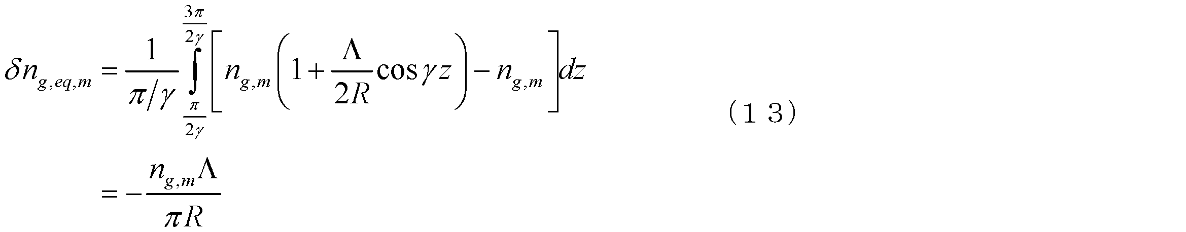
コアmとコアnの群屈折率をそれぞれng,mとng,nとし、コアmとコアnとの中間点を基準とすることで、曲げと捻れの影響を考慮したコアmの等価的な群屈折率を式(9)と表すことができ、コアnの等価群屈折率を式(10)と表すことができる。ただし、Λはコアmの中心とコアnの中心の間の距離(コア間隔)、θは、「コアmとコアnとの中間点」からみた「コアm」の、MCF断面上での位置の曲げ径方向に対する角度(rad)である。


ここで、簡単のために、MCFが一定の捻れレートγ(rad/単位長さ)で捻れている場合を考えるとθは式(11)のように表すことができる。

上記の式(9)~式(11)の場合を考えると、ある隣り合う2つの位相整合点に挟まれた1区間(長さπ/γ)は、下記の式(12)の範囲内になると考えられる。

このとき、簡単のためにRを一定とすると、コアmを通った光が式(12)の1区間で感じる平均等価群屈折率は、式(13)の値を実際の群屈折率ng,mに加えた値となる。
同様に、コアnを通った光の感じる平均等価群屈折率は、式(14)の値を実際の群屈折率ng,nに加えた値となる。
式(12)の区間に隣り合う区間では、式(13)と式(14)の符号を逆にした値をそれぞれ実際の群屈折率に加えた値が、それぞれのコアを通った光の感じる平均等価群屈折率となる。
ここで、隣り合う2つの位相整合点に挟まれた1区間の長さは、下記の式(15)で表すことができるので、コアm、コアnを通った光の群遅延に、隣り合う2つの位相整合点に挟まれた1区間ごとに、下記の式(16a)および式(16b)で示す変化が生じる(復号同順)。なお、ただし、cは真空中の光速を示す。


したがって、コアmとコアnの間で生じる群遅延差は、下記の式(17)で示す値となる。

ここで、上記数式(17)で示されるコア間の群遅延差を小さくする為には、まず、ng,m
=ng,nであることが、望ましい。ng,m =ng,nであるには、コアmとコアnが同一構造であることが望ましい。
=ng,nであることが、望ましい。ng,m =ng,nであるには、コアmとコアnが同一構造であることが望ましい。
より詳しく考えると、あるコアのあるモードの群屈折率ngは、前記あるモードの伝搬定数をβとし、光の角周波数をωとすると、下記の式(18)で表され、更に、前記あるモードの伝搬定数βは、周辺のコアの影響を受ける。

よって、MIMO計算によりクロストーク補償を行う必要のある高クロストークで結合している複数のコア同士で、それぞれのコアのモードの伝搬定数が等しくなり、さらに群屈折率が等しくなる為には、前記高クロストークで結合している複数のコアが同一構造を有し、且つ、それぞれのコアを基準とした他コアの配置が合同であることが望ましい。より具体的に説明するため、図1~図3には、複数のコア10がクラッド20内に配置されたマルチコア光ファイバ1a~1cの断面構造等が示されている。すなわち、隣接するコア同士が高クロストーク(例えば-15dB以上)となるコア配置として、図1(a)に示されるマルチコア光ファイバ1aの様に同一円上に等間隔(コア間隔Λ1)にコア10が配置されていることが望ましい。なお、図1(b)には、マルチコア光ファイバ1aが巻かれるボビン30(中心軸AXに沿って半径Rbobbin(m)の胴部を有する)に巻かれたマルチコア光ファイバ1aの様子が示されている。図1(c)には、マルチコア光ファイバ1aを伝送路として用いたマルチコア光ファイバ伝送システムが示されている。このマルチコア光ファイバ1aの一方の端部には送信機111が光学的に接続されており、他方の端部には受信機112は光学的に接続されている。以下に説明される種々のマルチコア光ファイバがボビン30に巻かれてもよい。また、図2に示されるマルチコア光ファイバ1bの様に、同一円上に等間隔に複数のコア10が配置されているコア群(図2の例では、それぞれコア間隔Λ1、Λ2、Λ3で配置されたコア10により構成された3つのコア群)を複数備え、コア郡内の複数のコア10はそれぞれのコア郡内で同一構造であり、コア郡内の隣接するコア同士のクロストークは-15dB以上であるのも望ましい。このとき、コア群間のクロストークが-15dB以下になる様に、それぞれのコア群は十分離れていることが望ましい。複数のコア群を備えるとき、更に、あるコア郡内のコアの伝搬定数への、他のコア群のコアからの影響を均一化する為には、図3に示されるマルチコア光ファイバ1cの様に、「全てのコア群に属するコアが、複数の同心円上に配置されていること」が、更に望ましい。すなわち、図3の例では、内側円の円周上にはコア間隔Λ1でコア10が配置され、外側円の円周上にコア間隔Λ2でコア10が配置されている。なお、コア間隔Λ1~Λ3は、隣接するコア同士の中心間の最短距離で規定される。これらマルチコア光ファイバ1b、1cも、図1(c)に示されたマルチコア光ファイバ伝送システムの伝送路に適用可能である。
ここで、ng=ng,m
=ng,nとすると、隣り合う2つの位相整合点に挟まれた1区間で生じる群遅延差の分散は、下記の式(19)で示す値となり、また、ファイバ長をLとしたときに、MCF中の位相整合点の数Nは、下記の数式(20)で求めることができる。


=ng,nとすると、隣り合う2つの位相整合点に挟まれた1区間で生じる群遅延差の分散は、下記の式(19)で示す値となり、また、ファイバ長をLとしたときに、MCF中の位相整合点の数Nは、下記の数式(20)で求めることができる。
上記の位相整合点間の群遅延と、位相整合点に於けるクロストーク(コアnとコアm間でのパワーの移行)を考慮すると、Nの数が十分に大きい場合中心極限定理により、MCF各コアのインパルス応答は、正規分布となり、前記正規分布の分散στ
2はστc
2Nとなると考えられる。上記の正規分布の標準偏差を、式(15)、式(19)および式(20)を用いて整理すると、下記の式(21)の通りとなる。
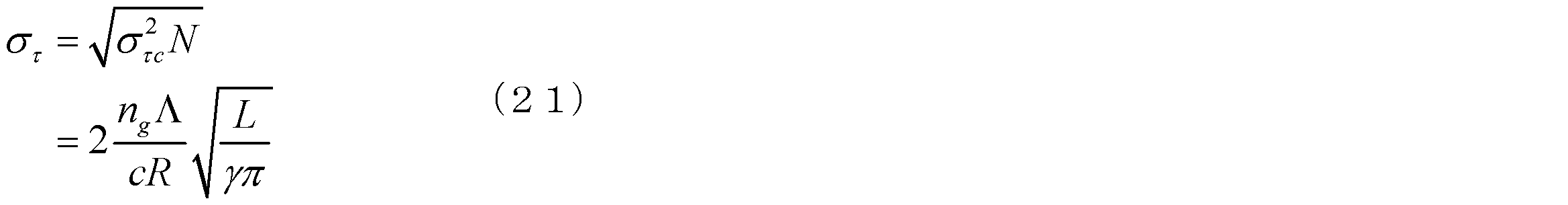
ここでは、γが一定の場合について考えたが、γをファイバ長さ当たりの前記回転の回数の絶対値をファイバ長手方向で平均した値とみなすこともできる。ここで、στはコア間DGDの二乗平均平方根と考えられることから、コア間DGDを小さくするためには、コア間隔Λが小さい方が望ましく、ファイバの曲げ半径Rが大きい方が望ましく、ファイバの捻れレートγが大きい方が望ましいことが分かる。
本実施形態に係るMCFを用いて伝送を行う場合、コア間クロストークはMIMO技術により補償可能であり、クロストーク低減のためにコア間隔Λを大きくする必要がないので、例えばΛが25μm以下の短いコア間隔が好適であり、Λが20μm以下の短いコア間隔が更に好適であり、Λが15μm以下の短いコア間隔が更に好適であり、Λが10μm以下の短いコア間隔が更に好適である。
ここで、例えば、元の信号の95.44%以上のパワーをMIMO計算に反映させるためには、時間軸上で4στ以上の時間をカバーできるようにタップ数を設定する必要がある。また、99.74%以上のパワーをMIMO計算に反映させるためには、時間軸上で6στ以上の時間をカバーできるようにタップ数を設定する必要がある。
ここで、信号のサンプリングレート(単位時間当たりのサンプリング回数)をfsampleとすると、元の信号の95.44%以上のパワーをMIMO計算に反映させるためには、4στfsample以上のタップ数を設定する必要があり、更に、元の信号の99.74%以上のパワーをMIMO計算に反映させるためには、時間軸上で6στfsample以上のタップ数を設定する必要がある。
また、fsampleは、シンボルレートfsymbolの倍以上の頻度に設定する必要があるので、元の信号の95.44%以上のパワーをMIMO計算に反映させるためには、8στfsymbol以上のタップ数を設定する必要があり、更に、元の信号の99.74%以上のパワーをMIMO計算に反映させるためには、時間軸上で12στfsymbol以上のタップ数を設定する必要がある。
つまり、所望のシンボルレートfsymbolおよびタップ数Ntapが与えられれば、元の信号の95.44%以上のパワーをMIMO計算に反映させるためには、下記の式(22)を満たす必要があることを意味する。また、元の信号の99.74%以上のパワーをMIMO計算に反映させるためには、下記の式(23)を満たす必要があることを意味する。


上記式(21)~式(23)を整理すると、元の信号の95.44%以上のパワーをMIMO計算に反映させるためには、MCFは下記の式(24)を満たすことが望ましく、また、元の信号の99.74%以上のパワーをMIMO計算に反映させるためには、MCFは下記の式(25)を満たすことがさらに望ましい。


ここで、fsymbolが例えば25GBaud(=2.5×10¹⁰Baud:1秒当たり2.5×10¹⁰シンボル)以上の場合に、タップ数を500以下、450以下、400以下、350以下、300以下、250以下、200以下、150以下、100以下、50以下にするためには、ファイバが満たす状態にあることが望ましい2ngΛ/(cR)・(L/γπ)1/2を、式(24)および式(25)を用いて計算したものを表1に示す。
また、所望の伝送距離がLで与えられる場合、元の信号の95.44%以上のパワーをMIMO計算に反映させるためには、MCFは下記の式(26)を満たすことが望ましく、また、元の信号の99.74%以上のパワーをMIMO計算に反映させるためには、MCFは下記の式(27)を満たすことがさらに望ましい。


ここで、例として、fsymbolが25GBaud(=2.5×1010Baud:1秒当たり2.5×1010シンボル)以上で少なくともL=100km=1×10⁵mの距離を伝送させる場合に、タップ数を500以下、450以下、400以下、350以下、300以下、250以下、200以下、150以下、100以下、50以下にするためには、ファイバが満たす状態にあることが望ましい2ngΛ/(cR)・(γπ)-1/2を、式(26)および式(27)を用いて計算したものを表2に示す。また、fsymbolが25GBaud(=2.5×1010Baud:1秒当たり2.5×1010シンボル)以上で少なくともL=1000km=1×106mの距離を伝送させる場合に、タップ数を500以下、450以下、400以下、350以下、300以下、250以下、200以下、150以下、100以下、50以下にするためには、ファイバが満たす状態にあることが望ましい2ngΛ/(cR)・(γπ)-1/2を、式(26)および式(27)を用いて計算したものを表3に示す。式(19)~式(20)を用いて計算し、表3にまとめた。すなわち、MCFは、2ngΛ/(cR)・(γπ)-1/2が表2または表3の値を満たすように、適切なΛとγの値を持ち、適切なRを保持するようにケーブル化されることが望ましい。


また、ケーブル化後または敷設後のMCF使用時においてMCFの曲げ半径Rを0.1mと仮定した場合、fsymbolが25GBaud(=2.5×10¹⁰Baud:1秒当たり2.5×10¹⁰シンボル)以上で少なくともL=100km=1×10⁵mの距離を伝送させる場合に、タップ数を500以下、450以下、400以下、350以下、300以下、250以下、200以下、150以下、100以下、50以下にするためには、ファイバが満たす状態にあることが望ましい2ngΛ/c・(γπ)-1/2を、式(26)および式(27)を用いて計算したものを表4に示す。また、fsymbolが25GBaud(=2.5×1010Baud:1秒当たり2.5×1010シンボル)以上で少なくともL=1000km=1×106mの距離を伝送させる場合に、タップ数を500以下、450以下、400以下、350以下、300以下、250以下、200以下、150以下、100以下、50以下にするためには、ファイバが満たす状態にあることが望ましい2ngΛ/c・(γπ)-1/2を、式(26)および式(27)を用いて計算したものを表5に示す。


また、ケーブル化後または敷設後のMCF使用時においてMCFの曲げ半径Rを1mと仮定した場合、fsymbolが25GBaud(=2.5×10¹⁰Baud:1秒当たり2.5×10¹⁰シンボル)以上で少なくともL=100km=1×10⁵mの距離を伝送させる場合に、タップ数を500以下、450以下、400以下、350以下、300以下、250以下、200以下、150以下、100以下、50以下にするためには、ファイバが満たす状態にあることが望ましい2ngΛ/c・(γπ)-1/2を、式(26)および式29)を用いて計算したものを表6に示す。また、fsymbolが25GBaud(=2.5×1010Baud:1秒当たり2.5×1010シンボル)以上で少なくともL=1000km=1×106mの距離を伝送させる場合に、タップ数を500以下、450以下、400以下、350以下、300以下、250以下、200以下、150以下、100以下、50以下にするためには、ファイバが満たす状態にあることが望ましい2ngΛ/c・(γπ)-1/2を、式(26)および式(27)を用いて計算したものを表7に示す。


また、ケーブル化後または敷設後のMCF使用時においてMCFの曲げ半径Rを10mと仮定した場合、fsymbolが25GBaud(=2.5×10¹⁰Baud:1秒当たり2.5×10¹⁰シンボル)以上で少なくともL=100km=1×10⁵mの距離を伝送させる場合に、タップ数を500以下、450以下、400以下、350以下、300以下、250以下、200以下、150以下、100以下、50以下にするためには、ファイバが満たす状態にあることが望ましい2ngΛ/c・(γπ)-1/2を、式(26)および式(27)を用いて計算したものを表8に示す。また、fsymbolが25GBaud(=2.5×1010Baud:1秒当たり2.5×1010シンボル)以上で少なくともL=1000km=1×106mの距離を伝送させる場合に、タップ数を500以下、450以下、400以下、350以下、300以下、250以下、200以下、150以下、100以下、50以下にするためには、ファイバが満たす状態にあることが望ましい2ngΛ/c・(γπ)-1/2を、式(26)および式(27)を用いて計算したものを表9に示す。

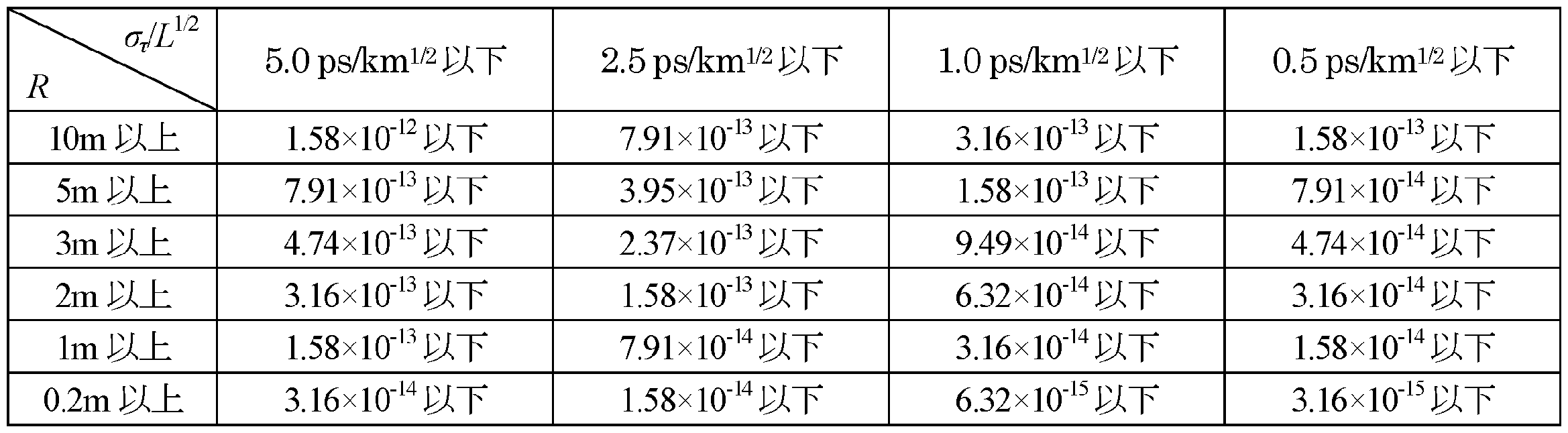
ここで、更に、στ/L1/2が汎用シングルモードファイバ(SSMF)におけるPMDと同等以下か、少なくとも10倍以下に抑えることができれば、タップ数の増加を10倍以下に抑えることができるため、さらに望ましい。SSMFのPMDは一般に最大でも0.5ps/km1/2(すなわち約1.58×10-14s/m1/2)以下である。
στ/L1/2が、0.5ps/km1/2の10倍以下、すなわち5.0ps/km1/2(すなわち約1.58×10-13s/m1/2)以下になるためには、上記式(21)に基づいて、本発明のマルチコア光ファイバは、下記の式(28)を満たすことが望ましい。また、στ/L1/2が0.5ps/km1/2の5倍以下、すなわち2.5ps/km1/2(すなわち約7.91×10-14s/m1/2)以下になるためには、下記の式(29)を満たすことが望ましい。さらに、στ/L1/2が0.5ps/km1/2の2倍以下、すなわち1.0ps/km1/2(すなわち約3.16×10-14s/m1/2)以下になるためには、下記の式(30)を満たすことが望ましい。そして、στ/L1/2が0.5ps/km1/2と同等(すなわち約1.58×10-13s/m1/2)以下になるためには、下記の式(31)を満たすことが望ましい。ただし、それぞれのパラメータの単位は、L(m)、Λ(m)、c(m/s)、R(m)、γ(rad/m)である。


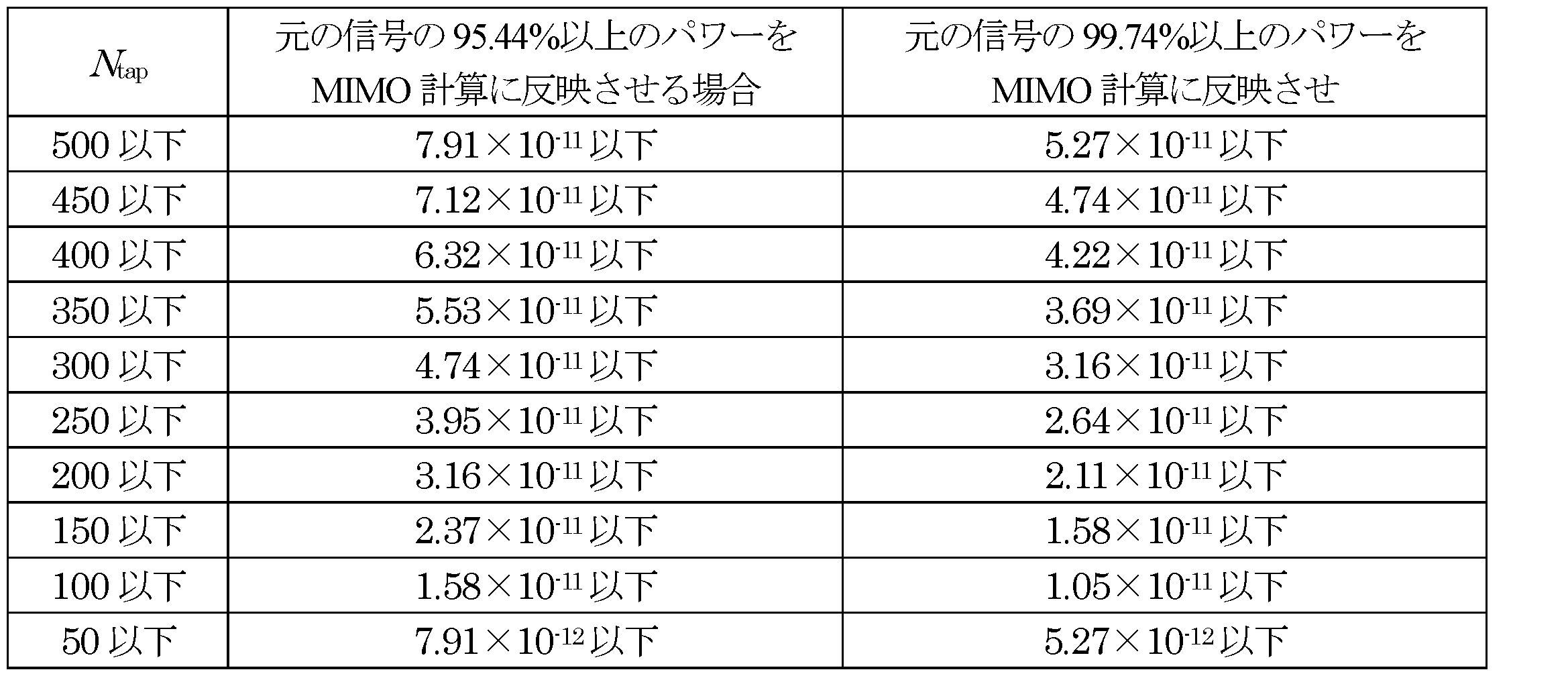
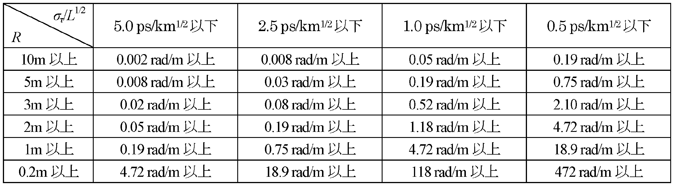
ケーブル化後または敷設後のMCF使用時においてMCFの曲げ半径Rを10m以上、5m以上、3m以上、2m以上、1m以上、0.2m以上と仮定した場合に、式(28)~式(31)を満たすために、本発明のマルチコア光ファイバが満たすことが望ましい2ngΛ/(cR)・(γπ)-1/2を表10に示す。また、ng=1.46、Λが25μm(=25×10-6m)以下と仮定した場合に、表10の値を実現するために望ましいγ(rad/m)の値を表11に示す。
例えば、一般的なテープスロット型ケーブルを考えた場合、ケーブル化後のファイバに付与される曲げ半径は0.2乃至2mの範囲にあるものが殆どなので、表10より、マルチコア光ファイバにおける2ngΛ/c・(γπ)-1/2が3.16×10-14以下であれば、一般的なテープスロット型ケーブルで当該マルチコア光ファイバをケーブル化した際には、στ/L1/2を5.0ps/km1/2以下にすることが可能になると考えられる。また、同様にして、表11より、Λが25μm(=25×10-6m)以下であり、且つ、γが約4.72rad/m以上であれば、一般的なテープスロット型ケーブルで当該マルチコア光ファイバをケーブル化した際には、στ/L1/2を5.0ps/km1/2以下にすることが可能になると考えられる。
ここで、使用時のファイバの曲げ半径をRとし、ボビン巻き状態でのファイバの曲げ半径をRbobbinとした場合に、使用時にστ/L1/2が目標Aを満たすためには、式(21)に基づいて式(32)を満たすことが望ましい。このとき、ボビン巻き時に満たすべき目標は式(33)より、AR/Rbobbinとなる。


次に、式(28)を満たす本発明のマルチコア光ファイバを用いた伝送時の望ましいNtapとfsymbolの関係について考える。元の信号の95.44%以上のパワーをMIMO計算に反映させる場合Ntapとfsymbolは式(22)を満たすことが望ましく、元の信号の99.74%以上のパワーをMIMO計算に反映させる場合Ntapとfsymbolは式(23)を満たすことが更に望ましいが、必要以上の割合のパワーをMIMO計算に反映させるとNtapの増加を招き、ひいては計算量の増加を招く。そこで、元の信号の95.44%以上且つ99.74%以下のパワーをMIMO計算に反映させることが望ましく、下記の式(34)を満たす様に、Ntapとfsymbolの関係を設定することが望ましく、また、上記式(21)より、下記の式(35)を満たすことが望ましい。


ここで、式(34)をNtap/fsymbolについて整理すると、下記の式(36)となる。

よって、στ/L1/2が5.0ps/km1/2(すなわち約1.58×10-13s/m1/2)以下のマルチコア光ファイバを用いて伝送を行う場合、式(36)から、Ntapとfsymbolの関係は、少なくとも下記の式(37)を満たすことが望ましい。なお、ここでは、fsymbolの単位はBaud、Lの単位はmである。

本実施形態に係るマルチコア光ファイバは、複数のコアが、物理的に近接し光学的に結合した状態で配置されているのが好適である。この様なマルチコア光ファイバの断面図の例を図4に示す。図4に示されたマルチコア光ファイバ1では、複数のコア10が近接配置され、その周囲にクラッド20が設けられている。複数のコア10同士は物理的に接触していてもよいが、接触せずに離間していた方が各コア10への信号の入出力が容易になる。したがって、各コア10の縁同士が少なくとも約1μm以上離れていることが望ましく、各コア10の縁同士が少なくとも約5μm以上離れていることが更に望ましく、各コア10の縁同士が少なくとも約10μm以上離れていることが望ましい。ここで、光学的に結合した状態とはコア間のクロストークが十分大きいことをいう。隣接コア間のクロストークは、-15dB以上が望ましく、-10dB以上が更に望ましく、-5dB以上が更に望ましく、おおよそ0dBが更に望ましい。コア間のDGDは、前述の通り、コア間隔が大きいほど大きくなることから、ここまでΛとして挙げられてきた値は、少なくともの「複数のコアそれぞれの中心の間の最短距離」であることが望ましく、「物理的に近接し光学的に結合した複数のコアそれぞれの中心の間の最長距離」であることが更に望ましい。
また、本実施形態に係るマルチコア光ファイバとしては、内蔵する複数のコアのうち、全てではない一部且つ複数のコアが、物理的に近接し光学的に結合したコアで構成されるコア群を複数個形成し、それぞれのコア群同士の間のクロストークは適切に抑圧された状態で配置されているのが好適である。コア群内の隣接コア同士の間のクロストークは-15dB以上であることが望ましく、-10dB以上が更に望ましく、-5dB以上が更に望ましく、おおよそ0dBが更に望ましい。コア群同士の間のクロストークは少なくとも-16.7dB以下であることが望ましく、-20dB以下であることが更に望ましく、-30dB以下であることが更に望ましい。この様なマルチコア光ファイバの断面図の例を図5に示す。
図5に示されたマルチコア光ファイバ2は、7個のコア10からなるコア群11が、ファイバ内に7個形成され、これらがクラッド20によりおおわれている。なお、これらの数はこの値に限られない。また、図4の例は、コア群が1つの場合ということも可能である(図1(a)参照)。このようなMCFを伝送路として用いる場合、個別のコア群11内における空間多重信号の分離・復号に個別にMIMO技術を適用し、全てのコアに一体としてMIMO技術を適用しない場合、MIMO計算の計算量を削減できるため好適である。
また、本実施形態に係るマルチコア光ファイバを伝送路として用いたマルチコア光ファイバ伝送システムは、上記のコア群11が一体として導波する複数のスーパーモードに信号を多重化するのではなく(すなわち、送信機からマルチコア光ファイバへの結合時に送信機の空間多重用の各信号をMCFのコア群が導波する各スーパーモードに結合し、マルチコア光ファイバから受信機への結合時にMCFの各スーパーモードから受信機のMIMO処理前の各信号を空間分離するのではなく)、上記のコア群11内の各コア10が導波する空間モードに信号を多重化する(送信機からMCFへの結合時に送信機の空間多重用の各信号をマルチコア光ファイバの各コアが個別に導波する空間モードに結合し、MCFから受信機への結合時にマルチコア光ファイバの各空間モードから受信機のMIMO処理前の各信号を空間分離する)ことで、多重化に用いている空間モード間のDGDを小さくすることができる。
また、本実施形態に係るマルチコア光ファイバが内蔵するコアは、それぞれがシングルモード動作することが望ましい。これは、同一コア内でのモード間DGD(すなわちDMD)の発生を抑止できるためである。ここで、「物理的に近接し光学的に結合したコアで構成されるコア群に含まれるコアそれぞれがシングルモード動作する」と言うことは、「コア群は、コア群に含まれるコア数と同じ次数の空間モードまでは導波するが、それよりも大きな次数の空間モードはカットオフされる」と言い換えることも出来る。一方、本実施形態に係るMCFが内蔵するコアは、それぞれが複数の空間モードを導波することが望ましい。これは、複数の空間モードを導波するコアにおいて、空間モード間でのランダムな結合を長手方向に高い頻度で発生させるためである。単一のコアや、非結合の複数のコアそれぞれが、複数の空間モードを導波する場合は、空間モード間のランダムな結合を、長手方向に高い頻度で発生させることは難しい。このようなランダムな結合は、せいぜい数kmごとのファイバ接続点で発生する程度である。これに対して、本実施形態に係るマルチコア光ファイバでは、内蔵されるコアそれぞれが複数の空間モードを導波する様にすることで、コア間で同一次数のコアモード同士の間や、異なる次数のコアモード同士の間におけるランダムなモード結合を、それぞれの位相整合点で発生させることができる。そのため、本実施形態に係るマルチモード光ファイバでは、高い空間モード密度と低いDGDの両立が可能になる。上記実施形態に係るマルチコア光ファイバに内臓されるコアは、それぞれがマルチモード動作する場合、DMDが十分小さいことが望ましい。
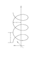
また、本実施形態に係るマルチコア光ファイバをケーブル化する際には、適切なケーブル化によりマルチコア光ファイバの曲げ半径を制御することができる図6にその一例を示す。図6(a)および図6(b)に示された光ファイバケーブル(マルチコア光ファイバケーブル)300は、中心部材310と、中心部材310に所定ピッチで巻きつけられた複数の光ファイバ100と、その巻きつけられた状態を保持するように複数の光ファイバ上に巻きつけられた押え巻き250と、押え巻き250の周りを覆う外被200を備える。なお、光ファイバケーブル300も、図1(c)に示されたマルチコア光ファイバ伝送システムの伝送路に適用可能である。また、上述のマルチコア光ファイバ1、2も、図1(c)に示されたマルチコア光ファイバ伝送システムの伝送路に適用可能である。光ファイバ100は、マルチコア光ファイバ100Aと、マルチコア光ファイバ100Aを全体的に覆った樹脂被覆130からなる。複数の光ファイバ100それぞれは、その長手方向に沿って所定のピッチで中心部材310に巻きつけられることにより、一定の曲率半径の曲げが付与されている。外被200は、光ファイバ100を外力から保護するように、押え巻き250の全体を覆っている。なお、図6(b)において、光ファイバ100は、記載簡略のため、1芯のみ記載しているが、実際には当該光ファイバケーブル300に含まれる全光ファイバ100が中心部材310に巻かれている。図6(a)および図6(b)の光ファイバゲーブルのように、テンションメンバなどの所定の軸の周囲にMCFを螺旋状に巻き付けるようにケーブル化すれば、螺旋の半径rhと螺旋のピッチLPを調整することで、MCFの曲げ半径Rを制御することができる。図7に、螺旋の半径rhと螺旋のピッチLPの関係を示す。所定軸の長手方向をz軸として、このz軸に直交するxy平面上でz軸を基準に極座標(r,θ)をとると、MCFは、r=rh、θ=2πz/LPとなる配置を示している。
以上のように、本実施形態にかかるマルチコア光ファイバ、マルチコア光ファイバケーブル、およびマルチコア光ファイバ伝送システムによれば、MIMO技術を効果的に用いた計算を行うことが可能となる。なお、本発明は上記実施形態に限定されず種々の変更を行うことができる。
1a~1c、1、2…マルチコア光ファイバ(MCF)、10…コア、11…コア群、20…クラッド、300…光ファイバケーブル。
Claims (18)
- 所定軸に沿ってそれぞれ伸びるとともに前記所定軸に対して垂直な断面上に配置された複数のコアと、前記複数のコアそれぞれを一体的に取り囲んだクラッド領域とを備えたマルチコア光ファイバであって、
前記複数のコアは、前記所定軸を中心に回転しており、
当該マルチコア光ファイバの、単位長さ当たりに前記複数のコアが回転する角度の絶対値を当該マルチコア光ファイバの長手方向に沿って平均した値で規定される平均捻じれ率をγ(rad/m)とし、
前記複数のコアそれぞれの中心の間における最短距離をΛ(m)とし、
前記複数のコアそれぞれにおける基底モードに対する群屈折率をngとし、
当該マルチコア光ファイバの使用時における曲げ半径で規定される使用時曲げ半径をR(m)とし、
真空中の光速をc(m/s)とし、
円周率をπとするとき、
第1の条件が、下記の式(1)が7.91×10⁻¹²(s/m1/2)以下であることで規定され、
第2の条件が、半径Rbobbin(m)のボビンに巻かれた状態において、下記の式(2)が7.91×10-12×1/Rbobbin(s/m1/2)以下であることで規定され、
第3の条件が、前記最短距離Λが約25×10-6m以下であり、且つ、前記平均捻じれ率γが約4.72rad/m以上であることで規定され、
第4の条件が、前記最短距離Λが約25×10-6m以下であることで規定され、
第5の条件が、最も近い隣接コア同士のクロストークが-15dB以上であることで規定され、
前記第1~第3の条件のうち少なくとも何れかの条件を満たし、且つ、前記第4~第5の条件のうち少なくとも何れかの条件を満たすことを特徴とするマルチコア光ファイバ。


- 前記半径Rbobbin(m)のボビンに巻かれた状態において、前記式(2)が7.91×10-12×0.2/Rbobbin(s/m1/2)以下であることを特徴とする請求項1に記載のマルチコア光ファイバ。
- 前記第1の条件が、前記式(1)が1.58×10⁻¹³(s/m1/2)以下であることで規定され、
前記第2の条件が、前記半径Rbobbin(m)のボビンに巻かれた状態において、前記式(2)が1.58×10-13×1/Rbobbin(s/m1/2)以下であることで規定され、
前記第1~第2の条件のうち少なくとも何れかの条件を満たすことを特徴とする請求項1に記載のマルチコア光ファイバ。 - 前記半径Rbobbin(m)のボビンに巻かれた状態において、前記式(2)が1.58×10-13×0.2/Rbobbin(s/m1/2)以下であることを特徴とする請求項3に記載のマルチコア光ファイバ。
- 前記使用時曲げ半径Rが1m以上であることを特徴とする請求項1または3に記載のマルチコア光ファイバ。
- 前記使用時曲げ半径Rが0.2m以上であることを特徴とする請求項1~4の何れか一項に記載のマルチコア光ファイバ。
- 前記複数のコアのうち前記断面において同一円の円周上に等間隔で配置された複数のコアにより構成された少なくとも1つのコア群を備え、
前記コア郡に属するコアそれぞれは同一構造であり、
前記コア郡に属するコアのうち隣接コア同士のクロストークは-15dB以上であり、
前記複数のコアにより複数のコア群が構成されている場合、コア群間のクロストークが-15dB以下になる様に、それぞれのコア群は十分離れていることを特徴とする請求項1~6の何れか一項に記載のマルチコア光ファイバ。 - 前記複数のコアにより複数のコア群が構成されている場合、全てのコア群に属するコアが、複数の同心円の何れかの円周上に配置されていることを特徴とする請求項7に記載のマルチコア光ファイバ。
- 所定軸に沿ってそれぞれ伸びるとともに前記所定軸に対して垂直な断面上に配置された複数のコアと、前記複数のコアそれぞれを一体的に取り囲んだクラッド領域とを備えたマルチコア光ファイバを内蔵するマルチコア光ファイバケーブルであって、
前記複数のコアは、前記所定軸を中心に回転しており、
前記マルチコア光ファイバの、単位長さ当たりに前記複数のコアが回転する角度の絶対値を前記マルチコア光ファイバの長手方向に沿って平均した値で規定される平均捻じれ率をγ(rad/m)とし、
前記複数のコアそれぞれの中心の間における最短距離をΛ(m)とし、
前記複数のコアそれぞれにおける基底モードに対する群屈折率をngとし、
前記マルチコア光ファイバの使用時における曲げ半径で規定される使用時曲げ半径をR(m)とし、
真空中の光速をc(m/s)とし、
円周率をπとするとき、
下記の式(3)が7.91×10⁻¹²(s/m1/2)以下となるような状態を保持して、前記マルチコア光ファイバが内蔵されていることを特徴とするマルチコア光ファイバケーブル。

- 前記式(3)が1.58×10⁻¹³(s/m1/2)以下となるような状態を保持して、前記マルチコア光ファイバが内蔵されていることを特徴とする請求項9に記載のマルチコア光ファイバケーブル。
- 請求項9または10に記載のマルチコア光ファイバを内蔵するマルチコア光ファイバケーブルであって、前記マルチコア光ファイバは、その長手方向に沿った曲げ半径の平均値が0.2m以上となるように内蔵されていることを特徴するマルチコア光ファイバケーブル。
- 前記最短距離Λが25×10-6m以下であることを特徴とする請求項9~11の何れか一項に記載のマルチコア光ファイバケーブル。
- 前記複数のコアのうち最も近い隣接コア同士のクロストークが-15dB以上であることを特徴とする請求項9~11の何れか一項に記載のマルチコア光ファイバケーブル。
- 所定軸に沿ってそれぞれ伸びるとともに前記所定軸に対して垂直な断面上で配置された複数のコアと、前記複数のコアそれぞれを一体的に取り囲んだクラッド領域とを備えたマルチコア光ファイバを伝送路として用いるマルチコア光ファイバ伝送システムであって、
前記マルチコア光ファイバの、単位長さ当たりに前記複数のコアが回転する角度の絶対値を当該マルチコア光ファイバの長手方向に沿って平均した値で規定される平均捻じれ率をγ(rad/m)とし、
前記複数のコアそれぞれの中心の間における最短距離をΛ(m)とし、
前記複数のコアそれぞれにおける基底モードに対する群屈折率をngとし、
前記マルチコア光ファイバの、その長手方向に沿った曲げ半径の平均値で規定される長手方向平均値をR(m)とし、
真空中の光速をc(m/s)とし、
円周率をπとし、
信号変調のシンボルレートをfsymbol(Baud)とするとき、
MIMO技術による復号計算を行う際のタップ数Ntapが、以下の式(4)で規定される関係を満たすように設定されることを特徴とするマルチコア光ファイバ伝送システム。

- 前記最短距離Λが25×10-6m以下であることを特徴とする請求項14に記載のマルチコア光ファイバ伝送システム。
- 請求項1~8の何れか一項に記載のマルチコア光ファイバを伝送路として用いるマルチコア光ファイバ伝送システムであって、
送信機と受信機の間のファイバリンク長をL(m)とし、
信号変調のシンボルレートをfsymbol(Baud)とするとき、
MIMO技術による復号計算を行う際のタップ数Ntapが、以下の式(5)で規定される関係を満たすように設定されることを特徴とするマルチコア光ファイバ伝送システム。

- 請求項9~13の何れか一項に記載のマルチコア光ファイバケーブルを伝送路として用いるマルチコア光ファイバ伝送システムであって、
送信機と受信機の間のファイバリンク長をL(m)とし、
信号変調のシンボルレートをfsymbol(Baud)とするとき、
MIMO技術による復号計算を行う際のタップ数Ntapが、以下の式(6)で規定される関係を満たすように設定されることを特徴とするマルチコア光ファイバ伝送システム。

- 前記複数のコアのうち最も近い隣接コア間のクロストークが-15dB以上であることを特徴とする請求項14~17の何れか一項に記載のマルチコア光ファイバ伝送システム。
Priority Applications (5)
| Application Number | Priority Date | Filing Date | Title |
|---|---|---|---|
| DK13781468.7T DK2843449T3 (en) | 2012-04-26 | 2013-04-23 | MULTI-CORN OPTICAL FIBER TRANSFER SYSTEM |
| EP13781468.7A EP2843449B1 (en) | 2012-04-26 | 2013-04-23 | Multicore optical fiber transmission system |
| JP2014512616A JP6183357B2 (ja) | 2012-04-26 | 2013-04-23 | マルチコア光ファイバ、マルチコア光ファイバケーブル、および、マルチコア光ファイバ伝送システム |
| EP16192554.0A EP3144709B1 (en) | 2012-04-26 | 2013-04-23 | Multi-core optical fiber, multi-core optical fiber cable, and multi-core optical fiber transmission system |
| CN201380021846.7A CN104321673B (zh) | 2012-04-26 | 2013-04-23 | 多芯光纤、多芯光纤缆线和多芯光纤传输系统 |
Applications Claiming Priority (2)
| Application Number | Priority Date | Filing Date | Title |
|---|---|---|---|
| JP2012-101254 | 2012-04-26 | ||
| JP2012101254 | 2012-04-26 |
Publications (1)
| Publication Number | Publication Date |
|---|---|
| WO2013161825A1 true WO2013161825A1 (ja) | 2013-10-31 |
Family
ID=49483134
Family Applications (1)
| Application Number | Title | Priority Date | Filing Date |
|---|---|---|---|
| PCT/JP2013/061940 WO2013161825A1 (ja) | 2012-04-26 | 2013-04-23 | マルチコア光ファイバ、マルチコア光ファイバケーブル、および、マルチコア光ファイバ伝送システム |
Country Status (6)
| Country | Link |
|---|---|
| US (1) | US9031368B2 (ja) |
| EP (2) | EP3144709B1 (ja) |
| JP (2) | JP6183357B2 (ja) |
| CN (1) | CN104321673B (ja) |
| DK (2) | DK2843449T3 (ja) |
| WO (1) | WO2013161825A1 (ja) |
Cited By (18)
| Publication number | Priority date | Publication date | Assignee | Title |
|---|---|---|---|---|
| JP2016051059A (ja) * | 2014-08-29 | 2016-04-11 | 株式会社フジクラ | 光ファイバケーブル |
| JP2016151716A (ja) * | 2015-02-18 | 2016-08-22 | 株式会社フジクラ | マルチコアファイバ及び光ケーブル |
| JP2017009629A (ja) * | 2015-06-17 | 2017-01-12 | 日本電信電話株式会社 | マルチコア光ファイバ、光ファイバの製造方法、光ファイバケーブルの製造方法 |
| JP2017021096A (ja) * | 2015-07-08 | 2017-01-26 | 日本電信電話株式会社 | マルチコア光ファイバ及び光ファイバケーブル |
| JP2017040878A (ja) * | 2015-08-21 | 2017-02-23 | 株式会社フジクラ | マルチコアファイバ及び光ケーブル |
| JP2017072818A (ja) * | 2015-10-08 | 2017-04-13 | 住友電気工業株式会社 | マルチコア光ファイバ、マルチコア光ファイバケーブルおよび光ファイバ伝送システム |
| WO2017061184A1 (ja) * | 2015-10-08 | 2017-04-13 | 住友電気工業株式会社 | マルチコア光ファイバ、マルチコア光ファイバケーブルおよび光ファイバ伝送システム |
| JP2017167299A (ja) * | 2016-03-16 | 2017-09-21 | 古河電気工業株式会社 | 光ファイババンドル構造およびその製造方法、光コネクタ、光ファイバ接続構造 |
| JP2017528057A (ja) * | 2014-07-29 | 2017-09-21 | コーニング インコーポレイテッド | 全光モード分割逆多重化 |
| JP2017167196A (ja) * | 2016-03-14 | 2017-09-21 | 日本電信電話株式会社 | マルチコア光ファイバ及びマルチコア光ファイバの設計方法 |
| WO2017217539A1 (ja) * | 2016-06-17 | 2017-12-21 | 住友電気工業株式会社 | 結合型マルチコア光ファイバの軸合わせ方法 |
| JP2018084813A (ja) * | 2016-11-22 | 2018-05-31 | ルーメンタム オペレーションズ エルエルシーLumentum Operations LLC | 回転光ビーム発生器 |
| JP2019015584A (ja) * | 2017-07-06 | 2019-01-31 | 住友電気工業株式会社 | 光ファイバ出射ビームプロファイル測定方法および装置 |
| WO2019198365A1 (ja) * | 2018-04-09 | 2019-10-17 | 住友電気工業株式会社 | マルチコア光ファイバおよびマルチコア光ファイバケーブル |
| JP2021089917A (ja) * | 2019-12-02 | 2021-06-10 | 株式会社Kddi総合研究所 | 光増幅器 |
| JP2022012969A (ja) * | 2020-07-02 | 2022-01-18 | 日本電信電話株式会社 | マルチコア光ファイバ及び光ファイバケーブル |
| JP2022052465A (ja) * | 2020-09-23 | 2022-04-04 | 日本電信電話株式会社 | 結合型マルチコア光ファイバ |
| WO2023012875A1 (ja) * | 2021-08-02 | 2023-02-09 | 日本電信電話株式会社 | コア間の電力結合係数を算出する装置、方法及びシステム |
Families Citing this family (26)
| Publication number | Priority date | Publication date | Assignee | Title |
|---|---|---|---|---|
| WO2013035347A1 (ja) * | 2011-09-07 | 2013-03-14 | 古河電気工業株式会社 | マルチコア光ファイバおよび光伝送方法 |
| WO2013157245A1 (ja) * | 2012-04-20 | 2013-10-24 | 日本電気株式会社 | 多重光伝送路、光伝送システムおよび光伝送方法 |
| US10473872B2 (en) | 2014-03-19 | 2019-11-12 | Corning Optical Communications LLC | Fiber optic cable with large-diameter optical fibers |
| GB201509418D0 (en) * | 2015-06-01 | 2015-07-15 | Univ Dundee | Fibre based imaging |
| US10094980B2 (en) * | 2016-01-12 | 2018-10-09 | King Saud University | Three-dimensional space-division Y-splitter for multicore optical fibers |
| JP6677020B2 (ja) * | 2016-03-03 | 2020-04-08 | 住友電気工業株式会社 | 光ファイバ伝送システム |
| JP6790383B2 (ja) * | 2016-03-04 | 2020-11-25 | 住友電気工業株式会社 | モード依存損失測定方法および測定装置 |
| US11347069B2 (en) | 2016-11-22 | 2022-05-31 | Lumentum Operations Llc | Rotary optical beam generator |
| US10690855B2 (en) | 2016-11-22 | 2020-06-23 | Lumentum Operations Llc | Tapered non-concentric core fibers |
| US10656334B2 (en) | 2016-11-22 | 2020-05-19 | Lumentum Operations Llc | Rotary optical beam generator |
| JP6360929B1 (ja) * | 2017-02-15 | 2018-07-18 | 株式会社フジクラ | 光ファイバセンサ |
| JP2019075450A (ja) * | 2017-10-16 | 2019-05-16 | 住友電気工業株式会社 | 光増幅器およびマルチコア光ファイバ |
| WO2019147754A1 (en) | 2018-01-24 | 2019-08-01 | Humanetics Innovative Solutions, Inc. | Fiber optic system for detecting forces on and measuring deformation of an anthropomorphic test device |
| JP7099525B2 (ja) * | 2018-06-25 | 2022-07-12 | 日本電信電話株式会社 | 光ファイバケーブル |
| EP3627095A1 (en) * | 2018-09-20 | 2020-03-25 | Koninklijke Philips N.V. | Optical fiber sensor for shape sensing, optical shape sensing device, system and method |
| JPWO2020067383A1 (ja) * | 2018-09-28 | 2021-08-30 | 住友電気工業株式会社 | 光ファイバ増幅器 |
| US11885699B2 (en) | 2019-02-20 | 2024-01-30 | Humanetics Innovative Solutions, Inc. | Optical fiber system having helical core structure for detecting forces during a collision test |
| US20220187146A1 (en) * | 2019-02-20 | 2022-06-16 | Humanetics Innovative Solutions, Inc. | Optical Fiber System For Detecting Forces During A Collision Test |
| US12050098B2 (en) | 2019-02-20 | 2024-07-30 | Humanetics Innovative Solutions, Inc. | Shape sensing system and method for anthropomorphic test devices |
| US11881675B2 (en) | 2019-04-08 | 2024-01-23 | Nec Corporation | Optical amplification device, optical transmission system, and optical amplification method |
| WO2021070211A1 (ja) | 2019-10-07 | 2021-04-15 | 日本電気株式会社 | 光増幅装置、光伝送システム、および光増幅方法 |
| CN111431621B (zh) * | 2020-03-19 | 2021-03-26 | 华中科技大学 | 一种多芯光纤的相位噪声估计方法及信号补偿方法 |
| JP7528712B2 (ja) | 2020-10-16 | 2024-08-06 | 住友電気工業株式会社 | マルチコア光ファイバおよびマルチコア光ファイバケーブル |
| US20230204851A1 (en) | 2021-12-28 | 2023-06-29 | Sterlite Technologies Limited | Multi-core optical fiber |
| CN114941983B (zh) * | 2022-04-13 | 2023-07-21 | 西北大学 | 多芯光纤干涉仪及制作方法与光纤光栅相位解调装置 |
| WO2025117289A1 (en) * | 2023-11-30 | 2025-06-05 | Corning Research & Development Corporation | Systems and methods for oriented fiber optic ribbons and assemblies |
Citations (9)
| Publication number | Priority date | Publication date | Assignee | Title |
|---|---|---|---|---|
| JPH0380281B2 (ja) * | 1984-12-15 | 1991-12-24 | Fujikura Ltd | |
| JP2981088B2 (ja) | 1992-08-03 | 1999-11-22 | エイ・ティ・アンド・ティ・コーポレーション | 光ファイバとその製造方法及び光通信システム |
| WO2009107667A1 (ja) | 2008-02-28 | 2009-09-03 | 住友電気工業株式会社 | 光ファイバ |
| WO2010038861A1 (ja) * | 2008-10-03 | 2010-04-08 | 国立大学法人 横浜国立大学 | 結合系マルチコアファイバ、結合モード合分波器、マルチコアファイバ伝送システム、およびマルチコアファイバ伝送方法 |
| WO2011004836A1 (ja) * | 2009-07-08 | 2011-01-13 | 株式会社フジクラ | 光ファイバ通信システム |
| JP2011150133A (ja) * | 2010-01-21 | 2011-08-04 | Sumitomo Electric Ind Ltd | マルチコア光ファイバ |
| JP2011197661A (ja) * | 2010-02-26 | 2011-10-06 | Sumitomo Electric Ind Ltd | 光ファイバケーブル |
| JP2011237782A (ja) * | 2010-04-13 | 2011-11-24 | Sumitomo Electric Ind Ltd | 光分岐素子及びそれを含む光通信システム |
| WO2012029721A1 (ja) * | 2010-08-30 | 2012-03-08 | 住友電気工業株式会社 | マルチコア光ファイバ |
Family Cites Families (9)
| Publication number | Priority date | Publication date | Assignee | Title |
|---|---|---|---|---|
| US4478488A (en) * | 1980-11-03 | 1984-10-23 | At&T Bell Laboratories | Information transmission using dispersive optical fibers |
| JPH0380281A (ja) | 1989-08-23 | 1991-04-05 | Hitachi Metals Ltd | 加熱ロールおよび加熱定着装置 |
| US6104515A (en) * | 1999-02-01 | 2000-08-15 | Otera Corporation | Method and apparatus for providing high-order polarization mode dispersion compensation using temporal imaging |
| JP2003043270A (ja) * | 2001-08-03 | 2003-02-13 | Japan Aviation Electronics Industry Ltd | 光ファイバ端部構造及びその製造方法 |
| DE10201127C2 (de) * | 2002-01-09 | 2003-11-20 | Infineon Technologies Ag | Anordnung zum Ein- und/oder Auskoppeln optischer Signale mindestens eines optischen Datenkanals in bzw. aus einem Lichtwellenleiter |
| CN101782669B (zh) * | 2009-01-20 | 2014-07-09 | 住友电气工业株式会社 | 光通信系统和排列变换器 |
| US8355638B2 (en) * | 2009-06-26 | 2013-01-15 | Alcatel Lucent | Receiver for optical transverse-mode-multiplexed signals |
| WO2011071750A1 (en) * | 2009-12-02 | 2011-06-16 | Ofs Fitel Llc. A Delaware Limited Liability Company | Techniques for manipulating crosstalk in multicore fibers |
| EP2678729B1 (en) * | 2011-02-24 | 2021-01-20 | OFS Fitel, LLC | Multicore fiber designs for spatial multiplexing |
-
2013
- 2013-04-23 JP JP2014512616A patent/JP6183357B2/ja active Active
- 2013-04-23 CN CN201380021846.7A patent/CN104321673B/zh active Active
- 2013-04-23 DK DK13781468.7T patent/DK2843449T3/en active
- 2013-04-23 WO PCT/JP2013/061940 patent/WO2013161825A1/ja active Application Filing
- 2013-04-23 EP EP16192554.0A patent/EP3144709B1/en active Active
- 2013-04-23 EP EP13781468.7A patent/EP2843449B1/en active Active
- 2013-04-23 US US13/868,274 patent/US9031368B2/en active Active
- 2013-04-23 DK DK16192554.0T patent/DK3144709T3/da active
-
2017
- 2017-07-25 JP JP2017143796A patent/JP6372598B2/ja active Active
Patent Citations (9)
| Publication number | Priority date | Publication date | Assignee | Title |
|---|---|---|---|---|
| JPH0380281B2 (ja) * | 1984-12-15 | 1991-12-24 | Fujikura Ltd | |
| JP2981088B2 (ja) | 1992-08-03 | 1999-11-22 | エイ・ティ・アンド・ティ・コーポレーション | 光ファイバとその製造方法及び光通信システム |
| WO2009107667A1 (ja) | 2008-02-28 | 2009-09-03 | 住友電気工業株式会社 | 光ファイバ |
| WO2010038861A1 (ja) * | 2008-10-03 | 2010-04-08 | 国立大学法人 横浜国立大学 | 結合系マルチコアファイバ、結合モード合分波器、マルチコアファイバ伝送システム、およびマルチコアファイバ伝送方法 |
| WO2011004836A1 (ja) * | 2009-07-08 | 2011-01-13 | 株式会社フジクラ | 光ファイバ通信システム |
| JP2011150133A (ja) * | 2010-01-21 | 2011-08-04 | Sumitomo Electric Ind Ltd | マルチコア光ファイバ |
| JP2011197661A (ja) * | 2010-02-26 | 2011-10-06 | Sumitomo Electric Ind Ltd | 光ファイバケーブル |
| JP2011237782A (ja) * | 2010-04-13 | 2011-11-24 | Sumitomo Electric Ind Ltd | 光分岐素子及びそれを含む光通信システム |
| WO2012029721A1 (ja) * | 2010-08-30 | 2012-03-08 | 住友電気工業株式会社 | マルチコア光ファイバ |
Non-Patent Citations (5)
| Title |
|---|
| J. M. FINI ET AL.: "Crosstalk in multicore fibers with randomness: gradual drift vs. short-length variations", OPTICS EXPRESS, vol. 20, no. 2, pages 949 - 959 |
| R. RYF ET AL.: "Space-Division Multiplexed Transmission over 4200-km 3-Core Microstructured Fiber", OFC/NFOEC2012 PAPER PDP5C.2, 8 March 2012 (2012-03-08) |
| See also references of EP2843449A4 |
| T. HAYASHI ET AL.: "Crosstalk Variation of Multi-Core Fibre due to Fibre Bend", ECOC, 2010 |
| YASUO KOKUBUN ET AL.: "Proposal of Heterogeneous Uncoupled and Homogeneous Coupled Multicore Fibers for Space/Mode-Division Multiplexing", IEICE TECHNICAL REPORT, vol. 109, no. 159, 23 July 2009 (2009-07-23), pages 165 - 170, XP009147849 * |
Cited By (33)
| Publication number | Priority date | Publication date | Assignee | Title |
|---|---|---|---|---|
| JP2017528057A (ja) * | 2014-07-29 | 2017-09-21 | コーニング インコーポレイテッド | 全光モード分割逆多重化 |
| JP2016051059A (ja) * | 2014-08-29 | 2016-04-11 | 株式会社フジクラ | 光ファイバケーブル |
| JP2016151716A (ja) * | 2015-02-18 | 2016-08-22 | 株式会社フジクラ | マルチコアファイバ及び光ケーブル |
| WO2016132942A1 (ja) * | 2015-02-18 | 2016-08-25 | 株式会社フジクラ | マルチコアファイバ及び光ケーブル |
| US9891377B2 (en) | 2015-02-18 | 2018-02-13 | Fujikura Ltd. | Multicore fiber and optical cable |
| JP2017009629A (ja) * | 2015-06-17 | 2017-01-12 | 日本電信電話株式会社 | マルチコア光ファイバ、光ファイバの製造方法、光ファイバケーブルの製造方法 |
| JP2017021096A (ja) * | 2015-07-08 | 2017-01-26 | 日本電信電話株式会社 | マルチコア光ファイバ及び光ファイバケーブル |
| JP2017040878A (ja) * | 2015-08-21 | 2017-02-23 | 株式会社フジクラ | マルチコアファイバ及び光ケーブル |
| WO2017033584A1 (ja) * | 2015-08-21 | 2017-03-02 | 株式会社フジクラ | マルチコアファイバ及び光ケーブル |
| US10365429B2 (en) | 2015-08-21 | 2019-07-30 | Fujikura Ltd. | Multicore fiber and optical cable |
| WO2017061184A1 (ja) * | 2015-10-08 | 2017-04-13 | 住友電気工業株式会社 | マルチコア光ファイバ、マルチコア光ファイバケーブルおよび光ファイバ伝送システム |
| US9952382B2 (en) | 2015-10-08 | 2018-04-24 | Sumitomo Electric Industries, Ltd. | Multi-core optical fiber, multi-core optical fiber cable, and optical fiber transmission system |
| JP2017072818A (ja) * | 2015-10-08 | 2017-04-13 | 住友電気工業株式会社 | マルチコア光ファイバ、マルチコア光ファイバケーブルおよび光ファイバ伝送システム |
| JP2020101809A (ja) * | 2015-10-08 | 2020-07-02 | 住友電気工業株式会社 | マルチコア光ファイバ、マルチコア光ファイバケーブルおよび光ファイバ伝送システム |
| JP2017167196A (ja) * | 2016-03-14 | 2017-09-21 | 日本電信電話株式会社 | マルチコア光ファイバ及びマルチコア光ファイバの設計方法 |
| JP2017167299A (ja) * | 2016-03-16 | 2017-09-21 | 古河電気工業株式会社 | 光ファイババンドル構造およびその製造方法、光コネクタ、光ファイバ接続構造 |
| WO2017217539A1 (ja) * | 2016-06-17 | 2017-12-21 | 住友電気工業株式会社 | 結合型マルチコア光ファイバの軸合わせ方法 |
| JP7038523B2 (ja) | 2016-11-22 | 2022-03-18 | ルーメンタム オペレーションズ エルエルシー | 回転光ビーム発生器 |
| JP2018084813A (ja) * | 2016-11-22 | 2018-05-31 | ルーメンタム オペレーションズ エルエルシーLumentum Operations LLC | 回転光ビーム発生器 |
| JP2019015584A (ja) * | 2017-07-06 | 2019-01-31 | 住友電気工業株式会社 | 光ファイバ出射ビームプロファイル測定方法および装置 |
| JPWO2019198365A1 (ja) * | 2018-04-09 | 2021-04-15 | 住友電気工業株式会社 | マルチコア光ファイバおよびマルチコア光ファイバケーブル |
| WO2019198365A1 (ja) * | 2018-04-09 | 2019-10-17 | 住友電気工業株式会社 | マルチコア光ファイバおよびマルチコア光ファイバケーブル |
| JP7268677B2 (ja) | 2018-04-09 | 2023-05-08 | 住友電気工業株式会社 | マルチコア光ファイバおよびマルチコア光ファイバケーブル |
| US11256026B2 (en) | 2018-04-09 | 2022-02-22 | Sumitomo Electric Industries, Ltd. | Multicore optical fiber and multicore optical fiber cable |
| JP2021089917A (ja) * | 2019-12-02 | 2021-06-10 | 株式会社Kddi総合研究所 | 光増幅器 |
| JP7221855B2 (ja) | 2019-12-02 | 2023-02-14 | 株式会社Kddi総合研究所 | 光増幅器 |
| JP2022012969A (ja) * | 2020-07-02 | 2022-01-18 | 日本電信電話株式会社 | マルチコア光ファイバ及び光ファイバケーブル |
| JP7364192B2 (ja) | 2020-07-02 | 2023-10-18 | 日本電信電話株式会社 | マルチコア光ファイバ及び光ファイバケーブル |
| JP2022052465A (ja) * | 2020-09-23 | 2022-04-04 | 日本電信電話株式会社 | 結合型マルチコア光ファイバ |
| JP7320788B2 (ja) | 2020-09-23 | 2023-08-04 | 日本電信電話株式会社 | 結合型マルチコア光ファイバ |
| WO2023012875A1 (ja) * | 2021-08-02 | 2023-02-09 | 日本電信電話株式会社 | コア間の電力結合係数を算出する装置、方法及びシステム |
| JPWO2023012875A1 (ja) * | 2021-08-02 | 2023-02-09 | ||
| JP7586329B2 (ja) | 2021-08-02 | 2024-11-19 | 日本電信電話株式会社 | コア間の電力結合係数を算出する装置、方法及びシステム |
Also Published As
| Publication number | Publication date |
|---|---|
| EP2843449A4 (en) | 2016-03-23 |
| JPWO2013161825A1 (ja) | 2015-12-24 |
| EP3144709A1 (en) | 2017-03-22 |
| CN104321673B (zh) | 2018-04-03 |
| JP6183357B2 (ja) | 2017-08-30 |
| DK3144709T3 (da) | 2022-11-14 |
| JP6372598B2 (ja) | 2018-08-15 |
| US9031368B2 (en) | 2015-05-12 |
| EP2843449A1 (en) | 2015-03-04 |
| EP2843449B1 (en) | 2019-03-27 |
| EP3144709B1 (en) | 2022-10-26 |
| US20130301998A1 (en) | 2013-11-14 |
| DK2843449T3 (en) | 2019-04-29 |
| JP2017223967A (ja) | 2017-12-21 |
| CN104321673A (zh) | 2015-01-28 |
Similar Documents
| Publication | Publication Date | Title |
|---|---|---|
| JP6372598B2 (ja) | マルチコア光ファイバ、マルチコア光ファイバケーブル、および、マルチコア光ファイバ伝送システム | |
| US10139559B2 (en) | Multi-core optical fiber, optical cable, and optical connector | |
| JP7268677B2 (ja) | マルチコア光ファイバおよびマルチコア光ファイバケーブル | |
| US8094985B2 (en) | Multi-core holey fiber and optical transmission system | |
| JP6943302B2 (ja) | マルチコア光ファイバ、マルチコア光ファイバケーブルおよび光ファイバ伝送システム | |
| WO2017061184A1 (ja) | マルチコア光ファイバ、マルチコア光ファイバケーブルおよび光ファイバ伝送システム | |
| JP6453166B2 (ja) | マルチコア光ファイバ、光ファイバの製造方法、光ファイバケーブルの製造方法 | |
| WO2016190228A1 (ja) | マルチコアファイバ | |
| JP6192442B2 (ja) | 結合型マルチコアファイバ | |
| US8111962B2 (en) | Optical fiber connection structure and single-mode fiber | |
| WO2015053369A1 (ja) | 光ファイバおよび光伝送システム |
Legal Events
| Date | Code | Title | Description |
|---|---|---|---|
| 121 | Ep: the epo has been informed by wipo that ep was designated in this application |
Ref document number: 13781468 Country of ref document: EP Kind code of ref document: A1 |
|
| DPE1 | Request for preliminary examination filed after expiration of 19th month from priority date (pct application filed from 20040101) | ||
| ENP | Entry into the national phase |
Ref document number: 2014512616 Country of ref document: JP Kind code of ref document: A |
|
| NENP | Non-entry into the national phase |
Ref country code: DE |
|
| WWE | Wipo information: entry into national phase |
Ref document number: 2013781468 Country of ref document: EP |