WO2013154253A1 - Electrode comprenant une couche de revêtement poreux, procédé de fabrication de celle-ci, et dispositif électrochimique la comprenant - Google Patents
Electrode comprenant une couche de revêtement poreux, procédé de fabrication de celle-ci, et dispositif électrochimique la comprenant Download PDFInfo
- Publication number
- WO2013154253A1 WO2013154253A1 PCT/KR2012/011377 KR2012011377W WO2013154253A1 WO 2013154253 A1 WO2013154253 A1 WO 2013154253A1 KR 2012011377 W KR2012011377 W KR 2012011377W WO 2013154253 A1 WO2013154253 A1 WO 2013154253A1
- Authority
- WO
- WIPO (PCT)
- Prior art keywords
- active material
- electrode
- electrode active
- inorganic particles
- coating layer
- Prior art date
Links
Images
Classifications
-
- H—ELECTRICITY
- H01—ELECTRIC ELEMENTS
- H01M—PROCESSES OR MEANS, e.g. BATTERIES, FOR THE DIRECT CONVERSION OF CHEMICAL ENERGY INTO ELECTRICAL ENERGY
- H01M4/00—Electrodes
- H01M4/02—Electrodes composed of, or comprising, active material
- H01M4/04—Processes of manufacture in general
- H01M4/0402—Methods of deposition of the material
- H01M4/0404—Methods of deposition of the material by coating on electrode collectors
-
- H—ELECTRICITY
- H01—ELECTRIC ELEMENTS
- H01M—PROCESSES OR MEANS, e.g. BATTERIES, FOR THE DIRECT CONVERSION OF CHEMICAL ENERGY INTO ELECTRICAL ENERGY
- H01M4/00—Electrodes
- H01M4/02—Electrodes composed of, or comprising, active material
- H01M4/13—Electrodes for accumulators with non-aqueous electrolyte, e.g. for lithium-accumulators; Processes of manufacture thereof
- H01M4/139—Processes of manufacture
-
- H—ELECTRICITY
- H01—ELECTRIC ELEMENTS
- H01M—PROCESSES OR MEANS, e.g. BATTERIES, FOR THE DIRECT CONVERSION OF CHEMICAL ENERGY INTO ELECTRICAL ENERGY
- H01M4/00—Electrodes
- H01M4/02—Electrodes composed of, or comprising, active material
- H01M4/36—Selection of substances as active materials, active masses, active liquids
- H01M4/362—Composites
- H01M4/366—Composites as layered products
-
- H—ELECTRICITY
- H01—ELECTRIC ELEMENTS
- H01M—PROCESSES OR MEANS, e.g. BATTERIES, FOR THE DIRECT CONVERSION OF CHEMICAL ENERGY INTO ELECTRICAL ENERGY
- H01M4/00—Electrodes
- H01M4/02—Electrodes composed of, or comprising, active material
- H01M4/62—Selection of inactive substances as ingredients for active masses, e.g. binders, fillers
- H01M4/621—Binders
- H01M4/622—Binders being polymers
-
- H—ELECTRICITY
- H01—ELECTRIC ELEMENTS
- H01M—PROCESSES OR MEANS, e.g. BATTERIES, FOR THE DIRECT CONVERSION OF CHEMICAL ENERGY INTO ELECTRICAL ENERGY
- H01M4/00—Electrodes
- H01M4/02—Electrodes composed of, or comprising, active material
- H01M4/64—Carriers or collectors
- H01M4/66—Selection of materials
-
- H—ELECTRICITY
- H01—ELECTRIC ELEMENTS
- H01M—PROCESSES OR MEANS, e.g. BATTERIES, FOR THE DIRECT CONVERSION OF CHEMICAL ENERGY INTO ELECTRICAL ENERGY
- H01M50/00—Constructional details or processes of manufacture of the non-active parts of electrochemical cells other than fuel cells, e.g. hybrid cells
- H01M50/40—Separators; Membranes; Diaphragms; Spacing elements inside cells
- H01M50/409—Separators, membranes or diaphragms characterised by the material
- H01M50/446—Composite material consisting of a mixture of organic and inorganic materials
-
- H—ELECTRICITY
- H01—ELECTRIC ELEMENTS
- H01M—PROCESSES OR MEANS, e.g. BATTERIES, FOR THE DIRECT CONVERSION OF CHEMICAL ENERGY INTO ELECTRICAL ENERGY
- H01M50/00—Constructional details or processes of manufacture of the non-active parts of electrochemical cells other than fuel cells, e.g. hybrid cells
- H01M50/40—Separators; Membranes; Diaphragms; Spacing elements inside cells
- H01M50/46—Separators, membranes or diaphragms characterised by their combination with electrodes
-
- H—ELECTRICITY
- H01—ELECTRIC ELEMENTS
- H01M—PROCESSES OR MEANS, e.g. BATTERIES, FOR THE DIRECT CONVERSION OF CHEMICAL ENERGY INTO ELECTRICAL ENERGY
- H01M4/00—Electrodes
- H01M4/02—Electrodes composed of, or comprising, active material
- H01M2004/021—Physical characteristics, e.g. porosity, surface area
-
- H—ELECTRICITY
- H01—ELECTRIC ELEMENTS
- H01M—PROCESSES OR MEANS, e.g. BATTERIES, FOR THE DIRECT CONVERSION OF CHEMICAL ENERGY INTO ELECTRICAL ENERGY
- H01M4/00—Electrodes
- H01M4/02—Electrodes composed of, or comprising, active material
- H01M4/13—Electrodes for accumulators with non-aqueous electrolyte, e.g. for lithium-accumulators; Processes of manufacture thereof
- H01M4/133—Electrodes based on carbonaceous material, e.g. graphite-intercalation compounds or CFx
-
- Y—GENERAL TAGGING OF NEW TECHNOLOGICAL DEVELOPMENTS; GENERAL TAGGING OF CROSS-SECTIONAL TECHNOLOGIES SPANNING OVER SEVERAL SECTIONS OF THE IPC; TECHNICAL SUBJECTS COVERED BY FORMER USPC CROSS-REFERENCE ART COLLECTIONS [XRACs] AND DIGESTS
- Y02—TECHNOLOGIES OR APPLICATIONS FOR MITIGATION OR ADAPTATION AGAINST CLIMATE CHANGE
- Y02E—REDUCTION OF GREENHOUSE GAS [GHG] EMISSIONS, RELATED TO ENERGY GENERATION, TRANSMISSION OR DISTRIBUTION
- Y02E60/00—Enabling technologies; Technologies with a potential or indirect contribution to GHG emissions mitigation
- Y02E60/10—Energy storage using batteries
-
- Y—GENERAL TAGGING OF NEW TECHNOLOGICAL DEVELOPMENTS; GENERAL TAGGING OF CROSS-SECTIONAL TECHNOLOGIES SPANNING OVER SEVERAL SECTIONS OF THE IPC; TECHNICAL SUBJECTS COVERED BY FORMER USPC CROSS-REFERENCE ART COLLECTIONS [XRACs] AND DIGESTS
- Y02—TECHNOLOGIES OR APPLICATIONS FOR MITIGATION OR ADAPTATION AGAINST CLIMATE CHANGE
- Y02P—CLIMATE CHANGE MITIGATION TECHNOLOGIES IN THE PRODUCTION OR PROCESSING OF GOODS
- Y02P70/00—Climate change mitigation technologies in the production process for final industrial or consumer products
- Y02P70/50—Manufacturing or production processes characterised by the final manufactured product
Definitions
- the present invention relates to an electrode including a porous coating layer that can replace the separator, a method of manufacturing the electrode and an electrochemical device including the electrode.
- lithium secondary batteries developed in the early 1990s have a higher operating voltage and a higher energy density than conventional batteries such as Ni-MH, Ni-Cd, and sulfuric acid-lead batteries that use an aqueous electrolyte solution. I am in the spotlight.
- lithium ion batteries have safety problems such as ignition and explosion due to the use of the organic electrolyte, and are difficult to manufacture.
- the lithium ion polymer battery has been considered as one of the next generation batteries by improving the weakness of the lithium ion battery, but the capacity of the battery is still relatively low compared to the lithium ion battery, and the discharge capacity is improved due to insufficient discharge capacity at low temperatures. This is urgently needed.
- electrochemical devices are produced by many companies, but their safety characteristics show different aspects. It is very important to evaluate the safety and secure the safety of these electrochemical devices. The most important consideration is that the electrochemical device should not cause injury to the user in case of malfunction. For this purpose, safety standards strictly regulate the ignition and smoke in the electrochemical device. In the safety characteristics of the electrochemical device, there is a high possibility that an explosion occurs when the electrochemical device is overheated to cause thermal runaway or the separator penetrates. In particular, polyolefin-based porous membranes commonly used as separators for electrochemical devices exhibit extreme heat shrinkage behavior at temperatures of 100 ° C. or higher due to material characteristics and manufacturing process characteristics including elongation. There is a problem that causes.
- 2008-0109237 discloses a method of manufacturing an electrode that prevents penetration of a binder polymer by first applying a solvent to a surface of an active material layer before forming a porous coating layer, but a packing density according to application of a solvent. There is still a problem of deterioration and rough surface formation.
- an object of the present invention is to provide an electrode having excellent electrode quality and a uniform porous coating layer and a method of manufacturing the same.
- the present invention is a current collector; An electrode active material layer formed on at least one surface of the current collector and including a mixture of electrode active material particles and a first binder polymer; And an electrode formed on the surface of the electrode active material layer, comprising a mixture of inorganic particles and a second binder polymer, and having a porous coating layer having a thickness variation satisfying Equation 1 below:
- T max is the maximum thickness of the porous coating layer formed on the surface of the electrode active material layer when the cross section of the porous coating layer is observed under an electron microscope
- T min is the minimum thickness of the porous coating layer
- T avg is the average thickness of the porous coating layer to be.
- negative electrode active material particles and positive electrode active material particles may be used according to the type of electrode.
- cathode active material particles are not particularly limited in kind, but may be LiCoO 2 , LiNiO 2 , LiMn 2 O 4 , LiCoPO 4 , LiFePO 4 , LiNiMnCoO 2 and LiNi 1-xyz Co x M1 y M2 z O 2 (M1 and M2 is any one selected from the group consisting of Al, Ni, Co, Fe, Mn, V, Cr, Ti, W, Ta, Mg and Mo independently of each other, x, y and z are independently of each other As an atomic fraction, 0 ⁇ x ⁇ 0.5, 0 ⁇ y ⁇ 0.5, 0 ⁇ z ⁇ 0.5, and x + y + z ⁇ 1).
- the type of negative electrode active material particles is not particularly limited, but natural graphite, artificial graphite, carbonaceous materials, LTO, silicon (Si
- inorganic particles inorganic particles having a dielectric constant of 5 or more, inorganic particles having lithium ion transfer ability, and the like may be used.
- the binder polymers usable in the present invention include, but are not particularly limited to, polyvinylidene fluoride-co-hexafluoropropylene, polyvinylidene fluoride-trichloroethylene co-trichloroethylene, polymethylmethacrylate, polybutylacrylate, polyacrylonitrile, polyvinylpyrrolidone, polyvinylacetate, ethylene vinyl acetate Polyethylene-co-vinyl acetate, polyethylene oxide, polyarylate, cellulose acetate, cellulose acetate butyrate, cellulose acetate propionate ), Cyanoethyl Cyanoethylpullulan, cyanoethylpolyvinylalcohol, cyanoethylcellulose, cyanoethylsucrose, pullulan and carboxyl methyl cellulose can be used. have.
- the present invention is the (S1) electrode active material particles are dispersed, the step of coating a slurry of the active material particles in which the first binder polymer is dissolved in the first solvent on at least one surface of the current collector; (S2) coating an inorganic particle slurry on which the inorganic particles are dispersed and the second binder polymer is dissolved in the second solvent on the coated active material particle slurry; And (S3) drying the first solvent and the second solvent at the same time so that a porous coating layer is formed while the second solvent is dried so that the second binder polymer does not penetrate into the electrode active material layer. It provides a method for producing an electrode of the present invention comprising the step of forming the electrode active material layer while the first solvent is dried.
- the solvent is not particularly limited in kind, but may be acetone, tetrahydrofuran, methylene chloride, chloroform, dimethylformamide, N-methyl-2- Pyrrolidone (N-methyl-2-pyrrolidone, NMP) and cyclohexane can be used.
- the present invention which is an electrode having a porous coating layer, manufactures the electrode by drying the electrode active material layer and the porous coating layer at the same time, thereby preventing the binder polymer of the porous coating layer from penetrating into the electrode active material layer, thereby providing excellent electrode quality. Since the porous coating layer is uniformly formed, it may contribute to the stability of the battery.
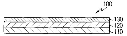
- FIG. 1 is a cross-sectional view of an electrode according to a preferred embodiment of the present invention.
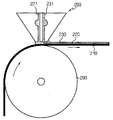
- FIG. 2 is a process diagram schematically illustrating a method of manufacturing an electrode according to an exemplary embodiment of the present invention.
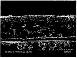
- Example 3 is an SEM photograph of the cross section of the electrode manufactured in Example 1;
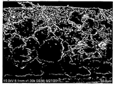
- FIG. 4 is an SEM photograph of the cross section of the electrode manufactured in Comparative Example 1.
- FIG. 1 is a schematic cross-sectional view of an electrode according to a preferred embodiment of the present invention.
- the configuration described in the embodiments and drawings described below are only the most preferred embodiment of the present invention and do not represent all of the technical idea of the present invention, which can be replaced at the time of the present application It should be understood that there may be various equivalents and variations.
- Electrode 100 of the present invention is a current collector (110); An electrode active material layer 120 formed on at least one surface of the current collector and including a mixture of electrode active material particles and a first binder polymer; And a porous coating layer 130 formed on a surface of the electrode active material layer, including a mixture of inorganic particles and a second binder polymer, and having a thickness variation satisfying Equation 1 below.
- T max is the maximum thickness of the porous coating layer formed on the surface of the electrode active material layer when the cross section of the porous coating layer is observed under an electron microscope
- T min is the minimum thickness of the porous coating layer
- T avg is the average thickness of the porous coating layer to be.
- the electrode active material layer of the electrode includes a mixture of electrode active material particles and a binder polymer. Since the size of the electrode active material particles is about 10 ⁇ m, the surface of the electrode active material layer is unevenly exposed because the electrode active material particles are exposed. do. When a slurry including a mixture of inorganic particles and a binder polymer on such a surface is applied to the surface of the electrode active material layer to form a porous coating layer, the dried porous coating layer is not uniformly formed, which may cause stability of the battery. have. Therefore, in order to stabilize the battery, the porous coating layer needs to be thickly formed. If the porous coating layer becomes thicker than a predetermined level, there is a problem in that the resistance increases.
- the inorganic particles and the second binder polymer penetrates into the electrode active material layer to block the pores of the electrode active material layer or resist resistance. It can increase the quality of the electrode.
- the electrode 100 of the present invention to apply a slurry of the mixture of the electrode active material particles and the first binder polymer for the formation of the electrode active material layer 120 on the surface of the current collector 110, and again the porous coating layer 130
- the slurry is dried at the same time. Since the porous coating layer 130 is first formed by the drying process, it is possible to prevent the penetration of the second binder polymer and the inorganic particles into the electrode active material layer 120 and at the same time form a uniform porous coating layer 130. have.
- the porous coating layer 130 thus formed has a thickness variation that satisfies Equation 1 below:
- T max is the maximum thickness of the porous coating layer formed on the surface of the electrode active material layer when the cross section of the porous coating layer is observed under an electron microscope
- T min is the minimum thickness of the porous coating layer
- T avg is the average thickness of the porous coating layer to be.
- the range of the thickness deviation can be measured by observing the electrode cross section with an electron microscope, and the thickness deviation can ensure the stability of the battery by having a constant thickness of the porous coating layer as an isolation layer, and a constant resistance in the coating layer plane direction. It means to have. Since the porous coating layer 130 of the present invention has an excellent thickness variation, the resistance variation of the isolation layer in the surface direction is excellent, and in order to secure stability of the secondary battery, the porous coating layer 130 does not need to be excessively thickened. This contributes to reducing the resistance of the electrode.
- the filling density of the electrode active material layer 120 of the present invention has a range of 3.0 to 3.9 g / cm 3 , or 3.2 to 3.7 g / cm 3 when the electrode is a positive electrode, 1.3 to 1.8 for the negative electrode to have a range of g / cm 3 range, or 1.4 to 1.7 g / cm 3 are preferred.
- the filling density is less than the above range, the contact between the active material and the conductive agent is insufficient to cause a current transfer to the current collector. If the filling density exceeds the above range, there is a problem in the delivery of the electrolyte due to the lack of voids in the active material.
- the packing density of the electrode active material layer is reduced by the applied solvent to reduce the quality of the electrode
- the particle size of the inorganic material applied during the second inorganic coating is smaller than the roughness of the electrode, the inorganic particles introduced into the secondary penetrate into the pores between the electrode active materials, thereby reducing the pores for delivery of the electrolyte solution in the electrode active material layer.
- negative electrode active material particles and positive electrode active material particles may be used according to the type of electrode.
- cathode active material particles are not particularly limited in kind, but may be LiCoO 2 , LiNiO 2 , LiMn 2 O 4 , LiCoPO 4 , LiFePO 4 , LiNiMnCoO 2, and LiNi 1-xyz Co x M1 y M2 z O 2 (M1 and M2 is any one selected from the group consisting of Al, Ni, Co, Fe, Mn, V, Cr, Ti, W, Ta, Mg and Mo independently of each other, x, y and z are independently of each other As an atomic fraction, 0 ⁇ x ⁇ 0.5, 0 ⁇ y ⁇ 0.5, 0 ⁇ z ⁇ 0.5, and x + y + z ⁇ 1).
- the type of negative electrode active material particles is not particularly limited, but natural graphite, artificial graphite, carbonaceous materials, LTO, silicon (Si
- the inorganic particles may be inorganic particles having a dielectric constant of 5 or more, inorganic particles having a lithium ion transfer ability, and the like.
- the inorganic particles having a dielectric constant of 5 or more are not particularly limited in kind, but BaTiO 3 , Pb (Zr x , Ti 1-x ) O 3 (PZT, 0 ⁇ x ⁇ 1), Pb 1-x La x Zr 1-y Ti y O 3 (PLZT), (1-x) Pb (Mg 1/3 Nb 2/3 ) O 3 -xPbTiO 3 (PMN-PT, 0 ⁇ x ⁇ 1), HfO 2 ), SrTiO 3 , SnO 2 , CeO 2 , MgO, NiO, CaO, ZnO, ZrO 2 , SiO 2 , Y 2 O 3 , Al 2 O 3 , SiC, TiO 2 , and the like.
- the inorganic particles having the lithium ion transport ability include lithium phosphate (Li 3 PO 4 ), lithium titanium phosphate (Li x Ti y (PO 4 ) 3 , 0 ⁇ x ⁇ 2, 0 ⁇ y ⁇ 3), lithium Aluminum titanium phosphate (Li x Al y Ti z (PO 4 ) 3 , 0 ⁇ x ⁇ 2, 0 ⁇ y ⁇ 1, 0 ⁇ z ⁇ 3), (LiAlTiP) x O y series glass (0 ⁇ x ⁇ 4, 0 ⁇ y ⁇ 13), lithium lanthanum titanate (Li x La y TiO 3, 0 ⁇ x ⁇ 2, 0 ⁇ y ⁇ 3), lithium germanium thiophosphate (Li x Ge y P z S w , 0 ⁇ x ⁇ 4, 0 ⁇ y ⁇ 1, 0 ⁇ z ⁇ 1, 0 ⁇ w ⁇ 5), Lithium Nitride (Li x N x N
- first binder polymer and the second binder polymer may be the same or different binder polymers, polyvinylidene fluoride-co-hexafluoropropylene, polyvinylidene fluoride- Trivinylidene fluoride-co-trichloroethylene, polymethylmethacrylate, polybutylacrylate, polyacrylonitrile, polyvinylpyrrolidone, polyvinylacetate polyvinylacetate, ethylene vinyl co-vinyl acetate, polyethylene oxide, polyarylate, cellulose acetate, cellulose acetate butyrate, cellulose acetate Propionate (cellulose acetate propionate, cyanoethylpullulan, cyanoethylpolyvinylalcohol, cyanoethylcellulose, cyanoethylsucrose, pullulan and carboxymethyl cellulose ( carboxyl methyl cellulose) and the like, but are not particularly limited thereto.
- binder polymers polyviny
- Electrode of the present invention can be prepared by forming a porous coating layer on the electrode active material layer, specific methods are as follows.
- electrode active material particles are dispersed, and the active material particle slurry in which the first binder polymer is dissolved in the first solvent is coated on at least one surface of the current collector (step S1).
- negative electrode active material particles and positive electrode active material particles may be used according to the type of electrode, and the above-mentioned negative electrode active material particles and positive electrode active material particles may be used.
- T g glass transition temperature
- the first binder polymer does not necessarily have an ion conductivity, but when using a polymer having ion conductivity, the performance of the electrochemical device may be further improved. Therefore, the first binder polymer is preferably as high as possible dielectric constant. As the specific first binder polymer, the above-mentioned binder polymer may be used.
- Non-limiting examples of the first solvent include acetone, tetrahydrofuran, methylene chloride, chloroform, dimethylformamide, N-methyl-2-pyrrolidone (N-methyl-2-pyrrolidone, NMP), cyclohexane, water or a mixture thereof can be used, and it is preferable to use a solvent which is easy to dry.
- An active material particle slurry in which electrode active material particles are dispersed and a first binder polymer is dissolved in a first solvent may be prepared by dissolving the first binder polymer in the first solvent and then adding and dispersing the active material particles. .
- the active material particles may be added in a state of being crushed to an appropriate size, but after the active material particles are added to the solution of the first binder polymer, the active material particles are preferably dispersed while being crushed using a ball mill method.
- the active material particle slurry may include a conductive material to improve ion conductivity of the active material particles.
- step S2 the inorganic particles are dispersed on the coated slurry of the active material particles, and the inorganic particle slurry in which the second binder polymer is dissolved in the second solvent is coated.
- the inorganic particles are not particularly limited as long as they are electrochemically stable. That is, the inorganic particles that can be used in the present invention are not particularly limited as long as the oxidation and / or reduction reactions do not occur in the operating voltage range (for example, 0 to 5 V on the basis of Li / Li + ) of the applied electrochemical device.
- the ionic conductivity of the electrolyte may be improved by contributing to an increase in the dissociation degree of the electrolyte salt, such as lithium salt, in the liquid electrolyte.
- Specific inorganic particles may use the above-mentioned inorganic particles.
- the average particle diameter of the inorganic particles is not particularly limited, but for forming a coating layer of uniform thickness and proper porosity, it is preferably in the range of 0.001 to 10 ⁇ m. When the thickness is less than 0.001 ⁇ m, the dispersibility may be decreased, and when the thickness is more than 10 ⁇ m, the thickness of the coating layer formed may be increased.
- the second binder polymer it is preferable to use a polymer having a glass transition temperature (T g ) of ⁇ 200 to 200 ° C., which may improve mechanical properties such as flexibility and elasticity of the finally formed coating layer. Because.
- T g glass transition temperature
- the second binder polymer does not necessarily have an ion conducting ability, but when a polymer having an ion conducting ability is used, the performance of the electrochemical device may be further improved. Therefore, the second binder polymer is preferably as high as possible dielectric constant.
- the dissociation degree of the salt in the electrolyte depends on the dielectric constant of the electrolyte solvent, the higher the dielectric constant of the second binder polymer, the higher the salt dissociation degree in the electrolyte.
- the second binder polymer may have a feature that can exhibit a high degree of swelling of the electrolyte by gelling when the liquid electrolyte is impregnated. Accordingly, it is preferred to use polymers having a solubility index of 15 to 45 MPa 1/2 , more preferred solubility indices in the range of 15 to 25 MPa 1/2 and 30 to 45 MPa 1/2 . Therefore, it is preferable to use hydrophilic polymers having more polar groups than hydrophobic polymers such as polyolefins. This is because when the solubility index is less than 15 MPa 1/2 and more than 45 MPa 1/2 , it is difficult to be swelled by a conventional battery liquid electrolyte. As a non-limiting example of such a second binder polymer, the above-mentioned binder polymer may be used.
- the weight ratio of the inorganic particles and the second binder polymer is preferably in the range of 50:50 to 99: 1, more preferably 70:30 to 95: 5.
- the content ratio of the inorganic particles to the second binder polymer is less than 50:50, the pore size and porosity of the coating layer formed by increasing the content of the polymer may be reduced.
- the content of the inorganic particles exceeds 99 parts by weight, the peeling resistance of the coating layer formed may be weakened because the content of the second binder polymer is small.
- a solubility index is similar to that of the second binder polymer to be used, and a boiling point is low. This is to facilitate uniform mixing and subsequent solvent removal.
- second solvents include acetone, tetrahydrofuran, methylene chloride, chloroform, dimethylformamide, N-methyl-2-pyrroli Toxin (N-methyl-2-pyrrolidone, NMP), cyclohexane, water or a mixture thereof.
- the slurry in which the inorganic particles are dispersed and the second binder polymer is dissolved in the second solvent may be prepared by dissolving the second binder polymer in the second solvent and then adding the inorganic particles and dispersing it.
- the inorganic particles may be added in the state of being crushed to an appropriate size, but after the inorganic particles are added to the solution of the second binder polymer, the inorganic particles are preferably dispersed while being crushed by using a ball mill method.
- the active material particle slurry coating step of (S1) and the inorganic particle slurry coating step of (S2) described above may be performed continuously or discontinuously using various methods such as slot die coating, slide coating, and curtain coating.
- the coating of the active material particles slurry of (S1) and the coating of the inorganic particles of (S2) are preferably performed continuously or simultaneously.
- a preferred example according to this embodiment is shown in FIG. 2.
- a multi-slot die 200 having two slots 221 and 231 is used to perform an active material particle slurry coating step of (S1) and an inorganic particle slurry coating step of (S2).
- the active material particle slurry 220 in which the active material particles are dispersed through the first slot 221 and the first binder polymer is dissolved in the first solvent is supplied.
- the inorganic particle slurry 230 is supplied through the second slot 231.
- the first solvent and the second solvent is dried at the same time, so that the porous coating layer is formed while the second solvent is dried first, so that the second binder polymer does not penetrate into the electrode active material layer, and then 1
- the solvent is dried to form an electrode active material layer (step S3).
- the reason why the first solvent and the second solvent present in the active material particle slurry and the inorganic particle slurry should be simultaneously dried is as follows.
- the second solvent in the inorganic particle slurry coated on the outermost part is dried before the first solvent. That is, when the second solvent in the inorganic particle slurry is dried, the inorganic particles are connected and fixed to each other by the second binder polymer, and pores are formed due to the interstitial volume between the inorganic particles. First is formed. Then, similar to the porous coating layer, the first solvent of the active material particle slurry is dried to form pores while the active material particles are connected and fixed to each other by the first binder polymer to form the electrode active material layer.
- the active material particle slurry coating layer in which the first binder polymer is dissolved in the first solvent is first dried to form an electrode active material layer, and then the inorganic particle slurry is applied, the second binder solution and the inorganic particles form the electrode active material.
- the penetration into the pores of the layer lowers the porosity, thereby increasing the resistance and degrading the quality of the electrode.
- the size of the electrode active material particles is approximately 10 ⁇ m or less, the surface of the electrode active material layer is rugged because the electrode active material particles are exposed.
- the size of the inorganic particles is only a few tens of nm, when the inorganic particle slurry is applied on the surface of the electrode active material layer to form a porous coating layer, the dried porous coating layer is not uniformly formed Stability can be a problem.
- a nonuniform porous coating layer may be formed by holes or bubbles generated on the surface while the slurry of the inorganic particles penetrates into the pores of the electrode active material layer.
- the inorganic particle slurry by applying a solvent to the surface of the electrode active material layer in advance, in this case, it is possible to improve the uniformity of the porous coating layer ,
- the electrode active material layer absorbs the solvent may cause a problem that the packing density is lowered.
- the present invention is an electrochemical device comprising an anode, a cathode, and an electrolyte, wherein the anode, the cathode or the positive electrode is an electrode having a porous coating layer of inorganic particles and a second binder polymer that can replace the separator on the electrode surface
- An electrochemical device is provided.
- the electrochemical device includes all devices that undergo an electrochemical reaction, and specific examples thereof include all kinds of primary, secondary cells, fuel cells, solar cells, or capacitors.
- the electrochemical device may be manufactured by selectively interposing a separator between the anode and the cathode.
- Electrolyte that may be used in the electrochemical device of the present invention is A + B - A salt of the structure, such as, A + comprises a Li +, Na +, an alkali metal cation or an ion composed of a combination thereof, such as K + B - it is PF 6 -, BF 4 -, Cl -, Br -, I -, ClO 4 -, AsF 6 -, CH 3 CO 2 -, CF 3 SO 3 -, N (CF 3 SO 2) 2 -, C Salts containing ions consisting of anions such as (CF 2 SO 2 ) 3 - or a combination thereof are propylene carbonate (PC), ethylene carbonate (EC), diethyl carbonate (DEC), dimethyl carbonate (DMC), dipropyl Carbonate (DPC), dimethylsulfoxide, acetonitrile, dimethoxyethane, diethoxyethane, tetrahydrofuran, N-methyl-2-pyrrolidone
- the electrolyte injection may be performed at an appropriate stage of the battery manufacturing process, depending on the manufacturing process and the required physical properties of the final product. That is, it may be applied before the battery assembly or at the end of battery assembly.
- An aqueous negative electrode active material slurry was prepared by mixing graphite as a super-P as a conductive agent.
- inorganic particles were prepared by mixing alumina (Al 2 O 3 ) and barium titanate (BaTiO 3 ) at 9: 1, and styrene butadiene rubber (SBR) and carboxymethyl cellulose (CMC) at 2: 1.
- the second binder polymer was prepared by mixing, and the inorganic particle slurry was prepared by dispersing the prepared inorganic particles in an aqueous solution in which the prepared second binder polymer was dissolved in water as a second solvent.
- a negative electrode active material particle slurry is supplied as a lower layer of the multilayer slot die coater based on a current collector made of copper, and an inorganic particle slurry is supplied as an upper layer to simultaneously form a double coating layer, and the double coating layer is simultaneously dried.
- the upper layer of the inorganic particle slurry After drying from the outside (that is, the upper layer of the inorganic particle slurry), it was pressed through a roll press. The cross section of the sample obtained through the process was observed by SEM to confirm that the negative electrode active material layer and the porous coating layer were clearly separated and formed as shown in FIG. 3 .
- Comparative Example 1 An electrode coated with an inorganic particle slurry after formation of the electrode active material layer and dried
- the negative electrode active material particle slurry was first coated on a current collector made of copper to form an electrode active material layer. After filling the pores of the negative electrode active material layer using ethanol as a solvent in the secondary coating, the inorganic particle slurry was applied before drying, dried at the same time, and then pressed through a roll press. The cross section of the sample obtained through the process was observed by SEM to confirm that the inorganic particles penetrated into the space between the particles of the negative electrode active material.
- Example 1 only the negative electrode active material slurry was applied to the lower layer, and the packing density was measured using the electrode weight and thickness of the specimen without applying the inorganic particle slurry on the upper layer, followed by applying the inorganic particle slurry to the upper layer. Filling density was measured using the electrode weight and thickness of the prepared specimen.
- Example 1 Comparative Example 1 When coating single layer 1.52 g / cm 3 1.53 g / cm 3 When multilayer coating 1.50 g / cm 3 1.34 g / cm 3
Abstract
La présente invention concerne une électrode comprenant une couche de revêtement poreux ayant une variation d'épaisseur représentée par la formule 1 ci-dessous, et un procédé de fabrication de celle-ci, l'électrode comprenant : un collecteur ; une couche de matériau actif d'électrode formée sur au moins une surface du collecteur, et comprenant une composition consistant en des particules de matériau actif d'électrode et un premier polymère liant ; et une composition consistant en des particules inorganiques et un second polymère liant, qui est formée sur la surface de la couche de matériau actif d'électrode. [Formule 1] : (Tmax-Tmin)/Tavg ≤ 0,35. Dans la formule 1, lorsque les sections de la couche de revêtement poreux sont observées en utilisant un microscope électronique, Tmax est l'épaisseur maximale de la couche de revêtement poreux formée sur la surface de la couche de matériau actif d'électrode, Tmin est l'épaisseur minimale de la couche de revêtement poreux, et Tavg est l'épaisseur moyenne de la couche de revêtement. La présente invention permet la fabrication d'une électrode en utilisant un procédé de séchage simultané de la couche de matériau actif d'électrode et de la couche de revêtement poreux, et évite que le polymère liant de la couche de revêtement poreux ne s'infiltre dans la couche de matériau actif d'électrode, de façon à fournir une excellente qualité à l'électrode. En outre, la formation uniforme de la couche de revêtement poreux contribue à la stabilité d'une batterie.
Priority Applications (5)
| Application Number | Priority Date | Filing Date | Title |
|---|---|---|---|
| CN201280045623.XA CN103828092B (zh) | 2012-04-10 | 2012-12-24 | 具有多孔涂层的电极、其制造方法和包括其的电化学器件 |
| EP12873884.6A EP2838140B8 (fr) | 2012-04-10 | 2012-12-24 | Electrode comprenant une couche de revêtement poreuse, procédé de fabrication de celle-ci et dispositif électrochimique |
| PL12873884T PL2838140T3 (pl) | 2012-04-10 | 2012-12-24 | Elektroda z porowatą warstwą powlekającą, sposób jej wytwarzania i urządzenie elektrochemiczne |
| JP2014510268A JP5847299B2 (ja) | 2012-04-10 | 2012-12-24 | 多孔性コーティング層を含む電極、前記電極の製造方法、及び前記電極を含む電気化学素子 |
| US13/965,413 US8951669B2 (en) | 2012-04-10 | 2013-08-13 | Electrode having porous coating layer, manufacturing method thereof and electrochemical device containing the same |
Applications Claiming Priority (2)
| Application Number | Priority Date | Filing Date | Title |
|---|---|---|---|
| KR20120037356A KR101511732B1 (ko) | 2012-04-10 | 2012-04-10 | 다공성 코팅층이 형성된 전극, 이의 제조방법 및 이를 포함하는 전기화학소자 |
| KR10-2012-0037356 | 2012-04-10 |
Related Child Applications (1)
| Application Number | Title | Priority Date | Filing Date |
|---|---|---|---|
| US13/965,413 Continuation US8951669B2 (en) | 2012-04-10 | 2013-08-13 | Electrode having porous coating layer, manufacturing method thereof and electrochemical device containing the same |
Publications (1)
| Publication Number | Publication Date |
|---|---|
| WO2013154253A1 true WO2013154253A1 (fr) | 2013-10-17 |
Family
ID=49327789
Family Applications (1)
| Application Number | Title | Priority Date | Filing Date |
|---|---|---|---|
| PCT/KR2012/011377 WO2013154253A1 (fr) | 2012-04-10 | 2012-12-24 | Electrode comprenant une couche de revêtement poreux, procédé de fabrication de celle-ci, et dispositif électrochimique la comprenant |
Country Status (7)
| Country | Link |
|---|---|
| US (1) | US8951669B2 (fr) |
| EP (1) | EP2838140B8 (fr) |
| JP (2) | JP5847299B2 (fr) |
| KR (1) | KR101511732B1 (fr) |
| CN (1) | CN103828092B (fr) |
| PL (1) | PL2838140T3 (fr) |
| WO (1) | WO2013154253A1 (fr) |
Cited By (3)
| Publication number | Priority date | Publication date | Assignee | Title |
|---|---|---|---|---|
| CN105814711A (zh) * | 2014-04-01 | 2016-07-27 | 株式会社Lg化学 | 隔膜的制造方法、由该方法制造的隔膜以及包含隔膜的电化学装置 |
| CN107681113A (zh) * | 2016-08-01 | 2018-02-09 | 宁德时代新能源科技股份有限公司 | 正极片及其制备方法以及二次电池 |
| CN110364662A (zh) * | 2018-04-11 | 2019-10-22 | 宁德新能源科技有限公司 | 隔离膜和电化学装置 |
Families Citing this family (35)
| Publication number | Priority date | Publication date | Assignee | Title |
|---|---|---|---|---|
| KR20150106810A (ko) | 2013-11-21 | 2015-09-22 | 삼성에스디아이 주식회사 | 분리막 및 이를 이용한 이차 전지 |
| WO2015076571A1 (fr) * | 2013-11-21 | 2015-05-28 | 삼성에스디아이 주식회사 | Composition d'agent de revêtement de séparateur, séparateur formé de la composition d'agent de revêtement, et batterie faisant appel à celui-ci |
| WO2015102139A1 (fr) * | 2014-01-06 | 2015-07-09 | 주식회사 엘지화학 | Électrode négative pour batterie secondaire et batterie secondaire au lithium comprenant celle-ci |
| JP6098852B2 (ja) | 2014-01-06 | 2017-03-22 | エルジー・ケム・リミテッド | 二次電池用負極及びこれを含むリチウム二次電池 |
| KR101788232B1 (ko) * | 2014-10-06 | 2017-10-19 | 주식회사 엘지화학 | 접착력이 개선된 리튬 이차전지용 전극 |
| US11322745B2 (en) * | 2014-10-15 | 2022-05-03 | Semiconductor Energy Laboratory Co., Ltd. | Electrode, power storage device, electronic device, and manufacturing method of electrode |
| KR101765381B1 (ko) * | 2015-01-28 | 2017-08-07 | 주식회사 엘지화학 | 전극의 이중 코팅 방법 |
| CN104766946B (zh) * | 2015-04-13 | 2017-03-29 | 湖南杉杉新能源有限公司 | 锂离子电池正极极片及其制备方法和锂离子电池 |
| JP6699351B2 (ja) * | 2016-05-25 | 2020-05-27 | 日本電気株式会社 | 電極の製造方法および電極の検査方法 |
| KR102040257B1 (ko) * | 2016-09-13 | 2019-11-04 | 주식회사 엘지화학 | 전극의 제조방법 |
| CN108666525A (zh) * | 2017-04-01 | 2018-10-16 | 宁德时代新能源科技股份有限公司 | 一种负极极片,其制备方法及二次电池 |
| US10038193B1 (en) | 2017-07-28 | 2018-07-31 | EnPower, Inc. | Electrode having an interphase structure |
| US11081731B2 (en) * | 2017-10-18 | 2021-08-03 | International Business Machines Corporation | High-capacity rechargeable batteries |
| CN111386616B (zh) | 2017-11-24 | 2023-06-02 | 日本电气株式会社 | 制造二次电池用电极的方法和制造二次电池的方法 |
| US20210036330A1 (en) * | 2018-03-12 | 2021-02-04 | Nec Corporation | Electrode for secondary battery, secondary battery using the electrode and method for manufacturing thereof |
| KR102195725B1 (ko) * | 2018-03-15 | 2020-12-28 | 삼성에스디아이 주식회사 | 리튬 이차전지용 양극, 이의 제조방법 및 이를 포함한 리튬 이차전지 |
| KR20210045625A (ko) * | 2019-10-17 | 2021-04-27 | 주식회사 엘지화학 | 활물질 이중층을 형성하는 전극 슬러리 코팅 장치 및 방법 |
| PL3751641T3 (pl) | 2018-10-02 | 2022-03-28 | Lg Chem, Ltd. | Wielowarstwowa anoda zawierająca związek na bazie krzemu i zawierająca ją litowa bateria akumulatorowa |
| KR20200038168A (ko) | 2018-10-02 | 2020-04-10 | 주식회사 엘지화학 | 실리콘계 화합물을 포함하는 다층 구조 음극 및 이를 포함하는 리튬 이차전지 |
| KR102421618B1 (ko) * | 2019-03-25 | 2022-07-14 | 주식회사 엘지에너지솔루션 | 전기화학소자용 세퍼레이터의 제조방법 |
| US11569550B2 (en) | 2019-04-05 | 2023-01-31 | EnPower, Inc. | Electrode with integrated ceramic separator |
| JP7131472B2 (ja) * | 2019-04-25 | 2022-09-06 | トヨタ自動車株式会社 | セパレータ付き電極板の製造方法及び電池の製造方法 |
| CN110943215B (zh) | 2019-05-31 | 2020-12-04 | 宁德时代新能源科技股份有限公司 | 锂离子二次电池 |
| CN111180737B (zh) | 2019-05-31 | 2021-08-03 | 宁德时代新能源科技股份有限公司 | 锂离子二次电池、电芯及负极极片 |
| WO2021033689A1 (fr) * | 2019-08-19 | 2021-02-25 | 富士フイルム株式会社 | Procédé de production de corps d'électrode moulé |
| KR20210043146A (ko) * | 2019-10-11 | 2021-04-21 | 삼성전기주식회사 | 이차 전지 |
| US10998553B1 (en) * | 2019-10-31 | 2021-05-04 | EnPower, Inc. | Electrochemical cell with integrated ceramic separator |
| WO2021181603A1 (fr) * | 2020-03-12 | 2021-09-16 | 本田技研工業株式会社 | Électrode de batterie secondaire au lithium-ion, batterie secondaire au lithium-ion et procédé de fabrication pour électrode de batterie secondaire au lithium-ion |
| KR102581119B1 (ko) * | 2020-06-16 | 2023-09-20 | 고려대학교 세종산학협력단 | 인화게르마늄 나노시트 및 이의 제조방법 |
| KR20220001142A (ko) | 2020-06-29 | 2022-01-05 | 주식회사 유뱃 | 전기화학소자용 복합전극 및 이의 제조방법 |
| CN113394367A (zh) * | 2021-06-15 | 2021-09-14 | 湖北亿纬动力有限公司 | 一种浆料涂布方法及极片 |
| US11594784B2 (en) | 2021-07-28 | 2023-02-28 | EnPower, Inc. | Integrated fibrous separator |
| CN113796866B (zh) * | 2021-08-10 | 2023-06-20 | 中山大学 | 一种电极及其制备方法和应用 |
| WO2024036852A1 (fr) * | 2022-08-19 | 2024-02-22 | Techtronic Cordless Gp | Batterie lithium-ion avec revêtement céramique d'électrode |
| CN117578034B (zh) * | 2024-01-15 | 2024-04-16 | 宁德新能源科技有限公司 | 隔膜、以及包含其的电化学装置及电子装置 |
Citations (6)
| Publication number | Priority date | Publication date | Assignee | Title |
|---|---|---|---|---|
| JP2005353584A (ja) * | 2004-05-14 | 2005-12-22 | Matsushita Electric Ind Co Ltd | リチウムイオン二次電池とその製造法 |
| KR20070092621A (ko) * | 2006-03-10 | 2007-09-13 | 주식회사 엘지화학 | 다공성 활성층이 코팅된 전극, 그 제조방법 및 이를 구비한전기화학소자 |
| JP2007273123A (ja) * | 2006-03-30 | 2007-10-18 | Matsushita Electric Ind Co Ltd | 非水電解質二次電池とその製造方法 |
| JP2008179903A (ja) * | 2007-01-23 | 2008-08-07 | Hitachi Maxell Ltd | 多孔質膜、電気化学素子用セパレータ、多孔質膜の製造方法、非水電解質電池および非水電解質電池の製造方法 |
| KR20080109237A (ko) | 2007-06-12 | 2008-12-17 | 삼성에스디아이 주식회사 | 세라믹 세퍼레이터 형성방법 |
| JP2009193906A (ja) * | 2008-02-18 | 2009-08-27 | Panasonic Corp | 電池用電極板の耐熱層の塗布重量測定方法、製造方法および製造装置 |
Family Cites Families (14)
| Publication number | Priority date | Publication date | Assignee | Title |
|---|---|---|---|---|
| JP3622383B2 (ja) * | 1995-12-11 | 2005-02-23 | 宇部興産株式会社 | 電極シートの製造方法 |
| US5834052A (en) * | 1995-12-11 | 1998-11-10 | Fuji Photo Film Co., Ltd. | Producing electrode sheet with multilayer structure by simultaneous multilayer coating |
| JP4602254B2 (ja) * | 2003-09-18 | 2010-12-22 | パナソニック株式会社 | リチウムイオン二次電池 |
| KR100666821B1 (ko) * | 2004-02-07 | 2007-01-09 | 주식회사 엘지화학 | 유/무기 복합 다공성 코팅층이 형성된 전극 및 이를포함하는 전기 화학 소자 |
| CN100394632C (zh) * | 2004-03-30 | 2008-06-11 | 松下电器产业株式会社 | 非水电解液二次电池 |
| EP1746675B1 (fr) | 2004-05-14 | 2013-01-02 | Panasonic Corporation | Batterie secondaire ionique au lithium et procede de fabrication de ladite batterie |
| JP2006324020A (ja) * | 2005-05-17 | 2006-11-30 | Mitsui Mining & Smelting Co Ltd | 非水電解液二次電池の製造方法 |
| JP5241120B2 (ja) * | 2006-03-17 | 2013-07-17 | 三洋電機株式会社 | 非水電解質電池 |
| KR100947181B1 (ko) * | 2007-11-19 | 2010-03-15 | 주식회사 엘지화학 | 다공성 코팅층이 형성된 세퍼레이터 및 이를 구비한전기화학소자 |
| WO2009078159A1 (fr) * | 2007-12-14 | 2009-06-25 | Panasonic Corporation | Batterie secondaire à électrolyte non aqueux et procédé de fabrication associé |
| KR100983161B1 (ko) * | 2008-01-11 | 2010-09-20 | 삼성에스디아이 주식회사 | 전극조립체 및 이를 구비한 이차전지 |
| KR101664502B1 (ko) * | 2008-03-31 | 2016-10-11 | 제온 코포레이션 | 다공막 및 2 차 전지 전극 |
| JP5428296B2 (ja) * | 2008-11-04 | 2014-02-26 | コニカミノルタ株式会社 | 二次電池、その製造方法、及びラミネート型二次電池 |
| KR101198806B1 (ko) * | 2010-12-06 | 2012-11-07 | 현대자동차주식회사 | 다공절연층을 포함하는 이차전지 전극 및 그 제조 방법 |
-
2012
- 2012-04-10 KR KR20120037356A patent/KR101511732B1/ko active IP Right Grant
- 2012-12-24 EP EP12873884.6A patent/EP2838140B8/fr active Active
- 2012-12-24 JP JP2014510268A patent/JP5847299B2/ja active Active
- 2012-12-24 WO PCT/KR2012/011377 patent/WO2013154253A1/fr active Application Filing
- 2012-12-24 PL PL12873884T patent/PL2838140T3/pl unknown
- 2012-12-24 CN CN201280045623.XA patent/CN103828092B/zh active Active
-
2013
- 2013-08-13 US US13/965,413 patent/US8951669B2/en active Active
-
2015
- 2015-08-28 JP JP2015168576A patent/JP6430346B2/ja active Active
Patent Citations (6)
| Publication number | Priority date | Publication date | Assignee | Title |
|---|---|---|---|---|
| JP2005353584A (ja) * | 2004-05-14 | 2005-12-22 | Matsushita Electric Ind Co Ltd | リチウムイオン二次電池とその製造法 |
| KR20070092621A (ko) * | 2006-03-10 | 2007-09-13 | 주식회사 엘지화학 | 다공성 활성층이 코팅된 전극, 그 제조방법 및 이를 구비한전기화학소자 |
| JP2007273123A (ja) * | 2006-03-30 | 2007-10-18 | Matsushita Electric Ind Co Ltd | 非水電解質二次電池とその製造方法 |
| JP2008179903A (ja) * | 2007-01-23 | 2008-08-07 | Hitachi Maxell Ltd | 多孔質膜、電気化学素子用セパレータ、多孔質膜の製造方法、非水電解質電池および非水電解質電池の製造方法 |
| KR20080109237A (ko) | 2007-06-12 | 2008-12-17 | 삼성에스디아이 주식회사 | 세라믹 세퍼레이터 형성방법 |
| JP2009193906A (ja) * | 2008-02-18 | 2009-08-27 | Panasonic Corp | 電池用電極板の耐熱層の塗布重量測定方法、製造方法および製造装置 |
Cited By (6)
| Publication number | Priority date | Publication date | Assignee | Title |
|---|---|---|---|---|
| CN105814711A (zh) * | 2014-04-01 | 2016-07-27 | 株式会社Lg化学 | 隔膜的制造方法、由该方法制造的隔膜以及包含隔膜的电化学装置 |
| CN105814711B (zh) * | 2014-04-01 | 2018-09-11 | 株式会社Lg化学 | 隔膜的制造方法、由该方法制造的隔膜以及包含隔膜的电化学装置 |
| CN107681113A (zh) * | 2016-08-01 | 2018-02-09 | 宁德时代新能源科技股份有限公司 | 正极片及其制备方法以及二次电池 |
| CN107681113B (zh) * | 2016-08-01 | 2020-07-28 | 宁德时代新能源科技股份有限公司 | 正极片及其制备方法以及二次电池 |
| CN110364662A (zh) * | 2018-04-11 | 2019-10-22 | 宁德新能源科技有限公司 | 隔离膜和电化学装置 |
| CN110364662B (zh) * | 2018-04-11 | 2022-07-05 | 宁德新能源科技有限公司 | 隔离膜和电化学装置 |
Also Published As
| Publication number | Publication date |
|---|---|
| CN103828092B (zh) | 2016-07-06 |
| EP2838140A4 (fr) | 2015-09-09 |
| JP2014522549A (ja) | 2014-09-04 |
| US20140023921A1 (en) | 2014-01-23 |
| JP6430346B2 (ja) | 2018-11-28 |
| JP2016042467A (ja) | 2016-03-31 |
| KR101511732B1 (ko) | 2015-04-13 |
| EP2838140B1 (fr) | 2019-06-26 |
| KR20130114926A (ko) | 2013-10-21 |
| PL2838140T3 (pl) | 2019-12-31 |
| EP2838140A1 (fr) | 2015-02-18 |
| CN103828092A (zh) | 2014-05-28 |
| JP5847299B2 (ja) | 2016-01-20 |
| EP2838140B8 (fr) | 2019-08-07 |
| US8951669B2 (en) | 2015-02-10 |
Similar Documents
| Publication | Publication Date | Title |
|---|---|---|
| WO2013154253A1 (fr) | Electrode comprenant une couche de revêtement poreux, procédé de fabrication de celle-ci, et dispositif électrochimique la comprenant | |
| WO2013012292A9 (fr) | Séparateur, procédé pour le fabriquer et dispositif électrochimique l'utilisant | |
| WO2013058421A1 (fr) | Procédé de fabrication d'un séparateur, séparateur formé par ledit procédé et dispositif électrochimique présentant ledit séparateur | |
| WO2012046966A2 (fr) | Dispositif électrochimique à caractéristiques de cycle améliorées | |
| WO2011105866A2 (fr) | Procédé de fabrication d'un séparateur, séparateur fabriqué à partir de ce procédé et procédé de fabrication d'un dispositif électrochimique comprenant ledit séparateur | |
| WO2010117195A2 (fr) | Séparateur à couche de revêtement poreuse, procédé de fabrication, et dispositif électrochimique ainsi équipé | |
| WO2011065765A2 (fr) | Procédé pour fabriquer un séparateur, séparateur fabriqué selon celui-ci, et dispositif électrochimique comprenant le séparateur | |
| WO2010024559A2 (fr) | Séparateur pourvu d'une couche de revêtement poreux, procédé de fabrication de ce séparateur et dispositif électrochimique pourvu de ce séparateur | |
| WO2011040704A2 (fr) | Procédé de fabrication de séparateur, séparateur ainsi fabriqué et procédé de fabrication de dispositif électrochimique comportant le séparateur | |
| WO2017010780A1 (fr) | Séparateur et dispositif électrochimique le comprenant | |
| WO2014073937A1 (fr) | Procédé de fabrication de séparateur, séparateur fabriqué ainsi et dispositif électrochimique le comprenant | |
| WO2010076989A2 (fr) | Séparateur doté d'une couche de revêtement poreuse, et dispositif électrochimique le comprenant | |
| WO2011105865A2 (fr) | Procédé de fabrication d'un séparateur, séparateur fabriqué à partir de ce procédé et procédé de fabrication d'un dispositif électrochimique comprenant ledit séparateur | |
| WO2014182095A1 (fr) | Structure-électrode recouverte d'une couche d'isolant, son procédé de fabrication, et élément électrochimique contenant la structure-électrode | |
| WO2013070031A1 (fr) | Séparateur et dispositif électrochimique comprenant ledit séparateur | |
| WO2011019187A2 (fr) | Batterie secondaire au lithium | |
| WO2011062460A2 (fr) | Procédé de préparation de séparateur comportant une couche poreuse de revêtement, séparateur formé à partir de cette couche et dispositif électrochimique la contenant | |
| WO2014084681A1 (fr) | Membrane de séparation de batterie secondaire contenant des couches de revêtement à double porosité en particules inorganiques ayant différentes propriétés de surface, batterie secondaire l'intégrant et procédé de fabrication d'une membrane de séparation | |
| WO2014088270A1 (fr) | Matériau actif d'anode à haute capacité pour batterie secondaire au lithium, procédé de fabrication associé, et batterie secondaire au lithium comprenant ledit matériau actif d'anode à haute capacité | |
| WO2012150838A2 (fr) | Séparateur comprenant une couche de revêtement poreuse et dispositif électrochimique comprenant celui-ci | |
| WO2012165758A1 (fr) | Batterie secondaire au lithium | |
| WO2013157902A1 (fr) | Procédé de fabrication de séparateur, séparateur formé ainsi, et dispositif électrochimique comprenant ledit séparateur | |
| WO2013066052A1 (fr) | Séparateur et dispositif électrochimique le comportant | |
| WO2010027203A2 (fr) | Séparateur présentant une couche de revêtement poreuse et dispositif électrochimique comprenant ce séparateur | |
| WO2013165151A1 (fr) | Séparateur et dispositif électrochimique le comprenant |
Legal Events
| Date | Code | Title | Description |
|---|---|---|---|
| WWE | Wipo information: entry into national phase |
Ref document number: 2012873884 Country of ref document: EP |
|
| ENP | Entry into the national phase |
Ref document number: 2014510268 Country of ref document: JP Kind code of ref document: A |
|
| 121 | Ep: the epo has been informed by wipo that ep was designated in this application |
Ref document number: 12873884 Country of ref document: EP Kind code of ref document: A1 |
|
| NENP | Non-entry into the national phase |
Ref country code: DE |