WO2013153760A1 - Wireless power transfer system, wireless power transfer apparatus, wireless power transfer method, control method for the wireless power transfer apparatus, and storage medium storing program - Google Patents
Wireless power transfer system, wireless power transfer apparatus, wireless power transfer method, control method for the wireless power transfer apparatus, and storage medium storing program Download PDFInfo
- Publication number
- WO2013153760A1 WO2013153760A1 PCT/JP2013/002164 JP2013002164W WO2013153760A1 WO 2013153760 A1 WO2013153760 A1 WO 2013153760A1 JP 2013002164 W JP2013002164 W JP 2013002164W WO 2013153760 A1 WO2013153760 A1 WO 2013153760A1
- Authority
- WO
- WIPO (PCT)
- Prior art keywords
- power transfer
- power
- elements
- wireless power
- power transmission
- Prior art date
Links
- 238000012546 transfer Methods 0.000 title claims abstract description 182
- 238000000034 method Methods 0.000 title claims description 14
- 230000005540 biological transmission Effects 0.000 claims abstract description 205
- 238000004891 communication Methods 0.000 claims description 62
- 230000006870 function Effects 0.000 description 9
- 238000012545 processing Methods 0.000 description 7
- 238000005516 engineering process Methods 0.000 description 6
- 239000003990 capacitor Substances 0.000 description 3
- 230000008859 change Effects 0.000 description 3
- 230000008878 coupling Effects 0.000 description 2
- 238000010168 coupling process Methods 0.000 description 2
- 238000005859 coupling reaction Methods 0.000 description 2
- 238000001514 detection method Methods 0.000 description 2
- 238000010586 diagram Methods 0.000 description 2
- 238000005259 measurement Methods 0.000 description 2
- 230000008569 process Effects 0.000 description 2
- 230000008901 benefit Effects 0.000 description 1
- 238000006073 displacement reaction Methods 0.000 description 1
- 230000005684 electric field Effects 0.000 description 1
- 230000005674 electromagnetic induction Effects 0.000 description 1
- 238000009434 installation Methods 0.000 description 1
- PWPJGUXAGUPAHP-UHFFFAOYSA-N lufenuron Chemical compound C1=C(Cl)C(OC(F)(F)C(C(F)(F)F)F)=CC(Cl)=C1NC(=O)NC(=O)C1=C(F)C=CC=C1F PWPJGUXAGUPAHP-UHFFFAOYSA-N 0.000 description 1
- 238000012986 modification Methods 0.000 description 1
- 230000004048 modification Effects 0.000 description 1
- 230000003287 optical effect Effects 0.000 description 1
- 230000004044 response Effects 0.000 description 1
- 238000004804 winding Methods 0.000 description 1
Images


Classifications
-
- H—ELECTRICITY
- H04—ELECTRIC COMMUNICATION TECHNIQUE
- H04B—TRANSMISSION
- H04B5/00—Near-field transmission systems, e.g. inductive or capacitive transmission systems
- H04B5/70—Near-field transmission systems, e.g. inductive or capacitive transmission systems specially adapted for specific purposes
- H04B5/79—Near-field transmission systems, e.g. inductive or capacitive transmission systems specially adapted for specific purposes for data transfer in combination with power transfer
-
- H—ELECTRICITY
- H01—ELECTRIC ELEMENTS
- H01F—MAGNETS; INDUCTANCES; TRANSFORMERS; SELECTION OF MATERIALS FOR THEIR MAGNETIC PROPERTIES
- H01F38/00—Adaptations of transformers or inductances for specific applications or functions
- H01F38/14—Inductive couplings
-
- H—ELECTRICITY
- H02—GENERATION; CONVERSION OR DISTRIBUTION OF ELECTRIC POWER
- H02J—CIRCUIT ARRANGEMENTS OR SYSTEMS FOR SUPPLYING OR DISTRIBUTING ELECTRIC POWER; SYSTEMS FOR STORING ELECTRIC ENERGY
- H02J50/00—Circuit arrangements or systems for wireless supply or distribution of electric power
- H02J50/10—Circuit arrangements or systems for wireless supply or distribution of electric power using inductive coupling
- H02J50/12—Circuit arrangements or systems for wireless supply or distribution of electric power using inductive coupling of the resonant type
-
- H—ELECTRICITY
- H02—GENERATION; CONVERSION OR DISTRIBUTION OF ELECTRIC POWER
- H02J—CIRCUIT ARRANGEMENTS OR SYSTEMS FOR SUPPLYING OR DISTRIBUTING ELECTRIC POWER; SYSTEMS FOR STORING ELECTRIC ENERGY
- H02J50/00—Circuit arrangements or systems for wireless supply or distribution of electric power
- H02J50/40—Circuit arrangements or systems for wireless supply or distribution of electric power using two or more transmitting or receiving devices
- H02J50/402—Circuit arrangements or systems for wireless supply or distribution of electric power using two or more transmitting or receiving devices the two or more transmitting or the two or more receiving devices being integrated in the same unit, e.g. power mats with several coils or antennas with several sub-antennas
-
- H—ELECTRICITY
- H02—GENERATION; CONVERSION OR DISTRIBUTION OF ELECTRIC POWER
- H02J—CIRCUIT ARRANGEMENTS OR SYSTEMS FOR SUPPLYING OR DISTRIBUTING ELECTRIC POWER; SYSTEMS FOR STORING ELECTRIC ENERGY
- H02J50/00—Circuit arrangements or systems for wireless supply or distribution of electric power
- H02J50/80—Circuit arrangements or systems for wireless supply or distribution of electric power involving the exchange of data, concerning supply or distribution of electric power, between transmitting devices and receiving devices
-
- H—ELECTRICITY
- H02—GENERATION; CONVERSION OR DISTRIBUTION OF ELECTRIC POWER
- H02J—CIRCUIT ARRANGEMENTS OR SYSTEMS FOR SUPPLYING OR DISTRIBUTING ELECTRIC POWER; SYSTEMS FOR STORING ELECTRIC ENERGY
- H02J50/00—Circuit arrangements or systems for wireless supply or distribution of electric power
- H02J50/90—Circuit arrangements or systems for wireless supply or distribution of electric power involving detection or optimisation of position, e.g. alignment
-
- H—ELECTRICITY
- H04—ELECTRIC COMMUNICATION TECHNIQUE
- H04B—TRANSMISSION
- H04B5/00—Near-field transmission systems, e.g. inductive or capacitive transmission systems
- H04B5/20—Near-field transmission systems, e.g. inductive or capacitive transmission systems characterised by the transmission technique; characterised by the transmission medium
- H04B5/24—Inductive coupling
- H04B5/26—Inductive coupling using coils
Definitions
- the present invention relates to wireless power transfer.
- a wireless power transfer system including a power transmission apparatus that transmits power in a wireless (non-contact) manner without a connection by a connector and a power reception apparatus that charges a mounted battery by using the power supplied from the power transmission apparatus.
- a technology of changing load resistances of a power transmission element and a power reception element, a power transmission voltage, a coil structure, or a coupling degree between coils and determining whether the efficiency before the change is improved after the change is proposed as a technology of increasing a power transfer efficiency (PTL 1).
- a technology is also proposed in which plural matching circuit units forming a wanted resonance frequency on a power transmission side are provided, and plural resonance points are realized without provision of plural power transmission coils so that power transmission and reception efficiencies are increased in accordance with resonance points on a power reception side (PTL 2).
- a difference in the power transfer efficiency is generated because of each of combinations of plural power transmission coils having different sizes and shapes and having different sizes and shapes of power reception coils.
- a size of the power reception coil installed inside the apparatus is also restricted depending on the size of the apparatus and the product itself, and sizes of the respective power reception coils may be different from each other.
- the plural power reception apparatuses including the above-described power reception coils having the different sizes and shapes are charged by using a single power transmission apparatus, a problem occurs that the power transmission may efficiently be conducted for a certain apparatus, but the power transmission is not efficiently conducted for the other apparatus.
- sizes of the power transmission apparatuses vary from one another.
- the sizes of the power transmission coils are different from each other in accordance with the power transmission apparatuses, and even in a case where a single power reception apparatus is charged, a difference in the power transfer efficiency may be generated depending on the sizes and shapes of the power transmission coils.
- the technologies proposed in PTL 1 and PTL 2 are technologies of improving a decrease in the power transfer efficiency which is caused by a distance between the power transmission and reception coils, a location relationship, or a deviation of resonance points.
- the decrease in the power transfer efficiency caused by the combinations of the sizes and shapes of each of the power transmission and reception coils is however not taken into account in the proposed technologies.
- the present invention relates to a wireless power transfer system composed of a power transmission apparatus including power transmission elements configured to transmit power and a power reception apparatus including power reception elements configured to receive the power.
- the wireless power transfer system communicates information related to the power transmission elements or the power reception elements between the power transmission apparatus and the power reception apparatus and selects a combination of the power transmission element and the power reception element used for wireless power transfer among plural combinations of the power transmission elements and the power reception elements by using the communicated information.
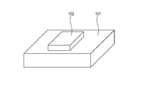
- Fig. 1 illustrates a configuration of a wireless power transfer system according to an embodiment.
- Fig. 2A illustrates a configuration of a power transmission apparatus.
- Fig. 2B illustrates a configuration of the power transmission apparatus.
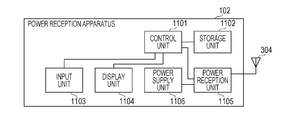
- Fig. 3A illustrates a configuration of a power reception apparatus.
- Fig. 3B illustrates a configuration of the power reception apparatus.
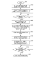
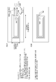
- Fig. 4 is a flow chart illustrating an operation by the power transmission apparatus.
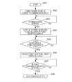
- Fig. 5 is a flow chart illustrating an operation by the power reception apparatus.
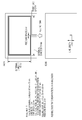
- Fig. 6 illustrates a transfer efficiency of each of plural combinations of power transmission elements and power reception elements.
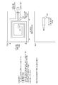
- Fig. 7 illustrates an example of the power transmission element.
- Fig. 8 illustrates an example of the power transmission element.
- Fig. 9 illustrates an example of the power reception element.
- Fig. 10 illustrates an example of the power reception element.
- Fig. 11 illustrates an example of the power transmission element.
- Fig. 12 illustrates an example of
- a wireless power transfer system including a power transmission apparatus that transmits power and a power reception apparatus that receives the power according to the present embodiment will be described.
- Information related to the power transmission elements or the power reception elements is communicated between the power transmission apparatus and the power reception apparatus, and a combination of the power transmission element and the power reception element having satisfactory power transmission and reception efficiencies is selected according to the present embodiment.
- a configuration of the wireless power transfer system according to the present embodiment will be described by using Fig. 1.
- a power transmission apparatus 101 is composed of a wireless power transfer apparatus
- a power reception apparatus 102 is composed of a wireless power transfer apparatus.
- a wireless power system according to the present embodiment supplies power from the power transmission apparatus 101 to the power reception apparatus 102 on the basis of a magnetic field resonance system.
- the magnetic field resonance system is a system in which the power is transferred through coupling based on resonance (electric resonance) between a resonator (resonance element) provided in the power transmission apparatus 101 and a resonator (resonance element) provided in the power reception apparatus 102.
- the description will be made by using the wireless power transfer system using the magnetic field resonance system as an example according to the present embodiment, but the wireless power transfer system (non-contact power transfer system) is not limited to the above.
- a power transfer system utilizing electromagnetic induction, electric field resonance, microwaves, laser (light), or the like may also be used.
- the power transmission apparatus 101 includes plural power transmission elements (power transmission coils) having mutually different sizes and shapes. Examples of the power transmission elements will be illustrated in Figs. 7, 8, 11, and 12.
- the power reception apparatus 102 is installed at a location on the power transmission apparatus 101 where power transmission can be conducted to charge a power supply unit of the power reception apparatus 102 by using the power wirelessly transferred from the power transmission apparatus 101.
- FIG. 2A illustrates a configuration of an entirety of the power transmission apparatus 101.
- a control unit 1001 is configured to control the entire apparatus by executing a control program stored in a storage unit 1002.
- the storage unit 1002 stores the control program executed by the control unit 1001 and various pieces of information. Various operations which will be described below are carried out while the control program stored in the storage unit 1002 is executed by the control unit 1001.
- An input unit 1003 is used for a user to perform various inputs.
- a display unit 1004 performs various displays and has a function of outputting information that can visually be recognized like an LCD or an LED or a function of outputting sound like a speaker.
- a power transmission unit 1005 transmits power to the power reception apparatus 102.
- the power transmission unit 1005 communicates with the power reception apparatus 102.
- Fig. 2B is an explanatory diagram for describing the power transmission unit 1005 in detail.
- a power transmission control unit 201 controls power transmission.
- a first switching unit 202 switches a connection of the power transmission control unit 201 to a first matching circuit unit 203 or a second matching circuit unit 209.
- the first matching circuit unit 203 is composed of an inductor, a capacitor, or the like.
- the first matching circuit unit 203 is a circuit constituting a resonance circuit having a predetermined resonance frequency by being connected to a first power transmission element 206.
- the predetermined resonance frequency according to the present embodiment is set as 13.56 MHz.
- a first communication circuit unit 204 is configured to perform a wireless communication by using radio waves transmitted and received by the first power transmission element 206.
- a second switching unit 205 switches a connection of the first power transmission element 206 to the first matching circuit unit 203 or the first communication circuit unit 204.
- the second switching unit 205 may set the first power transmission element 206 in an electrically open or short-circuited state.
- the first power transmission element 206 is a power transfer element for transferring the power.
- the first power transmission element 206 is composed of a coil.
- a wireless communication control unit 207 is a chip designed to wirelessly communication with another apparatus.
- a third switching unit 208 switches a connection of the wireless communication control unit 207 to the second matching circuit unit 209 or a second communication circuit unit 210.
- the second matching circuit unit 209 is composed of an inductor, a capacitor, or the like.
- the second matching circuit unit 209 is a circuit constituting a resonance circuit having a predetermined resonance frequency by being connected to a second power transmission element 212.
- the predetermined resonance frequency according to the present embodiment is set as 13.56 MHz.
- the second communication circuit unit 210 is configured to perform a wireless communication by using radio waves transmitted and received by the second power transmission element 212.
- a fourth switching unit 211 switches a connection of the second power transmission element 212 to the second matching circuit unit 209 or the second communication circuit unit 210.
- the fourth switching unit 211 may set the second power transmission element 212 in an open or short-circuited state.
- the second power transmission element 212 is a power transfer element for transferring the power.
- the second power transmission element 212 is composed of a coil.
- the first switching unit 202, the second switching unit 205, the third switching unit 208, and the fourth switching unit 211 switch the presence or absence of the physical connections of the respective elements but may be composed of units configured to avoid electric connections of the respective elements by using a rectifier such as, for example, a diode.
- Fig. 3A and Fig. 3B illustrate a hardware configuration of the power reception apparatus 102.
- Fig. 3A illustrates a configuration of the entire apparatus.
- the power reception apparatus 102 corresponds to the entire apparatus.
- a control unit 1101 controls the entire apparatus by executing a control program stored in a storage unit 1102.
- the storage unit 1102 stores the control program executed by the control unit 1101 and various pieces of information. The various operations are carried out while the control program stored in the storage unit 1102 is executed by the control unit 1101.
- An input unit 1103 is used for the user to perform various inputs.
- a display unit 1104 performs various displays and has a function of outputting information that can visually be recognized like an LCD or an LED or a function of outputting sound like a speaker.
- a power reception unit 1105 charges a power supply unit 1106 by using the power wirelessly transmitted from the power transmission apparatus 101.
- the power reception unit 1105 performs a communication with the power transmission apparatus 101.
- Fig. 3B is an explanatory diagram for describing the power reception unit 1105 in detail.
- Fig. 3B illustrates a block configuration of the power reception unit 1105.
- a power reception control unit 301 controls power reception.
- a matching circuit unit 302 is composed of an inductor, a capacitor, or the like.
- the matching circuit unit 302 is a circuit constituting a resonance circuit having a predetermined resonance frequency by being connected to a power reception element 304.
- the predetermined resonance frequency according to the present embodiment is set as 13.56 MHz.
- a switching unit 303 is designed to switch a connection of the power reception element 304 to the matching circuit unit 302 or a communication circuit unit 306.
- the power reception element is a power transfer element for transferring the power.
- the power reception element 304 is composed of a coil.
- a wireless communication control unit 305 is a chip designed to wirelessly communication with another apparatus.
- the communication circuit unit 306 is configured to conduct a wireless communication by using radio waves transmitted and received by the power reception unit 1105.
- the switching unit 303 switches the presence or absence of the physical connections of the respective elements but may be composed of a unit configured to avoid electric connections of the respective elements by using a rectifier such as, for example, a diode.
- NFC Near field communication
- the wireless power transfer is conducted in a same frequency band as a frequency band used for the NFC communication. Therefore, a power transmission element used for the wireless power transfer may be used as an antenna used for the NFC communication.
- a difference in the transfer efficiency depending on combinations of the sizes and shapes of the antennas on the transmission side and the reception side is relatively small.
- a difference in the transfer efficiency depending on combinations of the sizes and shapes of the power transmission elements and power reception elements in the wireless power transfer is relatively large. The communication may satisfactorily be conducted even in a case where the same element is used, but a problem may occur that the transfer efficiency is degraded in the wireless power transfer.
- Fig. 6 also illustrates a transfer efficiency at the time of conducting the wireless power transfer in each of the combinations.
- the respective elements are represented by a vertical and horizontal size, and a transfer efficiency at a time when the power transmission element and the power reception element are combined with each other is indicated by dB.
- the transfer efficiency takes a minus value while the transfer efficiency is higher as the value is closer to 0 dB.
- Fig. 7, Fig. 8, Fig. 11, and Fig. 12 illustrate examples of the power transmission element.
- Fig. 9, Fig. 10, and Fig. 13 illustrate examples of the power reception element.
- the measurement on the transfer efficiency is conducted while each of the power transmission elements and the power reception elements is connected to a matching circuit to resonate at a resonance frequency of 13.56 MHz.
- the wireless power transfer is conducted by using the power transmission element at 10 cm * 10 cm illustrated in Fig. 8 with respect to each of the power reception elements illustrated in Fig. 9, Fig. 10, and Fig. 13.
- the power transmission is conducted at a relatively satisfactory transfer efficiency of -0.26 dB with respect to the power reception element illustrated in Fig. 9.
- the power transmission is conducted at a dissatisfactory transfer efficiency of -5 dB or lower with respect to the power reception elements illustrated in Fig. 10 and Fig. 13.
- the wireless power transfer is conducted by using the power transmission element at 35 mm * 55 mm illustrated in Fig. 11 with respect to the power reception element illustrated in Fig.
- the transfer efficiency is improved to -0.9 dB as compared with the case of using the power transmission element illustrated in Fig. 8.
- the difference in the transfer efficiency is generated in this manner depending on the combinations of the sizes and shapes of the respective power transmission and reception elements.
- the wireless power transfer is conducted by using a combination of power transmission and reception elements having a satisfactory transfer efficiency on the basis of the sizes and shapes of the respective power transmission and reception elements.
- FIG. 4 A specific operation by the wireless power system according to the present embodiment will be described by using flow charts illustrated in Fig. 4 and Fig. 5.
- the following processing is realized while control programs stored in respective apparatuses are executed by a control unit to control computation and process on information and respective pieces of hardware.
- the control unit executes the programs, and a part or all of function configurations realized through the computation and process on the information or the like may be realized by the hardware in the following flow chart.
- An operation by the power transmission apparatus 101 will be described by using a flow chart illustrated in Fig. 4.
- An operation by the power reception apparatus 102 will be described by using a flow chart illustrated in Fig. 5.
- the power transmission apparatus 101 starts the operation (S401)
- one of the plural power transmission elements for establishing a communication with another apparatus is selected.
- the NFC communication is conducted, for example, by the first power transmission element 206 (S402)
- the second switching unit 205 connects the first power transmission element 206 to the first communication circuit unit 204.
- the third switching unit 208 establishes a connection between the first communication circuit unit 204 and the wireless communication control unit 207 (S403).
- the switching unit 303 connects the power reception element 304 to the communication circuit unit 306 to perform a communication (S502).
- the power transmission apparatus 101 and the power reception apparatus 102 are approximated to each other by a user. It is subsequently determined whether or not the communication is started in accordance with the mutual detection of the presence of the other apparatus within a communicable range by the power transmission apparatus 101 and the power reception apparatus 102 (S404), (S503).
- the power reception apparatus 102 notifies the power transmission apparatus 101 of information on the size or the shape of at least the power reception element 304 (S504).
- the information related to the element size herein may include an area, a structure, an external diameter, an outer circumference, and a winding number of the coil of the element, and the like.
- Information related to these shapes and information related to the size in accordance with the shape may be communication between the power transmission apparatus 101 and the power reception apparatus 102.
- the information related to the size in accordance with the shape may be, for example, information on a radius, a diameter, a circumference, and the like when the power transfer element has a circular shape.
- the power transmission apparatus 101 that obtains the information on the power reception element 304 (S405) selects the power transmission element corresponding to the size and the shape of the power reception element 304 (S406).
- a table indicating the transfer efficiencies between the power transmission elements illustrated in Fig. 6 may be held at this time and used when the selection is made.
- a consideration will be given of a case, for example, in which the first power transmission element 206 has a size of 45 mm * 65 mm illustrated in Fig. 12, the second power transmission element 212 has a size of 9 cm * 12 cm illustrated in Fig. 7, and the power reception element 304 has a size of 47 mm * 78 mm.
- the power transmission apparatus 101 selects the second power transmission element 212 at 12 cm * 9 cm which has the better transfer efficiency than the other power transmission element for the power transmission element used for the power transmission on the basis of the table illustrated in Fig. 6.
- the power transmission apparatus 101 selects the first power transmission element 206 at 45 mm * 65 mm from Fig. 6 for the power transmission element used for the power transmission.
- the power transmission apparatus 101 may calculate an area ratio of each of the plural power transmission elements to the power reception element on the basis of the information related to the area of the power reception element obtained from the power reception apparatus 102 through the communication and select the power transmission element on the basis of the area ratio for the power transmission element used for the power transmission.
- the power transmission apparatus 101 When the selection of the power transmission element is ended, the power transmission apparatus 101 notifies the power reception apparatus 102 of a message indicating a start of the power transmission (S407).
- the power transmission apparatus 101 conducts matching circuit switching (S408).
- the second switching unit 205 In the power transmission apparatus 101, in a case where the first power transmission element 206 is selected, the second switching unit 205 connects the first power transmission element 206 to the first matching circuit unit 203. This is because the communication circuit unit 306 or the wireless communication control unit 305 is protected since the power of the radio waves used for the power transfer is larger than the power of the radio waves used for the NFC communication so that the communication circuit unit 306 or the wireless communication control unit 305 may be damaged by the power of the radio waves used for the power transfer. Therefore, when the power transfer is conducted, the communication circuit unit 306 is not electrically connected to the wireless communication control unit 305.
- the first switching unit 202 connects the first matching circuit unit 203 to a power transmission unit.
- the power transmission apparatus 101 sets the second power transmission element 212 that is not selected by the fourth switching unit 211 as an open or short-circuit state. This is because, if the power transmission element that is not selected remains being connected to one of the matching circuits, a circuit characteristic of the selected power transmission element is changed. This change may cause a decrease in the transfer efficiency.
- the state of the power transmission element that is not selected may be switched into the open or short-circuit state depending on whether the NFC communication is conducted or the wireless power transfer is conducted.
- the fourth switching unit 211 connects the second power transmission element 212 to the second matching circuit unit 209.
- the third switching unit 208 connects the second matching circuit unit 209 to the power transmission unit.
- the second switching unit 205 sets the first power transmission element 206 as an open or short-circuit state.
- the power transmission apparatus 101 subsequently performs processing for alignment in accordance with the selected power transmission element (S409) to suppress the decrease in the transfer efficiency caused by a displacement between the power transmission element and the power reception element.
- the power transmission apparatus 101 presents an installation location of the power reception apparatus 102 to the user, for example, in accordance with the selected power transmission element via the display unit 1004.
- a display for urging the user to move the power reception apparatus 102 is also conducted. If the power transmission apparatus 101 may move the selected power transmission element by using a motor or the like, processing of moving the selected power transmission element to the power transmission location where the power reception apparatus 102 is installed is conducted.
- the power transmission control unit 201 subsequently detects the power reception apparatus 102 (S410). When the power reception apparatus 102 is detected, a power transmission sequence is started (S411).
- the power reception apparatus 102 After the notification to the power reception element, in response to the notification of the power transmission start (S505), the power reception apparatus 102 performs the matching circuit switching (S506).
- the switching unit 303 is controlled, and the power reception element 304 is connected to the matching circuit unit 302. This is because if the power transmission is started while the power reception element 304 remains to be connected to the communication circuit unit 306, the communication circuit unit 306 and the wireless communication control unit 305 may not normally operate because of the transmitted power. Therefore, when the power transfer is conducted, the power reception element 304 is not connected to the communication circuit unit 306.
- the power reception apparatus 102 starts to receive the power transmitted from the power transmission apparatus 101 (S508).
- the power transmission apparatus 101 selects the power transmission element having the highest efficiency among the plural power transmission elements having the mutually different sizes or shapes on the basis of the information related to the size and the shape of the power reception element notified from the power reception apparatus 102, so that it is possible to conduct the power transmission to the power reception apparatus 102.
- the power transmission apparatus 101 selects the power transmission element used for the power transmission, but the power reception apparatus 102 may select the power transmission element of the power transmission apparatus 101 and instruct the power transmission apparatus 101 on the power transmission element used for the power transmission.
- the power transmission apparatus 101 instead of the obtainment of the information related to the size and the shape of the power reception element, the power transmission apparatus 101 notifies the power reception apparatus 102 of all pieces of information related to the sizes of the plural power transmission elements by using the wireless communication control unit 305.
- the power reception apparatus 102 selects the power transmission element preferably used with its own power reception element among power transmission elements on the basis of the obtained information related to the sizes and shapes of the power transmission elements.
- a method of selecting the power transmission element is similar to the case in which the power transmission element is selected on the side of the power transmission apparatus 101.
- the power reception apparatus 102 subsequently notifies the power transmission apparatus 101 of information related to the selected power transmission element by the wireless communication control unit 305.
- the power transmission apparatus 101 selects the power reception apparatus 102 and connects the instructed power transmission element to the power transmission unit to carry out the power transmission.
- the power reception apparatus 102 may include plural power reception elements having different sizes and shapes and select the power reception used for the power reception on the basis of the information related to the sizes and shapes of the power transmission elements from the power transmission apparatus 101.
- the embodiment of the present invention may also be applied to a case in which the power transmission apparatus 101 includes plural power transmission elements having different sizes and shapes and the power reception apparatus 102 includes plural power reception elements having different sizes and shapes.
- at least one of the power transmission apparatus 101 and the power reception apparatus 102 communicates the information related to the sizes of the elements and selects a combination of the power transmission element and the power reception element used for the power transmission and reception as a system.
- a communication circuit may regularly be connected to an element for the communication.
- the power transmission apparatus 101 superimposes a control signal on the transmitted power, and a load modulation is conducted on the received power on the side of the power reception apparatus 102 to perform the communication with the power transmission apparatus 101 in the wireless power transfer, only the first switching unit 202 is used, and other switching units are not used.
- the wireless power transfer may be conducted with the combination of the power transmission element or the power reception element having the satisfactory transfer efficiency on the basis of the information related to the size and the shape. Even in a case where the communication based on the NFC communication and the element used for the wireless power transfer are commonly be used, the communication may satisfactorily be conducted, and also the problem of the decrease in the transfer efficiency may be suppressed in the wireless power transfer.
- the configuration has been described in which the information related to the power transfer element is communicated, and the element used for the wireless power transfer is selected among the plural wireless power transfer elements on the basis of the communicated content.
- a communication on the information related to the power transfer system may be conducted with another apparatus, and the element used for the wireless power transfer may be selected among the plural wireless power transfer elements on the basis of the power transfer system dealt with by the other apparatus.
- the wireless power transfer may be started by using the element selected in S406 or the like, and in a case where the efficiency of the wireless power transfer is below a predetermined value, the element may be selected again.
- a wireless power transfer apparatus including at least three or more power transfer elements may select two or more elements among the three or more power transfer elements to perform the wireless power transfer by using information communicated with another wireless power transfer apparatus.
- the information communicated with the other wireless power transfer apparatus in this case may include information related to the power transfer element and information related to a location.
- Embodiments of the present invention can also be realized by executing the following processing. That is, the processing includes supplying software (program) that realizes the functions of the above-described embodiments to a system or an apparatus via a network or various storage media and causing a computer (or a CPU or an MPU) of the system or the apparatus to read out and execute the program.
- software program
- the processing includes supplying software (program) that realizes the functions of the above-described embodiments to a system or an apparatus via a network or various storage media and causing a computer (or a CPU or an MPU) of the system or the apparatus to read out and execute the program.
- Embodiments of the present invention can also be realized by a computer of a system or apparatus that reads out and executes computer executable instructions recorded on a storage medium (e.g., non-transitory computer-readable storage medium) to perform the functions of one or more of the above-described embodiment(s) of the present invention, and by a method performed by the computer of the system or apparatus by, for example, reading out and executing the computer executable instructions from the storage medium to perform the functions of one or more of the above-described embodiment(s).
- the computer may comprise one or more of a central processing unit (CPU), micro processing unit (MPU), or other circuitry, and may include a network of separate computers or separate computer processors.
- the computer executable instructions may be provided to the computer, for example, from a network or the storage medium.
- the storage medium may include, for example, one or more of a hard disk, a random-access memory (RAM), a read only memory (ROM), a storage of distributed computing systems, an optical disk (such as a compact disc (CD), digital versatile disc (DVD), or Blu-ray Disc (BD) TM ), a flash memory device, a memory card, and the like.
Landscapes
- Engineering & Computer Science (AREA)
- Power Engineering (AREA)
- Computer Networks & Wireless Communication (AREA)
- Signal Processing (AREA)
- Near-Field Transmission Systems (AREA)
- Charge And Discharge Circuits For Batteries Or The Like (AREA)
Priority Applications (1)
| Application Number | Priority Date | Filing Date | Title |
|---|---|---|---|
| US14/394,008 US20150061401A1 (en) | 2012-04-13 | 2013-03-29 | Wireless power transfer system, wireless power transfer apparatus, wireless power transfer method, control method for the wireless power transfer apparatus, and storage medium storing program |
Applications Claiming Priority (2)
| Application Number | Priority Date | Filing Date | Title |
|---|---|---|---|
| JP2012-092216 | 2012-04-13 | ||
| JP2012092216A JP5885570B2 (ja) | 2012-04-13 | 2012-04-13 | 無線電力伝送システム、無線電力伝送装置、無線電力伝送方法、無線電力伝送装置の制御方法、プログラム。 |
Publications (1)
| Publication Number | Publication Date |
|---|---|
| WO2013153760A1 true WO2013153760A1 (en) | 2013-10-17 |
Family
ID=49327347
Family Applications (1)
| Application Number | Title | Priority Date | Filing Date |
|---|---|---|---|
| PCT/JP2013/002164 WO2013153760A1 (en) | 2012-04-13 | 2013-03-29 | Wireless power transfer system, wireless power transfer apparatus, wireless power transfer method, control method for the wireless power transfer apparatus, and storage medium storing program |
Country Status (3)
| Country | Link |
|---|---|
| US (1) | US20150061401A1 (ja) |
| JP (2) | JP5885570B2 (ja) |
| WO (1) | WO2013153760A1 (ja) |
Families Citing this family (15)
| Publication number | Priority date | Publication date | Assignee | Title |
|---|---|---|---|---|
| JP5211256B1 (ja) * | 2011-12-22 | 2013-06-12 | Necトーキン株式会社 | 電子機器及びシステム |
| JP6108915B2 (ja) * | 2013-04-02 | 2017-04-05 | キヤノン株式会社 | 受電装置、その制御方法およびプログラム |
| KR102113853B1 (ko) * | 2013-07-17 | 2020-06-03 | 삼성전자주식회사 | 커플링 영역 검출 방법 및 장치 |
| JP6141175B2 (ja) * | 2013-11-12 | 2017-06-07 | 京セラ株式会社 | 電子機器 |
| JP6406167B2 (ja) * | 2015-08-18 | 2018-10-17 | 株式会社デンソー | パッチアレイアンテナおよび送電システム |
| JP6641889B2 (ja) | 2015-10-30 | 2020-02-05 | セイコーエプソン株式会社 | 液体吐出装置及び液体吐出システム |
| JP6641886B2 (ja) * | 2015-10-30 | 2020-02-05 | セイコーエプソン株式会社 | 液体吐出装置及び液体吐出システム |
| JP6641888B2 (ja) | 2015-10-30 | 2020-02-05 | セイコーエプソン株式会社 | 液体吐出装置及び液体吐出システム |
| JP6641887B2 (ja) | 2015-10-30 | 2020-02-05 | セイコーエプソン株式会社 | 液体吐出装置及び液体吐出システム |
| KR102495243B1 (ko) | 2018-08-23 | 2023-02-03 | 삼성전자주식회사 | 외부 전자 장치로부터 수신된 식별 정보에 기반하여 안테나와 연결된 스위치를 선택적으로 개방하거나 또는 연결하는 전자 장치 및 방법 |
| JP7108181B2 (ja) * | 2018-09-19 | 2022-07-28 | 株式会社村田製作所 | 無線電力伝送システム |
| JP7259275B2 (ja) * | 2018-11-13 | 2023-04-18 | 三菱電機株式会社 | フェイズドアレイアンテナ装置、電力伝送システム、ビームパターン形成方法及び電力伝送方法 |
| JP7377129B2 (ja) | 2020-02-21 | 2023-11-09 | 株式会社ダイセル | 連結構造、エアバッグ装置、及び車両用シート |
| JP7018981B2 (ja) * | 2020-02-28 | 2022-02-14 | ソフトバンク株式会社 | システム、管理装置、及びプログラム |
| WO2022130483A1 (ja) * | 2020-12-15 | 2022-06-23 | 日本電信電話株式会社 | 光給電システム、光給電方法及び受電光通信装置 |
Citations (6)
| Publication number | Priority date | Publication date | Assignee | Title |
|---|---|---|---|---|
| JPH10233235A (ja) * | 1997-02-20 | 1998-09-02 | Fujitsu Ltd | 複数の機器に対応した非接触型充電装置 |
| JP2010200594A (ja) * | 2009-01-27 | 2010-09-09 | Panasonic Electric Works Co Ltd | 非接触電力伝送システム |
| JP2010220284A (ja) * | 2009-03-13 | 2010-09-30 | Mitsubishi Electric Corp | 非接触受給電装置、受電装置及び給電装置 |
| JP2011004474A (ja) * | 2009-06-16 | 2011-01-06 | Sanyo Electric Co Ltd | 充電台 |
| JP2011125138A (ja) * | 2009-12-10 | 2011-06-23 | Canon Inc | 電子機器 |
| JP2012033740A (ja) * | 2010-07-30 | 2012-02-16 | Sumida Corporation | コイル |
Family Cites Families (26)
| Publication number | Priority date | Publication date | Assignee | Title |
|---|---|---|---|---|
| JP4128170B2 (ja) * | 2004-11-02 | 2008-07-30 | シャープ株式会社 | 電力供給システム及びこれを用いた電力供給サービス |
| US8169185B2 (en) * | 2006-01-31 | 2012-05-01 | Mojo Mobility, Inc. | System and method for inductive charging of portable devices |
| JP2009081943A (ja) * | 2007-09-26 | 2009-04-16 | Seiko Epson Corp | 送電制御装置、送電装置、送電側装置および無接点電力伝送システム |
| JP4600454B2 (ja) * | 2007-09-26 | 2010-12-15 | セイコーエプソン株式会社 | 送電制御装置、送電装置、無接点電力伝送システム、2次コイルの位置決め方法 |
| JP4600453B2 (ja) * | 2007-09-26 | 2010-12-15 | セイコーエプソン株式会社 | 送電制御装置、送電装置、受電装置、無接点電力伝送システム、電子機器、2次コイル位置検出方法および1次コイルの位置決め方法 |
| CA2711489A1 (en) * | 2008-01-07 | 2009-07-16 | David W. Baarman | Inductive power supply with duty cycle control |
| WO2009114671A1 (en) * | 2008-03-13 | 2009-09-17 | Access Business Group International Llc | Inductive power supply system with multiple coil primary |
| US9130395B2 (en) * | 2008-12-12 | 2015-09-08 | Hanrim Postech Co., Ltd. | Non-contact charging station with planar spiral power transmission coil and method for controlling the same |
| TWI380628B (en) * | 2009-02-26 | 2012-12-21 | Darfon Electronics Corp | Power managing method and power managing circuit and energy transferring system using thereof |
| JP5481091B2 (ja) * | 2009-04-14 | 2014-04-23 | 富士通テン株式会社 | 無線電力伝送装置および無線電力伝送方法 |
| JP5496553B2 (ja) * | 2009-06-15 | 2014-05-21 | 三洋電機株式会社 | 充電台 |
| US8558411B2 (en) * | 2009-07-24 | 2013-10-15 | Access Business Group International Llc | Power supply |
| CN101635468B (zh) * | 2009-09-01 | 2015-04-01 | 北京中星微电子有限公司 | 无触点充电设备及其充电方法、充电电池和充电器 |
| US9027840B2 (en) * | 2010-04-08 | 2015-05-12 | Access Business Group International Llc | Point of sale inductive systems and methods |
| WO2011128969A1 (ja) * | 2010-04-13 | 2011-10-20 | 富士通株式会社 | 電力供給システム、送電器、および受電器 |
| JP2011229314A (ja) * | 2010-04-21 | 2011-11-10 | Sanyo Electric Co Ltd | 充電装置、および、充電装置の制御方法 |
| JP5476211B2 (ja) * | 2010-05-19 | 2014-04-23 | Necトーキン株式会社 | 送電装置、受電装置および非接触電力伝送及び通信システム |
| JP5539069B2 (ja) * | 2010-06-30 | 2014-07-02 | キヤノン株式会社 | 給電装置 |
| JP2012034524A (ja) * | 2010-08-02 | 2012-02-16 | Panasonic Corp | 無線電力伝送装置 |
| JP2012070557A (ja) * | 2010-09-24 | 2012-04-05 | Panasonic Electric Works Co Ltd | 非接触式電力伝送用のコイルモジュールおよびこれを具備する電池パック |
| US10079090B2 (en) * | 2010-12-01 | 2018-09-18 | Triune Systems, LLC | Multiple coil data transmission system |
| KR101688948B1 (ko) * | 2011-05-27 | 2016-12-22 | 엘지전자 주식회사 | 무선 전력 전송을 이용한 데이터 통신 연결 수립 |
| US9054547B2 (en) * | 2011-09-06 | 2015-06-09 | Samsung Electronics Co., Ltd | Communication method and apparatus in wireless recharging system |
| KR101305303B1 (ko) * | 2011-09-21 | 2013-09-06 | 주식회사 한림포스텍 | 무선 전력전송장치 및 방법 |
| US9236756B2 (en) * | 2011-12-05 | 2016-01-12 | Qualcomm Incorporated | Apparatus for wireless device charging using radio frequency (RF) energy and device to be wirelessly charged |
| US20140266018A1 (en) * | 2013-03-12 | 2014-09-18 | Qualcomm Incorporated | Systems and methods for extending the power capability of a wireless charger |
-
2012
- 2012-04-13 JP JP2012092216A patent/JP5885570B2/ja active Active
-
2013
- 2013-03-29 WO PCT/JP2013/002164 patent/WO2013153760A1/en active Application Filing
- 2013-03-29 US US14/394,008 patent/US20150061401A1/en not_active Abandoned
-
2016
- 2016-02-08 JP JP2016022056A patent/JP6147377B2/ja active Active
Patent Citations (6)
| Publication number | Priority date | Publication date | Assignee | Title |
|---|---|---|---|---|
| JPH10233235A (ja) * | 1997-02-20 | 1998-09-02 | Fujitsu Ltd | 複数の機器に対応した非接触型充電装置 |
| JP2010200594A (ja) * | 2009-01-27 | 2010-09-09 | Panasonic Electric Works Co Ltd | 非接触電力伝送システム |
| JP2010220284A (ja) * | 2009-03-13 | 2010-09-30 | Mitsubishi Electric Corp | 非接触受給電装置、受電装置及び給電装置 |
| JP2011004474A (ja) * | 2009-06-16 | 2011-01-06 | Sanyo Electric Co Ltd | 充電台 |
| JP2011125138A (ja) * | 2009-12-10 | 2011-06-23 | Canon Inc | 電子機器 |
| JP2012033740A (ja) * | 2010-07-30 | 2012-02-16 | Sumida Corporation | コイル |
Also Published As
| Publication number | Publication date |
|---|---|
| JP5885570B2 (ja) | 2016-03-15 |
| JP2016123266A (ja) | 2016-07-07 |
| JP6147377B2 (ja) | 2017-06-14 |
| JP2013223300A (ja) | 2013-10-28 |
| US20150061401A1 (en) | 2015-03-05 |
Similar Documents
| Publication | Publication Date | Title |
|---|---|---|
| WO2013153760A1 (en) | Wireless power transfer system, wireless power transfer apparatus, wireless power transfer method, control method for the wireless power transfer apparatus, and storage medium storing program | |
| KR101558698B1 (ko) | 스마트키의 위치에 따른 무선 충전 제어방법 | |
| JP6032900B2 (ja) | 電子機器 | |
| JP2009201328A (ja) | 充電装置及び充電システム | |
| JP6643041B2 (ja) | 送電装置 | |
| US20130328407A1 (en) | Wireless power transmission apparatus, wireless power transmission system, and wireless communication apparatus | |
| JP6494227B2 (ja) | 給電装置、制御方法およびプログラム | |
| JP2014128149A (ja) | 給電装置、制御方法及びコンピュータプログラム | |
| KR102450421B1 (ko) | 무선 통신 시스템에서 빔포밍을 수행하는 전자 장치 및 이를 위한 방법 | |
| JP2015233393A (ja) | 電子機器 | |
| JP2016100922A (ja) | 送電装置、送電装置の制御方法、プログラム | |
| WO2021161776A1 (ja) | 受電装置および送電装置、ならびにそれらの制御方法およびプログラム | |
| JP2015233392A (ja) | 電子機器 | |
| US10027156B2 (en) | Electronic apparatus and charging method | |
| US20160372976A1 (en) | Power transmitting apparatus, power receiving apparatus, control methods therefor, and computer-readable storage medium | |
| JP2015008620A (ja) | 無線電力伝送装置、無線電力伝送装置の制御方法、プログラム | |
| US9853500B2 (en) | Power supply apparatus, method, and recording medium | |
| JP2017099239A (ja) | 送電装置 | |
| JP6700856B2 (ja) | 給電装置、受電装置およびそれらの制御方法、プログラム | |
| US10079516B2 (en) | Power transmission apparatus, method for controlling the same, and program | |
| JP6525730B2 (ja) | 移動体端末および無接点充電器 | |
| WO2015198568A1 (en) | Power transmission apparatus, control method for power transmission apparatus, and program | |
| JP6743579B2 (ja) | 受電装置 | |
| JP2019033598A (ja) | 非接触給電装置 | |
| JP6222986B2 (ja) | 電子機器、制御方法、プログラム及び記録媒体 |
Legal Events
| Date | Code | Title | Description |
|---|---|---|---|
| 121 | Ep: the epo has been informed by wipo that ep was designated in this application |
Ref document number: 13775366 Country of ref document: EP Kind code of ref document: A1 |
|
| WWE | Wipo information: entry into national phase |
Ref document number: 14394008 Country of ref document: US |
|
| NENP | Non-entry into the national phase |
Ref country code: DE |
|
| 122 | Ep: pct application non-entry in european phase |
Ref document number: 13775366 Country of ref document: EP Kind code of ref document: A1 |