WO2013147106A1 - 成形金型及びレンズの製造方法 - Google Patents
成形金型及びレンズの製造方法 Download PDFInfo
- Publication number
- WO2013147106A1 WO2013147106A1 PCT/JP2013/059421 JP2013059421W WO2013147106A1 WO 2013147106 A1 WO2013147106 A1 WO 2013147106A1 JP 2013059421 W JP2013059421 W JP 2013059421W WO 2013147106 A1 WO2013147106 A1 WO 2013147106A1
- Authority
- WO
- WIPO (PCT)
- Prior art keywords
- lens
- mold
- transfer surface
- molding
- molding die
- Prior art date
- Legal status (The legal status is an assumption and is not a legal conclusion. Google has not performed a legal analysis and makes no representation as to the accuracy of the status listed.)
- Ceased
Links
Images






Classifications
-
- B—PERFORMING OPERATIONS; TRANSPORTING
- B29—WORKING OF PLASTICS; WORKING OF SUBSTANCES IN A PLASTIC STATE IN GENERAL
- B29C—SHAPING OR JOINING OF PLASTICS; SHAPING OF MATERIAL IN A PLASTIC STATE, NOT OTHERWISE PROVIDED FOR; AFTER-TREATMENT OF THE SHAPED PRODUCTS, e.g. REPAIRING
- B29C45/00—Injection moulding, i.e. forcing the required volume of moulding material through a nozzle into a closed mould; Apparatus therefor
- B29C45/0025—Preventing defects on the moulded article, e.g. weld lines, shrinkage marks
-
- B—PERFORMING OPERATIONS; TRANSPORTING
- B29—WORKING OF PLASTICS; WORKING OF SUBSTANCES IN A PLASTIC STATE IN GENERAL
- B29C—SHAPING OR JOINING OF PLASTICS; SHAPING OF MATERIAL IN A PLASTIC STATE, NOT OTHERWISE PROVIDED FOR; AFTER-TREATMENT OF THE SHAPED PRODUCTS, e.g. REPAIRING
- B29C45/00—Injection moulding, i.e. forcing the required volume of moulding material through a nozzle into a closed mould; Apparatus therefor
- B29C45/17—Component parts, details or accessories; Auxiliary operations
- B29C45/26—Moulds
- B29C45/27—Sprue channels ; Runner channels or runner nozzles
- B29C45/2701—Details not specific to hot or cold runner channels
- B29C45/2708—Gates
-
- B—PERFORMING OPERATIONS; TRANSPORTING
- B29—WORKING OF PLASTICS; WORKING OF SUBSTANCES IN A PLASTIC STATE IN GENERAL
- B29C—SHAPING OR JOINING OF PLASTICS; SHAPING OF MATERIAL IN A PLASTIC STATE, NOT OTHERWISE PROVIDED FOR; AFTER-TREATMENT OF THE SHAPED PRODUCTS, e.g. REPAIRING
- B29C45/00—Injection moulding, i.e. forcing the required volume of moulding material through a nozzle into a closed mould; Apparatus therefor
- B29C45/0025—Preventing defects on the moulded article, e.g. weld lines, shrinkage marks
- B29C2045/0027—Gate or gate mark locations
-
- B—PERFORMING OPERATIONS; TRANSPORTING
- B29—WORKING OF PLASTICS; WORKING OF SUBSTANCES IN A PLASTIC STATE IN GENERAL
- B29L—INDEXING SCHEME ASSOCIATED WITH SUBCLASS B29C, RELATING TO PARTICULAR ARTICLES
- B29L2011/00—Optical elements, e.g. lenses, prisms
- B29L2011/0016—Lenses
Definitions
- the present invention relates to a molding die for molding a lens in a hot runner format and a method for manufacturing the lens.
- the resin is heated to the melting temperature up to the nozzle of the injection molding machine, and the sprue part, runner part and lens part formed at the tip of the nozzle are integrated.
- the molded product is taken out from between the molds. For this reason, it is necessary to separate the lens portion by a cut at the gate portion provided at the boundary between the runner portion and the lens portion as a post process.
- the present invention has been made in view of the above-described background art, and an object thereof is to provide a molding die and a lens manufacturing method capable of enhancing the optical performance of the lens while adopting the hot runner format.
- a molding die includes a first mold having a first transfer surface that molds the first optical surface of the lens, and a second transfer that molds the second optical surface of the lens.
- a second mold having a surface, and a hot runner having a nozzle end that is disposed on the first mold side and that is close to a dividing surface of the first mold and the second mold, The resin is disposed in a supply position corresponding to a portion excluding the first and second optical surfaces of the lens along the optical axis direction.
- the nozzle end is disposed at the supply position corresponding to the portion excluding the first and second optical surfaces of the lens, and the resin is injected along the optical axis direction. It can be prevented from remaining. Thereby, the optical performance of the lens can be enhanced while taking advantage of the hot runner format.
- the supply position corresponds to a protrusion extended to the outside of the lens flange portion.
- the supply position can be further separated from the first transfer surface corresponding to the lens body, The degree of freedom of the shape of the first transfer surface and the like and the degree of freedom of the hot runner shape are increased.
- the supply position faces a thin and flat molding space portion corresponding to the protrusion, and at least one of the tip wall, the side wall, and the opposing wall of the molding space portion is a molding space portion.
- an inclined surface whose distance increases with increasing distance from the center of the lens toward the center of the lens.
- the supply position corresponds to the flange portion of the lens.
- the resin can be injected through a portion corresponding to the flange portion that is used for fixing the lens or the like but does not affect the optical characteristics.
- the supply position corresponds to a protrusion provided on the flange portion of the lens.
- the nozzle end can be retracted by the height of the protrusion, and the degree of freedom in the arrangement and shape of the nozzle end and its base side portion is increased.
- the diameter of the first transfer surface on the first mold side where the nozzle end is disposed is smaller than the diameter of the opposing second transfer surface, and the supply position is the first position. It corresponds to the annular zone adjacent to the outside of the transfer surface.
- the resin can be injected through the ring zone corresponding to the diameter difference between the first transfer surface and the second transfer surface.
- the curvature of the first transfer surface on the first mold side where the nozzle end is disposed is smaller than the curvature of the opposing second transfer surface.
- the curvature of the transfer surface is positive for the concave and negative for the convex.
- the degree of freedom of the arrangement and shape of the nozzle end and its base side portion is increased.
- a method for manufacturing a lens according to the present invention includes a first mold having a first transfer surface that molds the first optical surface of the lens, and a second mold that molds the second optical surface of the lens.
- Molding mold comprising: a second mold having a transfer surface; and a hot runner having a nozzle end disposed on the first mold side and close to a dividing surface of the first mold and the second mold The nozzle end is arranged at a supply position corresponding to a portion excluding the first and second optical surfaces of the lens and injects resin along the optical axis direction.
- the nozzle end is arranged at the supply position corresponding to the portion excluding the first and second optical surfaces of the lens, and the resin is injected along the optical axis direction, so that the nozzle marks remain on the optical surface of the lens. Can be prevented. Thereby, the optical performance of the lens can be enhanced while taking advantage of the hot runner format.
- FIG. 3A and 3B are a sectional view and a plan view of a lens molded by the molding die shown in FIG. It is sectional drawing which expanded the cavity periphery among the metal mold
- 6A and 6B are a cross-sectional view and a plan view of a lens molded with a molding die according to a modification. It is a partial expanded sectional view of the shaping die of a 2nd embodiment.
- FIG. 8A and 8B are a sectional view and a plan view of a lens molded by the molding die shown in FIG. It is a partial expanded sectional view of the shaping die of a 3rd embodiment.
- FIG. 10 is a cross-sectional view in which the periphery of the cavity in the mold portion of FIG. 9 is further enlarged.
- 11A and 11B are a cross-sectional view and a plan view of a lens molded with the molding die of FIG. It is a partial expanded sectional view of the shaping die of a 4th embodiment.
- 13A and 13B are a sectional view and a plan view of a lens molded with the molding die of FIG. 14A and 14B are a cross-sectional view and a plan view of a lens molded with a molding die according to a modification.
- the molding die 100 includes a fixed die 11, a movable die 12, a hot runner portion 20, and an ejector plate 30.
- the fixed mold 11 is supported and fixed by a fixed plate (not shown) as a first mold.
- the fixed mold 11 has a first transfer surface 11 a on the split surface PP side facing the movable mold 12.
- the cooling path 11b is for flowing cooling water or the like, and is provided to prevent overheating of the fixed mold (first mold) 11 and to cool the molten resin.
- the movable mold 12 is supported by a movable plate (not shown) as a second mold and can move forward and backward with respect to the fixed mold 11.
- the movable mold 12 has a second transfer surface 12 a on the split surface PP side facing the fixed mold 11.
- a cavity CV is formed between the second transfer surface 12a of the movable mold 12 and the first transfer surface 11a of the fixed mold 11 by clamping.
- the cooling path 12b is provided to prevent overheating of the movable mold (second mold) 12 and to cool the molten resin.
- the movable mold 12 has a plurality of second transfer surfaces 12a.
- the fixed mold 11 also has a plurality of first transfer surfaces 11a facing the plurality of second transfer surfaces 12a.
- the hot runner portion 20 is a portion for supplying resin to the cavity CV.
- a front end portion of the hot runner portion 20 is embedded in the fixed mold 11, and a root portion extends behind the fixed mold 11.
- the hot runner part 20 includes a needle 22 and a nozzle part 24.
- a plurality of hot runner portions 20 are assembled to the fixed mold (first mold) 11 corresponding to the plurality of second transfer surfaces 12a, that is, the plurality of cavities CV.
- the plurality of hot runner portions 20, the nozzle holding ring 23 that supports these hot runner portions 20, and the air cylinder 21 that operates these hot runner portions 20 constitute a hot runner device 120.
- the hot runner device 120 supplies the molten resin to a plurality of cavities CV (see FIG. 1) formed between the fixed mold 11 and the movable mold 12 that are clamped.
- the needle 22 inserted into the nozzle portion 24 is driven up and down in the AB direction by the air cylinder 21 of FIG.
- the nozzle part 24 is provided with a heater 25 and a temperature sensor 26, and temperature control is performed independently in each nozzle part 24.
- the needle 22 is slidably held by a guide 27, and the nozzle end 24 a that is the tip of the nozzle portion 24 is opened and closed as the needle 22 advances and retreats.
- the gate which is an opening provided in the nozzle end 24a is opened, the molten resin led to the nozzle end 24a is injected into the cavity CV.
- the needle 22 extends in a direction perpendicular to the dividing surface PP (movable direction of the movable mold 12), and the nozzle portion 24 also extends in a direction perpendicular to the dividing surface PP.
- the injection direction of the molten resin from the nozzle end 24a is perpendicular to the dividing surface PP and parallel to the movable direction of the movable mold 12.
- the ejector plate 30 is urged by a drive device (not shown) and can be moved up and down at a desired timing along the upper and lower AB directions along the axis of the molding die 100.
- a plurality of ejector pins 31 are fixed to the ejector plate 30, and each ejector pin 31 is passed through a pin hole 12 f provided in the movable mold 12.
- the tip of the ejector pin 31 faces the cavity CV in the illustrated state in which the fixed mold 11 and the movable mold 12 are clamped.
- the fixed mold 11 and the movable mold 12 in the mold open state separated from each other are adjusted to a predetermined temperature in the standby state. Thereafter, the movable mold 12 is operated and raised, the fixed mold 11 and the movable mold 12 are closed, and both the molds 11 and 12 are clamped with a predetermined pressure. At this time, a cavity CV is formed between the molds 11 and 12.
- the air cylinder 21 is operated in this state to move the needle 22 upward, the molten resin guided from the passage 28 to the nozzle end 24a is injected into the cavity CV from the gate at the tip.
- the needle 22 moves downward and seals the nozzle end 24a.
- the molten resin in the cavity CV is cooled by both molds 11 and 12, and the lens 10 as a molded product is obtained.
- the lens 10 is separated from the fixed mold 11 and is attached to the movable mold 12.
- the ejector plate 30 is raised to cause the ejector pins 31 to protrude, the lens 10 is peeled from the movable mold 12 and the release of the lens 10 is completed.
- the lens 10 includes a main body portion 10a having an optical function and a flange portion 10b provided around the main body portion 10a.
- the main body portion 10a has a pair of opposed first and second optical surfaces S1 and S2
- the flange portion 10b has a pair of opposed first and second flange surfaces S3 and S4, and a flange surface S3. It has a side surface S5 connecting S4.
- the protrusion 10c provided so as to extend to the outside of the flange portion 10b is a thin and flat portion, specifically, a rectangular plate-like portion.
- the first and second flange surfaces S3, S4 and the like extend in parallel to the optical axis OA of the lens 10.
- the length L of the protrusion 10c is: 2G ⁇ L ⁇ D To be.
- the height H of the protrusion 10c is G / 2 ⁇ H ⁇ 5G To be.
- liquidity becomes favorable.
- the width W of the protrusion 10c is G ⁇ W ⁇ 5G To be.
- the first optical surface S1 has a shape corresponding to the first transfer surface 11a of the fixed mold 11, and is formed by transfer of the first transfer surface 11a.
- the second optical surface S2 has a shape corresponding to the second transfer surface 12a of the movable mold 12, and is formed by transfer of the second transfer surface 12a.
- the first flange surface S3 is formed by transferring the third transfer surface 11c of the fixed mold 11.
- the second flange surface S4 and the side surface S5 are formed by transferring the fourth transfer surface 12d of the movable mold 12.
- a protrusion 10c extending radially outward from one location of the flange portion 10b corresponds to a molding space portion CV2 defined by the protrusion transfer surface 11i of the fixed mold 11 and the protrusion transfer surface 12i of the movable mold 12. Molded.
- the nozzle end 24 a of the nozzle portion 24 communicates with the cavity CV through the protrusion transfer surface 11 i of the fixed mold 11. That is, the nozzle end 24a is disposed at the supply position SP as desired in the molding space portion CV2 corresponding to the projection 10c of the lens 10, and the molten resin is injected along the optical axis OA direction.
- FIG. 5 is a partial enlarged cross-sectional view illustrating a modified molding die, and corresponds to FIG.
- the shape of the protrusion transfer surface 12i of the movable mold 12 is changed.
- the tip wall 12m and the side wall 12n are inclined surfaces that increase in distance from the center of the molding space portion CV2 toward the center of the lens 10, that is, the cavity CV, with respect to the axis AX that extends from the center of the lens 10, that is, the cavity CV.
- the opposing wall (projection transfer surface 11i) of the projection transfer surface 12i of the movable mold 12 is not inclined but is perpendicular to the AB direction of the mold opening and closing.
- the protrusion 10c provided on the lens 10 has a side surface 10x that is a curved inclined surface and a tip surface 10y that is a flat inclined surface.
- the side surface 10x and the front end surface 10y are inclined surfaces whose distance increases with increasing distance from the center of the lens 10 with respect to the axis AX from the center of the protrusion 10c toward the center of the lens 10.
- the height T2 of the portion closer to the center of the lens 10 than the height T1 of the portion away from the center of the lens 10 when viewed from the height of the tip surface 10y of the protrusion 10c. Is higher.
- the nozzle end 24a of the flange portion 10b is a portion excluding the main body portion 10a provided with the first and second optical surfaces S1 and S2 of the lens 10.
- the molten resin is injected along the direction of the optical axis OA, which is arranged at the supply position SP corresponding to the protrusion 10c extended outward. Therefore, it is possible to prevent nozzle traces (gate traces) from remaining on the optical surfaces S1 and S2 of the lens 10. Thereby, the optical performance of the lens 10 can be enhanced while taking advantage of the hot runner format.
- the protrusion 10c remaining on the lens 10 can be made small, and is unlikely to be a hindrance when the lens 10 is assembled in a later step.
- the lens 10 has already been molded in the cold runner format, it is sufficient to add the protrusion 10c, and the shape change can be minimized.
- the lens manufacturing method using the molding die 100 incorporating the hot runner portion 20 eliminates the need for gate cutting when removing the lens 10 and eliminates waste material. Further, since the product can be cured by cooling only the lens 10, the cycle time can be shortened and the energy efficiency is good.
- the molding die of the second embodiment is a partial modification of the molding die and the like of the first embodiment, and matters not specifically described are the same as those of the molding die and the like of the first embodiment.
- the curvature (absolute value) of the first transfer surface 11 a of the fixed mold 11 is smaller than the curvature (absolute value) of the second transfer surface 12 a of the movable mold 12. For this reason, since the dent in the first transfer surface 11a of the fixed mold 11 becomes shallow, the degree of freedom of arrangement and shape around the nozzle end 24a of the nozzle portion 24 is increased, and the nozzle end 24a is formed on the outer edge of the first transfer surface 11a. You can get closer. Therefore, in the case of the molding die 100 of the second embodiment, the nozzle end 24 a of the nozzle portion 24 communicates with the cavity CV via the third transfer surface 11 c of the fixed die 11.
- the molten resin is injected along the direction of the optical axis OA arranged at the supply position SP such that the nozzle end 24a faces the molding space portion CV3 corresponding to the flange portion 10b of the lens 10.
- FIG. 8A and 8B are a sectional view and a plan view of the lens 10 obtained by the molding die 100 of FIG.
- the pair of opposed first and second optical surfaces S1 and S2 provided on the lens 10 have shapes corresponding to the first transfer surface 11a of the fixed mold 11 and the second transfer surface 12a of the movable mold 12, respectively. Have. And since a part of flange part 10b respond
- the molding die or the like of the third embodiment is a partial modification of the molding die or the like of the first embodiment, and matters not specifically described are the same as those of the molding die or the like of the first embodiment.
- the curvature (absolute value) of the first transfer surface 11 a of the fixed mold 11 is larger than the curvature (absolute value) of the second transfer surface 12 a of the movable mold 12.
- a depression 11z is formed in a part of the third transfer surface 11c of the mold 11.
- the nozzle end 24a of the nozzle portion 24 is communicated with the molding space portion CV3 and the cavity CV through the recess 11z of the fixed die 11. That is, in the case of the present embodiment, the nozzle end 24a is separated from the dividing surface PP by the depth of the recess 11z, thereby avoiding interference between the nozzle portion 24 and the first transfer surface 11a.
- the mold 100 of FIG. 9 increases the degree of freedom of shape, such as increasing the curvature of the first transfer surface 11a of the fixed mold 11.
- 11A and 11B are a sectional view and a plan view of the lens 10 obtained by the molding die 100 of FIG.
- the pair of opposed first and second optical surfaces S1 and S2 provided on the lens 10 have shapes corresponding to the first transfer surface 11a of the fixed mold 11 and the second transfer surface 12a of the movable mold 12, respectively.
- a projection 10p that projects in the direction of the optical axis OA is formed on a part of the flange portion 10b of the lens 10. This protrusion 10p corresponds to the depression 11z of the fixed mold 11, and the top thereof becomes a trace of supply of molten resin by the nozzle portion 24.
- the molding die or the like of the fourth embodiment is a partial modification of the molding die or the like of the first embodiment, and matters that are not particularly described are the same as the molding die or the like of the first embodiment.
- the diameter of the first transfer surface 11 a of the fixed mold 11 is smaller than the diameter of the second transfer surface 12 a of the movable mold 12. That is, in the fixed mold 11, between the first transfer surface 11a for molding the first optical surface S1 of the lens 10 and the third transfer surface 11c for molding the first flange surface S3 of the lens 10.
- An annular zone 11q is formed. That is, the annular zone 11q is formed adjacent to the outside of the first transfer surface 11a and has a width corresponding to the diameter difference between the first transfer surface 11a and the second transfer surface 12a.
- a part of the annular zone 11q is a supply position SP where the nozzle end 24a is disposed.
- 13A and 13B are a sectional view and a plan view of the lens 10 obtained by the molding die 100 of FIG.
- the pair of opposed first and second optical surfaces S1 and S2 provided on the lens 10 have shapes corresponding to the first transfer surface 11a of the fixed mold 11 and the second transfer surface 12a of the movable mold 12, respectively.
- the diameter of the first optical surface S1 is considerably smaller than the diameter of the second optical surface S2.
- the first optical surface S1 is formed only in the central region of the main body portion 10a.
- An annular surface 10q is formed around the first optical surface S1.
- the molten resin can be injected by utilizing a part of the annular zone portion 11q that forms the annular zone surface 10q that is not optically utilized.
- the main body portion 10a and the flange portion 10b of the lens 10 have a circular outline, but the main body portion 10a and the flange portion 10b may have a rectangular outline.
- the elongated lens 510 may be formed by the molding die 100 illustrated in FIG.
- the illustrated lens 510 also has a main body portion 10a and a flange portion 10b, and a protrusion 10c is provided so as to expand the flange portion 10b outward.
- This protrusion 10 c has a trace of supply of molten resin by the nozzle portion 24.
- the present invention can be used for various lenses. For example, since an imaging lens and a pickup lens for an optical disk require high optical performance, an expensive resin material with low birefringence is used. Therefore, if this technique is used, since a sprue and a runner are not needed, the resin material to be used can be reduced and it can produce at low cost. When the protrusion 10c is unnecessary, it can be cut in a later process or can be used for positioning with the lens holder without being cut. Further, in the case of a light diffusing lens for LED backlight, since required optical performance is relatively low, it is required to produce it at low cost. With the present invention, since the resin pressure transmission during molding is good, sufficient lens surface accuracy can be achieved even if the resin temperature and mold temperature are lowered to shorten the cycle time, and the production cost can be reduced. .
- the nozzle portion 24 extends in a direction perpendicular to the dividing surface PP, and the injection direction of the molten resin from the nozzle end 24a is parallel to the movable direction of the movable mold 12.
- the parallel to the movable direction is not strict, and the injection direction of the molten resin may be slightly inclined with respect to the movable direction of the movable mold 12.
- the molding of the lens 10 having the single main body portion 10a has been described.
- the lens 10 having the plurality of main body portions 10a is formed by the molding die 100 illustrated in FIGS. You can do it.
- the projection transfer surface 11i which is the opposite wall of the projection transfer surface 12i of the movable mold 12, is directed toward the center of the lens 10 with respect to the axis AX from the center of the molding space portion CV3 toward the center of the lens 10. You may have the inclined surface which distance extends so that it may be.
- the molding die 100 is a vertical mold, but the molding die 100 may be a horizontal mold.
- the fixed mold 11 and the movable mold 12 are arranged to face each other in the horizontal direction.
Landscapes
- Engineering & Computer Science (AREA)
- Manufacturing & Machinery (AREA)
- Mechanical Engineering (AREA)
- Moulds For Moulding Plastics Or The Like (AREA)
Description
本発明は、ホットランナー形式でレンズを成形するための成形金型及びレンズの製造方法に関する。
従来のレンズの成形方法として、樹脂注入部と成形空間とが離れたコールドランナー形式と呼ばれるものが一般的に採用されているが、樹脂注入部と成形空間とが近接したホットランナー形式の成形方法も存在する(特許文献1参照)。
前者のコールドランナー形式の場合、樹脂が溶融温度まで熱せられているのは、射出成形機のノズルまでであり、ノズルの先に形成されるスプルー部とランナー部とレンズ部分とを一体とした状態の成形品が型間から取り出される。このことから、後工程としてランナー部とレンズ部分との境界に設けたゲート部でのカットによってレンズ部分を分離することが必要になる。
一方、後者のホットランナー形式の場合、ランナー部まで樹脂が溶融状態で供給されることから、レンズ部分を単体で取り出すことができるという利点がある。しかしながら、ランナー部に設けたランナーノズルに対応するノズル跡がレンズに残ってしまう。すなわち、特許文献1の成形方法では、レンズの中央にノズル跡が形成されることから、光学性能の要求レベルが高い用途に対応できないという問題がある。
本発明は、上記背景技術に鑑みてなされたものであり、ホットランナー形式を採用しつつもレンズの光学性能を高めることができる成形金型及びレンズの製造方法を提供することを目的とする。
上記目的を達成するため、本発明に係る成形金型は、レンズの第1光学面を成形する第1転写面を有する第1の金型と、レンズの第2光学面を成形する第2転写面を有する第2の金型と、第1の金型側に配置され第1の金型と第2の金型との分割面に近接するノズル端を有するホットランナーとを備え、ノズル端が、レンズの第1及び第2光学面を除いた部分に対応する供給位置に樹脂を光軸方向に沿って注入するように配置される。
上記成形金型では、ノズル端がレンズの第1及び第2光学面を除いた部分に対応する供給位置に配置され樹脂を光軸方向に沿って注入するので、レンズの光学面にノズル跡が残ることを防止できる。これにより、ホットランナー形式の利点を生かしつつ、レンズの光学性能を高めることができる。
本発明の具体的な態様又は側面によれば、上記成形金型において、供給位置が、レンズのフランジ部の外側に拡張した突起に対応する。この場合、フランジ部の外側に拡張するように設けられた突起に対応する箇所を介して樹脂の注入を行えるので、供給位置をよりレンズの本体に対応する第1転写面から離すことができ、第1転写面等の形状の自由度やホットランナーの形状の自由度が高まる。
本発明の別の態様によれば、供給位置が、突起に対応する肉薄で扁平な成形空間部分に臨み、成形空間部分の先端壁、側壁、及び対向壁のうち少なくとも1つは、成形空間部分の中心からレンズの中心に向かう軸線に対してレンズの中心に向かうほど距離が広がる傾斜面を有する。この場合、傾斜面でレンズの中央部に向かうような整った樹脂の流れが形成されやすく、樹脂の流動性を高めて転写性を向上させることができる。
本発明のさらに別の態様によれば、供給位置が、レンズのフランジ部に対応する。この場合、レンズの固定等に活用されるが光学特性に影響しないフランジ部に対応する箇所を介して樹脂の注入を行える。
本発明のさらに別の態様によれば、供給位置が、レンズのフランジ部に設けられた突起に対応する。この場合、ノズル端を突起の高さ分だけ後退させることができ、ノズル端やその根元側の部分の配置や形状の自由度が高まる。
本発明のさらに別の態様によれば、ノズル端が配置される第1の金型側の第1転写面の直径が、対向する第2転写面の直径よりも小さく、供給位置が、第1転写面の外側に隣接する輪帯部に対応する。この場合、第1転写面と第2転写面との直径差に対応する輪帯部を介して樹脂の注入を行える。
本発明のさらに別の態様によれば、ノズル端が配置される第1の金型側の第1転写面の曲率が、対向する第2転写面の曲率よりも小さい。ここで、転写面の曲率は、凹を正とし、凸を負とするものとする。この場合、第1転写面が第1の金型の奥深くに形成されないので、ノズル端やその根元側の部分の配置や形状の自由度が高まる。
上記目的を達成するため、本発明に係るレンズの製造方法は、レンズの第1光学面を成形する第1転写面を有する第1の金型と、レンズの第2光学面を成形する第2転写面を有する第2の金型と、第1の金型側に配置され第1の金型と第2の金型との分割面に近接するノズル端を有するホットランナーとを備える成形金型を用いたレンズの製造方法であって、ノズル端は、レンズの第1及び第2光学面を除いた部分に対応する供給位置に配置され、樹脂を光軸方向に沿って注入する。
上記製造方法では、ノズル端がレンズの第1及び第2光学面を除いた部分に対応する供給位置に配置され樹脂を光軸方向に沿って注入するので、レンズの光学面にノズル跡が残ることを防止できる。これにより、ホットランナー形式の利点を生かしつつ、レンズの光学性能を高めることができる。
〔第1実施形態〕
本発明に係る成形金型及びレンズの製造方法の第1実施形態について、図面を参照して説明する。
本発明に係る成形金型及びレンズの製造方法の第1実施形態について、図面を参照して説明する。
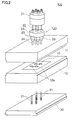
図1に示すように、成形金型100は、固定金型11と、可動金型12と、ホットランナー部20と、エジェクタープレート30とを備える。
固定金型11は、第1の金型として不図示の固定盤に支持されて固定されている。固定金型11は、可動金型12に対向する分割面PP側に第1転写面11aを有する。冷却路11bは、冷却水等を流すためのものであり、固定金型(第1の金型)11の過熱を防止するとともに溶融した樹脂を冷却するために設けられている。
可動金型12は、第2の金型として不図示の可動盤に支持されて固定金型11に対して進退可能になっている。可動金型12は、固定金型11に対向する分割面PP側に第2転写面12aを有する。可動金型12の第2転写面12aと固定金型11の第1転写面11aとの間には、型締めによってキャビティCVが形成される。冷却路12bは可動金型(第2の金型)12の過熱を防止するとともに溶融した樹脂を冷却するために設けられている。
図2に示すように、可動金型12には、複数の第2転写面12aが形成されている。固定金型11にも、図示されていないが、上記複数の第2転写面12aに対向して複数の第1転写面11aが形成されている。
図1に戻って、ホットランナー部20は、キャビティCVに樹脂を供給するための部分である。ホットランナー部20の先端部は固定金型11に埋め込まれており、根元部は固定金型11の背後に延びている。ホットランナー部20は、ニードル22とノズル部24とを備える。
図2に示すように、固定金型(第1の金型)11には、複数の第2転写面12aすなわち複数のキャビティCVに対応して、複数のホットランナー部20が組み付けられている。これら複数のホットランナー部20と、これらのホットランナー部20を支持するノズル保持リング23と、これらのホットランナー部20を動作させるエアーシリンダー21とは、ホットランナー装置120を構成する。ホットランナー装置120は、型締めされた固定金型11及び可動金型12間に形成された複数のキャビティCV(図1参照)に溶融樹脂を供給する。
図1に戻って、ノズル部24に挿入されるニードル22は、図2のエアーシリンダー21によってAB方向に昇降駆動される。ノズル部24には、ヒーター25と温度センサー26とが設けられ、それぞれのノズル部24において独立して温度制御が行われる。ニードル22は、ガイド27によって摺動可能に保持され、ノズル部24の先端であるノズル端24aがニードル22の進退に伴って開閉される。ノズル端24aに設けた開口であるゲートが開放されると、ノズル端24aに導かれた溶融樹脂がキャビティCV内に射出される。ニードル22は、分割面PPに垂直な方向(可動金型12の可動方向)に延びており、ノズル部24も分割面PPに垂直な方向に延びている。これにより、ノズル端24aからの溶融樹脂射出方向は、分割面PPに垂直であって、可動金型12の可動方向と平行になる。
エジェクタープレート30は、不図示の駆動装置に付勢されて、成形金型100の軸に沿った上下のAB方向に沿って所望のタイミングで昇降させることができる。エジェクタープレート30には、複数のエジェクターピン31が固定されており、各エジェクターピン31は、可動金型12に設けたピン孔12fに通されている。エジェクターピン31の先端は、固定金型11と可動金型12とが型締めされた図示の状態でキャビティCVに臨んだ状態になる。
成形金型100の動作について説明すると、互いに離間した型開き状態の固定金型11と可動金型12とは、待機状態において所定の温度に調節される。その後、可動金型12を動作させて上昇させ、固定金型11と可動金型12とを型閉じし、所定の圧力で両金型11,12を型締めする。この際、両金型11,12間にはキャビティCVが形成される。この状態でエアーシリンダー21を動作させてニードル22を上方に移動させると、通路28からノズル端24aに導かれた溶融樹脂が先端のゲートからキャビティCV中に射出される。溶融樹脂がキャビティCVに充分に充填されると、ニードル22が下方に移動し、ノズル端24aを密閉する。キャビティCV中の溶融樹脂は、両金型11,12によって冷却され、成形品としてのレンズ10が得られる。この状態で可動金型12を固定金型11から離間させる型開きを行うと、レンズ10は、固定金型11から離型され、可動金型12に付着した状態となる。次に、エジェクタープレート30を上昇させてエジェクターピン31に突き出しを行わせると、レンズ10が可動金型12から剥離され、レンズ10の離型が完了する。
図3A及び3Bに示すように、レンズ10は、光学的機能を有する本体部分10aと、本体部分10aの周囲に設けられたフランジ部10bとを有する。本体部分10aは、一対の対向する第1及び第2光学面S1,S2を有し、フランジ部10bは、一対の対向する第1及び第2フランジ面S3,S4を有するとともに、フランジ面S3,S4を連結する側面S5を有する。フランジ部10bの外側に拡張するように設けられた突起10cは、肉薄で扁平に形成された部分であり、具体的には、矩形の板状部分となっている。なお、第1及び第2フランジ面S3,S4等は、レンズ10の光軸OAに平行に延びている。
突起10cの寸法については、レンズ10の直径をDとし、ノズル端24aの開口であるゲート径をGとしたときに、突起10cの長さLは、
2G≦L≦D
となるようにする。この範囲とすることで、突起10cに対応する空間をある程度以上確保することで流動性が良好になり、かつ、突起10cが過度に大きくなって後工程においてレンズの組み付け等の邪魔になることを防止できる。
また、突起10cの高さHは、
G/2≦H≦5G
となるようにする。この範囲とすることで、流動性が良好となる。
また、突起10cの幅Wは、
G≦W≦5G
となるようにする。この範囲とすることで、流動性が良好になり、かつ、後工程においてレンズの組み付け等の邪魔になりにくい。
2G≦L≦D
となるようにする。この範囲とすることで、突起10cに対応する空間をある程度以上確保することで流動性が良好になり、かつ、突起10cが過度に大きくなって後工程においてレンズの組み付け等の邪魔になることを防止できる。
また、突起10cの高さHは、
G/2≦H≦5G
となるようにする。この範囲とすることで、流動性が良好となる。
また、突起10cの幅Wは、
G≦W≦5G
となるようにする。この範囲とすることで、流動性が良好になり、かつ、後工程においてレンズの組み付け等の邪魔になりにくい。
図4に示すように、第1光学面S1は、固定金型11の第1転写面11aに対応する形状を有し、第1転写面11aの転写によって形成される。第2光学面S2は、可動金型12の第2転写面12aに対応する形状を有し、第2転写面12aの転写によって形成される。第1フランジ面S3は、固定金型11の第3転写面11cの転写によって形成される。第2フランジ面S4及び側面S5は、可動金型12の第4転写面12dの転写によって形成される。フランジ部10bの一箇所から半径方向の外側に延びる突起10cは、固定金型11の突起転写面11iと可動金型12の突起転写面12iとによって画成される成形空間部分CV2に対応して成形される。ノズル部24のノズル端24aは、固定金型11の突起転写面11iを介してキャビティCVに連通している。つまり、ノズル端24aがレンズ10の突起10cに対応する成形空間部分CV2に望むような供給位置SPに配置され溶融樹脂を光軸OA方向に沿って注入する。
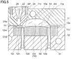
図5は、変形例の成形金型を説明する部分拡大断面図であり、図4に対応している。この場合、可動金型12の突起転写面12i等の形状が変更されている。先端壁12mと側壁12nとは、成形空間部分CV2の中心からレンズ10すなわちキャビティCVの中心に向かう軸線AXに対してレンズ10すなわちキャビティCVの中心に向かうほど距離が広がる傾斜面となっている。なお、可動金型12の突起転写面12iの対向壁(突起転写面11i)については、傾斜せず、型開閉のAB方向に垂直になっている。
図6A及び6Bは、図5の成形金型によって形成されるレンズ10を説明する断面図及び平面図である。この場合、レンズ10に設けられた突起10cは、湾曲した傾斜面である側面10xと平坦な傾斜面である先端面10yとを有する。側面10x及び先端面10yは、突起10cの中心からレンズ10の中心に向かう軸線AXに対してレンズ10の中心に向かうほど距離が広がる傾斜面となっている。言い換えると、例えば、図6Aに示すように、突起10cの先端面10yの高さについて見れば、レンズ10の中心から離れた部分の高さT1よりもレンズ10の中心に近い部分の高さT2の方が高くなっている。
図5のような成形金型を用いた場合、傾斜面である先端面10y及び側面10xによってレンズ10の中央部に向かうような整った溶融樹脂の流れが形成されやすく、溶融樹脂の流動性を高めて転写性を向上させることができる。
上記実施形態の成形金型100及びこれを用いた製造方法では、ノズル端24aがレンズ10の第1及び第2光学面S1,S2を設けた本体部分10aを除いた部分であるフランジ部10bの外側に拡張した突起10cに対応する供給位置SPに配置され溶融樹脂を光軸OA方向に沿って注入する。そのため、レンズ10の光学面S1,S2にノズル跡(ゲート跡)が残ることを防止できる。これにより、ホットランナー形式の利点を生かしつつ、レンズ10の光学性能を高めることができる。また、レンズ10に残る突起10cは、小さくすることができ、後工程であるレンズ10の組み付け等に際して邪魔になりにくい。レンズ10が既にコールドランナー形式で成形されていたものである場合、突起10cを追加するだけで足り、形状変更を最小限とすることができる。なお、ホットランナー部20を組み込んだ成形金型100を用いるレンズの製造方法により、レンズ10を取り出す際にゲートカットが不要となり、廃材をなくすことができる。また、レンズ10のみの冷却で製品を硬化させることができるので、サイクルタイムを短くすることができ、エネルギー効率もよい。
〔第2実施形態〕
以下、第2実施形態の成形金型等について説明する。第2実施形態の成形金型等は、第1実施形態の成形金型等を部分的に変更したものであり、特に説明しない事項は、第1実施形態の成形金型等と同様である。
以下、第2実施形態の成形金型等について説明する。第2実施形態の成形金型等は、第1実施形態の成形金型等を部分的に変更したものであり、特に説明しない事項は、第1実施形態の成形金型等と同様である。
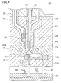
図7に示すように、固定金型11の第1転写面11aの曲率(絶対値)は、可動金型12の第2転写面12aの曲率(絶対値)よりも小さくなっている。このため、固定金型11の第1転写面11aにおける窪みが浅くなるので、ノズル部24のノズル端24a周辺の配置や形状の自由度が高まり、ノズル端24aを第1転写面11aの外縁に近づけることができる。よって、第2実施形態の成形金型100の場合、ノズル部24のノズル端24aは、固定金型11の第3転写面11cを介してキャビティCVに連通している。つまり、本実施形態の場合、ノズル端24aがレンズ10のフランジ部10bに対応する成形空間部分CV3に臨むような供給位置SPに配置され溶融樹脂を光軸OA方向に沿って注入する。
図8A及び8Bは、図7の成形金型100によって得たレンズ10の断面図及び平面図である。レンズ10に設けた一対の対向する第1及び第2光学面S1,S2は、固定金型11の第1転写面11aと、可動金型12の第2転写面12aとにそれぞれ対応する形状を有する。そして、フランジ部10bの一部が成形金型100の供給位置SPに対応するので、図3A等に示す突起10cが存在しない。
〔第3実施形態〕
以下、第3実施形態の成形金型等について説明する。第3実施形態の成形金型等は、第1実施形態の成形金型等を部分的に変更したものであり、特に説明しない事項は、第1実施形態の成形金型等と同様である。
以下、第3実施形態の成形金型等について説明する。第3実施形態の成形金型等は、第1実施形態の成形金型等を部分的に変更したものであり、特に説明しない事項は、第1実施形態の成形金型等と同様である。
図9及び図10に示すように、固定金型11の第1転写面11aの曲率(絶対値)は、可動金型12の第2転写面12aの曲率(絶対値)よりも大きいが、固定金型11の第3転写面11cの一部に窪み11zが形成されている。そして、第3実施形態の成形金型100の場合、ノズル部24のノズル端24aを、固定金型11の窪み11zを介して成形空間部分CV3及びキャビティCVに連通させている。つまり、本実施形態の場合、ノズル端24aを窪み11zの深さ分だけ分割面PPから離すことにより、ノズル部24と第1転写面11aとの干渉を回避している。結果的に、図9の成形金型100により、固定金型11の第1転写面11aの曲率を大きくする等、形状の自由度が高まる。
図11A及び11Bは、図9の成形金型100によって得たレンズ10の断面図及び平面図である。レンズ10に設けた一対の対向する第1及び第2光学面S1,S2は、固定金型11の第1転写面11aと、可動金型12の第2転写面12aとにそれぞれ対応する形状を有する。そして、レンズ10のフランジ部10bの一部には、光軸OA方向に突出する突起10pが形成されている。この突起10pが固定金型11の窪み11zに対応し、その頂部がノズル部24による溶融樹脂の供給跡になる。
〔第4実施形態〕
以下、第4実施形態の成形金型等について説明する。第4実施形態の成形金型等は、第1実施形態の成形金型等を部分的に変更したものであり、特に説明しない事項は、第1実施形態の成形金型等と同様である。
以下、第4実施形態の成形金型等について説明する。第4実施形態の成形金型等は、第1実施形態の成形金型等を部分的に変更したものであり、特に説明しない事項は、第1実施形態の成形金型等と同様である。
図12に示すように、固定金型11の第1転写面11aの直径は、可動金型12の第2転写面12aの直径よりも小さくなっている。つまり、固定金型11において、レンズ10の第1光学面S1を成形するための第1転写面11aと、レンズ10の第1フランジ面S3を成形するための第3転写面11cとの間に輪帯部11qが形成されている。つまり、輪帯部11qは、第1転写面11aの外側に隣接して形成されており、第1転写面11aと第2転写面12aとの直径差に対応する幅を有している。本実施形態の場合、輪帯部11qの一部は、ノズル端24aが配置される供給位置SPとなる。
図13A及び13Bは、図12の成形金型100によって得たレンズ10の断面図及び平面図である。レンズ10に設けた一対の対向する第1及び第2光学面S1,S2は、固定金型11の第1転写面11aと、可動金型12の第2転写面12aとにそれぞれ対応する形状を有する。第1光学面S1の直径は、第2光学面S2の直径よりもかなり小さい。第1光学面S1は、本体部分10aの中央領域のみに形成されている。第1光学面S1の周囲には、輪帯面10qが形成されている。
本実施形態の場合、光学的に活用されていない輪帯面10qを形成する輪帯部11qの一部を活用して溶融樹脂の注入を行うことができる。
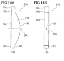
以上、実施形態に即して本発明を説明したが本発明は、上記実施形態に限定されるものではない。例えば上記実施形態では、レンズ10の本体部分10aやフランジ部10bが円形の輪郭を有するとしているが、本体部分10aやフランジ部10bは矩形の輪郭を有する場合もある。例えば図14A及び14Bに示すように、細長いレンズ510を図1等に例示する成形金型100によって形成するともできる。図示のレンズ510も、本体部分10aやフランジ部10bを有し、フランジ部10bを外側に拡張するように突起10cが設けられている。この突起10cは、ノズル部24による溶融樹脂の供給跡を有する。
また、本発明は、様々なレンズに対して用いることができる。例えば、撮像用レンズや光ディスク用ピックアップレンズは、要求される光学性能が高いため、低複屈折で高価な樹脂材料を使用する。そのため、本技術を用いると、スプルーやランナーを必要としないため、使用する樹脂材料を削減でき、低コストで生産することが出来る。突起10cが不要な場合は後工程にて切断することもできるし、切断せずにレンズホルダーとの位置決めに使用することもできる。また、LEDバックライト用光拡散レンズの場合は、要求される光学性能が比較的低いため、低コストで生産することが求められる。本発明を用いると、成形時の樹脂圧力伝達が良いため、樹脂温度や金型温度を低くしてサイクルタイムを短くしても十分なレンズ面精度を達成でき、生産コストを低くすることができる。
上記実施形態では、ノズル部24が分割面PPに垂直な方向に延び、ノズル端24aからの溶融樹脂の射出方向を可動金型12の可動方向と平行となるようにしているが、ここで、可動方向と平行であるとは、厳密なものではなく、溶融樹脂の射出方向が可動金型12の可動方向に対して多少傾いていてもよい。
上記実施形態では、単一の本体部分10aを有するレンズ10の成形について説明したが、複数の本体部分10aを有するレンズ10を図1、7、9、12等に例示した成形金型100によって形成するともできる。
第1実施形態において、可動金型12の突起転写面12iの対向壁である突起転写面11iは、成形空間部分CV3の中心からレンズ10の中心に向かう軸線AXに対してレンズ10の中心に向かうほど距離が広がる傾斜面を有していてもよい。
以上の説明では、成形金型100を竪型としているが、成形金型100を横型とすることもできる。この場合、固定金型11と可動金型12とが水平方向に対向して配置される。
Claims (8)
- レンズの第1光学面を成形する第1転写面を有する第1の金型と、
前記レンズの第2光学面を成形する第2転写面を有する第2の金型と、
前記第1の金型側に配置され、前記第1の金型と前記第2の金型との分割面に近接するノズル端を有するホットランナーとを備え、
前記ノズル端は、前記レンズの第1及び第2光学面を除いた部分に対応する供給位置に樹脂を光軸方向に沿って注入するように配置される成形金型。 - 前記供給位置は、前記レンズのフランジ部の外側に拡張した突起に対応する、請求項1に記載の成形金型。
- 前記供給位置は、前記突起に対応する肉薄で扁平な成形空間部分に臨み、
前記成形空間部分の先端壁、側壁、及び対向壁のうち少なくとも1つは、前記成形空間部分の中心から前記レンズの中心に向かう軸線に対して前記レンズの中心に向かうほど距離が広がる傾斜面を有する、請求項2に記載の成形金型。 - 前記供給位置は、前記レンズのフランジ部に対応する、請求項1に記載の成形金型。
- 前記供給位置は、前記レンズのフランジ部に設けられた突起に対応する、請求項1に記載の成形金型。
- 前記ノズル端が配置される前記第1の金型側の前記第1転写面の直径は、対向する前記第2転写面の直径よりも小さく、
前記供給位置は、前記第1転写面の外側に隣接する輪帯部に対応する、請求項1に記載の成形金型。 - 前記ノズル端が配置される前記第1の金型側の前記第1転写面の曲率は、対向する前記第2転写面の曲率よりも小さい、請求項1に記載の成形金型。
- レンズの第1光学面を成形する第1転写面を有する第1の金型と、前記レンズの第2光学面を成形する第2転写面を有する第2の金型と、前記第1の金型側に配置され前記第1の金型と前記第2の金型との分割面に近接するノズル端を有するホットランナーとを備える成形金型を用いたレンズの製造方法であって、
前記ノズル端は、前記レンズの第1及び第2光学面を除いた部分に対応する供給位置に配置され、樹脂を光軸方向に沿って注入するレンズの製造方法。
Applications Claiming Priority (2)
| Application Number | Priority Date | Filing Date | Title |
|---|---|---|---|
| JP2012077810 | 2012-03-29 | ||
| JP2012-077810 | 2012-03-29 |
Publications (1)
| Publication Number | Publication Date |
|---|---|
| WO2013147106A1 true WO2013147106A1 (ja) | 2013-10-03 |
Family
ID=49260349
Family Applications (1)
| Application Number | Title | Priority Date | Filing Date |
|---|---|---|---|
| PCT/JP2013/059421 Ceased WO2013147106A1 (ja) | 2012-03-29 | 2013-03-28 | 成形金型及びレンズの製造方法 |
Country Status (1)
| Country | Link |
|---|---|
| WO (1) | WO2013147106A1 (ja) |
Cited By (1)
| Publication number | Priority date | Publication date | Assignee | Title |
|---|---|---|---|---|
| CN109664476A (zh) * | 2019-01-08 | 2019-04-23 | 东莞市美光达光学科技有限公司 | 一种避免成型脱模时变形的光学镜片模具脱模结构 |
Citations (3)
| Publication number | Priority date | Publication date | Assignee | Title |
|---|---|---|---|---|
| JPH1058496A (ja) * | 1996-08-27 | 1998-03-03 | Konica Corp | レンズ部品製造方法及びその装置並びにレンズ部品 |
| JPH11207790A (ja) * | 1998-01-29 | 1999-08-03 | Konica Corp | 光学部品の成型方法、ホットランナー形式の金型を使用した成型機、及び光学部品 |
| JP2008055713A (ja) * | 2006-08-30 | 2008-03-13 | Sumitomo Heavy Ind Ltd | 射出成形機、金型、及び射出成形方法 |
-
2013
- 2013-03-28 WO PCT/JP2013/059421 patent/WO2013147106A1/ja not_active Ceased
Patent Citations (3)
| Publication number | Priority date | Publication date | Assignee | Title |
|---|---|---|---|---|
| JPH1058496A (ja) * | 1996-08-27 | 1998-03-03 | Konica Corp | レンズ部品製造方法及びその装置並びにレンズ部品 |
| JPH11207790A (ja) * | 1998-01-29 | 1999-08-03 | Konica Corp | 光学部品の成型方法、ホットランナー形式の金型を使用した成型機、及び光学部品 |
| JP2008055713A (ja) * | 2006-08-30 | 2008-03-13 | Sumitomo Heavy Ind Ltd | 射出成形機、金型、及び射出成形方法 |
Cited By (2)
| Publication number | Priority date | Publication date | Assignee | Title |
|---|---|---|---|---|
| CN109664476A (zh) * | 2019-01-08 | 2019-04-23 | 东莞市美光达光学科技有限公司 | 一种避免成型脱模时变形的光学镜片模具脱模结构 |
| CN109664476B (zh) * | 2019-01-08 | 2024-05-28 | 东莞市美光达光学科技有限公司 | 一种避免成型脱模时变形的光学镜片模具脱模结构 |
Similar Documents
| Publication | Publication Date | Title |
|---|---|---|
| JP6517973B2 (ja) | 射出成形金型 | |
| JP4335266B2 (ja) | 導光板の射出圧縮成形金型および導光板の射出圧縮成形方法 | |
| KR101822565B1 (ko) | 핫 러너를 적용한 렌즈용 사출 성형품 | |
| KR101678958B1 (ko) | 사출금형의 보스부위 싱크마크 생성방지 장치 | |
| US10022926B2 (en) | Injection molding method and injection molding die | |
| WO2013147106A1 (ja) | 成形金型及びレンズの製造方法 | |
| CN214645411U (zh) | 一种微流控离心式测试卡盘镜面模具 | |
| JP4958592B2 (ja) | レンズ用成形金型およびプラスチックレンズ | |
| KR20170001668U (ko) | 광 렌즈 및 광 렌즈 몰드 | |
| JP2008155577A (ja) | レンズ成形用金型およびレンズの製造方法 | |
| US20100255143A1 (en) | Gas-assisted mold surface heating system | |
| CN214687756U (zh) | 一种扩散透镜的注塑模具 | |
| CN111267298B (zh) | 一种空调导轨塑料模具及其制造方法 | |
| JP4847782B2 (ja) | モールド射出成形金型 | |
| JP2008230005A (ja) | プラスチックレンズ成形方法およびレンズプリフォーム | |
| CN210100534U (zh) | 基于针阀式热流道的免剪浇电动车前挡泥板注塑模具 | |
| JP2013212593A (ja) | 成形品の製造方法及び製造装置 | |
| JP2014061597A (ja) | 成形装置及び光学素子の製造方法 | |
| JP2020179635A (ja) | 微細パターン転写用モールド及び微細パターン成形方法 | |
| JP2012158088A (ja) | 光学素子の製造方法及び成形金型 | |
| JP2009285913A (ja) | 射出圧縮成形金型、射出圧縮成形金型の調整方法、および射出圧縮成形システム | |
| JPWO2013146871A1 (ja) | 熱可塑性樹脂製品の製造方法及び装置 | |
| JP2005324503A (ja) | 金型の冷却方法、樹脂成形方法、樹脂成形装置、金型 | |
| JP2009149107A (ja) | 導光板の射出圧縮成形金型および導光板の射出圧縮成形方法 | |
| JP2014061601A (ja) | 光学素子の製造方法 |
Legal Events
| Date | Code | Title | Description |
|---|---|---|---|
| 121 | Ep: the epo has been informed by wipo that ep was designated in this application |
Ref document number: 13770308 Country of ref document: EP Kind code of ref document: A1 |
|
| 122 | Ep: pct application non-entry in european phase |
Ref document number: 13770308 Country of ref document: EP Kind code of ref document: A1 |
|
| NENP | Non-entry into the national phase |
Ref country code: DE |
|
| NENP | Non-entry into the national phase |
Ref country code: JP |