WO2013146473A1 - 田植機 - Google Patents
田植機 Download PDFInfo
- Publication number
- WO2013146473A1 WO2013146473A1 PCT/JP2013/057835 JP2013057835W WO2013146473A1 WO 2013146473 A1 WO2013146473 A1 WO 2013146473A1 JP 2013057835 W JP2013057835 W JP 2013057835W WO 2013146473 A1 WO2013146473 A1 WO 2013146473A1
- Authority
- WO
- WIPO (PCT)
- Prior art keywords
- engine
- exhaust
- machine body
- generator
- fan
- Prior art date
- Legal status (The legal status is an assumption and is not a legal conclusion. Google has not performed a legal analysis and makes no representation as to the accuracy of the status listed.)
- Ceased
Links
Images


Classifications
-
- A—HUMAN NECESSITIES
- A01—AGRICULTURE; FORESTRY; ANIMAL HUSBANDRY; HUNTING; TRAPPING; FISHING
- A01C—PLANTING; SOWING; FERTILISING
- A01C11/00—Transplanting machines
- A01C11/003—Transplanting machines for aquatic plants; for planting underwater, e.g. rice
-
- B—PERFORMING OPERATIONS; TRANSPORTING
- B60—VEHICLES IN GENERAL
- B60K—ARRANGEMENT OR MOUNTING OF PROPULSION UNITS OR OF TRANSMISSIONS IN VEHICLES; ARRANGEMENT OR MOUNTING OF PLURAL DIVERSE PRIME-MOVERS IN VEHICLES; AUXILIARY DRIVES FOR VEHICLES; INSTRUMENTATION OR DASHBOARDS FOR VEHICLES; ARRANGEMENTS IN CONNECTION WITH COOLING, AIR INTAKE, GAS EXHAUST OR FUEL SUPPLY OF PROPULSION UNITS IN VEHICLES
- B60K13/00—Arrangement in connection with combustion air intake or gas exhaust of propulsion units
- B60K13/04—Arrangement in connection with combustion air intake or gas exhaust of propulsion units concerning exhaust
-
- B—PERFORMING OPERATIONS; TRANSPORTING
- B60—VEHICLES IN GENERAL
- B60K—ARRANGEMENT OR MOUNTING OF PROPULSION UNITS OR OF TRANSMISSIONS IN VEHICLES; ARRANGEMENT OR MOUNTING OF PLURAL DIVERSE PRIME-MOVERS IN VEHICLES; AUXILIARY DRIVES FOR VEHICLES; INSTRUMENTATION OR DASHBOARDS FOR VEHICLES; ARRANGEMENTS IN CONNECTION WITH COOLING, AIR INTAKE, GAS EXHAUST OR FUEL SUPPLY OF PROPULSION UNITS IN VEHICLES
- B60K11/00—Arrangement in connection with cooling of propulsion units
- B60K11/06—Arrangement in connection with cooling of propulsion units with air cooling
-
- B—PERFORMING OPERATIONS; TRANSPORTING
- B60—VEHICLES IN GENERAL
- B60K—ARRANGEMENT OR MOUNTING OF PROPULSION UNITS OR OF TRANSMISSIONS IN VEHICLES; ARRANGEMENT OR MOUNTING OF PLURAL DIVERSE PRIME-MOVERS IN VEHICLES; AUXILIARY DRIVES FOR VEHICLES; INSTRUMENTATION OR DASHBOARDS FOR VEHICLES; ARRANGEMENTS IN CONNECTION WITH COOLING, AIR INTAKE, GAS EXHAUST OR FUEL SUPPLY OF PROPULSION UNITS IN VEHICLES
- B60K5/00—Arrangement or mounting of internal-combustion or jet-propulsion units
- B60K5/04—Arrangement or mounting of internal-combustion or jet-propulsion units with the engine main axis, e.g. crankshaft axis, transversely to the longitudinal centre line of the vehicle
-
- B—PERFORMING OPERATIONS; TRANSPORTING
- B60—VEHICLES IN GENERAL
- B60K—ARRANGEMENT OR MOUNTING OF PROPULSION UNITS OR OF TRANSMISSIONS IN VEHICLES; ARRANGEMENT OR MOUNTING OF PLURAL DIVERSE PRIME-MOVERS IN VEHICLES; AUXILIARY DRIVES FOR VEHICLES; INSTRUMENTATION OR DASHBOARDS FOR VEHICLES; ARRANGEMENTS IN CONNECTION WITH COOLING, AIR INTAKE, GAS EXHAUST OR FUEL SUPPLY OF PROPULSION UNITS IN VEHICLES
- B60K5/00—Arrangement or mounting of internal-combustion or jet-propulsion units
- B60K5/12—Arrangement of engine supports
- B60K5/1208—Resilient supports
- B60K5/1216—Resilient supports characterised by the location of the supports relative to the motor or to each other
-
- B—PERFORMING OPERATIONS; TRANSPORTING
- B60—VEHICLES IN GENERAL
- B60Y—INDEXING SCHEME RELATING TO ASPECTS CROSS-CUTTING VEHICLE TECHNOLOGY
- B60Y2200/00—Type of vehicle
- B60Y2200/20—Off-Road Vehicles
- B60Y2200/22—Agricultural vehicles
-
- F—MECHANICAL ENGINEERING; LIGHTING; HEATING; WEAPONS; BLASTING
- F02—COMBUSTION ENGINES; HOT-GAS OR COMBUSTION-PRODUCT ENGINE PLANTS
- F02B—INTERNAL-COMBUSTION PISTON ENGINES; COMBUSTION ENGINES IN GENERAL
- F02B67/00—Engines characterised by the arrangement of auxiliary apparatus not being otherwise provided for, e.g. the apparatus having different functions; Driving auxiliary apparatus from engines, not otherwise provided for
- F02B67/04—Engines characterised by the arrangement of auxiliary apparatus not being otherwise provided for, e.g. the apparatus having different functions; Driving auxiliary apparatus from engines, not otherwise provided for of mechanically-driven auxiliary apparatus
Definitions
- the present invention relates to a rice transplanter having a seedling stand and a plurality of planting claws and continuously performing seedling planting operations.
- the present invention has been made in view of the above situation, and provides a rice transplanter in which peripheral parts such as cooling system parts and power transmission system parts are efficiently and compactly arranged around the engine while improving cooling efficiency. Is a technical issue.
- the invention of claim 1 includes an engine mounted on a traveling machine body, a transmission case that shifts the power of the engine and transmits it to a traveling part of the traveling machine body, and a seedling planting device mounted on the traveling machine body.
- a rice transplanter provided with a suction fan for engine air cooling on one side of the engine, the other side of the engine opposite to the suction fan being an output projecting from the other side
- An exhaust pipe communicating with the exhaust system of the engine is extended on one side of the shaft, and a generator is arranged on the other side.
- the engine is mounted on an engine base attached to the traveling machine body via a vibration isolation member, and the tension applying member is mounted on the engine base.
- the generator is attached to a fixed bracket fastened to the other side of the engine.
- the engine includes an engine mounted on a traveling machine body, a transmission case that shifts the power of the engine and transmits it to a traveling unit of the traveling machine body, and a seedling planting device that is mounted on the traveling machine body.
- a suction fan for engine air cooling is provided on one side of the engine, and an output shaft protruding from the other side is provided on the other side of the engine opposite to the suction fan. Since the exhaust pipe communicating with the exhaust system of the engine is extended on one side and the generator is arranged on the other side, the exhaust pipe and the generator are distributed on both sides of the output shaft, The exhaust pipe and the generator can be arranged in a compact manner on the other side of the engine while suppressing adverse effects on the generator due to the heat of the exhaust pipe.
- the output pulley fixed to the output shaft, the transmission belt wound around the transmission input pulley fixed to the transmission input shaft of the transmission case, and the tension for tensioning the transmission belt A tensioning member, and the generator is positioned between the output pulley and the mission input pulley, so that the space between the engine and the mission case is effectively utilized.
- the arrangement of the pulley and the belt transmission system in the transmission case can be made compact.
- the said engine is mounted in the engine stand attached to the said traveling body via the vibration isolator, the said tension
- the left side in the traveling direction of the traveling machine body 2 is simply referred to as the left side
- the right side in the traveling direction is also simply referred to as the right side.
- the rice transplanter 1 includes a traveling machine body 2 supported by a pair of left and right front wheels 3 and a pair of left and right rear wheels 4 as a traveling unit.
- An engine 5 is mounted on the front part of the traveling machine body 2, and the power from the engine 5 is transmitted to the rear transmission case 6 to drive the front wheels 3 and the rear wheels 4 so that the vehicle travels forward and backward.
- a front axle case 7 projects from the left and right sides of the transmission case 6, and the front wheels 3 are attached to a front axle extending from the front axle case 7 to the left and right so as to be steerable.
- a cylindrical frame 8 is projected behind the transmission case 6, a rear axle case 9 is fixed to the rear end side of the cylindrical frame 8, and the rear wheel 4 is attached to a rear axle that extends outward from the rear axle case 9 to the left and right. Yes.
- an operator boarding work step (vehicle body cover) 10 is provided on the upper surface side of the front part and the central part of the traveling machine body 2.
- a front bonnet 11 is disposed above the front part of the work step 10, and the engine 5 is installed inside the front bonnet 11.
- a traveling speed change pedal 12 for stepping operation is disposed on the upper side of the work step 10 on the rear side of the front bonnet 11.
- a steering handle 14, a traveling main transmission lever 15, and a work lever 16 are provided in the driving operation unit 13 on the upper surface side of the rear portion of the front bonnet 11.
- a steering seat 18 is disposed via a seat frame 17 behind the front bonnet 11 on the upper surface of the work step 10.
- left and right spare seedling platforms 24 are provided on the left and right sides of the front bonnet 11 with the operation step 10 interposed therebetween.
- the link frame 19 is erected at the rear end of the traveling machine body 2.
- a seedling planting device 23 for 8-row planting is connected to the link frame 19 via a parallel link mechanism 22 including a lower link 20 and a top link 21 so as to be movable up and down.
- the operator gets on the work step 10 from the boarding / alighting step 25 on the side of the work step 10 and drives the seedling planting device 23 to move the seedling planting device 23 and move the seedling planting in the field while moving in the field by the driving operation. Perform work (rice planting work).
- the operator replenishes the seedling planting device 23 with a seedling mat on the preliminary seedling mounting table 24 as needed.
- the seedling planting device 23 includes a planting input case 26 to which power is transmitted from the engine 5 via the mission case 6, and an 8-strip 4 connected to the planting input case 26.
- the seedling planting mechanism 28 is provided with a rotary case 31 having two planting claws 30 for one line. Two planted rotary cases 31 are arranged in the planting transmission case 27. By one rotation of the rotary case 31, the two planting claws 30 cut and grasp one seedling each, and plant it on the field leveled by the float 32.
- the power from the engine 5 via the transmission case 6 is transmitted not only to the front wheels 3 and the rear wheels 4, but also to the planting input case 26 of the seedling planting device 23.
- the power from the transmission case 6 toward the seedling planting device 23 is once transmitted to an inter-plant transmission case (not shown) provided on the upper right side of the rear axle case 9, and the motive power is transmitted from the inter-plant transmission case to the planting input case 26.
- the seedling planting mechanism 28 and the seedling mount 29 are driven by the transmitted power.
- the inter-strain shifting case includes an inter-strain shifting mechanism that switches between planted seedlings to, for example, sparse planting, standard planting, or dense planting, and a PTO clutch that interrupts power transmission to the seedling planting device 23. Is built-in.
- a side marker 33 is provided on the left and right outside of the seedling planting device 23.
- the side marker 33 includes a marker ring body 34 for muscle pulling and a marker arm 35 that pivotally supports the marker ring body 34 so as to be rotatable.
- the base end side of each marker arm 35 is pivotally supported on the left and right outer sides of the seedling planting device 23 so as to be rotatable left and right.
- the side marker 33 is moved away from the surface by raising the marker wheel body 34 based on the operation posture of the operation lever 16 in the driving operation unit 13 and forming a trajectory as a reference in the next process by landing on the surface.
- the non-working posture is configured to be rotatable.
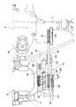
- the traveling machine body 2 includes a pair of left and right machine body frames 50 extending in the front-rear direction.
- Each body frame 50 is divided into a front frame 51 and a rear frame 52.
- the rear end portion of the front frame 51 and the front end portion of the rear frame 52 are welded and fixed to a laterally long intermediate connection frame 53.
- the front ends of the pair of left and right front frames 51 are fixed to the front frame 54 by welding.
- the rear end sides of the left and right rear frames 52 are fixed to the rear frame 55 by welding.
- the front frame 54, the left and right front frames 51, and the intermediate connection frame 53 are configured in a square frame shape in plan view.
- the intermediate connection frame 53, the left and right rear frames 52, and the rear frame 55 are also configured in a square frame shape in plan view.
- the front portions of the left and right front frames 51 are connected by two front and rear base frames 56.
- Each of the base frames 56 is formed in a shape that is bent in a U shape so that an intermediate portion thereof is positioned lower than the left and right front frames 51.
- the left and right ends of each base frame 56 are fixed by welding to the corresponding front frames 51.
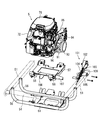
- the engine 5 is mounted on and supported by the front and rear base frames 56 through a substantially flat engine stand 57 and a plurality of vibration isolating rubbers 58 as vibration isolating members.
- the front base frame 56 is connected to the front frame 54 via a front relay frame 59 fixedly welded thereto.
- the rear base frame 56 is connected to the front portion of the transmission case 6 via the rear relay bracket 60.
- the engine 5 of the embodiment is a 4-stroke V-type 2-cylinder gasoline engine.
- the rear portions of the left and right front frames 51 are connected to a front axle case 7 protruding from the left and right sides of the mission case 6.
- the left and right ends of a U-shaped frame 61 extending rearward and obliquely downward in a side view are welded and fixed to the center side of the intermediate connection frame 53.
- the middle part of the U-shaped frame 61 is connected to the middle part of the cylindrical frame 8 that connects the transmission case 6 and the rear axle case 9 (see FIGS. 3 and 4).
- the upper end sides of the left and right vertical frames 62 are welded and fixed to the middle portion of the rear frame 55.
- An intermediate portion of a laterally long rear axle support frame 63 is fixed by welding to the lower ends of the left and right vertical frames 62.
- the left and right ends of the rear axle support case 63 are connected to the rear axle case 9.
- a muffler 65 for reducing the exhaust noise of the engine 5 is disposed below the step support base 64 projecting outward from the left front frame 51.
- a power steering unit 66 is provided at the front portion of the transmission case 6 disposed behind the engine 5.
- a handle shaft (not shown) is rotatably disposed inside a handle post 67 erected on the upper surface of the power steering unit 66.
- a steering handle 14 is fixed to the upper end side of the handle shaft.
- a steering output shaft (not shown) protrudes downward.
- a steering rod 68 (see FIG. 4) for steering the left and right front wheels 6 is connected to the steering output shaft.
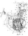
- the engine 5 of the embodiment is disposed on an intermediate portion of the front and rear base frames 56 with the output shaft 70 (crank shaft) directed in the left-right direction.
- the left and right widths of the engine 5 and the engine stand 57 are smaller than the inner dimensions between the left and right front frames 51, and the lower side of the engine 5 and the engine stand 57 are disposed on the middle part of the front and rear base frames 56. Thus, it is exposed below the left and right front frames 51.
- the output shaft 70 (axis line) of the engine 5 is in a position overlapping the left and right front frames 51 in a side view.
- the output shaft 70 of the engine 5 protrudes outward from the left and right side surfaces of the engine 5.
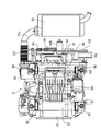
- a suction fan 71 for engine air cooling is provided at one protruding end portion (right protruding end portion in the embodiment) of the output shaft 70 (see FIG. 5).
- the suction fan 71 is configured to rotate integrally with the output shaft 70.
- the suction fan 71 is covered with a fan cover 72.
- a dustproof net 74 is provided at the cooling air intake 73 formed at the center of the fan cover 72.
- the engine 5 itself is forcibly cooled by the cooling air taken in from the cooling air intake 73 by the rotation of the suction fan 71.
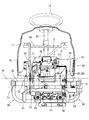
- cooling air (outside air) that cools the engine 5 from the left and right sides in the front bonnet 11 (also referred to as the engine room) toward the other (right side to left side in the embodiment) ) Is distributed. That is, a circulation port 75 through which cooling air is circulated inside and outside the front bonnet 11 is formed on the lower side of the left and right side surfaces of the front bonnet 11. In the embodiment, a plurality of slit-shaped through holes are formed on the left and right side surfaces of the front bonnet 11 so as to be arranged at appropriate intervals in the vertical direction. These through hole groups are formed in the circulation port 75.
- the suction fan 71 rotates, the air in the front bonnet 11 flows from the right side to the left side, the pressure in the front bonnet 11 decreases, and a difference occurs in the pressure inside and outside the front bonnet 11. Then, the cooling air is taken in from the right circulation port 75, the right front frame 51, and the lower side of the work step 10, and the engine 5 and the like are air-cooled by the taken cooling air. Cooling air (exhaust air) warmed by circulating through the front bonnet 11 is discharged out of the front bonnet 11 from the left circulation port 75, the left front frame 51, and the lower side of the work step 10 (FIG. 7).
- a cleaner case 76 that houses an air cleaner (not shown) is disposed on the upper surface of the engine 5 with an appropriate space therebetween in the vertical direction.
- a gap formed between the cleaner case 76 and the engine 5 penetrates left and right, and is configured as an upper ventilation path 77 (see FIG. 7) through which cooling air taken in by rotation of the suction fan 71 can pass.
- a communication hole for communicating the inside and outside of the cleaner case 76 is formed at a position near the suction fan 71 on the lower surface side of the cleaner case 76. Cooling air passing through the upper air passage 77 by the rotation of the suction fan 71 is introduced into the cleaner case 76 through the communication hole.
- the cleaner case 76 is connected to the intake system of the engine 5.
- the cooling air filtered by the air cleaner in the cleaner case 76 is sent to the intake system (carburetor or the like) of the engine 5.
- the intake system carburetor or the like
- the temperature rise in the cleaner case 76 is suppressed, and cold air is supplied to the intake system (carburetor, etc.) of the engine 5.
- the drive efficiency of the engine 5 can be improved.
- a first oil cooler 78 for cooling the engine oil is provided on the rear side of the engine 5.
- a second oil cooler 79 for cooling the engine oil that faces the cooling air intake port 73 is disposed outside the fan cover 72.
- the second oil cooler 79 is connected to the first oil cooler 78 and plays a role of supplementing the cooling capacity of the first oil cooler 78. Cooling air taken into the front bonnet 11 by the rotation of the suction fan 71 is blown to the first and second oil coolers 78 and 79, and the first and second oil coolers 78 and 79 (internal engine oil) are forcibly cooled.
- the second oil cooler 79 of the embodiment is located between the right front frame 51 and the right side surface of the engine 5 (on the fan cover 72 side), and is disposed so as to overlap the right front frame 51 in a side view. .
- the second oil cooler 79 is disposed on the lower side of the front bonnet 11 that covers the engine 5 from above and is opposed to the suction fan 71.
- a substantially box-shaped bonnet frame 80 surrounding the engine 5 is connected to the front frame 54 and the handle post 67.
- a mounting frame 82 is provided on the branch frame 81 that is welded and fixed to one side portion (right side portion in the embodiment) of the bonnet frame 80 so as to straddle up and down.
- a second oil cooler 79 is connected to the lower side of the mounting bracket 82 and faces the cooling air intake port 73 of the fan cover 72. For this reason, the second oil cooler 79 is cooled before the engine 5 mainly by the cooling air taken in from the lower part of the right front frame 51 and the work step 10 by the rotation of the suction fan 71. Become. Therefore, the cooling efficiency of the second oil cooler 79 can be improved without using a cooling fan dedicated to the second oil cooler 79, which contributes to the downsizing of the second oil cooler 79.
- An electrical component 83 such as a controller related to the engine 5 is mounted on the upper side of the mounting bracket 82.
- the electrical component 83 faces the distribution port 75 on the right side from the inside of the front bonnet 11.
- the cooling air passing through the right circulation port 75 by the rotation of the suction fan 71 is blown to the electrical component 83, and the electrical component 83 is cooled.
- the temperature rise of the electrical component 83 disposed around the engine 5 can be suppressed by the cooling air from the right circulation port 75.
- the adverse effect on the electrical component 83 due to the heat of the engine 5 can be avoided.
- the inlet side of the upper ventilation path 77 between the cleaner case 76 and the engine 5 is located on the opposite side of the right-hand circulation port 75 with the electrical component 83 interposed therebetween (see FIG. 7).
- the outlet side of the upper ventilation path 77 is open on the upper side of the other side surface (the left side surface in the embodiment) of the engine 5 opposite to the suction fan 71.
- a side duct-shaped ventilation duct 84 is attached to the upper side of the left side surface of the engine 5 so as to surround the outlet side of the upper ventilation path 77.
- the ventilation duct 84 is positioned higher than the left front frame 51 and faces the left circulation port 75 from the inside of the front bonnet 11.
- An upper exhaust path 85 of the engine 5 is formed by the ventilation duct 84.
- the exhausted air that has passed through the upper ventilation passage 77 and has been warmed by taking the heat of the engine 5 is exhausted from the left circulation port 75 to the outside of the front bonnet 11 through the ventilation duct 84.
- the presence of the ventilation duct 84 prevents the warm exhausted air from returning and staying in the front bonnet 11 and can smoothly exhaust the exhaust from the left circulation port 75, thereby improving exhaust air exhaust efficiency.
- the exhausted air that has been deprived of heat from the engine 5 is not only discharged outside the front bonnet 11 via the upper exhaust passage 85, but also on the left front frame 51 and the work step 10. It will also be discharged via the lower part of. That is, the lower part of the left front frame 51 and the work step 10 is formed in the lower exhaust path 86 of the engine 5.
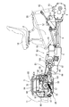
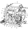
- An exhaust pipe 87 communicating with the exhaust system of the engine is disposed on the other side surface (left side surface in the embodiment) of the engine 5 opposite to the suction fan 71.
- the exhaust pipe 87 crosses between the ventilation duct 84 and the other protruding end portion (the left protruding end portion in the embodiment) of the output shaft 70, and then vertically extends on one side (the front side in the embodiment) across the output shaft 70. It is formed in an extended L shape.
- the exhaust pipe 87 of the embodiment includes a horizontal pipe portion 87a extending across the ventilation duct 84 and the output shaft 70, a vertical pipe portion 87b extending downward on the front side of the output shaft 70, and a vertical pipe portion 87b.
- connection pipe part 87c extended toward the muffler 65 from a lower end side.
- the proximal end side of the horizontal tube portion 87 a is connected to one cylinder of the engine 5.
- a portion of the horizontal pipe portion 87 a branched from the portion near the vertical pipe portion 87 b is connected to the other cylinder of the engine 5. Therefore, the exhaust gas from both cylinders merges before the vertical pipe portion 87b in the horizontal pipe portion 87a.
- the distal end side of the connecting pipe portion 87 c is connected to the exhaust inlet side of the muffler 65.
- a shielding cover 88 is provided on the left side surface of the engine 5 to surround the horizontal pipe portion 87a and the vertical pipe portion 87b of the exhaust pipe 87.
- the shielding cover 88 of the embodiment includes a horizontal cover body 89 that covers the horizontal pipe portion 87a and a vertical cover body 90 that covers the vertical tube portion 87b.
- the horizontal cover body 89 is made of a metal plate having an upper surface plate, a rear surface plate, and a left side surface plate.
- the vertical cover body 90 is made of a metal plate having an upper plate, a lower plate, left and right side plates, and a front plate.
- the horizontal cover body 89 and the vertical cover body 90 are formed in a substantially box shape with the discharge fan 91 side provided at the other protruding end portion (left protruding end portion in the embodiment) of the output shaft 70 opened.
- the horizontal cover body 89 and the vertical cover body 90 are arranged in a substantially L shape in a side view because they surround the horizontal tube portion 87a and the vertical tube portion 87b of the exhaust pipe 87.
- the shielding cover 88 By surrounding the horizontal pipe portion 87a and the vertical pipe portion 87b of the exhaust pipe 87 with the shielding cover 88, the heat generated from the exhaust pipe 87 is prevented from diffusing in the front bonnet 11.
- the ventilation duct 84 and the shielding cover 88 of embodiment are located between the left front frame 51 and the engine 5 left side, and are settled in the front bonnet 11 (refer FIG. 7).
- the other protruding end protrudes on the left side of the engine 5 on the inner side of the shielding cover 88 (the inner side partitioned by the horizontal cover body 89 and the vertical cover body 90).
- a discharge fan 91 is provided at the left protruding end of the output shaft 70 separately from the suction fan 71.
- the discharge fan 91 is configured to rotate integrally with the output shaft 70.
- the surrounding exhaust air is taken in by the rotation of the exhaust fan 91 and is discharged outside the front hood 11 mainly from the lower air exhaust path 86 (below the left front frame 51 and the work step 10).
- the horizontal cover body 89 and the vertical cover body 90 are formed in a substantially box shape with the exhaust fan 91 side opened, the heat generated from the exhaust pipe 87 is diffused in the front bonnet 11. Instead, the exhaust fan 91 is positively discharged to the outside of the front bonnet 11 via the lower exhaust passage 86 by the rotation of the exhaust fan 91. Accordingly, it is possible to improve the thermal environment on the left side of the engine 5 where the exhaust pipe 87 is located, and hence the thermal environment in the front bonnet 11.
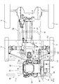
- the left projecting end portion of the output shaft 70 includes not only the discharge fan 91 but also a plurality of output pulleys 92 and 93 for transmitting rotational force (in the embodiment, 2) are provided.
- the output pulleys 92 and 93 are configured to rotate together with the discharge fan 91 by the rotation of the output shaft 70.
- the output pulleys 92 and 93 are arranged so as to be distributed in the front and rear directions of the output shaft 70 with the discharge fan 91 interposed therebetween.
- the output pulley 92 closer to the engine 5 is a first output pulley 92 for transmitting rotational force to a generator 94 (described later in detail), and the output pulley 93 far from the engine is connected to the transmission case 6 from the transmission case 6.
- This is a second output pulley 93 for transmitting a rotational force to a mission input shaft 97 (details will be described later) projecting to the left outer side.
- the generator 94 is arranged on the opposite side (rear side in the embodiment) of the vertical pipe portion 87b of the exhaust pipe 87 with the left protruding end portion of the output shaft 70 interposed therebetween.
- the generator 94 is attached to a fixed bracket 95 that is bolted to the left rear side of the left side surface of the engine 5 with respect to the left protruding end portion of the output shaft 70 and below the horizontal cover body 89.
- an appropriate space is left and right between the left side surface of the engine 5 and the generator 94.
- An auxiliary machine input pulley 94 a is provided on the side of the generator 94 that faces the left side of the engine 5.
- a transmission belt 96 is wound around a first output pulley 92 on the output shaft 70 side and an auxiliary machine input pulley 94a on the generator 94 side.
- a rotational force is transmitted from the engine 5 to the generator 94 via the pulley 92 and the belt 96 transmission system, and the generator 94 generates power. Since the generator 94 is attached to the left side surface of the engine 5 via the fixed bracket 95, it is included in the same vibration system as the engine 5. For this reason, the load concerning generator 94 itself can be reduced and the possibility of a deformation
- a mission input pulley 98 is provided on the mission input shaft 97 projecting leftward from the mission case 6.
- a transmission belt 99 is wound around the second output pulley 93 on the output shaft 70 side and the mission input pulley 98 on the mission case 6 side.
- a rotational force is transmitted from the engine 5 to the transmission case 6 via the pulleys 93 and 98 and the belt 99 transmission system.
- a mission cooling fan 100 for air cooling of the mission case 6 is provided on the outer left side of the mission output shaft 97 from the mission input pulley 98.
- the mission cooling fan 100 is configured to rotate together with the mission input pulley 98 by the rotational force transmitted through the pulleys 93 and 98 and the belt 99 transmission system.
- the exhaust fan 91, the first and second output pulleys 92 and 93, the generator 94 and the transmission belts 96 and 99 are disposed inside the shielding cover 88 on the left side surface of the engine 5. .
- the pulleys 92 and 93 and the belts 96 and 99 and the generator 94 are compactly arranged inside the shielding cover 88 on the left side surface of the engine 5. The heat around the surface can be discharged smoothly via the lower exhaust passage 86.
- the exhaust air is blown onto the pulleys 92 and 93 and the belts 96 and 99 and the generator 94 to cool them, the heat deterioration of the pulleys 92 and 93 and the belts 96 and 99 and the generator 94 can be suppressed. To improve performance.
- the outer diameter of the discharge fan 91 is configured to be larger than the output pulleys 92 and 93. For this reason, when exhaust air is exhausted by the rotation of the exhaust fan 91 via the lower exhaust path 86, the presence of the output pulleys 92 and 93 is less likely to be an obstacle. Emission efficiency can be maintained well.
- Each output pulley 92, 93 is configured to have a smaller diameter as it is closer to the engine 5. For this reason, when the heat of the left side surface of the engine 5 is taken away by the rotation of the exhaust fan 91, the influence of the presence of the first output pulley 92 closer to the engine 5 can be reduced.
- the output pulleys 92 and 93 and the exhaust fan 91 can be arranged in a compact manner at the left projecting end portion of the output shaft 70 while suppressing heat deterioration of the pulleys 92 and 93 and the belts 96 and 99. Expansion of the left-right width of the front bonnet 11 covering this can be suppressed.
- a tension applying member 101 that tensions the transmission belt 99 is disposed between the second output pulley 93 on the output shaft 70 side and the transmission output pulley 98.
- the tension applying member 101 includes a tension pulley 102 that comes into contact with the transmission belt 99 from below.
- the tension pulley 102 is pivotally supported on the free end side of a tension arm 103 that is connected to the left side of the engine stand 57 so as to be rotatable up and down.
- the tension arm 103 is pulled in the upward rotation direction by the biasing spring 104, and the tension pulley 102 is always pressed against the transmission belt 99 from below.
- the urging spring 104 is mounted between a swing arm 106 erected on the boss portion 105 on the base end side of the tension arm 103 and a support plate 107 projecting on the left side of the engine stand 57. .
- the tension applying member 101 when the tension applying member 101 is provided on the engine stand 57 on which the engine 5 is mounted, the tension applying member 101 is included in the same vibration system as the engine 5. Can be reduced. As a result, the risk of deformation or breakage of the tension applying member 101 can be suppressed. Further, the vibration of the tension applying member 101 follows the vibration of the engine 5, and there is an advantage that the transmission belt 99 can be easily maintained in a state where an appropriate tension is applied.
- the generator 94 is positioned between the second output pulley 93 and the mission output pulley 98 in a state where the engine 5 and the mission case 6 are arranged side by side. The space between the engine 5 and the mission case 6 is also effectively used.
- the engine 5 of the embodiment is bolted to an engine stand 57 supported by both front and rear base frames 56 via a plurality of vibration isolating rubbers 58.
- the engine stand 57 is formed with a vertically penetrating through hole 108 that faces the bottom surface of the engine 5.
- a rib groove 109 formed on the bottom surface of the engine 5 faces the hole 108 of the engine stand 57.
- the engine 5 is arranged on the engine stand 57 so as to be shifted (to the right side) from the punch hole 108 so that the cooling air flows from the punch hole 108 toward the exhaust fan 91 on the left side of the engine.
- a part of the hole 108 is opened up and down without covering the entire hole 108 of the engine stand 57 with the bottom surface of the engine 5.
- the first output pulley 92 and the transmission belt 96 on the left side of the engine 5 can be seen in a part of the hole 108.
- the cooling air taken in by the rotation of the suction fan 71 can be blown to the bottom surface of the engine 5.
- the engine oil can be positively cooled to prevent an excessive increase in engine oil temperature. Combined with the cooling efficiency of the first and second oil coolers 78 and 79, the engine oil is effectively cooled, and the heat balance of the engine 5 can be maintained well.
- the engine 5 is arranged on the engine stand 57 so as to be displaced from the hole 108 so that the cooling air flows from the hole 108 toward the exhaust fan 91. Cooling air can be sent from the bottom side to the left side via the punch hole 108. For this reason, a relatively low temperature cooling air can be mixed with the exhaust air around the left side surface of the engine 5 to lower the temperature of the exhaust air itself, and the thermal environment on the left side surface of the engine 5 can be greatly improved.
- the engine 5 mounted on the traveling machine body 2, the transmission case 6 for shifting the power of the engine 5 and transmitting it to the traveling units 3 and 4 of the traveling machine body 2, and the traveling machine body 2 And a seedling planting device 23 mounted on the engine 5, wherein a suction fan 71 for engine air cooling is provided on one side of the engine 5.
- An exhaust pipe 87 (87b) communicating with the exhaust system of the engine 5 is extended on one side of the other side opposite to the output shaft 70 protruding from the other side, and a generator 94 is arranged on the other side. Therefore, the exhaust pipe 87 (87b) and the generator 94 are distributed on both sides of the output shaft 70 so that heat from the exhaust pipe 87 (87b) is applied to the generator 94.
- the exhaust pipe 87 (87b) and the generator 94 can be arranged together in a compact manner on the other side surface of the engine 5 while suppressing adverse effects.
- the transmission belt 99 wound around the output pulley 93 fixed to the output shaft 70, the transmission input pulley 98 fixed to the transmission input shaft 97 of the transmission case 6, and the transmission belt 99 are tensioned. Since the tension applying member 101 is further provided and the tension applying member 101 and the generator 94 are positioned between the output pulley 93 and the mission input pulley 98, the engine 5 and the mission case 6 are provided.
- the arrangement of the pulleys 93 and 98 and the belt 99 transmission system to the transmission case 6 can be made compact by making effective use of the space between them.
- the engine 5 is mounted on an engine base 57 attached to the traveling machine body 2 via a vibration isolation member 58, the tension applying member 101 is attached to the engine base 57, and the generator 94 is The tension applying member 101 and the generator 94 are included in the same vibration system as the engine 5 because the tension applying member 101 and the generator 94 are attached to the fixed bracket 95 fastened to the other side surface of the engine 5. For this reason, the load concerning the said tension
- the engine 5 mounted on the traveling machine body 2, the transmission case 6 that shifts the power of the engine 5 and transmits it to the traveling units 3, 4 of the traveling machine body 2, and the traveling machine body 2
- a rice transplanter 1 having a suction fan 71 for air cooling of the engine provided on one side surface of the engine 5, and a pair of left and right constituting the traveling machine body 2.
- the engine 5 is arranged between the body frames 50 so as to protrude below the body frames 50, and the other side of the engine 5 opposite to the suction fan 71 is disposed on the body body.
- a ventilation duct 84 that allows cooling air from the suction fan 71 to pass therethrough is disposed above the frame 50, and an upper exhaust passage 85 of the engine 5 is formed by the ventilation duct 84.
- the presence of the ventilation duct 84 removes the heat of the engine 5 and warms it. It is possible to suppress the diffused exhaust air from diffusing in the engine room. In addition, the exhaust air can be prevented from staying back in the engine room, and the exhaust air can be smoothly discharged from the upper air exhaust passage 85, and the exhaust air exhaust efficiency can be improved. Also, the exhaust path of the engine 5 is divided into two parts, the upper exhaust path 85 and the lower exhaust path 86, so that the exhaust air can be efficiently discharged out of the engine room. Efficiency can be maintained in a good state.
- a cleaner case 76 that houses an air cleaner is disposed on the upper surface of the engine 5 at an appropriate distance in the vertical direction, and an upper ventilation path 77 between the cleaner case 76 and the engine 5 is provided in the ventilation duct 84. Since the cooling fan 71 is rotated, the cooling air is taken into the vicinity of the upper surface of the engine 5 to cool the periphery of the upper surface of the engine 5. Then, the exhausted air warmed by removing the heat around the upper surface of the engine 5 can be discharged smoothly via the ventilation duct 84. Therefore, the cooling efficiency of the engine 5 is improved.
- an output shaft 70 protruding from the other side surface of the engine 5 is located at a position overlapping the body frame 50 on the other side surface of the engine 5 in a side view, and is an exhaust pipe communicating with the exhaust system of the engine 5.
- 87 is formed in an L-shape that crosses between the ventilation duct 84 and the output shaft 70 and then extends vertically while sandwiching the output shaft 70, and the other side surface of the engine 5. Since the shielding cover 88 surrounding the exhaust pipe 87 is provided, the presence of the shielding cover 88 can suppress the heat generated from the exhaust pipe 87 from diffusing in the engine room.
- a rice planter 1 provided with a suction fan 71 for engine air cooling provided on one side of the engine 5, the seedling planting device 23 being mounted, and the suction fan 71 of the engine 5
- a discharge fan 91 is provided separately from the suction fan 71 on the other side surface on the opposite side, so that cooling air is blown to the engine 5 by the suction fan 71 on the one side surface of the engine 5,
- the exhaust fan 91 on the other side of the engine 5 rotates to take away the heat of the engine 5 and exhaust the warm exhaust air outside the engine room. It becomes Rukoto. Therefore, the cooling air intake effect of the suction fan 71 and the exhaust air discharge effect of the exhaust fan 91 are combined, and the cooling efficiency of the engine 5 can be significantly improved.
- the output shaft 70 of the engine 5 is provided with output pulleys 92 and 93 for transmitting rotational force together with the exhaust fan 91, and the exhaust fan 91 and the output pulleys 92 and 93 are connected to the output shaft 70. Therefore, the output pulleys 92 and 93 can be cooled using the rotation of the exhaust fan 91 to cool the output pulleys 92 and 93. For this reason, while the discharge fan 91 and the output pulleys 92 and 93 are arranged in a compact manner, thermal degradation of the output pulleys 92 and 93 can be suppressed, and durability of these can be improved. Since the arrangement of the exhaust fan 91 and the output pulleys 92 and 93 can be made compact, it is possible to suppress an increase in the lateral width of the engine 5 and thus the engine room.
- the outer diameter of the exhaust fan 91 is larger than that of the output pulleys 92 and 93, when the exhaust air is exhausted by the rotation of the exhaust fan 91, Existence is less likely to get in the way, and the exhaust efficiency of exhausted air due to the rotation of the exhaust fan 91 can be maintained well.
- a plurality of the output pulleys 92 and 93 are provided, and the plurality of output pulleys 92 and 93 are configured to have a smaller diameter as they approach the engine 5. When the heat on the side surface is taken away, the influence of the output pulley 92 closer to the engine 5 can be reduced.
- the engine 5 mounted on the traveling machine body 2, the transmission case 6 that shifts the power of the engine 5 and transmits it to the traveling units 3, 4 of the traveling machine body 2, and the traveling machine body 2
- a rice planting machine 1 provided with a suction planting fan 71 for air cooling the engine 5 on one side of the engine 5, and a vibration isolating member 58 provided on the traveling machine body 2.
- the engine 5 is mounted on an engine base 57 attached via a through hole, and the engine base 57 is formed with a hole 108 facing the bottom surface of the engine 5.
- the taken cooling air can be blown to the bottom surface of the engine 5. Therefore, the engine oil inside the engine 5 can be actively cooled to suppress an excessive increase in the engine oil temperature, and the heat balance of the engine 5 can be maintained well.
- a discharge fan is provided on the other side of the engine 5 opposite to the suction fan 71, separately from the suction fan, and cooling air flows from the through hole toward the discharge fan.
- the exhaust fan 91 rotates and passes through the hole 108 from the bottom surface side to the other side surface of the engine 5.
- the cooling air can be sent in. For this reason, a relatively low temperature cooling air can be mixed with the exhaust air around the other side surface of the engine 5 to lower the temperature of the exhaust air itself, and the thermal environment on the other side surface of the engine 5 can be greatly improved.
- the engine 5 and the engine stand 57 are arranged between the pair of left and right body frames 50 constituting the traveling body 2 so as to protrude below the both body frames 50, the engine Cooling air can be taken in smoothly from the bottom side of 5.
- the engine 5 mounted on the traveling machine body 2, the transmission case 6 that shifts the power of the engine 5 and transmits it to the traveling units 3, 4 of the traveling machine body 2, and the traveling machine body 2
- a rice transplanter 1 having a suction fan 71 for air cooling of the engine provided on one side surface of the engine 5, and a pair of left and right constituting the traveling machine body 2.
- the engine 5 is disposed between the fuselage frames 50 so as to protrude below the fuselage frames 50.
- the suction fan 71 is located below the front bonnet 11 that covers the engine 5 from above. Since the oil cooler 79 is disposed opposite to the air cooler 79, the oil cooler 79 is cooled by the rotation of the suction fan 71 and is mainly cooled from below the body frame 50. By the wind, it will be cooled prior to the engine 5. Therefore, the cooling efficiency of the oil cooler 79 can be improved without using a cooling fan dedicated to the oil cooler 79. This also contributes to the downsizing of the oil cooler 79.
- an electrical component 83 disposed above the oil cooler 79 faces a distribution port 75 formed on the lower side of the front bonnet 11 and is provided in the front bonnet 11 so as to surround the engine 5. Since the oil cooler 79 and the electrical component 83 are supported by the bonnet frame 80, the cooling air passing through the circulation port 75 by the rotation of the suction fan 71 is blown to the electrical component 83, and the electrical component 83 will be cooled. With the cooling air from the circulation port 75, the temperature rise of the electrical component 83 arranged around the engine 5 can be suppressed. The adverse effect on the electrical component 83 due to the heat of the engine 5 can be avoided.
- the support structure between the oil cooler 79 and the electrical component 83 can be simplified using the bonnet frame 80.
- the engine 5 mounted on the traveling machine body 2, the transmission case 6 that shifts the power of the engine 5 and transmits it to the traveling units 3, 4 of the traveling machine body 2, and the traveling machine body 2
- the rice transplanter 1 is provided with a seedling planting device 23 attached thereto, and a suction fan 71 for engine air cooling is provided on one side of the engine 5, and the engine 5 moves the output shaft 70 in the left-right direction.
- a discharge fan 91 is provided on the other side of the engine 5 opposite to the suction fan 71, separately from the suction fan 71.
- the shielding cover 88 that surrounds the fan 91 is provided on the other side surface of the engine 5, the cooling air intake effect of the suction fan 71 and the exhaust air discharge effect of the exhaust fan 91 are combined, The cooling efficiency of the gin 5 In addition to being able to significantly improved by the presence of the shielding cover 88, the heat near the engine 5 left side can be prevented from diffusing in the engine room.
- the output shaft 70 of the engine 5 is provided with output pulleys 92 and 93 for transmitting rotational force together with the exhaust fan 91, and the exhaust is disposed inside the shielding cover 88 on the other side of the engine 5. Since the fan 91, the generator 94 and the pulleys 92, 93 and the belt 96, 99 transmission system are arranged, the exhaust fan is arranged while the pulleys 92, 93, the belt 96, 99 transmission system and the generator 94 are arranged in a compact manner. By rotating 91, heat around the left side of the engine 5 can be discharged smoothly.
- the exhaust fan 91 is rotated to blow and cool the pulleys 92 and 93 and the belts 96 and 99 and the generator 94, the pulleys 92 and 93 and the belts 96 and 99 Thermal deterioration of the generator 94 can be suppressed, and the durability of these can be improved.
Landscapes
- Life Sciences & Earth Sciences (AREA)
- Engineering & Computer Science (AREA)
- Soil Sciences (AREA)
- Environmental Sciences (AREA)
- Chemical & Material Sciences (AREA)
- Combustion & Propulsion (AREA)
- Transportation (AREA)
- Mechanical Engineering (AREA)
- Cooling, Air Intake And Gas Exhaust, And Fuel Tank Arrangements In Propulsion Units (AREA)
- Arrangement Of Transmissions (AREA)
- Cylinder Crankcases Of Internal Combustion Engines (AREA)
- Transplanting Machines (AREA)
Priority Applications (3)
| Application Number | Priority Date | Filing Date | Title |
|---|---|---|---|
| IN7463DEN2014 IN2014DN07463A (enExample) | 2012-03-27 | 2013-03-19 | |
| CN201380016706.0A CN104220726B (zh) | 2012-03-27 | 2013-03-19 | 插秧机 |
| KR1020147025574A KR20140138719A (ko) | 2012-03-27 | 2013-03-19 | 이앙기 |
Applications Claiming Priority (2)
| Application Number | Priority Date | Filing Date | Title |
|---|---|---|---|
| JP2012-070641 | 2012-03-27 | ||
| JP2012070641A JP5997469B2 (ja) | 2012-03-27 | 2012-03-27 | 田植機 |
Publications (1)
| Publication Number | Publication Date |
|---|---|
| WO2013146473A1 true WO2013146473A1 (ja) | 2013-10-03 |
Family
ID=49259729
Family Applications (1)
| Application Number | Title | Priority Date | Filing Date |
|---|---|---|---|
| PCT/JP2013/057835 Ceased WO2013146473A1 (ja) | 2012-03-27 | 2013-03-19 | 田植機 |
Country Status (5)
| Country | Link |
|---|---|
| JP (1) | JP5997469B2 (enExample) |
| KR (1) | KR20140138719A (enExample) |
| CN (1) | CN104220726B (enExample) |
| IN (1) | IN2014DN07463A (enExample) |
| WO (1) | WO2013146473A1 (enExample) |
Families Citing this family (3)
| Publication number | Priority date | Publication date | Assignee | Title |
|---|---|---|---|---|
| JP6687848B2 (ja) * | 2016-05-20 | 2020-04-28 | 井関農機株式会社 | 作業車両 |
| KR102053017B1 (ko) * | 2018-02-05 | 2019-12-06 | 동양물산기업 주식회사 | 이식기 프레임 |
| JP7224236B2 (ja) * | 2019-04-26 | 2023-02-17 | 株式会社クボタ | 水田作業機 |
Citations (5)
| Publication number | Priority date | Publication date | Assignee | Title |
|---|---|---|---|---|
| JPH1182048A (ja) * | 1997-09-08 | 1999-03-26 | Kubota Corp | 作業機の原動部構造 |
| JP2000006672A (ja) * | 1998-06-25 | 2000-01-11 | Kubota Corp | 水田作業機の原動部構造 |
| JP2000326738A (ja) * | 1999-05-18 | 2000-11-28 | Kubota Corp | 水田作業機の原動部 |
| JP2001199251A (ja) * | 2000-01-19 | 2001-07-24 | Kubota Corp | 作業車の原動部冷却構造 |
| JP3426387B2 (ja) * | 1995-02-16 | 2003-07-14 | ヤンマー農機株式会社 | 田植機 |
Family Cites Families (7)
| Publication number | Priority date | Publication date | Assignee | Title |
|---|---|---|---|---|
| JPS56159622U (enExample) * | 1980-04-26 | 1981-11-28 | ||
| CN1073338C (zh) * | 1996-12-26 | 2001-10-24 | 株式会社久保田 | 乘式插秧机 |
| JP3705209B2 (ja) * | 2002-01-17 | 2005-10-12 | 井関農機株式会社 | コンバインの通気構造 |
| CN201013513Y (zh) * | 2007-02-28 | 2008-01-30 | 天津内燃机研究所 | 带辅助冷却装置的风冷发动机 |
| KR100974278B1 (ko) * | 2008-03-18 | 2010-08-06 | 볼보 컨스트럭션 이키프먼트 홀딩 스웨덴 에이비 | 건설장비의 엔진실 |
| KR101717161B1 (ko) * | 2009-11-10 | 2017-03-16 | 얀마 가부시키가이샤 | 승용형 농작업기 |
| CN201963385U (zh) * | 2011-01-30 | 2011-09-07 | 钟群明 | 一种小型发电机组的风冷结构 |
-
2012
- 2012-03-27 JP JP2012070641A patent/JP5997469B2/ja not_active Expired - Fee Related
-
2013
- 2013-03-19 WO PCT/JP2013/057835 patent/WO2013146473A1/ja not_active Ceased
- 2013-03-19 KR KR1020147025574A patent/KR20140138719A/ko not_active Ceased
- 2013-03-19 CN CN201380016706.0A patent/CN104220726B/zh not_active Expired - Fee Related
- 2013-03-19 IN IN7463DEN2014 patent/IN2014DN07463A/en unknown
Patent Citations (5)
| Publication number | Priority date | Publication date | Assignee | Title |
|---|---|---|---|---|
| JP3426387B2 (ja) * | 1995-02-16 | 2003-07-14 | ヤンマー農機株式会社 | 田植機 |
| JPH1182048A (ja) * | 1997-09-08 | 1999-03-26 | Kubota Corp | 作業機の原動部構造 |
| JP2000006672A (ja) * | 1998-06-25 | 2000-01-11 | Kubota Corp | 水田作業機の原動部構造 |
| JP2000326738A (ja) * | 1999-05-18 | 2000-11-28 | Kubota Corp | 水田作業機の原動部 |
| JP2001199251A (ja) * | 2000-01-19 | 2001-07-24 | Kubota Corp | 作業車の原動部冷却構造 |
Also Published As
| Publication number | Publication date |
|---|---|
| KR20140138719A (ko) | 2014-12-04 |
| CN104220726A (zh) | 2014-12-17 |
| IN2014DN07463A (enExample) | 2015-04-24 |
| JP5997469B2 (ja) | 2016-09-28 |
| JP2013204423A (ja) | 2013-10-07 |
| CN104220726B (zh) | 2017-09-19 |
Similar Documents
| Publication | Publication Date | Title |
|---|---|---|
| JP2001199251A (ja) | 作業車の原動部冷却構造 | |
| JP3862674B2 (ja) | 乗用型移植機 | |
| JP5997469B2 (ja) | 田植機 | |
| WO2013146476A1 (ja) | 田植機 | |
| WO2013146475A1 (ja) | 田植機 | |
| JP5829963B2 (ja) | 田植機 | |
| JP5288290B2 (ja) | 作業車輌の原動部構造 | |
| JP5844192B2 (ja) | 田植機 | |
| JP5964100B2 (ja) | 田植機 | |
| JP5844191B2 (ja) | 田植機 | |
| JP6015960B2 (ja) | コンバイン | |
| JP5844190B2 (ja) | 田植機 | |
| JP2010168043A (ja) | 田植機 | |
| JP6032569B2 (ja) | 作業車輌の原動部構造 | |
| TWI569715B (zh) | 作業車輛的原動部構造 | |
| JP3599479B2 (ja) | 乗用型移植機 | |
| JP5765817B2 (ja) | 田植機 | |
| JP5737522B2 (ja) | 作業車両の原動部構造 | |
| JP2014134104A (ja) | 作業車輌 | |
| JP5513363B2 (ja) | 作業機 | |
| JP7243667B2 (ja) | 作業車両 | |
| JP6150169B2 (ja) | 作業車輌の原動部構造 | |
| JP5527553B2 (ja) | コンバイン | |
| JP5174075B2 (ja) | 乗用型作業機 | |
| JP4462573B2 (ja) | バーチカルエンジン搭載作業車の冷却機構 |
Legal Events
| Date | Code | Title | Description |
|---|---|---|---|
| 121 | Ep: the epo has been informed by wipo that ep was designated in this application |
Ref document number: 13770000 Country of ref document: EP Kind code of ref document: A1 |
|
| ENP | Entry into the national phase |
Ref document number: 20147025574 Country of ref document: KR Kind code of ref document: A |
|
| NENP | Non-entry into the national phase |
Ref country code: DE |
|
| 122 | Ep: pct application non-entry in european phase |
Ref document number: 13770000 Country of ref document: EP Kind code of ref document: A1 |