WO2013146476A1 - 田植機 - Google Patents
田植機 Download PDFInfo
- Publication number
- WO2013146476A1 WO2013146476A1 PCT/JP2013/057838 JP2013057838W WO2013146476A1 WO 2013146476 A1 WO2013146476 A1 WO 2013146476A1 JP 2013057838 W JP2013057838 W JP 2013057838W WO 2013146476 A1 WO2013146476 A1 WO 2013146476A1
- Authority
- WO
- WIPO (PCT)
- Prior art keywords
- engine
- fan
- exhaust
- machine body
- output
- Prior art date
Links
Images


Classifications
-
- A—HUMAN NECESSITIES
- A01—AGRICULTURE; FORESTRY; ANIMAL HUSBANDRY; HUNTING; TRAPPING; FISHING
- A01C—PLANTING; SOWING; FERTILISING
- A01C11/00—Transplanting machines
- A01C11/003—Transplanting machines for aquatic plants; for planting underwater, e.g. rice
-
- B—PERFORMING OPERATIONS; TRANSPORTING
- B60—VEHICLES IN GENERAL
- B60K—ARRANGEMENT OR MOUNTING OF PROPULSION UNITS OR OF TRANSMISSIONS IN VEHICLES; ARRANGEMENT OR MOUNTING OF PLURAL DIVERSE PRIME-MOVERS IN VEHICLES; AUXILIARY DRIVES FOR VEHICLES; INSTRUMENTATION OR DASHBOARDS FOR VEHICLES; ARRANGEMENTS IN CONNECTION WITH COOLING, AIR INTAKE, GAS EXHAUST OR FUEL SUPPLY OF PROPULSION UNITS IN VEHICLES
- B60K11/00—Arrangement in connection with cooling of propulsion units
- B60K11/06—Arrangement in connection with cooling of propulsion units with air cooling
-
- B—PERFORMING OPERATIONS; TRANSPORTING
- B60—VEHICLES IN GENERAL
- B60K—ARRANGEMENT OR MOUNTING OF PROPULSION UNITS OR OF TRANSMISSIONS IN VEHICLES; ARRANGEMENT OR MOUNTING OF PLURAL DIVERSE PRIME-MOVERS IN VEHICLES; AUXILIARY DRIVES FOR VEHICLES; INSTRUMENTATION OR DASHBOARDS FOR VEHICLES; ARRANGEMENTS IN CONNECTION WITH COOLING, AIR INTAKE, GAS EXHAUST OR FUEL SUPPLY OF PROPULSION UNITS IN VEHICLES
- B60K5/00—Arrangement or mounting of internal-combustion or jet-propulsion units
- B60K5/04—Arrangement or mounting of internal-combustion or jet-propulsion units with the engine main axis, e.g. crankshaft axis, transversely to the longitudinal centre line of the vehicle
-
- B—PERFORMING OPERATIONS; TRANSPORTING
- B60—VEHICLES IN GENERAL
- B60K—ARRANGEMENT OR MOUNTING OF PROPULSION UNITS OR OF TRANSMISSIONS IN VEHICLES; ARRANGEMENT OR MOUNTING OF PLURAL DIVERSE PRIME-MOVERS IN VEHICLES; AUXILIARY DRIVES FOR VEHICLES; INSTRUMENTATION OR DASHBOARDS FOR VEHICLES; ARRANGEMENTS IN CONNECTION WITH COOLING, AIR INTAKE, GAS EXHAUST OR FUEL SUPPLY OF PROPULSION UNITS IN VEHICLES
- B60K5/00—Arrangement or mounting of internal-combustion or jet-propulsion units
- B60K5/12—Arrangement of engine supports
- B60K5/1208—Resilient supports
- B60K5/1216—Resilient supports characterised by the location of the supports relative to the motor or to each other
-
- B—PERFORMING OPERATIONS; TRANSPORTING
- B60—VEHICLES IN GENERAL
- B60Y—INDEXING SCHEME RELATING TO ASPECTS CROSS-CUTTING VEHICLE TECHNOLOGY
- B60Y2200/00—Type of vehicle
- B60Y2200/20—Off-Road Vehicles
- B60Y2200/22—Agricultural vehicles
Definitions
- the present invention relates to a rice transplanter having a seedling stand and a plurality of planting claws and continuously performing seedling planting operations.
- the present invention has been made in view of the above situation, and provides a rice transplanter in which peripheral parts such as cooling system parts and power transmission system parts are efficiently and compactly arranged around the engine while improving cooling efficiency. Is a technical issue.
- the invention of claim 1 includes an engine mounted on a traveling machine body, a transmission case that shifts the power of the engine and transmits it to a traveling part of the traveling machine body, and a seedling planting device mounted on the traveling machine body.
- a rice transplanter provided with a suction fan for air cooling of the engine on one side of the engine, the other side of the engine opposite to the suction fan separately from the suction fan The exhaust fan is provided.
- the output shaft of the engine is provided with an output pulley for transmitting a rotational force together with the exhaust fan, and the exhaust fan and the output pulley are , And are configured to rotate together with the rotation of the output shaft.
- the outer diameter of the exhaust fan is configured to be larger than the output pulley.
- a plurality of the output pulleys are provided, and the plurality of output pulleys are configured to have a smaller diameter as they approach the engine.
- a shielding cover surrounding the exhaust fan is provided on the other side of the engine.
- the output shaft of the engine is provided with an output pulley for transmitting a rotational force together with the exhaust fan, and the shielding of the other side surface of the engine.
- the exhaust fan, generator, pulley, and belt transmission system are arranged inside the cover.
- the engine includes an engine mounted on a traveling machine body, a transmission case that shifts the power of the engine and transmits it to a traveling unit of the traveling machine body, and a seedling planting device that is mounted on the traveling machine body.
- the engine is provided with a suction fan for air cooling on one side of the engine, and the other side of the engine opposite to the suction fan is discharged separately from the suction fan. Since the fan is provided, not only the engine is forcedly cooled by blowing cooling air to the engine by the suction fan on one side of the engine, but also by the rotation of the exhaust fan on the other side of the engine. Then, the exhaust air warmed by taking the heat of the engine is discharged out of the engine room. Accordingly, the cooling air intake effect of the suction fan and the exhaust air discharge effect of the exhaust fan can be combined to significantly improve the cooling efficiency of the engine.
- the output shaft of the engine is provided with an output pulley for transmitting rotational force together with the exhaust fan, and the exhaust fan and the output pulley rotate together by the rotation of the output shaft.
- the output pulley can be cooled by blowing air to the output pulley using the rotation of the exhaust fan.
- positioning the said exhaust fan and the said output pulley compactly, the thermal deterioration of the said output pulley can be suppressed and these durability improvement can be aimed at. Since the arrangement of the exhaust fan and the output pulley can be made compact, it is possible to suppress an increase in the lateral width of the engine and thus the engine room.
- the outer diameter of the exhaust fan is configured to be larger than the output pulley, the presence of the output pulley is present when exhaust air is exhausted by the rotation of the exhaust fan. There is little possibility of getting in the way, and the exhaust efficiency of exhaust air by the rotation of the exhaust fan can be maintained well.
- a plurality of the output pulleys are provided, and the plurality of output pulleys are configured to have a smaller diameter as they approach the engine. When taking heat away, the influence of the output pulley closer to the engine can be reduced.
- the shielding cover that surrounds the exhaust fan is provided on the other side surface of the engine, the cooling air intake effect of the suction fan and the exhaust air exhaust effect of the exhaust fan are combined.
- the presence of the shielding cover can suppress the diffusion of heat around the left side of the engine in the engine room.
- the output shaft of the engine is provided with an output pulley for transmitting rotational force together with the exhaust fan, and the exhaust fan is disposed on the inner side of the shielding cover on the other side surface of the engine. Since the generator, the pulley, and the belt transmission system are arranged, the heat around the left side of the engine can be smoothly discharged by the rotation of the exhaust fan while the pulley, the belt transmission system, and the generator are arranged in a compact manner. In addition, since the exhaust fan blows and cools the pulley and belt transmission system and the generator by rotating the exhaust fan, thermal deterioration of the pulley and belt transmission system and the generator can be suppressed, and the durability of these can be improved. I can plan.
- the left side in the traveling direction of the traveling machine body 2 is simply referred to as the left side
- the right side in the traveling direction is also simply referred to as the right side.
- the rice transplanter 1 includes a traveling machine body 2 supported by a pair of left and right front wheels 3 and a pair of left and right rear wheels 4 as a traveling unit.
- An engine 5 is mounted on the front part of the traveling machine body 2, and the power from the engine 5 is transmitted to the rear transmission case 6 to drive the front wheels 3 and the rear wheels 4 so that the vehicle travels forward and backward.
- a front axle case 7 projects from the left and right sides of the transmission case 6, and the front wheels 3 are attached to a front axle extending from the front axle case 7 to the left and right so as to be steerable.
- a cylindrical frame 8 is projected behind the transmission case 6, a rear axle case 9 is fixed to the rear end side of the cylindrical frame 8, and the rear wheel 4 is attached to a rear axle that extends outward from the rear axle case 9 to the left and right. Yes.
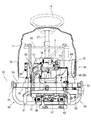
- an operator boarding work step (vehicle body cover) 10 is provided on the upper surface side of the front part and the central part of the traveling machine body 2.
- a front bonnet 11 is disposed above the front part of the work step 10, and the engine 5 is installed inside the front bonnet 11.
- a traveling speed change pedal 12 for stepping operation is disposed on the upper side of the work step 10 on the rear side of the front bonnet 11.
- a steering handle 14, a traveling main transmission lever 15, and a work lever 16 are provided in the driving operation unit 13 on the upper surface side of the rear portion of the front bonnet 11.
- a steering seat 18 is disposed via a seat frame 17 behind the front bonnet 11 on the upper surface of the work step 10.
- left and right spare seedling platforms 24 are provided on the left and right sides of the front bonnet 11 with the operation step 10 interposed therebetween.
- the link frame 19 is erected at the rear end of the traveling machine body 2.
- a seedling planting device 23 for 8-row planting is connected to the link frame 19 via a parallel link mechanism 22 including a lower link 20 and a top link 21 so as to be movable up and down.
- the operator gets on the work step 10 from the boarding / alighting step 25 on the side of the work step 10 and drives the seedling planting device 23 to move the seedling planting device 23 and move the seedling planting in the field while moving in the field by the driving operation. Perform work (rice planting work).
- the operator replenishes the seedling planting device 23 with a seedling mat on the preliminary seedling mounting table 24 as needed.
- the seedling planting device 23 includes a planting input case 26 to which power is transmitted from the engine 5 via the mission case 6, and an 8-strip 4 connected to the planting input case 26.
- the seedling planting mechanism 28 is provided with a rotary case 31 having two planting claws 30 for one line. Two planted rotary cases 31 are arranged in the planting transmission case 27. By one rotation of the rotary case 31, the two planting claws 30 cut and grasp one seedling each, and plant it on the field leveled by the float 32.
- the power from the engine 5 via the transmission case 6 is transmitted not only to the front wheels 3 and the rear wheels 4, but also to the planting input case 26 of the seedling planting device 23.
- the power from the transmission case 6 toward the seedling planting device 23 is once transmitted to an inter-plant transmission case (not shown) provided on the upper right side of the rear axle case 9, and the motive power is transmitted from the inter-plant transmission case to the planting input case 26.
- the seedling planting mechanism 28 and the seedling mount 29 are driven by the transmitted power.
- the inter-strain shifting case includes an inter-strain shifting mechanism that switches between planted seedlings to, for example, sparse planting, standard planting, or dense planting, and a PTO clutch that interrupts power transmission to the seedling planting device 23. Is built-in.
- a side marker 33 is provided on the left and right outside of the seedling planting device 23.
- the side marker 33 includes a marker ring body 34 for muscle pulling and a marker arm 35 that pivotally supports the marker ring body 34 so as to be rotatable.
- the base end side of each marker arm 35 is pivotally supported on the left and right outer sides of the seedling planting device 23 so as to be rotatable left and right.
- the side marker 33 is moved away from the surface by raising the marker wheel body 34 based on the operation posture of the operation lever 16 in the driving operation unit 13 and forming a trajectory as a reference in the next process by landing on the surface.
- the non-working posture is configured to be rotatable.
- the traveling machine body 2 includes a pair of left and right machine body frames 50 extending in the front-rear direction.
- Each body frame 50 is divided into a front frame 51 and a rear frame 52.
- the rear end portion of the front frame 51 and the front end portion of the rear frame 52 are welded and fixed to a laterally long intermediate connection frame 53.
- the front ends of the pair of left and right front frames 51 are fixed to the front frame 54 by welding.
- the rear end sides of the left and right rear frames 52 are fixed to the rear frame 55 by welding.
- the front frame 54, the left and right front frames 51, and the intermediate connection frame 53 are configured in a square frame shape in plan view.
- the intermediate connection frame 53, the left and right rear frames 52, and the rear frame 55 are also configured in a square frame shape in plan view.
- the front portions of the left and right front frames 51 are connected by two front and rear base frames 56.
- Each of the base frames 56 is formed in a shape that is bent in a U shape so that an intermediate portion thereof is positioned lower than the left and right front frames 51.
- the left and right ends of each base frame 56 are fixed by welding to the corresponding front frames 51.
- the engine 5 is mounted on and supported by the front and rear base frames 56 through a substantially flat engine stand 57 and a plurality of vibration isolating rubbers 58 as vibration isolating members.
- the front base frame 56 is connected to the front frame 54 via a front relay frame 59 fixedly welded thereto.
- the rear base frame 56 is connected to the front portion of the transmission case 6 via the rear relay bracket 60.
- the engine 5 of the embodiment is a 4-stroke V-type 2-cylinder gasoline engine.
- the rear portions of the left and right front frames 51 are connected to a front axle case 7 protruding from the left and right sides of the mission case 6.
- the left and right ends of a U-shaped frame 61 extending rearward and obliquely downward in a side view are welded and fixed to the center side of the intermediate connection frame 53.
- the middle part of the U-shaped frame 61 is connected to the middle part of the cylindrical frame 8 that connects the transmission case 6 and the rear axle case 9 (see FIGS. 3 and 4).
- the upper end sides of the left and right vertical frames 62 are welded and fixed to the middle portion of the rear frame 55.
- An intermediate portion of a laterally long rear axle support frame 63 is fixed by welding to the lower ends of the left and right vertical frames 62.
- the left and right ends of the rear axle support case 63 are connected to the rear axle case 9.
- a muffler 65 for reducing the exhaust noise of the engine 5 is disposed below the step support base 64 projecting outward from the left front frame 51.
- a power steering unit 66 is provided at the front portion of the transmission case 6 disposed behind the engine 5.
- a handle shaft (not shown) is rotatably disposed inside a handle post 67 erected on the upper surface of the power steering unit 66.
- a steering handle 14 is fixed to the upper end side of the handle shaft.
- a steering output shaft (not shown) protrudes downward.
- a steering rod 68 (see FIG. 4) for steering the left and right front wheels 6 is connected to the steering output shaft.
- the engine 5 of the embodiment is disposed on an intermediate portion of the front and rear base frames 56 with the output shaft 70 (crank shaft) directed in the left-right direction.
- the left and right widths of the engine 5 and the engine stand 57 are smaller than the inner dimensions between the left and right front frames 51, and the lower side of the engine 5 and the engine stand 57 are disposed on the middle part of the front and rear base frames 56. Thus, it is exposed below the left and right front frames 51.
- the output shaft 70 (axis line) of the engine 5 is in a position overlapping the left and right front frames 51 in a side view.
- the output shaft 70 of the engine 5 protrudes outward from the left and right side surfaces of the engine 5.
- a suction fan 71 for engine air cooling is provided at one protruding end portion (right protruding end portion in the embodiment) of the output shaft 70 (see FIG. 5).
- the suction fan 71 is configured to rotate integrally with the output shaft 70.
- the suction fan 71 is covered with a fan cover 72.
- a dustproof net 74 is provided at the cooling air intake 73 formed at the center of the fan cover 72.
- the engine 5 itself is forcibly cooled by the cooling air taken in from the cooling air intake 73 by the rotation of the suction fan 71.
- cooling air (outside air) that cools the engine 5 from the left and right sides in the front bonnet 11 (also referred to as the engine room) toward the other (right side to left side in the embodiment) ) Is distributed. That is, a circulation port 75 through which cooling air is circulated inside and outside the front bonnet 11 is formed on the lower side of the left and right side surfaces of the front bonnet 11. In the embodiment, a plurality of slit-shaped through holes are formed on the left and right side surfaces of the front bonnet 11 so as to be arranged at appropriate intervals in the vertical direction. These through hole groups are formed in the circulation port 75.
- the suction fan 71 rotates, the air in the front bonnet 11 flows from the right side to the left side, the pressure in the front bonnet 11 decreases, and a difference occurs in the pressure inside and outside the front bonnet 11. Then, the cooling air is taken in from the right circulation port 75, the right front frame 51, and the lower side of the work step 10, and the engine 5 and the like are air-cooled by the taken cooling air. Cooling air (exhaust air) warmed by circulating through the front bonnet 11 is discharged out of the front bonnet 11 from the left circulation port 75, the left front frame 51, and the lower side of the work step 10 (FIG. 7).
- a cleaner case 76 for accommodating an air cleaner (not shown) is disposed on the upper surface of the engine 5 with an appropriate space in the vertical direction.
- a gap formed between the cleaner case 76 and the engine 5 penetrates left and right, and is configured as an upper ventilation path 77 (see FIG. 7) through which cooling air taken in by rotation of the suction fan 71 can pass.
- a communication hole for communicating the inside and outside of the cleaner case 76 is formed at a position near the suction fan 71 on the lower surface side of the cleaner case 76. Cooling air passing through the upper air passage 77 by the rotation of the suction fan 71 is introduced into the cleaner case 76 through the communication hole.
- the cleaner case 76 is connected to the intake system of the engine 5.
- the cooling air filtered by the air cleaner in the cleaner case 76 is sent to the intake system (carburetor or the like) of the engine 5.
- the intake system carburetor or the like
- the temperature rise in the cleaner case 76 is suppressed, and cold air is supplied to the intake system (carburetor, etc.) of the engine 5.
- the drive efficiency of the engine 5 can be improved.
- a first oil cooler 78 for cooling the engine oil is provided on the rear side of the engine 5.
- a second oil cooler 79 for cooling the engine oil that faces the cooling air intake port 73 is disposed outside the fan cover 72.
- the second oil cooler 79 is connected to the first oil cooler 78 and plays a role of supplementing the cooling capacity of the first oil cooler 78. Cooling air taken into the front bonnet 11 by the rotation of the suction fan 71 is blown to the first and second oil coolers 78 and 79, and the first and second oil coolers 78 and 79 (internal engine oil) are forcibly cooled.
- the second oil cooler 79 of the embodiment is located between the right front frame 51 and the right side surface of the engine 5 (on the fan cover 72 side), and is disposed so as to overlap the right front frame 51 in a side view. .
- the second oil cooler 79 is disposed on the lower side of the front bonnet 11 that covers the engine 5 from above and is opposed to the suction fan 71.
- a substantially box-shaped bonnet frame 80 surrounding the engine 5 is connected to the front frame 54 and the handle post 67.
- a mounting frame 82 is provided on the branch frame 81 that is welded and fixed to one side portion (right side portion in the embodiment) of the bonnet frame 80 so as to straddle up and down.
- a second oil cooler 79 is connected to the lower side of the mounting bracket 82 and faces the cooling air intake port 73 of the fan cover 72. For this reason, the second oil cooler 79 is cooled before the engine 5 mainly by the cooling air taken in from the lower part of the right front frame 51 and the work step 10 by the rotation of the suction fan 71. Become. Therefore, the cooling efficiency of the second oil cooler 79 can be improved without using a cooling fan dedicated to the second oil cooler 79, which contributes to the downsizing of the second oil cooler 79.
- An electrical component 83 such as a controller related to the engine 5 is mounted on the upper side of the mounting bracket 82.
- the electrical component 83 faces the distribution port 75 on the right side from the inside of the front bonnet 11.
- the cooling air passing through the right circulation port 75 by the rotation of the suction fan 71 is blown to the electrical component 83, and the electrical component 83 is cooled.
- the temperature rise of the electrical component 83 disposed around the engine 5 can be suppressed by the cooling air from the right circulation port 75.
- the adverse effect on the electrical component 83 due to the heat of the engine 5 can be avoided.
- the inlet side of the upper ventilation path 77 between the cleaner case 76 and the engine 5 is located on the opposite side of the right-hand circulation port 75 with the electrical component 83 interposed therebetween (see FIG. 7).
- the outlet side of the upper ventilation path 77 is open on the upper side of the other side surface (the left side surface in the embodiment) of the engine 5 opposite to the suction fan 71.
- a side duct-shaped ventilation duct 84 is attached to the upper side of the left side surface of the engine 5 so as to surround the outlet side of the upper ventilation path 77.
- the ventilation duct 84 is positioned higher than the left front frame 51 and faces the left circulation port 75 from the inside of the front bonnet 11.
- An upper exhaust path 85 of the engine 5 is formed by the ventilation duct 84.
- the exhausted air that has passed through the upper ventilation passage 77 and has been warmed by taking the heat of the engine 5 is exhausted from the left circulation port 75 to the outside of the front bonnet 11 through the ventilation duct 84.
- the presence of the ventilation duct 84 prevents the warm exhausted air from returning and staying in the front bonnet 11 and can smoothly exhaust the exhaust from the left circulation port 75, thereby improving exhaust air exhaust efficiency.
- the exhausted air that has been deprived of heat from the engine 5 is not only discharged outside the front bonnet 11 via the upper exhaust passage 85, but also on the left front frame 51 and the work step 10. It will also be discharged via the lower part of. That is, the lower part of the left front frame 51 and the work step 10 is formed in the lower exhaust path 86 of the engine 5.
- An exhaust pipe 87 communicating with the exhaust system of the engine is disposed on the other side surface (left side surface in the embodiment) of the engine 5 opposite to the suction fan 71.
- the exhaust pipe 87 crosses between the ventilation duct 84 and the other protruding end portion (the left protruding end portion in the embodiment) of the output shaft 70, and then vertically extends on one side (the front side in the embodiment) across the output shaft 70. It is formed in an extended L shape.
- the exhaust pipe 87 of the embodiment includes a horizontal pipe portion 87a extending across the ventilation duct 84 and the output shaft 70, a vertical pipe portion 87b extending downward on the front side of the output shaft 70, and a vertical pipe portion 87b.
- connection pipe part 87c extended toward the muffler 65 from a lower end side.
- the proximal end side of the horizontal tube portion 87 a is connected to one cylinder of the engine 5.
- a portion of the horizontal pipe portion 87 a branched from the portion near the vertical pipe portion 87 b is connected to the other cylinder of the engine 5. Therefore, the exhaust gas from both cylinders merges before the vertical pipe portion 87b in the horizontal pipe portion 87a.
- the distal end side of the connecting pipe portion 87 c is connected to the exhaust inlet side of the muffler 65.
- a shielding cover 88 is provided on the left side surface of the engine 5 to surround the horizontal pipe portion 87a and the vertical pipe portion 87b of the exhaust pipe 87.
- the shielding cover 88 of the embodiment includes a horizontal cover body 89 that covers the horizontal pipe portion 87a and a vertical cover body 90 that covers the vertical tube portion 87b.
- the horizontal cover body 89 is made of a metal plate having an upper surface plate, a rear surface plate, and a left side surface plate.
- the vertical cover body 90 is made of a metal plate having an upper plate, a lower plate, left and right side plates, and a front plate.
- the horizontal cover body 89 and the vertical cover body 90 are formed in a substantially box shape with the discharge fan 91 side provided at the other protruding end portion (left protruding end portion in the embodiment) of the output shaft 70 opened.
- the horizontal cover body 89 and the vertical cover body 90 are arranged in a substantially L shape in a side view because they surround the horizontal tube portion 87a and the vertical tube portion 87b of the exhaust pipe 87.
- the shielding cover 88 By surrounding the horizontal pipe portion 87a and the vertical pipe portion 87b of the exhaust pipe 87 with the shielding cover 88, the heat generated from the exhaust pipe 87 is prevented from diffusing in the front bonnet 11.
- the ventilation duct 84 and the shielding cover 88 of embodiment are located between the left front frame 51 and the engine 5 left side, and are settled in the front bonnet 11 (refer FIG. 7).
- the other protruding end protrudes on the left side of the engine 5 on the inner side of the shielding cover 88 (the inner side partitioned by the horizontal cover body 89 and the vertical cover body 90).
- a discharge fan 91 is provided at the left protruding end of the output shaft 70 separately from the suction fan 71.
- the discharge fan 91 is configured to rotate integrally with the output shaft 70.
- the surrounding exhaust air is taken in by the rotation of the exhaust fan 91 and is discharged outside the front hood 11 mainly from the lower air exhaust path 86 (below the left front frame 51 and the work step 10).
- the horizontal cover body 89 and the vertical cover body 90 are formed in a substantially box shape with the exhaust fan 91 side opened, the heat generated from the exhaust pipe 87 is diffused in the front bonnet 11. Instead, the exhaust fan 91 is positively discharged to the outside of the front bonnet 11 via the lower exhaust passage 86 by the rotation of the exhaust fan 91. Accordingly, it is possible to improve the thermal environment on the left side of the engine 5 where the exhaust pipe 87 is located, and hence the thermal environment in the front bonnet 11.
- the left projecting end portion of the output shaft 70 includes not only the discharge fan 91 but also a plurality of output pulleys 92 and 93 for transmitting rotational force (in the embodiment, 2) are provided.
- the output pulleys 92 and 93 are configured to rotate together with the discharge fan 91 by the rotation of the output shaft 70.
- the output pulleys 92 and 93 are arranged so as to be distributed in the front and rear directions of the output shaft 70 with the discharge fan 91 interposed therebetween.
- the output pulley 92 closer to the engine 5 is a first output pulley 92 for transmitting rotational force to a generator 94 (described later in detail), and the output pulley 93 far from the engine is connected to the transmission case 6 from the transmission case 6.
- This is a second output pulley 93 for transmitting a rotational force to a mission input shaft 97 (details will be described later) projecting to the left outer side.
- the generator 94 is arranged on the opposite side (rear side in the embodiment) of the vertical pipe portion 87b of the exhaust pipe 87 with the left protruding end portion of the output shaft 70 interposed therebetween.
- the generator 94 is attached to a fixed bracket 95 that is bolted to the left rear side of the left side surface of the engine 5 with respect to the left protruding end portion of the output shaft 70 and below the horizontal cover body 89.
- an appropriate space is left and right between the left side surface of the engine 5 and the generator 94.
- An auxiliary machine input pulley 94 a is provided on the side of the generator 94 that faces the left side of the engine 5.
- a transmission belt 96 is wound around a first output pulley 92 on the output shaft 70 side and an auxiliary machine input pulley 94a on the generator 94 side.
- a rotational force is transmitted from the engine 5 to the generator 94 via the pulley 92 and the belt 96 transmission system, and the generator 94 generates power. Since the generator 94 is attached to the left side surface of the engine 5 via the fixed bracket 95, it is included in the same vibration system as the engine 5. For this reason, the load concerning generator 94 itself can be reduced and the possibility of a deformation
- a mission input pulley 98 is provided on the mission input shaft 97 projecting leftward from the mission case 6.
- a transmission belt 99 is wound around the second output pulley 93 on the output shaft 70 side and the mission input pulley 98 on the mission case 6 side.
- a rotational force is transmitted from the engine 5 to the transmission case 6 via the pulleys 93 and 98 and the belt 99 transmission system.
- a mission cooling fan 100 for air cooling of the mission case 6 is provided on the outer left side of the mission output shaft 97 from the mission input pulley 98.
- the mission cooling fan 100 is configured to rotate together with the mission input pulley 98 by the rotational force transmitted through the pulleys 93 and 98 and the belt 99 transmission system.
- the exhaust fan 91, the first and second output pulleys 92 and 93, the generator 94 and the transmission belts 96 and 99 are disposed inside the shielding cover 88 on the left side surface of the engine 5. .
- the pulleys 92 and 93 and the belts 96 and 99 and the generator 94 are compactly arranged inside the shielding cover 88 on the left side surface of the engine 5. The heat around the surface can be discharged smoothly via the lower exhaust passage 86.
- the exhaust air is blown onto the pulleys 92 and 93 and the belts 96 and 99 and the generator 94 to cool them, the heat deterioration of the pulleys 92 and 93 and the belts 96 and 99 and the generator 94 can be suppressed. To improve performance.
- the outer diameter of the discharge fan 91 is configured to be larger than the output pulleys 92 and 93. For this reason, when exhaust air is exhausted by the rotation of the exhaust fan 91 via the lower exhaust path 86, the presence of the output pulleys 92 and 93 is less likely to be an obstacle. Emission efficiency can be maintained well.
- Each output pulley 92, 93 is configured to have a smaller diameter as it is closer to the engine 5. For this reason, when the heat of the left side surface of the engine 5 is taken away by the rotation of the exhaust fan 91, the influence of the presence of the first output pulley 92 closer to the engine 5 can be reduced.
- the output pulleys 92 and 93 and the exhaust fan 91 can be arranged in a compact manner at the left projecting end portion of the output shaft 70 while suppressing heat deterioration of the pulleys 92 and 93 and the belts 96 and 99. Expansion of the left-right width of the front bonnet 11 covering this can be suppressed.
- a tension applying member 101 that tensions the transmission belt 99 is disposed between the second output pulley 93 on the output shaft 70 side and the transmission output pulley 98.
- the tension applying member 101 includes a tension pulley 102 that comes into contact with the transmission belt 99 from below.
- the tension pulley 102 is pivotally supported on the free end side of a tension arm 103 that is connected to the left side of the engine stand 57 so as to be rotatable up and down.
- the tension arm 103 is pulled in the upward rotation direction by the biasing spring 104, and the tension pulley 102 is always pressed against the transmission belt 99 from below.
- the urging spring 104 is mounted between a swing arm 106 erected on the boss portion 105 on the base end side of the tension arm 103 and a support plate 107 projecting on the left side of the engine stand 57. .
- the tension applying member 101 when the tension applying member 101 is provided on the engine stand 57 on which the engine 5 is mounted, the tension applying member 101 is included in the same vibration system as the engine 5. Can be reduced. As a result, the risk of deformation or breakage of the tension applying member 101 can be suppressed. Further, the vibration of the tension applying member 101 follows the vibration of the engine 5, and there is an advantage that the transmission belt 99 can be easily maintained in a state where an appropriate tension is applied.
- the generator 94 is positioned between the second output pulley 93 and the mission output pulley 98 in a state where the engine 5 and the mission case 6 are arranged side by side. The space between the engine 5 and the mission case 6 is also effectively used.
- the engine 5 of the embodiment is bolted to an engine stand 57 supported by both front and rear base frames 56 via a plurality of vibration isolating rubbers 58.
- the engine stand 57 is formed with a vertically penetrating through hole 108 that faces the bottom surface of the engine 5.
- a rib groove 109 formed on the bottom surface of the engine 5 faces the hole 108 of the engine stand 57.
- the engine 5 is arranged on the engine stand 57 so as to be shifted (to the right side) from the punch hole 108 so that the cooling air flows from the punch hole 108 toward the exhaust fan 91 on the left side of the engine.
- a part of the hole 108 is opened up and down without covering the entire hole 108 of the engine stand 57 with the bottom surface of the engine 5.
- the first output pulley 92 and the transmission belt 96 on the left side of the engine 5 can be seen in a part of the hole 108.
- the cooling air taken in by the rotation of the suction fan 71 can be blown to the bottom surface of the engine 5.
- the engine oil can be positively cooled to prevent an excessive increase in engine oil temperature. Combined with the cooling efficiency of the first and second oil coolers 78 and 79, the engine oil is effectively cooled, and the heat balance of the engine 5 can be maintained well.
- the engine 5 is arranged on the engine stand 57 so as to be displaced from the hole 108 so that the cooling air flows from the hole 108 toward the exhaust fan 91. Cooling air can be sent from the bottom side to the left side via the punch hole 108. For this reason, a relatively low temperature cooling air can be mixed with the exhaust air around the left side surface of the engine 5 to lower the temperature of the exhaust air itself, and the thermal environment on the left side surface of the engine 5 can be greatly improved.
- the engine 5 mounted on the traveling machine body 2, the transmission case 6 for shifting the power of the engine 5 and transmitting it to the traveling units 3 and 4 of the traveling machine body 2, and the traveling machine body 2 And a seedling planting device 23 mounted on the engine 5, wherein a suction fan 71 for engine air cooling is provided on one side of the engine 5.
- An exhaust pipe 87 (87b) communicating with the exhaust system of the engine 5 is extended on one side of the other side opposite to the output shaft 70 protruding from the other side, and a generator 94 is arranged on the other side. Therefore, the exhaust pipe 87 (87b) and the generator 94 are distributed on both sides of the output shaft 70 so that heat from the exhaust pipe 87 (87b) is applied to the generator 94.
- the exhaust pipe 87 (87b) and the generator 94 can be arranged together in a compact manner on the other side surface of the engine 5 while suppressing adverse effects.
- the transmission belt 99 wound around the output pulley 93 fixed to the output shaft 70, the transmission input pulley 98 fixed to the transmission input shaft 97 of the transmission case 6, and the transmission belt 99 are tensioned. Since the tension applying member 101 is further provided and the tension applying member 101 and the generator 94 are positioned between the output pulley 93 and the mission input pulley 98, the engine 5 and the mission case 6 are provided.
- the arrangement of the pulleys 93 and 98 and the belt 99 transmission system to the transmission case 6 can be made compact by making effective use of the space between them.
- the engine 5 is mounted on an engine base 57 attached to the traveling machine body 2 via a vibration isolation member 58, the tension applying member 101 is attached to the engine base 57, and the generator 94 is The tension applying member 101 and the generator 94 are included in the same vibration system as the engine 5 because the tension applying member 101 and the generator 94 are attached to the fixed bracket 95 fastened to the other side surface of the engine 5. For this reason, the load concerning the said tension
- the engine 5 mounted on the traveling machine body 2, the transmission case 6 that shifts the power of the engine 5 and transmits it to the traveling units 3, 4 of the traveling machine body 2, and the traveling machine body 2
- a rice transplanter 1 having a suction fan 71 for air cooling of the engine provided on one side surface of the engine 5, and a pair of left and right constituting the traveling machine body 2.
- the engine 5 is arranged between the body frames 50 so as to protrude below the body frames 50, and the other side of the engine 5 opposite to the suction fan 71 is disposed on the body body.
- a ventilation duct 84 that allows cooling air from the suction fan 71 to pass therethrough is disposed above the frame 50, and an upper exhaust passage 85 of the engine 5 is formed by the ventilation duct 84.
- the presence of the ventilation duct 84 removes the heat of the engine 5 and warms it. It is possible to suppress the diffused exhaust air from diffusing in the engine room. In addition, the exhaust air can be prevented from staying back in the engine room, and the exhaust air can be smoothly discharged from the upper air exhaust passage 85, and the exhaust air exhaust efficiency can be improved. Also, the exhaust path of the engine 5 is divided into two parts, the upper exhaust path 85 and the lower exhaust path 86, so that the exhaust air can be efficiently discharged out of the engine room. Efficiency can be maintained in a good state.
- a cleaner case 76 that houses an air cleaner is disposed on the upper surface of the engine 5 at an appropriate distance in the vertical direction, and an upper ventilation path 77 between the cleaner case 76 and the engine 5 is provided in the ventilation duct 84. Since the cooling fan 71 is rotated, the cooling air is taken into the vicinity of the upper surface of the engine 5 to cool the periphery of the upper surface of the engine 5. Then, the exhausted air warmed by removing the heat around the upper surface of the engine 5 can be discharged smoothly via the ventilation duct 84. Therefore, the cooling efficiency of the engine 5 is improved.
- an output shaft 70 protruding from the other side surface of the engine 5 is located at a position overlapping the body frame 50 on the other side surface of the engine 5 in a side view, and is an exhaust pipe communicating with the exhaust system of the engine 5.
- 87 is formed in an L-shape that crosses between the ventilation duct 84 and the output shaft 70 and then extends vertically while sandwiching the output shaft 70, and the other side surface of the engine 5. Since the shielding cover 88 surrounding the exhaust pipe 87 is provided, the presence of the shielding cover 88 can suppress the heat generated from the exhaust pipe 87 from diffusing in the engine room.
- a rice planter 1 provided with a suction fan 71 for engine air cooling provided on one side of the engine 5, the seedling planting device 23 being mounted, and the suction fan 71 of the engine 5
- a discharge fan 91 is provided separately from the suction fan 71 on the other side surface on the opposite side, so that cooling air is blown to the engine 5 by the suction fan 71 on the one side surface of the engine 5,
- the exhaust fan 91 on the other side of the engine 5 rotates to take away the heat of the engine 5 and exhaust the warm exhaust air outside the engine room. It becomes Rukoto. Therefore, the cooling air intake effect of the suction fan 71 and the exhaust air discharge effect of the exhaust fan 91 are combined, and the cooling efficiency of the engine 5 can be significantly improved.
- the output shaft 70 of the engine 5 is provided with output pulleys 92 and 93 for transmitting rotational force together with the exhaust fan 91, and the exhaust fan 91 and the output pulleys 92 and 93 are connected to the output shaft 70. Therefore, the output pulleys 92 and 93 can be cooled using the rotation of the exhaust fan 91 to cool the output pulleys 92 and 93. For this reason, while the discharge fan 91 and the output pulleys 92 and 93 are arranged in a compact manner, thermal degradation of the output pulleys 92 and 93 can be suppressed, and durability of these can be improved. Since the arrangement of the exhaust fan 91 and the output pulleys 92 and 93 can be made compact, it is possible to suppress an increase in the lateral width of the engine 5 and thus the engine room.
- the outer diameter of the exhaust fan 91 is larger than that of the output pulleys 92 and 93, when the exhaust air is exhausted by the rotation of the exhaust fan 91, Existence is less likely to get in the way, and the exhaust efficiency of exhausted air due to the rotation of the exhaust fan 91 can be maintained well.
- a plurality of the output pulleys 92 and 93 are provided, and the plurality of output pulleys 92 and 93 are configured to have a smaller diameter as they approach the engine 5. When the heat on the side surface is taken away, the influence of the output pulley 92 closer to the engine 5 can be reduced.
- the engine 5 mounted on the traveling machine body 2, the transmission case 6 that shifts the power of the engine 5 and transmits it to the traveling units 3, 4 of the traveling machine body 2, and the traveling machine body 2
- a rice planting machine 1 provided with a suction planting fan 71 for air cooling the engine 5 on one side of the engine 5, and a vibration isolating member 58 provided on the traveling machine body 2.
- the engine 5 is mounted on an engine base 57 attached via a through hole, and the engine base 57 is formed with a hole 108 facing the bottom surface of the engine 5.
- the taken cooling air can be blown to the bottom surface of the engine 5. Therefore, the engine oil inside the engine 5 can be actively cooled to suppress an excessive increase in the engine oil temperature, and the heat balance of the engine 5 can be maintained well.
- a discharge fan is provided on the other side of the engine 5 opposite to the suction fan 71, separately from the suction fan, and cooling air flows from the through hole toward the discharge fan.
- the exhaust fan 91 rotates and passes through the hole 108 from the bottom surface side to the other side surface of the engine 5.
- the cooling air can be sent in. For this reason, a relatively low temperature cooling air can be mixed with the exhaust air around the other side surface of the engine 5 to lower the temperature of the exhaust air itself, and the thermal environment on the other side surface of the engine 5 can be greatly improved.
- the engine 5 and the engine stand 57 are arranged between the pair of left and right body frames 50 constituting the traveling body 2 so as to protrude below the both body frames 50, the engine Cooling air can be taken in smoothly from the bottom side of 5.
- the engine 5 mounted on the traveling machine body 2, the transmission case 6 that shifts the power of the engine 5 and transmits it to the traveling units 3, 4 of the traveling machine body 2, and the traveling machine body 2
- a rice transplanter 1 having a suction fan 71 for air cooling of the engine provided on one side surface of the engine 5, and a pair of left and right constituting the traveling machine body 2.
- the engine 5 is disposed between the fuselage frames 50 so as to protrude below the fuselage frames 50.
- the suction fan 71 is located below the front bonnet 11 that covers the engine 5 from above. Since the oil cooler 79 is disposed opposite to the air cooler 79, the oil cooler 79 is cooled by the rotation of the suction fan 71 and is mainly cooled from below the body frame 50. By the wind, it will be cooled prior to the engine 5. Therefore, the cooling efficiency of the oil cooler 79 can be improved without using a cooling fan dedicated to the oil cooler 79. This also contributes to the downsizing of the oil cooler 79.
- an electrical component 83 disposed above the oil cooler 79 faces a distribution port 75 formed on the lower side of the front bonnet 11 and is provided in the front bonnet 11 so as to surround the engine 5. Since the oil cooler 79 and the electrical component 83 are supported by the bonnet frame 80, the cooling air passing through the circulation port 75 by the rotation of the suction fan 71 is blown to the electrical component 83, and the electrical component 83 will be cooled. With the cooling air from the circulation port 75, the temperature rise of the electrical component 83 arranged around the engine 5 can be suppressed. The adverse effect on the electrical component 83 due to the heat of the engine 5 can be avoided.
- the support structure between the oil cooler 79 and the electrical component 83 can be simplified using the bonnet frame 80.
- the engine 5 mounted on the traveling machine body 2, the transmission case 6 that shifts the power of the engine 5 and transmits it to the traveling units 3, 4 of the traveling machine body 2, and the traveling machine body 2
- the rice transplanter 1 is provided with a seedling planting device 23 attached thereto, and a suction fan 71 for engine air cooling is provided on one side of the engine 5, and the engine 5 moves the output shaft 70 in the left-right direction.
- a discharge fan 91 is provided on the other side of the engine 5 opposite to the suction fan 71, separately from the suction fan 71.
- the shielding cover 88 that surrounds the fan 91 is provided on the other side surface of the engine 5, the cooling air intake effect of the suction fan 71 and the exhaust air discharge effect of the exhaust fan 91 are combined, The cooling efficiency of the gin 5 In addition to being able to significantly improved by the presence of the shielding cover 88, the heat near the engine 5 left side can be prevented from diffusing in the engine room.
- the output shaft 70 of the engine 5 is provided with output pulleys 92 and 93 for transmitting rotational force together with the exhaust fan 91, and the exhaust is disposed inside the shielding cover 88 on the other side of the engine 5. Since the fan 91, the generator 94 and the pulleys 92, 93 and the belt 96, 99 transmission system are arranged, the exhaust fan is arranged while the pulleys 92, 93, the belt 96, 99 transmission system and the generator 94 are arranged in a compact manner. By rotating 91, heat around the left side of the engine 5 can be discharged smoothly.
- the exhaust fan 91 is rotated to blow and cool the pulleys 92 and 93 and the belts 96 and 99 and the generator 94, the pulleys 92 and 93 and the belts 96 and 99 Thermal deterioration of the generator 94 can be suppressed, and the durability of these can be improved.
Abstract
冷却効率を向上させつつ、冷却系部品や動力伝達系部品といった周辺部品をエンジン5周りに効率よくコンパクトに配置した田植機1を提供することを課題としている。本願発明の田植機1は、走行機体2に搭載されたエンジン5と、前記エンジン5の動力を変速して前記走行機体2の走行部3,4に伝達するミッションケース6と、前記走行機体2に装着された苗植付装置23とを備える。前記エンジン5の一側面にエンジン空冷用の吸引ファン71を設ける。前記エンジン5のうち前記吸引ファン71と反対側の他側面には、前記吸引ファン71とは別個に、排出ファン91を設ける。
Description
本願発明は、苗載台及び複数の植付爪を有し、連続的に苗植え作業を行う田植機に関するものである。
従来の田植機において、走行機体に搭載されたエンジンに冷却ファンを設け、当該冷却ファンの回転で生ずる冷却風によってエンジンを冷却する技術はよく知られている(例えば特許文献1及び2等参照)。
ところで、田植機に関しては、水田への沈み込みを少なくしたり全長を短くして枕地を少なくしたりするため、従前から軽量化・コンパクト化の要請があり、走行機体におけるエンジン搭載スペースに制約のある(狭小である)ことが多い。また、エンジンには、冷却ファンだけでなく、各種補機類やミッションケースへの動力伝達系といった様々な周辺部品を取り付ける必要がある。従って、冷却効率に配慮しながら、狭いエンジン搭載スペース内に、エンジンと共に周辺部品を効率的且つコンパクトに配置することが求められる。
本願発明は、上記の現状に鑑みてなされたものであり、冷却効率を向上させつつ、冷却系部品や動力伝達系部品といった周辺部品をエンジン周りに効率よくコンパクトに配置した田植機を提供することを技術的課題としている。
請求項1の発明は、走行機体に搭載されたエンジンと、前記エンジンの動力を変速して前記走行機体の走行部に伝達するミッションケースと、前記走行機体に装着された苗植付装置とを備えており、前記エンジンの一側面にエンジン空冷用の吸引ファンが設けられている田植機であって、前記エンジンのうち前記吸引ファンと反対側の他側面には、前記吸引ファンとは別個に、排出ファンが設けられているというものである。
請求項2の発明は、請求項1に記載の田植機において、前記エンジンの出力軸には前記排出ファンと共に回転力伝達用の出力プーリが設けられており、前記排出ファンと前記出力プーリとは、前記出力軸の回転によって共に回転するように構成されているというものである。
請求項3の発明は、請求項2に記載の田植機において、前記排出ファンの外径は前記出力プーリよりも大径に構成されているというものである。
請求項4の発明は、請求項3に記載の田植機において、前記出力プーリを複数個備えており、前記複数の出力プーリは前記エンジンに近付くほど小径に構成されているというものである。
請求項5の発明は、請求項1に記載の田植機において、前記排出ファンを囲う遮蔽カバーが前記エンジンの他側面に設けられているというものである。
請求項6の発明は、請求項5に記載の田植機において、前記エンジンの出力軸には前記排出ファンと共に回転力伝達用の出力プーリが設けられており、前記エンジンの他側面のうち前記遮蔽カバーの内側に、前記排出ファン、ジェネレータ及びプーリ及びベルト伝動系が配置されているというものである。
本願発明によると、走行機体に搭載されたエンジンと、前記エンジンの動力を変速して前記走行機体の走行部に伝達するミッションケースと、前記走行機体に装着された苗植付装置とを備えており、前記エンジンの一側面にエンジン空冷用の吸引ファンが設けられている田植機であって、前記エンジンのうち前記吸引ファンと反対側の他側面には、前記吸引ファンとは別個に、排出ファンが設けられているから、前記エンジン一側面側の前記吸引ファンによって前記エンジンに冷却風を吹き付けて、前記エンジンを強制冷却するだけでなく、前記エンジン他側面側の前記排出ファンの回転にて、前記エンジンの熱を奪って暖められた排風をエンジンルーム外に排出することになる。従って、前記吸引ファンの冷却風取込効果と前記排出ファンの排風排出効果とがあいまって、前記エンジンの冷却効率を格段に向上できる。
請求項2の発明によると、前記エンジンの出力軸には前記排出ファンと共に回転力伝達用の出力プーリが設けられており、前記排出ファンと前記出力プーリとは、前記出力軸の回転によって共に回転するように構成されているから、前記排出ファンの回転を利用して前記出力プーリに風を吹き付け、前記出力プーリを冷却できる。このため、前記排出ファン及び前記出力プーリをコンパクトに配置しつつ、前記出力プーリの熱劣化を抑制でき、これらの耐久性向上を図れる。前記排出ファン及び前記出力プーリの配置のコンパクト化を図れるから、前記エンジンひいてはエンジンルームの左右幅の拡大を抑制できる。
請求項3の発明によると、前記排出ファンの外径は前記出力プーリよりも大径に構成されているから、前記排出ファンの回転にて排風を排出する際に、前記出力プーリの存在が邪魔になるおそれが少なく、前記排出ファンの回転による排風の排出効率を良好に維持できる。
請求項4の発明によると、前記出力プーリを複数個備えており、前記複数の出力プーリは前記エンジンに近付くほど小径に構成されているから、前記排出ファンの回転にて前記エンジン他側面側の熱を奪う際に、前記エンジンに近い方の出力プーリが存在する影響を少なくできる。
請求項5の発明によると、前記排出ファンを囲う遮蔽カバーが前記エンジンの他側面に設けられているから、前記吸引ファンの冷却風取込効果と前記排出ファンの排風排出効果とがあいまって、前記エンジンの冷却効率を格段に向上できることに加えて、前記遮蔽カバーの存在によって、前記エンジン左側面周辺の熱がエンジンルーム内で拡散するのを抑制できる。
請求項6の発明によると、前記エンジンの出力軸には前記排出ファンと共に回転力伝達用の出力プーリが設けられており、前記エンジンの他側面のうち前記遮蔽カバーの内側に、前記排出ファン、ジェネレータ及びプーリ及びベルト伝動系が配置されているから、前記プーリ及びベルト伝動系や前記ジェネレータをコンパクトに配置しながら、前記排出ファンの回転によって、前記エンジン左側面周辺の熱をスムーズに排出できる。また、前記排出ファンの回転によって、前記プーリ及びベルト伝動系や前記ジェネレータに排風を吹き付けて冷やせるから、前記プーリ及びベルト伝動系や前記ジェネレータの熱劣化を抑制でき、これらの耐久性向上を図れる。
以下に、本願発明を具体化した実施形態を、8条植え式の乗用型田植機1(以下、単に田植機1という)に適用した場合の図面に基づいて説明する。なお、以下の説明では、走行機体2の進行方向に向かって左側を単に左側と称し、同じく進行方向に向かって右側を単に右側と称する。
(1).田植機の概要
まず、図1及び図2を参照しながら、田植機1の概要について説明する。実施形態の田植機1は、走行部としての左右一対の前車輪3及び同じく左右一対の後車輪4によって支持された走行機体2を備えている。走行機体2の前部にはエンジン5が搭載され、エンジン5からの動力をこの後方のミッションケース6に伝達して、前車輪3及び後車輪4を駆動させることにより、前後進走行するように構成されている。ミッションケース6の左右側方にフロントアクスルケース7を突出させ、フロントアクスルケース7から左右外向きに延びる前車軸に前車輪3が舵取り可能に取り付けられている。ミッションケース6の後方に筒状フレーム8を突出させ、筒状フレーム8の後端側にリヤアクスルケース9を固設し、リヤアクスルケース9から左右外向きに延びる後車軸に後車輪4が取り付けられている。
まず、図1及び図2を参照しながら、田植機1の概要について説明する。実施形態の田植機1は、走行部としての左右一対の前車輪3及び同じく左右一対の後車輪4によって支持された走行機体2を備えている。走行機体2の前部にはエンジン5が搭載され、エンジン5からの動力をこの後方のミッションケース6に伝達して、前車輪3及び後車輪4を駆動させることにより、前後進走行するように構成されている。ミッションケース6の左右側方にフロントアクスルケース7を突出させ、フロントアクスルケース7から左右外向きに延びる前車軸に前車輪3が舵取り可能に取り付けられている。ミッションケース6の後方に筒状フレーム8を突出させ、筒状フレーム8の後端側にリヤアクスルケース9を固設し、リヤアクスルケース9から左右外向きに延びる後車軸に後車輪4が取り付けられている。
図1及び図2に示されるように、走行機体2の前部及び中央部の上面側には、オペレータ搭乗用の作業ステップ(車体カバー)10が設けられている。作業ステップ10の前部の上方にはフロントボンネット11が配置され、フロントボンネット11の内部にエンジン5を設置している。作業ステップ10の上面のうちフロントボンネット11の後部側方に、足踏み操作用の走行変速ペダル12が配置されている。詳細は省略するが、実施形態の田植機1は、走行変速ペダル12の踏み込み量に応じた変速電動モータの駆動にて、ミッションケース6の油圧無段変速機から出力される変速動力を調節するように構成されている。
また、フロントボンネット11の後部上面側にある運転操作部13には、操縦ハンドル14と走行主変速レバー15と作業レバー16とが設けられている。作業ステップ10の上面のうちフロントボンネット11の後方には、シートフレーム17を介して操縦座席18が配置されている。なお、フロントボンネット11の左右側方には、作業ステップ10を挟んで左右の予備苗載台24が設けられている。
走行機体2の後端部にリンクフレーム19を立設する。リンクフレーム19には、ロワーリンク20及びトップリンク21からなる平行リンク機構22を介して、8条植え用の苗植付装置23が昇降可能に連結されている。オペレータは、作業ステップ10の側方にある乗降ステップ25から作業ステップ10上に搭乗し、運転操作にて圃場内を移動しながら、苗植付装置23を駆動させて圃場に苗を植え付ける苗植え作業(田植え作業)を実行する。なお、苗植え作業中において、苗植付装置23には、予備苗載台24上の苗マットをオペレータが随時補給する。
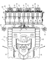
図3及び図4に示すように、苗植付装置23は、エンジン5からミッションケース6を経由した動力が伝達される植付入力ケース26と、植付入力ケース26に連結する8条用4組(2条で1組)の植付伝動ケース27と、各植付伝動ケース27の後端側に設けられた苗植機構28と、8条植え用の苗載台29と、各植付伝動ケース27の下面側に配置された田面均平用のフロート32とを備えている。苗植機構28には、1条分2本の植付爪30を有するロータリケース31が設けられている。植付伝動ケース27に2条分のロータリケース31が配置されている。ロータリケース31の1回転によって、2本の植付爪30が各々1株ずつの苗を切り取ってつかみ、フロート32にて整地された田面に植え付けることになる。
図示は省略するが、エンジン5からミッションケース6を経由した動力は、前車輪3及び後車輪4に伝達されるだけでなく、苗植付装置23の植付入力ケース26にも伝達される。この場合、ミッションケース6から苗植付装置23に向かう動力は、リヤアクスルケース9の右側上部に設けられた株間変速ケース(図示省略)に一旦伝達され、株間変速ケースから植付入力ケース26に動力伝達される。当該伝達された動力にて、各苗植機構28や苗載台29が駆動する。詳細は省略するが、株間変速ケースには、植え付けられる苗の株間を例えば疎植、標準植又は密植等に切り換える株間変速機構と、苗植付装置23への動力伝達を継断するPTOクラッチとが内蔵されている。
なお、苗植付装置23の左右外側にはサイドマーカ33を備えている。サイドマーカ33は、筋引き用のマーカ輪体34と、マーカ輪体34を回転可能に軸支するマーカアーム35とを有している。各マーカアーム35の基端側が苗植付装置23の左右外側に左右回動可能に軸支されている。サイドマーカ33は、運転操作部13にある作業レバー16の操作に基づき、次工程での基準となる軌跡を田面に着地して形成する作業姿勢と、マーカ輪体34を上昇させて田面から離間させた非作業姿勢とに回動可能に構成されている。
(2).エンジンの支持構造並びにエンジン周辺構造
次に、図3~図12を参照しながら、走行機体2に対するエンジン5の支持構造並びにエンジン5周辺構造について説明する。図3及び図4に示すように、走行機体2は前後に延びる左右一対の機体フレーム50を備えている。各機体フレーム50は前部フレーム51と後部フレーム52とに二分割されている。前部フレーム51の後端部と後部フレーム52の前端部とが左右横長の中間連結フレーム53に溶接固定されている。左右一対の前部フレーム51の前端部は前フレーム54に溶接固定されている。左右一対の後部フレーム52の後端側は後フレーム55に溶接固定されている。前フレーム54、左右両前部フレーム51及び中間連結フレーム53は平面視四角枠状に構成されている。同様に、中間連結フレーム53、左右両後部フレーム52及び後フレーム55も平面視四角枠状に構成されている。
次に、図3~図12を参照しながら、走行機体2に対するエンジン5の支持構造並びにエンジン5周辺構造について説明する。図3及び図4に示すように、走行機体2は前後に延びる左右一対の機体フレーム50を備えている。各機体フレーム50は前部フレーム51と後部フレーム52とに二分割されている。前部フレーム51の後端部と後部フレーム52の前端部とが左右横長の中間連結フレーム53に溶接固定されている。左右一対の前部フレーム51の前端部は前フレーム54に溶接固定されている。左右一対の後部フレーム52の後端側は後フレーム55に溶接固定されている。前フレーム54、左右両前部フレーム51及び中間連結フレーム53は平面視四角枠状に構成されている。同様に、中間連結フレーム53、左右両後部フレーム52及び後フレーム55も平面視四角枠状に構成されている。
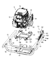
図5~図7に示すように、左右両前部フレーム51の前寄り部位は、前後二本のベースフレーム56によって連結されている。当該各ベースフレーム56は、その中間部が左右両前部フレーム51よりも低く位置するようにU字形に折り曲げられた形状に形成されている。各ベースフレーム56の左右端部がそれぞれ対応する前部フレーム51に溶接固定されている。略平板状のエンジン台57及び防振部材としての複数の防振ゴム58を介して、前後両ベースフレーム56にエンジン5が搭載され防振支持されている。前側のベースフレーム56は、これに溶接固定された前中継フレーム59を介して前フレーム54に連結されている。後側のベースフレーム56は、後中継ブラケット60を介してミッションケース6の前部に連結されている。なお、実施形態のエンジン5は、4ストロークV型2気筒のガソリンエンジンである。
図4から分かるように、左右両前部フレーム51の後寄り部位は、ミッションケース6の左右両側に突出したフロントアクスルケース7に連結されている。中間連結フレーム53の中央側には、側面視で後斜め下向きに延びるU字状フレーム61の左右両端部が溶接固定されている。U字状フレーム61の中間部がミッションケース6とリヤアクスルケース9とをつなぐ筒状フレーム8の中途部に連結されている(図3及び図4参照)。後フレーム55の中間部には、左右二本の縦フレーム62の上端側が溶接固定されている。左右両縦フレーム62の下端側には左右横長のリヤアクスル支持フレーム63の中間部が溶接固定されている。リヤアクスル支持ケース63の左右両端部がリヤアクスルケース9に連結されている。なお、左側の前部フレーム51に外向き突設されたステップ支持台64の下方に、エンジン5の排気音を低減させるマフラー65が配置されている。
図4~図6に示すように、エンジン5の後方に配置されたミッションケース6の前部には、パワーステアリングユニット66が設けられている。パワーステアリングユニット66の上面に立設されたハンドルポスト67の内部にハンドル軸(図示省略)が回動可能に配置されている。ハンドル軸の上端側に操縦ハンドル14が固定されている。パワーステアリングユニット66の下面側には操舵出力軸(図示省略)が下向きに突出している。当該操舵出力軸には、左右の前車輪6を操舵する操舵杆68(図4参照)がそれぞれ連結されている。
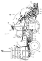
実施形態のエンジン5は、出力軸70(クランク軸)を左右方向に向けて前後両ベースフレーム56の中間部上に配置されている。エンジン5及びエンジン台57の左右幅は左右両前部フレーム51間の内法寸法よりも小さく、エンジン5の下部側及びエンジン台57は、前後両ベースフレーム56の中間部上に配置された状態で、左右両前部フレーム51よりも下側に露出している。この場合、エンジン5の出力軸70(軸線)は、側面視で左右両前部フレーム51と重なる位置にある。
エンジン5の出力軸70はエンジン5の左右両側面から外向きに突出している。出力軸70の一方の突端部(実施形態では右突端部)にはエンジン空冷用の吸引ファン71が設けられている(図5参照)。吸引ファン71は出力軸70と一体回転するように構成されている。吸引ファン71はファンカバー72にて覆われている。ファンカバー72の中央部に形成された冷却風取込口73には防塵網74が設けられている。吸引ファン71の回転にて冷却風取込口73から取り込まれた冷却風によって、エンジン5自体が強制的に冷却される。
実施形態の田植機1では、吸引ファン71の回転によって、フロントボンネット11(エンジンルームとも言える)内の左右一方から他方(実施形態では右側から左側)に向けて、エンジン5を冷やす冷却風(外気)が流通するように構成されている。すなわち、フロントボンネット11の左右両側面の下部側に、フロントボンネット11内外に冷却風を流通させる流通口75が形成されている。実施形態では、フロントボンネット11の左右両側面に、複数本のスリット状の貫通穴が上下に適宜間隔を空けて並ぶように形成されている。これら貫通穴群が流通口75に構成されている。
従って、吸引ファン71が回転すると、フロントボンネット11内の空気が右側から左側に流れてフロントボンネット11内の圧力が低下し、フロントボンネット11内外の圧力に差が生ずる。そうすると、右側の流通口75や、右側の前部フレーム51及び作業ステップ10の下方から冷却風が取り込まれ、当該取り込まれた冷却風によってエンジン5等が空冷される。フロントボンネット11内を流通して暖められた冷却風(排風)は、左側の流通口75や、左側の前部フレーム51及び作業ステップ10の下方から、フロントボンネット11外に排出される(図7参照)。
エンジン5の上面には、エアクリーナ(図示省略)を収容するクリーナケース76が上下に適宜間隔を空けて配置されている。クリーナケース76とエンジン5との間に形成された隙間は左右に突き抜けていて、吸引ファン71の回転にて取り込まれた冷却風が通過可能な上部通風路77(図7参照)に構成されている。図示は省略するが、クリーナケース76の下面側のうち吸引ファン71寄りの箇所には、クリーナケース76の内外を連通させる連通穴が形成されている。吸引ファン71の回転にて上部通風路77を通過する冷却風が連通穴を経由してクリーナケース76内に導入される。また、クリーナケース76はエンジン5の吸気系に接続されている。クリーナケース76内のエアクリーナにてろ過された冷却風がエンジン5の吸気系(キャブレータ等)に送られる。吸引ファン71の回転にて冷たい冷却風をクリーナケース76内に取り込むことによって、クリーナケース76内の温度上昇が抑制され、エンジン5の吸気系(キャブレータ等)に冷気が供給される。その結果、エンジン5の駆動効率の向上を図れる。
エンジン5の後面側には、エンジンオイル冷却用の第1オイルクーラ78が設けられている。また、ファンカバー72の外側には、冷却風取込口73に対峙するエンジンオイル冷却用の第2オイルクーラ79が配置されている。第2オイルクーラ79は第1オイルクーラ78に連通接続されていて、第1オイルクーラ78の冷却能力を補填する役割を担っている。吸引ファン71の回転によってフロントボンネット11内に取り込まれる冷却風が第1及び第2オイルクーラ78,79に吹き付けられ、第1及び第2オイルクーラ78,79(内部のエンジンオイル)が強制冷却される。実施形態の第2オイルクーラ79は右前部フレーム51とエンジン5右側面(ファンカバー72側)との間に位置していて、側面視で右側の前部フレーム51と重なるように配置されている。換言すると、第2オイルクーラ79は、エンジン5を上方から覆うフロントボンネット11よりも下側で、吸引ファン71に対峙させて配置されている。
図5~図7に示すように、フロントボンネット11内では、エンジン5を取り囲む略箱枠状のボンネットフレーム80が、前フレーム54とハンドルポスト67とに連結されている。ボンネットフレーム80の一側部(実施形態では右側部)に溶接固定された枝フレーム81には、上下に跨るように取付ブラケット82が設けられている。当該取付ブラケット82の下部側に第2オイルクーラ79が連結され、ファンカバー72の冷却風取込口73に臨ませている。このため、第2オイルクーラ79は、吸引ファン71の回転で、主に右側の前部フレーム51及び作業ステップ10の下方から取り込まれた冷却風によって、エンジン5よりも先に冷却されることになる。従って、第2オイルクーラ79専用の冷却ファンを用いることなく、第2オイルクーラ79の冷却効率を向上でき、第2オイルクーラ79の小型化にも貢献する。
取付ブラケット82の上部側には、エンジン5に関係するコントローラ等の電装部品83が取り付けられている。電装部品83は右側の流通口75にフロントボンネット11の内側から臨ませている。吸引ファン71の回転によって右側の流通口75を通り抜けた冷却風は電装部品83に吹き付けられ、電装部品83が冷却されることになる。右側の流通口75からの冷却風によって、エンジン5の周囲に配置された電装部品83の温度上昇を抑制できる。エンジン5の熱による電装部品83への悪影響を回避できる。なお、電装部品83を挟んで右側の流通口75の反対側に、クリーナケース76とエンジン5との間の上部通風路77の入口側が位置している(図7参照)。
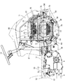
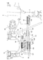
図6及び図7に示すように、エンジン5のうち吸引ファン71と反対側の他側面(実施形態では左側面)の上部側には、上部通風路77の出口側が開口している。そして、エンジン5左側面の上部側には、上部通風路77の出口側を取り囲むように、側面視門形の通風ダクト84が取り付けられている。通風ダクト84は、左側の前部フレーム51よりも高い位置におかれていて、左側の流通口75にフロントボンネット11の内側から臨ませている。通風ダクト84によってエンジン5の上部排風路85が形成されている。つまり、上部通風路77を通過してエンジン5の熱を奪って暖められた排風は、通風ダクト84を介して左側の流通口75からフロントボンネット11外に排出される。通風ダクト84の存在によって、暖められた排風がフロントボンネット11内に戻ってとどまるのを防止して左側の流通口75からスムーズに排出でき、排風の排出効率を向上できる。
図7に示すように、エンジン5の熱を奪って暖められた排風は、上部排風路85経由でフロントボンネット11外に排出されるだけでなく、左側の前部フレーム51及び作業ステップ10の下方を経由しても排出される。すなわち、左側の前部フレーム51及び作業ステップ10の下方は、エンジン5の下部排風路86に構成されている。
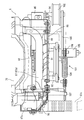
エンジン5のうち吸引ファン71と反対側の他側面(実施形態では左側面)には、エンジンの排気系に連通する排気管87が配置されている。排気管87は、通風ダクト84と出力軸70の他方の突端部(実施形態では左突端部)との間を横切ってから、出力軸70を挟んだ一方(実施形態では前側)で縦向きに延長したL字状に形成されている。実施形態の排気管87は、通風ダクト84と出力軸70との間を横切って延びる横管部87aと、出力軸70よりも前側で下向きに延長した縦管部87bと、縦管部87bの下端側からマフラー65に向けて延びる連結管部87cとにより構成されている。横管部87aの基端側がエンジン5の一方の気筒に接続されている。横管部87aのうち縦管部87b寄りの部位から分岐した部分はエンジン5の他方の気筒に接続されている。従って、両気筒からの排気ガスは、横管部87aにおける縦管部87bの手前で合流する。連結管部87cの先端側がマフラー65の排気入口側に接続されている。
エンジン5の左側面には、排気管87の横管部87a及び縦管部87bを囲う遮蔽カバー88が設けられている。実施形態の遮蔽カバー88は、横管部87aを覆う横カバー体89と、縦管部87bを覆う縦カバー体90とを備えている。横カバー体89は、上面板、後面板及び左側面板を有する金属板製のものである。また、縦カバー体90は、上面板、下面板、左右側面板及び前面板を有する金属板製のものである。すなわち、横カバー体89及び縦カバー体90は、出力軸70の他方の突端部(実施形態では左突端部)に設けられた排出ファン91側を開口させた略箱状に形成されている。横カバー体89と縦カバー体90とは、排気管87の横管部87aと縦管部87bとを囲う関係上、側面視で略L字状に並んでいる。遮蔽カバー88で排気管87の横管部87a及び縦管部87bを囲うことによって、排気管87から発生する熱がフロントボンネット11内で拡散するのを抑制している。なお、実施形態の通風ダクト84及び遮蔽カバー88は、左前部フレーム51とエンジン5左側面との間に位置していて、フロントボンネット11内に収まっていることは言うまでもない(図7参照)。
図6及び図9に示すように、エンジン5左側面のうち遮蔽カバー88の内側(横カバー体89と縦カバー体90とで仕切られた内側)には、出力軸70の他方の突端部(実施形態では左突端部)が突出している。出力軸70の左突端部には、吸引ファン71とは別個に、排出ファン91が設けられている。排出ファン91は、吸引ファン71と同様に、出力軸70と一体回転するように構成されている。排出ファン91の回転によって周囲の排風が取り込まれ、主に下部排風路86(左側の前部フレーム51及び作業ステップ10の下方)からフロントボンネット11外に排出される。従って、エンジン5右側面側の吸引ファン71の回転にてエンジン5に冷却風を吹き付けて、エンジン5を強制冷却するだけでなく、エンジン5左側面側の排出ファン91の回転にて、エンジン5の熱を奪って暖められた排風をフロントボンネット11外に排出することになり、吸引ファン71の冷却風取込効果と排出ファン91の排風排出効果とがあいまって、エンジン5の冷却効率を格段に向上できる。
また、前述の通り、横カバー体89及び縦カバー体90は排出ファン91側を開口させた略箱状に形成されているため、排気管87から発生する熱は、フロントボンネット11内で拡散せず、排出ファン91の回転によって下部排風路86経由でフロントボンネット11外に積極的に排出される。従って、排気管87のあるエンジン5左側面側の熱環境、ひいてはフロントボンネット11内の熱環境を改善できる。
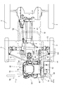
図6、図8、図9及び図11に示すように、出力軸70の左突端部には、排出ファン91だけでなく、回転力伝達用の出力プーリ92,93が複数個(実施形態では2つ)設けられている。出力プーリ92,93は、出力軸70の回転によって排出ファン91と共に回転するように構成されている。各出力プーリ92,93は、排出ファン91を挟んで出力軸70の軸線方向前後に振り分けて配置されている。エンジン5に近い方の出力プーリ92は、後述するジェネレータ94(詳細は後述する)への回転力伝達用の第1出力プーリ92であり、エンジンから遠い方の出力プーリ93は、ミッションケース6から左外側に突出したミッション入力軸97(詳細は後述する)への回転力伝達用の第2出力プーリ93である。
ここで、出力軸70の左突端部を挟んで排気管87の縦管部87bの反対側(実施形態では後側)に、ジェネレータ94が配置されている。ジェネレータ94は、エンジン5左側面のうち出力軸70の左突端部よりも左後方で且つ横カバー体89の下方にボルト締結された固定ブラケット95に取り付けられている。図示は省略するが、エンジン5左側面とジェネレータ94との間には左右に適宜間隔を空けている。ジェネレータ94のうちエンジン5左側面と対峙する側に、補機入力プーリ94aが設けられている。出力軸70側の第1出力プーリ92とジェネレータ94側の補機入力プーリ94aとに伝達ベルト96が巻き掛けられている。プーリ92及びベルト96伝動系を介して、エンジン5からジェネレータ94に回転力が伝達され、ジェネレータ94が発電する。ジェネレータ94は固定ブラケット95を介してエンジン5の左側面に取り付けられているから、エンジン5と同じ振動系に含まれることになる。このため、ジェネレータ94自体にかかる負荷を低減でき、ジェネレータ94の変形や破損のおそれを抑制できる。
一方、ミッションケース6から左外側に突出したミッション入力軸97には、ミッション入力プーリ98が設けられている。出力軸70側の第2出力プーリ93とミッションケース6側のミッション入力プーリ98とに伝達ベルト99が巻き掛けられている。プーリ93,98及びベルト99伝動系を介して、エンジン5からミッションケース6に回転力が伝達される。ミッション出力軸97のうちミッション入力プーリ98よりも左外側に、ミッションケース6空冷用のミッション冷却ファン100が設けられている。ミッション冷却ファン100は、プーリ93,98及びベルト99伝動系を介して伝達される回転力によってミッション入力プーリ98と共に回転するように構成されている。
図6及び図9に示すように、エンジン5左側面のうち遮蔽カバー88の内側に、排出ファン91、第1及び第2出力プーリ92,93、ジェネレータ94及び伝達ベルト96,99が配置される。このため、エンジン5左側面のうち遮蔽カバー88の内側に、プーリ92,93及びベルト96,99伝動系やジェネレータ94をコンパクトに配置したものでありながら、排出ファン91の回転によって、エンジン5左側面周辺の熱を下部排風路86経由でスムーズに排出できる。また、プーリ92,93及びベルト96,99伝動系やジェネレータ94に排風を吹き付けて冷やせるので、プーリ92,93及びベルト96,99伝動系やジェネレータ94の熱劣化を抑制でき、これらの耐久性向上を図れる。
図11から分かるように、排出ファン91の外径は各出力プーリ92,93よりも大径に構成されている。このため、排出ファン91の回転にて排風を下部排風路86経由で排出する際に、各出力プーリ92,93の存在が邪魔になるおそれが少なく、排出ファン91の回転による排風の排出効率を良好に維持できる。また、各出力プーリ92,93はエンジン5に近いものほど小径に構成されている。このため、排出ファン91の回転にてエンジン5左側面側の熱を奪う際に、エンジン5に近い方の第1出力プーリ92が存在する影響を少なくできる。その上、プーリ92,93及びベルト96,99伝動系の熱劣化を抑制しながら、出力軸70の左突端部に各出力プーリ92,93と排出ファン91とをコンパクトに配置でき、エンジン5ひいてはこれを覆うフロントボンネット11の左右幅の拡大を抑制できる。
図3、図6及び図11に示すように、出力軸70側の第2出力プーリ93とミッション出力プーリ98との間には、伝達ベルト99を緊張させる張力付与部材101が配置されている。張力付与部材101は、伝達ベルト99に下方から当接するテンションプーリ102を備えている。テンションプーリ102は、エンジン台57の左側部に上下回動可能に連結されたテンションアーム103の自由端側に軸支されている。テンションアーム103は、付勢ばね104によって上向き回動方向に引っ張られていて、テンションプーリ102を常時伝達ベルト99に下方から押圧当接させている。付勢ばね104は、テンションアーム103基端側のボス部105に立設された揺動アーム106と、エンジン台57の左側部に突設された支持板107との間に装架されている。
このように、エンジン5が搭載されるエンジン台57に張力付与部材101を設けると、張力付与部材101がエンジン5と同じ振動系に含まれることになるから、張力付与部材101自体にかかる負荷を低減できる。その結果、張力付与部材101の変形や破損のおそれを抑制できる。また、張力付与部材101の振動がエンジン5の振動に追従することになり、伝達ベルト99を適正なテンションがかかった状態に維持し易いという利点もある。実施形態では、エンジン5とミッションケース6とを前後に並べた状態で、第2出力プーリ93とミッション出力プーリ98との間に、張力付与部材101だけでなくジェネレータ94も一緒に位置させていて、エンジン5とミッションケース6との間のスペースの有効利用も図っている。
さて、実施形態のエンジン5は、前後両ベースフレーム56に複数の防振ゴム58を介して支持されたエンジン台57にボルト締結されている。図8、図9及び図12に示すように、エンジン台57には、エンジン5の底面に臨む上下貫通状の抜き穴108が形成されている。エンジン5の底面に形成されたリブ溝109をエンジン台57の抜き穴108に臨ませている。この場合、抜き穴108からエンジン左側面側の排出ファン91に向けて冷却風が流通するように、エンジン台57上にエンジン5が抜き穴108から(右側に)ずらして配置されている。換言すると、エンジン5の底面でエンジン台57の抜き穴108全体を覆い隠さずに抜き穴108の一部を上下に開口させている。エンジン台57の下側から抜き穴108を覗いた場合、抜き穴108の一部には、エンジン5の左側面側にある第1出力プーリ92や伝達ベルト96が見えることになる。
このように、エンジン5の底面に臨む上下貫通状の抜き穴108をエンジン台57に形成すると、吸引ファン71の回転にて取り込まれた冷却風をエンジン5の底面に吹き付けできるから、エンジン5内部のエンジンオイルを積極的に冷却して、エンジンオイル温度の過度の上昇を抑制できる。第1及び第2オイルクーラ78,79の冷却効率とあいまって、エンジンオイルの冷却を効果的に行い、エンジン5のヒートバランスを良好に保持できる。また、抜き穴108から排出ファン91に向けて冷却風が流通するように、エンジン台57上にエンジン5が抜き穴108からずらして配置されているから、排出ファン91の回転によって、エンジン5の底面側から左側面側に向けて抜き穴108経由で冷却風を送り込める。このため、エンジン5左側面周囲の排風に、比較的低温の冷却風を混合させて、排風自体の温度を低くでき、エンジン5左側面側の熱環境を大幅に改善できる。
(3).まとめ
上記の実施形態によると、走行機体2に搭載されたエンジン5と、前記エンジン5の動力を変速して前記走行機体2の走行部3,4に伝達するミッションケース6と、前記走行機体2に装着された苗植付装置23とを備えており、前記エンジン5の一側面にエンジン空冷用の吸引ファン71が設けられている田植機1であって、前記エンジン5のうち前記吸引ファン71と反対側の他側面には、前記他側面から突出した出力軸70を挟んで一方に、前記エンジン5の排気系に連通する排気管87(87b)を延長させ、他方にはジェネレータ94が配置されているから、前記出力軸70を挟んだ両側に前記排気管87(87b)と前記ジェネレータ94とを振り分けて、前記排気管87(87b)の熱による前記ジェネレータ94への悪影響を抑制しながら、前記エンジン5の他側面側に前記排気管87(87b)と前記ジェネレータ94とをコンパクトにまとめて配置できる。
上記の実施形態によると、走行機体2に搭載されたエンジン5と、前記エンジン5の動力を変速して前記走行機体2の走行部3,4に伝達するミッションケース6と、前記走行機体2に装着された苗植付装置23とを備えており、前記エンジン5の一側面にエンジン空冷用の吸引ファン71が設けられている田植機1であって、前記エンジン5のうち前記吸引ファン71と反対側の他側面には、前記他側面から突出した出力軸70を挟んで一方に、前記エンジン5の排気系に連通する排気管87(87b)を延長させ、他方にはジェネレータ94が配置されているから、前記出力軸70を挟んだ両側に前記排気管87(87b)と前記ジェネレータ94とを振り分けて、前記排気管87(87b)の熱による前記ジェネレータ94への悪影響を抑制しながら、前記エンジン5の他側面側に前記排気管87(87b)と前記ジェネレータ94とをコンパクトにまとめて配置できる。
また、前記出力軸70に固定された出力プーリ93と、前記ミッションケース6のミッション入力軸97に固定されたミッション入力プーリ98とに巻き掛けられた伝達ベルト99と、前記伝達ベルト99を緊張させる張力付与部材101とを更に備えており、前記出力プーリ93と前記ミッション入力プーリ98との間に、前記張力付与部材101及び前記ジェネレータ94を位置させているから、前記エンジン5と前記ミッションケース6との間のスペースを有効利用して、前記ミッションケース6へのプーリ93,98及びベルト99伝動系の配置のコンパクト化を図れる。
更に、前記走行機体2に防振部材58を介して取り付けられたエンジン台57に前記エンジン5が搭載されており、前記張力付与部材101が前記エンジン台57に取り付けられており、前記ジェネレータ94が前記エンジン5の前記他側面に締結された固定ブラケット95に取り付けられているから、前記張力付与部材101及び前記ジェネレータ94が前記エンジン5と同じ振動系に含まれることになる。このため、前記張力付与部材101及び前記ジェネレータ94自体にかかる負荷を低減でき、前記張力付与部材101及び前記ジェネレータ94の変形や破損のおそれを抑制できる。
上記の実施形態によると、走行機体2に搭載されたエンジン5と、前記エンジン5の動力を変速して前記走行機体2の走行部3,4に伝達するミッションケース6と、前記走行機体2に装着された苗植付装置23とを備えており、前記エンジン5の一側面にエンジン空冷用の吸引ファン71が設けられている田植機1であって、前記走行機体2を構成する左右一対の機体フレーム50の間に、前記エンジン5が前記両機体フレーム50よりも下側に突出するように配置されており、前記エンジン5のうち前記吸引ファン71と反対側の他側面には、前記機体フレーム50よりも上方に、前記吸引ファン71からの冷却風を通過させる通風ダクト84が配置されており、前記通風ダクト84によって前記エンジン5の上部排風路85が形成され、前記エンジン5の前記他側面側にある機体フレーム50の下方が前記エンジン5の下部排風路86に構成されているから、前記通風ダクト84の存在によって、前記エンジン5の熱を奪って暖められた排風がエンジンルーム内で拡散するのを抑制できる。その上、前記排風がエンジンルーム内に戻ってとどまるのを防止して、前記上部排風路85からスムーズに排出でき、排風の排出効率を向上できる。また、前記エンジン5の排風路を前記上部排風路85と前記下部排風路86との二つに分けて、前記排風を効率よく前記エンジンルーム外に排出でき、前記エンジン5の冷却効率を良好な状態に維持できる。
また、前記エンジン5の上面に、エアクリーナを収容するクリーナケース76が上下に適宜間隔を空けて配置されており、前記クリーナケース76と前記エンジン5との間の上部通風路77が前記通風ダクト84に連通しているから、前記吸引ファン71の回転にて前記エンジン5上面周辺に冷却風を取り込み、前記エンジン5上面周辺を冷却できる。そして、前記エンジン5上面周辺の熱を奪って暖められた排風を前記通風ダクト84経由でスムーズに排出できる。従って、前記エンジン5の冷却効率向上の一助になる。
更に、前記エンジン5の前記他側面から突出した出力軸70は、前記エンジン5の前記他側面側にある機体フレーム50と側面視で重なる位置にあり、前記エンジン5の排気系に連通する排気管87は、前記通風ダクト84と前記出力軸70との間を横切ってから、前記出力軸70を挟んで一方で縦向きに延長したL字状に形成されており、前記エンジン5の前記他側面には、前記排気管87を囲う遮蔽カバー88が設けられているから、前記遮蔽カバー88の存在によって、前記排気管87から発生する熱がエンジンルーム内で拡散するのを抑制できる。
上記の実施形態によると、走行機体2に搭載されたエンジン5と、前記エンジン5の動力を変速して前記走行機体2の走行部3,4に伝達するミッションケース6と、前記走行機体2に装着された苗植付装置23とを備えており、前記エンジン5の一側面にエンジン空冷用の吸引ファン71が設けられている田植機1であって、前記エンジン5のうち前記吸引ファン71と反対側の他側面には、前記吸引ファン71とは別個に、排出ファン91が設けられているから、前記エンジン5一側面側の前記吸引ファン71によって前記エンジン5に冷却風を吹き付けて、前記エンジン5を強制冷却するだけでなく、前記エンジン5他側面側の前記排出ファン91の回転にて、前記エンジン5の熱を奪って暖められた排風をエンジンルーム外に排出することになる。従って、前記吸引ファン71の冷却風取込効果と前記排出ファン91の排風排出効果とがあいまって、前記エンジン5の冷却効率を格段に向上できる。
また、前記エンジン5の出力軸70には前記排出ファン91と共に回転力伝達用の出力プーリ92,93が設けられており、前記排出ファン91と前記出力プーリ92,93とは、前記出力軸70の回転によって共に回転するように構成されているから、前記排出ファン91の回転を利用して前記出力プーリ92,93に風を吹き付け、前記出力プーリ92,93を冷却できる。このため、前記排出ファン91及び前記出力プーリ92,93をコンパクトに配置しつつ、前記出力プーリ92,93の熱劣化を抑制でき、これらの耐久性向上を図れる。前記排出ファン91及び前記出力プーリ92,93の配置のコンパクト化を図れるから、前記エンジン5ひいてはエンジンルームの左右幅の拡大を抑制できる。
更に、前記排出ファン91の外径は前記出力プーリ92,93よりも大径に構成されているから、前記排出ファン91の回転にて排風を排出する際に、前記出力プーリ92,93の存在が邪魔になるおそれが少なく、前記排出ファン91の回転による排風の排出効率を良好に維持できる。
しかも、前記出力プーリ92,93を複数個備えており、前記複数の出力プーリ92,93は前記エンジン5に近付くほど小径に構成されているから、前記排出ファン91の回転にて前記エンジン5他側面側の熱を奪う際に、前記エンジン5に近い方の出力プーリ92が存在する影響を少なくできる。
上記の実施形態によると、走行機体2に搭載されたエンジン5と、前記エンジン5の動力を変速して前記走行機体2の走行部3,4に伝達するミッションケース6と、前記走行機体2に装着された苗植付装置23とを備えており、前記エンジン5の一側面にエンジン空冷用の吸引ファン71が設けられている田植機1であって、前記走行機体2に防振部材58を介して取り付けられたエンジン台57に前記エンジン5が搭載されており、前記エンジン台57には、前記エンジン5の底面に臨む抜き穴108が形成されているから、前記吸引ファン71の回転にて取り込まれた冷却風を前記エンジン5の底面に吹き付けできる。従って、前記エンジン5内部のエンジンオイルを積極的に冷却して、エンジンオイル温度の過度の上昇を抑制でき、前記エンジン5のヒートバランスを良好に保持できる。
また、前記エンジン5のうち前記吸引ファン71と反対側の他側面には、前記吸引ファンとは別個に、排出ファンが設けられており、前記抜き穴から前記排出ファンに向けて冷却風が流通するように、前記エンジン台上に前記エンジンが前記抜き穴からずらして配置されているから、前記排出ファン91の回転によって、前記エンジン5の底面側から他側面側に向けて前記抜き穴108経由で冷却風を送り込めることになる。このため、前記エンジン5他側面周囲の排風に、比較的低温の冷却風を混合させて、排風自体の温度を低くでき、前記エンジン5他側面側の熱環境を大幅に改善できる。
更に、前記走行機体2を構成する左右一対の機体フレーム50の間に、前記エンジン5及び前記エンジン台57が前記両機体フレーム50よりも下側に突出するように配置されているから、前記エンジン5の底面側から冷却風をスムーズに取り込める。
上記の実施形態によると、走行機体2に搭載されたエンジン5と、前記エンジン5の動力を変速して前記走行機体2の走行部3,4に伝達するミッションケース6と、前記走行機体2に装着された苗植付装置23とを備えており、前記エンジン5の一側面にエンジン空冷用の吸引ファン71が設けられている田植機1であって、前記走行機体2を構成する左右一対の機体フレーム50の間に、前記エンジン5が前記両機体フレーム50よりも下側に突出するように配置されており、前記エンジン5を上方から覆うフロントボンネット11よりも下側で、前記吸引ファン71に対峙させてオイルクーラ79が配置されているから、前記オイルクーラ79は、前記吸引ファン71の回転で、主に前記機体フレーム50の下方から取り込まれた冷却風によって、前記エンジン5よりも先に冷却されることになる。従って、前記オイルクーラ79専用の冷却ファンを用いることなく、前記オイルクーラ79の冷却効率を向上できる。前記オイルクーラ79の小型化にも貢献する。
また、前記フロントボンネット11の下部側に形成された流通口75に、前記オイルクーラ79の上方に配置された電装部品83を臨ませ、前記エンジン5を取り囲むように前記フロントボンネット11内に設けられたボンネットフレーム80に、前記オイルクーラ79及び前記電装部品83を支持させているから、前記吸引ファン71の回転によって前記流通口75を通り抜けた冷却風が前記電装部品83に吹き付けられ、前記電装部品83が冷却されることになる。前記流通口75からの冷却風によって、前記エンジン5の周囲に配置された前記電装部品83の温度上昇を抑制できる。前記エンジン5の熱による前記電装部品83への悪影響を回避できる。前記ボンネットフレーム80を利用して前記オイルクーラ79と前記電装部品83との支持構造を簡素化できる。
上記の実施形態によると、走行機体2に搭載されたエンジン5と、前記エンジン5の動力を変速して前記走行機体2の走行部3,4に伝達するミッションケース6と、前記走行機体2に装着された苗植付装置23とを備えており、前記エンジン5の一側面にエンジン空冷用の吸引ファン71が設けられている田植機1であって、前記エンジン5は出力軸70を左右方向に向けて前記走行機体2に搭載されており、前記エンジン5のうち前記吸引ファン71と反対側の他側面に、前記吸引ファン71とは別個に、排出ファン91が設けられており、前記排出ファン91を囲う遮蔽カバー88が前記エンジン5の他側面に設けられているから、前記吸引ファン71の冷却風取込効果と前記排出ファン91の排風排出効果とがあいまって、前記エンジン5の冷却効率を格段に向上できることに加えて、前記遮蔽カバー88の存在によって、前記エンジン5左側面周辺の熱がエンジンルーム内で拡散するのを抑制できる。
また、前記エンジン5の出力軸70には前記排出ファン91と共に回転力伝達用の出力プーリ92,93が設けられており、前記エンジン5の他側面のうち前記遮蔽カバー88の内側に、前記排出ファン91、ジェネレータ94及びプーリ92,93及びベルト96,99伝動系が配置されているから、前記プーリ92,93及びベルト96,99伝動系や前記ジェネレータ94をコンパクトに配置しながら、前記排出ファン91の回転によって、前記エンジン5左側面周辺の熱をスムーズに排出できる。また、前記排出ファン91の回転によって、前記プーリ92,93及びベルト96,99伝動系や前記ジェネレータ94に排風を吹き付けて冷やせるから、前記プーリ92,93及びベルト96,99伝動系や前記ジェネレータ94の熱劣化を抑制でき、これらの耐久性向上を図れる。
(4).その他
本願発明は、前述の実施形態に限らず、様々な態様に具体化できる。各部の構成は図示の実施形態に限定されるものではなく、本願発明の趣旨を逸脱しない範囲で種々変更が可能である。
本願発明は、前述の実施形態に限らず、様々な態様に具体化できる。各部の構成は図示の実施形態に限定されるものではなく、本願発明の趣旨を逸脱しない範囲で種々変更が可能である。
1 田植機
2 走行機体
5 エンジン
6 ミッションケース
23 苗植付装置
50 機体フレーム
57 エンジン台
58 防振ゴム
70 出力軸
71 吸引ファン
75 流通口
76 クリーナケース
77 上部通風路
79 第2オイルクーラ
80 ボンネットフレーム
83 電装部品
84 通風ダクト
85 上部排風路
86 下部排風路
87 排気管
88 遮蔽カバー
91 排出ファン
94 ジェネレータ
95 固定ブラケット
96,99 伝達ベルト
98 ミッション入力プーリ
101 張力付与部材
108 抜き穴
2 走行機体
5 エンジン
6 ミッションケース
23 苗植付装置
50 機体フレーム
57 エンジン台
58 防振ゴム
70 出力軸
71 吸引ファン
75 流通口
76 クリーナケース
77 上部通風路
79 第2オイルクーラ
80 ボンネットフレーム
83 電装部品
84 通風ダクト
85 上部排風路
86 下部排風路
87 排気管
88 遮蔽カバー
91 排出ファン
94 ジェネレータ
95 固定ブラケット
96,99 伝達ベルト
98 ミッション入力プーリ
101 張力付与部材
108 抜き穴
Claims (6)
- 走行機体に搭載されたエンジンと、前記エンジンの動力を変速して前記走行機体の走行部に伝達するミッションケースと、前記走行機体に装着された苗植付装置とを備えており、前記エンジンの一側面にエンジン空冷用の吸引ファンが設けられている田植機であって、
前記エンジンのうち前記吸引ファンと反対側の他側面には、前記吸引ファンとは別個に、排出ファンが設けられている、
田植機。 - 前記エンジンの出力軸には前記排出ファンと共に回転力伝達用の出力プーリが設けられており、前記排出ファンと前記出力プーリとは、前記出力軸の回転によって共に回転するように構成されている、
請求項1に記載の田植機。 - 前記排出ファンの外径は前記出力プーリよりも大径に構成されている、
請求項2に記載の田植機。 - 前記出力プーリを複数個備えており、前記複数の出力プーリは前記エンジンに近付くほど小径に構成されている、
請求項3に記載の田植機。 - 前記排出ファンを囲う遮蔽カバーが前記エンジンの他側面に設けられている、
請求項1に記載の田植機。 - 前記エンジンの出力軸には前記排出ファンと共に回転力伝達用の出力プーリが設けられており、前記エンジンの他側面のうち前記遮蔽カバーの内側に、前記排出ファン、ジェネレータ及びプーリ及びベルト伝動系が配置されている、
請求項5に記載の田植機。
Priority Applications (3)
| Application Number | Priority Date | Filing Date | Title |
|---|---|---|---|
| CN201380016711.1A CN104219945A (zh) | 2012-03-27 | 2013-03-19 | 插秧机 |
| KR1020147025553A KR20140138718A (ko) | 2012-03-27 | 2013-03-19 | 이앙기 |
| IN7527DEN2014 IN2014DN07527A (ja) | 2012-03-27 | 2013-03-19 |
Applications Claiming Priority (4)
| Application Number | Priority Date | Filing Date | Title |
|---|---|---|---|
| JP2012-070643 | 2012-03-27 | ||
| JP2012-070646 | 2012-03-27 | ||
| JP2012070646A JP5844192B2 (ja) | 2012-03-27 | 2012-03-27 | 田植機 |
| JP2012070643A JP5829963B2 (ja) | 2012-03-27 | 2012-03-27 | 田植機 |
Publications (1)
| Publication Number | Publication Date |
|---|---|
| WO2013146476A1 true WO2013146476A1 (ja) | 2013-10-03 |
Family
ID=49259733
Family Applications (1)
| Application Number | Title | Priority Date | Filing Date |
|---|---|---|---|
| PCT/JP2013/057838 WO2013146476A1 (ja) | 2012-03-27 | 2013-03-19 | 田植機 |
Country Status (4)
| Country | Link |
|---|---|
| KR (1) | KR20140138718A (ja) |
| CN (1) | CN104219945A (ja) |
| IN (1) | IN2014DN07527A (ja) |
| WO (1) | WO2013146476A1 (ja) |
Cited By (2)
| Publication number | Priority date | Publication date | Assignee | Title |
|---|---|---|---|---|
| CN105052323A (zh) * | 2015-07-15 | 2015-11-18 | 俞升洋 | 一种低震动的插秧装置 |
| EP3311649A3 (en) * | 2016-08-26 | 2018-10-31 | Deere & Company | Zero turning radius mower |
Families Citing this family (1)
| Publication number | Priority date | Publication date | Assignee | Title |
|---|---|---|---|---|
| KR102558144B1 (ko) * | 2020-12-31 | 2023-07-21 | 주식회사 티와이엠 | 이식용 작업기의 동력전달장치 |
Citations (3)
| Publication number | Priority date | Publication date | Assignee | Title |
|---|---|---|---|---|
| JP2000326738A (ja) * | 1999-05-18 | 2000-11-28 | Kubota Corp | 水田作業機の原動部 |
| JP2003088221A (ja) * | 2001-09-14 | 2003-03-25 | Iseki & Co Ltd | コンバイン |
| JP2004001746A (ja) * | 2003-06-13 | 2004-01-08 | Kubota Corp | 乗用型移植機の原動部構造 |
Family Cites Families (3)
| Publication number | Priority date | Publication date | Assignee | Title |
|---|---|---|---|---|
| KR0177896B1 (ko) * | 1996-05-13 | 1999-02-01 | 미츠이 고헤이 | 승용형 이식기 |
| KR100974278B1 (ko) * | 2008-03-18 | 2010-08-06 | 볼보 컨스트럭션 이키프먼트 홀딩 스웨덴 에이비 | 건설장비의 엔진실 |
| CN201512745U (zh) * | 2009-09-22 | 2010-06-23 | 西安宏大交通科技有限公司 | 一种路面铣刨机冷却系统 |
-
2013
- 2013-03-19 WO PCT/JP2013/057838 patent/WO2013146476A1/ja active Application Filing
- 2013-03-19 KR KR1020147025553A patent/KR20140138718A/ko not_active Application Discontinuation
- 2013-03-19 CN CN201380016711.1A patent/CN104219945A/zh active Pending
- 2013-03-19 IN IN7527DEN2014 patent/IN2014DN07527A/en unknown
Patent Citations (3)
| Publication number | Priority date | Publication date | Assignee | Title |
|---|---|---|---|---|
| JP2000326738A (ja) * | 1999-05-18 | 2000-11-28 | Kubota Corp | 水田作業機の原動部 |
| JP2003088221A (ja) * | 2001-09-14 | 2003-03-25 | Iseki & Co Ltd | コンバイン |
| JP2004001746A (ja) * | 2003-06-13 | 2004-01-08 | Kubota Corp | 乗用型移植機の原動部構造 |
Cited By (2)
| Publication number | Priority date | Publication date | Assignee | Title |
|---|---|---|---|---|
| CN105052323A (zh) * | 2015-07-15 | 2015-11-18 | 俞升洋 | 一种低震动的插秧装置 |
| EP3311649A3 (en) * | 2016-08-26 | 2018-10-31 | Deere & Company | Zero turning radius mower |
Also Published As
| Publication number | Publication date |
|---|---|
| IN2014DN07527A (ja) | 2015-04-24 |
| KR20140138718A (ko) | 2014-12-04 |
| CN104219945A (zh) | 2014-12-17 |
Similar Documents
| Publication | Publication Date | Title |
|---|---|---|
| JP3862674B2 (ja) | 乗用型移植機 | |
| JP5997469B2 (ja) | 田植機 | |
| JP2001199251A (ja) | 作業車の原動部冷却構造 | |
| WO2013146476A1 (ja) | 田植機 | |
| WO2013146475A1 (ja) | 田植機 | |
| JP5288290B2 (ja) | 作業車輌の原動部構造 | |
| JP5964100B2 (ja) | 田植機 | |
| JP5829963B2 (ja) | 田植機 | |
| JP5600020B2 (ja) | 作業車両 | |
| JP6015960B2 (ja) | コンバイン | |
| JP5844191B2 (ja) | 田植機 | |
| JP5844192B2 (ja) | 田植機 | |
| JP5844190B2 (ja) | 田植機 | |
| JP6032569B2 (ja) | 作業車輌の原動部構造 | |
| JP2010168043A (ja) | 田植機 | |
| TW201507598A (zh) | 作業車輛的原動部構造 | |
| JP5737522B2 (ja) | 作業車両の原動部構造 | |
| JP2009279978A (ja) | 作業車両 | |
| JPH09300986A (ja) | 乗用型移植機の原動部構造 | |
| JP2012143240A (ja) | 田植機 | |
| JP2014134104A (ja) | 作業車輌 | |
| JP5513363B2 (ja) | 作業機 | |
| JP7243667B2 (ja) | 作業車両 | |
| JP5527553B2 (ja) | コンバイン | |
| JP4462573B2 (ja) | バーチカルエンジン搭載作業車の冷却機構 |
Legal Events
| Date | Code | Title | Description |
|---|---|---|---|
| 121 | Ep: the epo has been informed by wipo that ep was designated in this application |
Ref document number: 13769585 Country of ref document: EP Kind code of ref document: A1 |
|
| ENP | Entry into the national phase |
Ref document number: 20147025553 Country of ref document: KR Kind code of ref document: A |
|
| NENP | Non-entry into the national phase |
Ref country code: DE |
|
| 122 | Ep: pct application non-entry in european phase |
Ref document number: 13769585 Country of ref document: EP Kind code of ref document: A1 |