WO2013140686A1 - 媒体収納繰出装置及び媒体取引装置 - Google Patents
媒体収納繰出装置及び媒体取引装置 Download PDFInfo
- Publication number
- WO2013140686A1 WO2013140686A1 PCT/JP2012/082568 JP2012082568W WO2013140686A1 WO 2013140686 A1 WO2013140686 A1 WO 2013140686A1 JP 2012082568 W JP2012082568 W JP 2012082568W WO 2013140686 A1 WO2013140686 A1 WO 2013140686A1
- Authority
- WO
- WIPO (PCT)
- Prior art keywords
- drum
- medium
- outer peripheral
- peripheral surface
- banknote
- Prior art date
- Legal status (The legal status is an assumption and is not a legal conclusion. Google has not performed a legal analysis and makes no representation as to the accuracy of the status listed.)
- Ceased
Links
Images




Classifications
-
- B—PERFORMING OPERATIONS; TRANSPORTING
- B65—CONVEYING; PACKING; STORING; HANDLING THIN OR FILAMENTARY MATERIAL
- B65H—HANDLING THIN OR FILAMENTARY MATERIAL, e.g. SHEETS, WEBS, CABLES
- B65H29/00—Delivering or advancing articles from machines; Advancing articles to or into piles
- B65H29/006—Winding articles into rolls
-
- B—PERFORMING OPERATIONS; TRANSPORTING
- B65—CONVEYING; PACKING; STORING; HANDLING THIN OR FILAMENTARY MATERIAL
- B65H—HANDLING THIN OR FILAMENTARY MATERIAL, e.g. SHEETS, WEBS, CABLES
- B65H2301/00—Handling processes for sheets or webs
- B65H2301/40—Type of handling process
- B65H2301/41—Winding, unwinding
- B65H2301/419—Winding, unwinding from or to storage, i.e. the storage integrating winding or unwinding means
- B65H2301/4191—Winding, unwinding from or to storage, i.e. the storage integrating winding or unwinding means for handling articles of limited length, e.g. AO format, arranged at intervals from each other
- B65H2301/41912—Winding, unwinding from or to storage, i.e. the storage integrating winding or unwinding means for handling articles of limited length, e.g. AO format, arranged at intervals from each other between two belt like members
-
- B—PERFORMING OPERATIONS; TRANSPORTING
- B65—CONVEYING; PACKING; STORING; HANDLING THIN OR FILAMENTARY MATERIAL
- B65H—HANDLING THIN OR FILAMENTARY MATERIAL, e.g. SHEETS, WEBS, CABLES
- B65H2404/00—Parts for transporting or guiding the handled material
- B65H2404/70—Other elements in edge contact with handled material, e.g. registering, orientating, guiding devices
- B65H2404/74—Guiding means
- B65H2404/741—Guiding means movable in operation
- B65H2404/7414—Guiding means movable in operation pivotable
-
- B—PERFORMING OPERATIONS; TRANSPORTING
- B65—CONVEYING; PACKING; STORING; HANDLING THIN OR FILAMENTARY MATERIAL
- B65H—HANDLING THIN OR FILAMENTARY MATERIAL, e.g. SHEETS, WEBS, CABLES
- B65H2404/00—Parts for transporting or guiding the handled material
- B65H2404/70—Other elements in edge contact with handled material, e.g. registering, orientating, guiding devices
- B65H2404/74—Guiding means
- B65H2404/743—Guiding means for guiding longitudinally
-
- B—PERFORMING OPERATIONS; TRANSPORTING
- B65—CONVEYING; PACKING; STORING; HANDLING THIN OR FILAMENTARY MATERIAL
- B65H—HANDLING THIN OR FILAMENTARY MATERIAL, e.g. SHEETS, WEBS, CABLES
- B65H2404/00—Parts for transporting or guiding the handled material
- B65H2404/70—Other elements in edge contact with handled material, e.g. registering, orientating, guiding devices
- B65H2404/74—Guiding means
- B65H2404/743—Guiding means for guiding longitudinally
- B65H2404/7431—Guiding means for guiding longitudinally along a curved path
-
- B—PERFORMING OPERATIONS; TRANSPORTING
- B65—CONVEYING; PACKING; STORING; HANDLING THIN OR FILAMENTARY MATERIAL
- B65H—HANDLING THIN OR FILAMENTARY MATERIAL, e.g. SHEETS, WEBS, CABLES
- B65H2701/00—Handled material; Storage means
- B65H2701/10—Handled articles or webs
- B65H2701/19—Specific article or web
- B65H2701/1912—Banknotes, bills and cheques or the like
Definitions
- the present invention relates to a medium storing and feeding apparatus and a medium transaction apparatus, and is suitable for application to, for example, an automatic teller machine (ATM) that performs a desired transaction by inserting a medium such as banknotes.
- ATM automatic teller machine
- a banknote deposit / withdrawal port for receiving and receiving banknotes with a customer
- a discrimination unit for discriminating the denomination and authenticity of inserted banknotes, and temporarily inserting inserted banknotes
- a temporary holding unit for holding and a denomination cassette for storing banknotes for each denomination
- This automatic teller machine discriminates the inserted banknotes in the discrimination section when the customer inserts banknotes into the banknote deposit / withdrawal port in the deposit transaction. And while an automatic teller machine holds the banknote discriminated from a normal banknote in a temporary storage part, it returns the banknote discriminated that it should not trade to a banknote depositing / withdrawing port and returning it to a customer. Subsequently, when the deposit amount is confirmed by the customer, the automatic teller machine re-discriminates the denomination of the banknote held in the temporary holding unit by the discrimination unit, and transfers it to each denomination cassette according to the denominated type. Store.
- the temporary storage unit for example, a rotating cylindrical drum and a pair of long tapes facing each other, and one end of each tape fixed so as to overlap the outer peripheral surface of the drum have been proposed (for example, JP, 2010-1123, A).
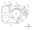
- the temporary storage unit 115 is configured such that each component is attached to the temporary storage unit housing 120.
- the temporary storage unit 115 is orthogonal to the conveyance direction of the bills BL by the upper tape 33 and the lower tape 36 while guiding the bills BL (see FIG. 13) sequentially conveyed from the discrimination unit or the like by the movable guide 141. The left and right center part is sandwiched from both sides. Then, the temporary storage unit 115 rotates the drum 31 and winds the banknote BL around the outer peripheral surface as it is, so that the banknote BL is placed in the space between the inner surface 120E of the temporary storage unit housing 120 and the outer peripheral surface of the drum 31. Temporary hold is made.
- the movable guide 141 rotates around the rotation shaft 45 in accordance with the change in the thickness of the bill BL wound around the drum 31. For this reason, a gap SP is opened between the left end portion of the movable guide 141 shown in FIG. 12 and the inner side surface 120 ⁇ / b> E of the temporary storage unit housing 120.
- the banknote BL may be cut from the end in the process of distribution in the market.
- interruption from the edge part may be discharged
- the banknote BL may be transported in a state where the cuts that are split along the transport direction are shifted from the upper tape 33 and the lower tape 36 in the width direction of the banknote BL. .
- the present invention has been made in consideration of the above points, and intends to propose a medium storing and feeding apparatus and a medium transaction apparatus that can remarkably improve the reliability of conveying a medium.
- a cylindrical and rotatably supported paper-like medium is wound around the outer peripheral surface, so that the opposed portion and the outer peripheral surface are opposed to the outer peripheral surface.
- This medium storing and feeding device can prevent the medium from entering the gap by conveying the medium along the movable portion and the facing portion.
- the customer service unit that receives transactions relating to the paper-like medium
- the transport unit that conveys the medium received by the customer service unit
- the cylindrical support member that is rotatably supported and winds the medium around the outer peripheral surface.
- This medium transaction apparatus can prevent the medium from entering the gap by conveying the medium along the movable portion and the facing portion.
- the present invention it is possible to prevent the medium from entering the gap by conveying the medium along the movable portion and the facing portion.
- the present invention can realize a medium storage and feeding apparatus and a medium transaction apparatus that can remarkably improve the reliability of medium conveyance.
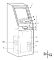
- an automatic teller machine 1 as an example of a medium transaction apparatus includes a box-shaped housing 2.
- the automatic teller machine 1 is installed in a financial institution or the like and performs transactions relating to cash such as deposit transactions and withdrawal transactions with customers.
- the case 2 has a portion where it is easy to insert a bill as an example of a medium or operate with a touch panel in a state where the customer faces the front side of the case 2, that is, a portion extending from the upper part of the front surface to the upper surface is inclined. It has a shape that is cut off.
- the housing 2 is provided with a customer service portion 3 in a portion extending from the upper part of the front surface to the upper surface.
- the customer service section 3 directly exchanges cash, bankbooks, etc. with the customer, and receives notification of information on transactions and reception of operation instructions.
- the customer service unit 3 is provided with, for example, a card slot 4, a deposit / withdrawal port 5, an operation display unit 6, a numeric keypad 7, and a receipt issuing port 8.
- Card entry / exit 4 is a portion where various cards such as cash cards are inserted or ejected.
- a card processing unit (not shown) for reading account numbers and the like magnetically recorded on various cards is provided on the back side of the card slot 4.
- the deposit / withdrawal port 5 is a portion where banknotes to be deposited by the customer are inserted and banknotes to be dispensed to the customer are discharged.
- the deposit / withdrawal port 5 is opened or closed by driving a shutter.
- a banknote is comprised by the rectangular paper as an example.
- the operation display unit 6 is integrated with an LCD (Liquid Crystal Display) for displaying an operation screen at the time of transaction and a touch panel for selecting a transaction type, inputting a personal identification number, transaction amount, and the like.
- LCD Liquid Crystal Display
- the numeric keypad 7 is a physical key that accepts input of numbers such as “0” to “9”.
- the numeric keypad 7 is used when inputting a password, transaction amount, or the like.
- the receipt issuing port 8 is a part for issuing a receipt on which transaction details are printed at the end of transaction processing.
- a receipt processing unit (not shown) that prints transaction contents or the like on a receipt is provided on the back side of the receipt issuing port 8.
- the side facing the customer is defined as the front side, and the opposite side of the front side is defined as the rear side.
- the left and right sides are respectively defined as the left side and the right side as viewed from the customer facing the front side, and further, the upper side and the lower side are defined.
- a main control unit 9 for overall control of the automatic teller machine 1, a banknote depositing / dispensing machine 10 as an example of a medium storing and feeding device for performing various processes relating to banknotes.
- the main control unit 9 includes a CPU (Central Processing Unit) (not shown).
- the main control unit 9 reads out and executes a predetermined program from a ROM (Read Only Memory), a flash memory or the like (not shown), thereby performing various processes such as a deposit transaction and a withdrawal transaction. .
- ROM Read Only Memory
- flash memory or the like
- the main control unit 9 includes a storage unit 9A including a RAM (Random Access Memory), a hard disk drive, a flash memory, and the like.
- the main control unit 9 stores various information in the storage unit 9A.
- the housing 2 has a door that can be opened and closed on a part of its side, such as the front side and the rear side. That is, the housing
- the housing 2 is configured such that, when maintenance work is performed by an operator or the like, the doors are opened as necessary to easily perform work on the respective internal parts.
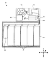
- the banknote depositing and dispensing machine 10 has a configuration in which a plurality of parts that perform various processes related to banknotes are combined. Each part of the bill depositing / dispensing machine 10 is controlled by the bill control unit 11.
- the banknote control unit 11 includes a CPU (not shown) as with the main control unit 9 (see FIG. 1). And the banknote control part 11 performs various processes, such as the process which determines the conveyance destination of a banknote, by reading and running a predetermined program from ROM, flash memory, etc. which are not shown in figure.
- the banknote control part 11 has 11 A (refer FIG. 1) of memory
- the banknote control unit 11 for example, when a customer performs a deposit transaction for depositing banknotes, receives a predetermined operation input via the operation display unit 6, then opens the shutter of the deposit / withdrawal port 5 and within the deposit / withdrawal unit 12. Insert the banknotes.
- the deposit / withdrawal unit 12 closes the shutter of the deposit / withdrawal port 5 and then takes out the banknotes one by one and delivers them to the transport unit 13.
- the conveyance part 13 advances the banknote comprised by the rectangular paper sheet shape along the short side direction of the said banknote, and conveys it to the discrimination part 14.
- the discrimination unit 14 discriminates the denomination and authenticity of the banknote, the degree of damage, and the like using an optical element, a magnetic detection element and the like while conveying the banknote inside. And the discrimination part 14 notifies the discrimination result of the said banknote to the banknote control part 11. In response to this, the banknote control unit 11 determines the transport destination of the banknote based on the acquired discrimination result.
- the conveyance unit 13 temporarily holds the banknote discriminated from the normal banknote in the discrimination unit 14 by conveying it to the temporary storage unit 15. Moreover, the conveyance part 13 conveys the reject banknote discriminated that it should not trade to the deposit or withdrawal part 12. Then, the reject banknote is returned to the customer.
- the banknote control unit 11 allows the customer to confirm the deposit amount via the operation display unit 6 and causes the transport unit 13 to transport the banknotes held in the temporary storage unit 15 to the discrimination unit 14. And the banknote control part 11 makes the discrimination part 14 discriminate
- the banknote control unit 11 causes the transport unit 13 to transport the banknote as a banknote that should not be reused and store it. If the degree of damage to the banknote is small, the banknote control unit 11 causes the transport unit 13 to transport the banknote as a banknote to be reused, and causes the discrimination unit 14 to distinguish the banknote again.
- the conveyance part 13 conveys and stores the banknote discriminated from the normal banknote in the discrimination part 14 to the banknote cassette 17 according to the denomination of the banknote. Moreover, the conveyance part 13 conveys the banknote discriminated that it should not trade to the collection
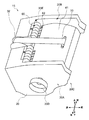
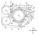
- the temporary storage unit 15 has a configuration in which components are attached to the temporary storage unit housing 20.
- the temporary storage unit housing 20 forms an internal space 20A surrounded by the partition wall by using most of the outer periphery such as the front side, the rear side, the left side and the right side, and the lower side as partition walls. Also, a bill insertion / removal hole 20 ⁇ / b> C as an example of an entry / exit hole serving as a bill entrance / exit into the internal space 20 ⁇ / b> A is formed below the front side surface of the temporary storage unit housing 20.
- the temporary storage unit housing 20 can be accessed from the outside to the internal space 20A through the open part 20B in which the upper partition is omitted from the outer periphery.
- gears and the like for transmitting a driving force from a motor (not shown) to a drum, a roller and the like to be described later are incorporated.
- an operation knob 20D for manually rotating a drum, a roller, or the like during maintenance work is provided on the left side surface of the temporary storage unit housing 20.
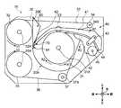
- the drum 31 has a cylindrical shape with a relatively large radius.
- the drum 31 is attached so as to be able to rotate in the winding direction R1 or the feeding direction R2 around the rotation shaft 31X along the left-right direction in the internal space 20A (see FIG. 3) of the temporary storage unit housing 20. It has been.
- FIG. 5 shows a state where the smallest number of banknotes in design is wound around the drum 31 and the apparent outer diameter of the drum 31 is minimized (hereinafter referred to as the thinnest state).
- FIG. 6 shows a state in which the largest number of banknotes in design is wound around the drum 31 and the apparent outer diameter of the drum 31 is maximized (hereinafter referred to as the thickest state).
- the upper reel 32 is configured in a bobbin shape. Further, the upper reel 32 is disposed on the upper side of the drum 31, that is, at a position closer to the rear on the open portion 20 ⁇ / b> B (see FIG. 3) side and substantially on the left and right. The upper reel 32 is provided to rotate about a rotation shaft 32X parallel to the rotation shaft 31X of the drum 31.
- An upper tape 33 as an example of a tape is wound around the upper reel 32.
- the upper tape 33 is made of a thin film-like resin, has a tape width sufficiently shorter than the long side of the banknote, and has a sufficient length in the longitudinal direction.
- An upper roller 34 formed in a cylindrical shape smaller than the upper reel 32 is provided on the front side of the drum 31 as viewed from the upper reel 32, that is, on the bill insertion / exit hole 20C (see FIG. 3) side.
- the upper roller 34 is formed such that its axial length is longer than the tape width of the upper tape 33.
- the upper roller 34 is configured to freely rotate about a rotation shaft 34X parallel to the rotation shaft 31X of the drum 31.
- the upper tape 33 pulled out from the upper reel 32 is passed forward through the open portion 20B (see FIG. 3), and then turned back through the upper roller 34 so as to be folded back downward. It is.
- the upper tape 33 is pressed against the drum 31 by a predetermined roller provided on the movable guide 41 described later, and the tip portion thereof is fixed to the drum 31.
- the upper reel 32 is biased by a tension spring (not shown) in a winding direction V1, which is a direction in which the upper tape 33 is wound.
- a tension spring (not shown) in a winding direction V1, which is a direction in which the upper tape 33 is wound.
- the lower reel 35 is configured in a spool form similar to the upper reel 32. Further, the lower reel 35 is disposed below the upper reel 32, that is, at a position closer to the rear on the lower side of the drum 31. The lower reel 35 is provided so as to be rotatable around a rotation shaft 35X parallel to the rotation shaft 31X of the drum 31.
- a lower tape 36 configured in the same manner as the upper tape 33 is wound around the lower reel 35.
- the lower reel 35 is biased by a tension spring (not shown) in a winding direction V3 that is a direction in which the lower tape 36 is wound.
- the temporary holding unit 15 always gives the lower tape 36 a predetermined tension.
- the winding direction V3 of the lower tape 36 in the lower reel 35 is opposite to the winding direction V1 of the upper tape 33 in the upper reel 32.
- a lower roller 37 that rotates around a rotation shaft 37X that is parallel to the rotation shaft 31X of the drum 31 is provided in front of the lower reel 35.
- the lower roller 37 has a cylindrical shape like the upper roller 34. Further, the lower roller 37 is provided at a position where the length in the left-right direction is longer than the tape width of the lower tape 36 and is substantially at the center on the left and right.
- the lower tape 36 drawn out from the lower reel 35 is passed in the forward direction, and then drawn upward through the lower roller 37 to move upward. Further, the lower tape 36 is pressed against the drum 31 after being directed rearward through a predetermined roller provided on a medium guide 42 described later. The tip of the lower tape 36 is fixed to the drum 31.
- the lower tape 36 has a tip fixed to the outer peripheral surface of the drum 31. Further, the upper tape 33 is fixed so that the tip thereof overlaps the outer peripheral side of the lower tape 36 on the outer peripheral surface of the drum 31.
- the temporary storage unit 15 winds the lower tape 36 and the upper tape 33 so as to overlap each other on the outer peripheral surface thereof.
- the temporary storage unit 15 sandwiches the banknote between the lower tape 36 and the upper tape 33 and winds the banknote around the outer peripheral surface of the drum 31 together with the lower tape 36 and the upper tape 33.
- maintains a banknote in the space between the outer peripheral surface of the drum 31 and the inner surface 20E of the temporary storage part housing
- the movable portion 40 has a configuration in which an upper movable guide 41 and a lower medium guide 42 are connected by a connecting portion 43.
- a conveyance path 44 is formed between the movable guide 41 and the medium guide 42 so as to have a gap sufficiently wider than the thickness of the bill.
- the medium guide 42 is formed in a drop shape or a wedge shape when viewed from the left and right side surfaces, and the rotating shaft 45 penetrates in the left and right direction below the front side.
- left and right inner surfaces of the temporary storage unit housing 20 are provided with a rotation hole (not shown) corresponding to the rotation shaft 45 above the front side.
- the medium guide 42 When the medium guide 42 is attached so that the rotation shaft 45 is inserted through the rotation hole of the temporary storage unit housing 20, the medium guide 42 opens or closes with respect to the temporary storage unit housing 20 around the rotation shaft 45. It can be rotated in the direction W2 (see FIG. 5).
- the movable guide 41 as a whole is formed in a curved plate shape so as to cover the drum 31 from the upper side in the open portion 20B formed on the upper side of the temporary storage unit housing 20 (see FIG. 3).
- the lower surface of the movable guide 41 is substantially flat in the central portion that covers the range from the front portion of the drum 31 to the rear portion of the medium guide 42.
- the movable guide 41 has a shape in which the lower surface of the movable guide 41 hangs downward as it moves backward so as to draw an arc having a larger radius of curvature than the outer peripheral surface of the drum 31 at the rear portion covering the rear side of the drum 31. It has become.
- the movable guide 41 hangs downward as the lower surface advances forward so as to conform to the shape of the upper surface of the medium guide 42, that is, to form the transport path 44, at the front portion facing the front portion of the medium guide 42. It has a shape.
- a winding roller 53 is provided at a position almost directly above the rotation shaft 31X penetrating the drum 31.
- the winding roller 53 is configured in a cylindrical shape and is disposed so as to expose the lower side from the lower surface of the movable guide 41, and is freely penetrated by a shaft along the left-right direction.
- the movable guide 41 can guide the banknote sandwiched between the upper tape 33 and the lower tape 36 to be pressed against the outer peripheral surface of the drum 31 while extending in the long side direction when the drum 31 rotates.
- the banknotes sandwiched between the upper tape 33 and the lower tape 36 are those in which only the central portion is sandwiched between the upper tape 33 and the lower tape 36 while there is a risk of bending in the long side direction.
- the apparent outer diameter of the drum 31 increases as a large number of banknotes are sequentially wound.
- the movable guide 41 is gradually lifted upward by the drum 31 as the apparent outer diameter of the drum 31 increases, and rotates in the opening direction W ⁇ b> 1 about the rotation shaft 45. .
- the movable unit 40 can always bring the winding roller 53 in the movable guide 41 into contact with the drum 31. And the movable part 40 can make the conveyance direction and conveyance destination of a banknote follow the outer peripheral surface of the drum 31.
- the movable unit 40 sandwiches the banknote between the upper tape 33 and the lower tape 36 in the vicinity of the upper end of the outer peripheral surface of the drum 31. Is brought into contact with the outer peripheral surface of the drum 31.
- the temporary storage unit 15 rotates the drum 31 in the winding direction R1. Thereby, the temporary storage part 15 can wind the banknote pinched
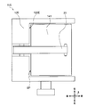
- a housing claw portion 60 as an example of a facing claw portion having a predetermined width in the left-right direction is provided on the upper portion of the rear end of the inner side surface 20E of the temporary storage portion housing 20. Yes. A plurality of housing claw portions 60 are provided to protrude forward with a certain interval in the left-right direction.
- the housing claw portion 60 has a substantially triangular shape in a side view (see FIG. 6), and the length in the front-rear direction becomes longer from the lower side to the upper side.
- a plurality of housing claw portions 60 are provided side by side in the left-right direction, so that a surface virtually opposed to the outer peripheral surface of the drum 31 and formed over the front ends of the plurality of housing claw portions 60, It is also called a facing part 64.
- the upper portion of the inner side surface 20E behind the temporary storage unit housing 20 is a portion where the housing claw portion 60 is not formed in plan view (see FIG. 4) (hereinafter also referred to as a housing claw recess 66). However, the shape is recessed backward from the facing portion 64.
- a plurality of guide claw portions 62 as an example of the movable portion claw portion are provided protruding rearward.
- the plurality of guide claws 62 have substantially the same width as the case claw 60 in the left-right direction in plan view (see FIG. 4).
- the plurality of guide claws 62 are provided at the rear end of the movable guide 41 with substantially the same spacing as the case claw 60 in the left-right direction.
- the rear end of the movable guide 41 has a shape in which a portion where the guide claw portion 62 is not formed in plan view (hereinafter also referred to as a guide claw recess 68) is recessed forward from the rear end of the movable guide 41. Yes.
- the width of the guide claw 62 in the left-right direction is narrower than the width of the housing claw recess 66. Further, the width of the housing claw portion 60 is formed narrower than the width of the guide claw recess 68.
- the guide claw portion 62 and the case claw portion 60 are engaged with each other while being fitted with play.
- the rear end of the movable guide 41 is positioned rearward of the facing portion 64, that is, separated from the drum 31 than the facing portion 64.
- a plurality of guide claw parts 62 are provided side by side in the left-right direction, so that a surface virtually formed opposite to the outer peripheral surface of the drum 31 at the front end of the plurality of guide claw parts 62 is defined as a guide tip. Also referred to as face 70.
- the movable guide 41 when changing from the thinnest state shown in FIG. 5 to the thickest state shown in FIG. 7, the movable guide 41 is centered on the rotation shaft 45 in accordance with the change in the thickness of the bill BL wound around the drum 31. Rotate. For this reason, the rear end (guide claw portion 62) of the movable guide 41 moves upward along the track T shown in FIG. 7 while moving slightly forward. In FIG. 7, the thinnest guide claw 62 is indicated by a broken line.
- the casing claw portion 60 has a length in the front-rear direction that increases from the bottom to the top in a side view.
- a virtual line extending from the center of the rotation shaft 31X toward the intersection point P where the guide tip surface 70 and the facing portion 64 intersect is represented by the radial line LR.
- the direction perpendicular to the radial line LR at the intersection P and substantially along the feeding direction R2 is the traveling direction DM of the leading edge of the banknote BL when the banknote BL is fed out of the drum 31.
- the angle formed by the guide tip surface 70 of the guide claw 62 at the intersection P and the traveling direction DM (hereinafter also referred to as the guide tip angle AT) is set to 0 degree or more and 30 degrees or less.
- the temporary storage unit 15 peels the banknote BL from the outer periphery of the drum 31 and feeds the banknote BL to the outside through the transport path 44.
- the banknote BL which is shifted in the width direction from the upper tape 33 and the lower tape 36 and has a cut along the transport direction, is transported by the temporary storage unit 15.
- the banknote BL may be lifted up by the rotation of the drum 31 in the outer portion in the width direction from the cut.
- the guide claw portion 62 and the case claw portion 60 are meshed along the left-right direction at intervals sufficiently shorter than the length of the long side direction of the bill. For this reason, a part of the banknote BL to be conveyed is fed out while being turned along the opposing portion 64 of the housing claw portion 60 and the guide tip surface 70 of the movable guide 41.
- the temporary storage unit 15 can feed out the banknote BL without causing the banknote BL to enter between the movable guide 41 and the temporary storage unit housing 20. .
- the angle of the leading edge of the banknote is within 30 degrees (hereinafter also referred to as a buckling limit angle) from the traveling direction. If it is an angle, the said banknote is normally conveyed, without a front end
- the guide claw 62 moves along a trajectory T that draws an arc with respect to the opposed portion 64 formed in a substantially planar shape. For this reason, the guide tip angle AT (see FIG. 8) increases as it goes from the thinnest state to the thickest state.
- the bill BL goes to a state where the tip is likely to buckle.
- the guide tip angle AT is set to be equal to or less than the buckling limit angle even in the thickest state.
- the temporary storage unit 15 can smoothly feed out the banknotes without buckling even in the thickest state.
- the temporary storage unit 15 is in a state where the guide claw unit 62 and the housing claw unit 60 are engaged with each other. For this reason, when the banknote BL is wound around the drum 31, the temporary storage unit 15 can guide the banknote BL without entering the gap between the guide claw unit 62 and the temporary storage unit housing 20.
- the housing claw portion 60 and the guide claw portion 62 are not formed on the back side of the upper tape 33 in plan view (see FIG. 4).
- the temporary storage unit 15 can minimize the members to be added.
- the temporary storage unit 15 has a cylindrical shape and is wound around the outer peripheral surface of the drum 31 that is rotatably supported, whereby the opposing portion 64 facing the outer peripheral surface and the outer peripheral surface.
- the bills BL are held between.
- the temporary storage unit 15 has an upper tape 33 and a lower tape 36, one end of which is wound around the outer peripheral surface of the drum 31, so that the banknote insertion / extraction hole 20 ⁇ / b> C is opened from the outside of the temporary storage unit housing 20 as the drum 31 rotates.
- the banknote BL supplied via the outer periphery of the drum 31 is sandwiched and wound.
- the temporary storage unit 15 has the vicinity of the bill insertion / exit hole 20C as one end, the other end extends to the vicinity of the drum 31, and the other end of the movable unit 40 that presses the bill BL against the outer peripheral surface of the drum 31 while moving with respect to the drum 31. It is located farther from the drum 31 than the facing portion 64.
- the temporary storage part 15 conveys the banknote BL along the housing
- the housing claw portion 60 and the guide claw portion 62 may be widened or spaced apart from the left and right end portions toward the central portion.
- the strength of the housing claw portion 60 and the guide claw portion 62 can be increased as the width of the housing claw portion 60 and the guide claw portion 62 is increased. For this reason, when the bill BL is taken out from the internal space 20A, even if the operator contacts the housing claw portion 60 and the guide claw portion 62, the housing claw portion 60 and the guide claw portion 62 are hardly damaged. Can do.
- the present invention is not limited to this, and two or more sets of upper and lower tapes may be provided in the temporary storage unit 15.
- the temporary storage unit 15 can be fed without inserting the bills BL between the movable guide 41 and the temporary storage unit housing 20.
- the opening part 20B is provided on the upper side of the temporary storage part housing 20, and the movable part 40 is arranged above the drum 31.
- the movable guide 41 of the movable portion 40 is pressed against the outer peripheral surface of the drum 31 by the action of gravity has been described.
- the present invention is not limited to this, and the opening portion 20B is provided on the front side, the rear side, and the lower side of the temporary storage unit housing 20, and the movable unit 40 is placed on the front side, rear side, and rear side of the drum 31 so as to cover the opening portion 20B. It may be arranged on the lower side. And you may make it press the movable guide 41 of the movable part 40 against the outer peripheral surface of the drum 31 by the effect
- the present invention is not limited to this.
- the lower tape 36 and the related mechanism may be omitted from the temporary storage unit 15, and the surface of the upper tape 33 that comes into contact with the banknote BL may be made sticky. That is, with the adhesiveness of the surface of the upper tape 33 that comes into contact with the banknote BL, with the banknote BL attached to the upper tape 33 and temporarily fixed, the upper tape 33 is overlapped on the outer periphery of the banknote BL, You may wind around an outer peripheral surface.
- the present invention is not limited to this.
- the bill BL is sandwiched between the upper tape 33 and the lower tape 36 and temporarily held by temporarily holding the bill BL between devices such as a bill discrimination and counting device. You may apply to an apparatus.
- the present invention is not limited to this.
- the present invention may be applied to a temporary holding unit incorporated in a cashier system for a staff to perform various processes relating to cash in a financial institution or the like.
- the tape width and number of the upper tape 33 and the lower tape 36 may be appropriately determined according to the size and shape of the medium.
- the medium storage and feeding device includes the drum 31 as an example of the drum, the upper tape 33 or the lower tape 36 as an example of the tape, and the movable unit 40 as an example of the movable part.
- the temporary holding unit 15 as an example has been described.
- the present invention is not limited to this, and may be a medium storing and feeding device having a drum, a tape, and a movable portion having various other configurations.
- the customer service unit 3 as an example of the customer service unit
- the transport unit 13 as an example of the transport unit
- the drum 31 as an example of the drum
- the upper tape 33 as an example of the tape
- the automatic teller machine 1 as an example of the medium transaction apparatus having the lower tape 36 and the movable part 40 as an example of the movable part has been described.
- the present invention is not limited to this, and may be a medium transaction apparatus having a customer service section including various other configurations, a transport section, a drum, a tape, and a movable section.
- the present invention can also be used in various devices for temporarily holding a paper-like medium such as banknotes around a drum together with a tape.
Landscapes
- Engineering & Computer Science (AREA)
- Mechanical Engineering (AREA)
- Discharge By Other Means (AREA)
- Feeding Of Articles By Means Other Than Belts Or Rollers (AREA)
- Replacement Of Web Rolls (AREA)
Description
[1-1.現金自動預払機の全体構成]
図1に外観を示すように、媒体取引装置の一例としての現金自動預払機1は、箱状の筐体2を含んでいる。例えば、現金自動預払機1は、金融機関等に設置され、顧客との間で入金取引や出金取引等の現金に関する取引を行うようになされている。
図3及び図4に外観を示すように、一時保留部15は、一時保留部筐体20に各部品が取り付けられた構成となっている。
図5に示すように、ドラム31は、半径が比較的大きい円筒状となっている。また、ドラム31は、一時保留部筐体20の内部空間20A(図3参照)内において、左右方向に沿った回転軸31Xを中心に巻取方向R1又は繰出方向R2へ回転し得るように取り付けられている。
可動部40は、上側の可動ガイド41及び下側の媒体ガイド42が、連結部43により連結された構成となっている。また、可動ガイド41及び媒体ガイド42の間には、紙幣の厚さよりも充分に広い隙間となっている搬送路44が形成されている。
一時保留部筐体20の内側面20Eの後端の上部分には、図4に示すように、左右方向に所定の幅を有する対向爪部の一例としての筐体爪部60が設けられている。筐体爪部60は、左右方向に一定間隔を空けて、前方に向かって複数個突設されている。
以上の構成において、紙幣BLを繰り出す際、図5に示すように、一時保留部15は、ドラム31を繰出方向R2へ回転させると共に、上側リール32及び下側リール35を巻取方向V1及びV3へ回転させる。これにより、上側リール32及び下側リール35が、上側テープ33及び下側テープ36をそれぞれ巻き取っていく。
なお、上述した実施の形態においては、一定の幅を有する筐体爪部60及びガイド爪部62を、左右方向に一定の間隔を空けて形成する場合について述べた。
Claims (8)
- 円筒状でなり回転可能に支持され紙葉状の媒体を外周面に巻き付けることにより、当該外周面に対向する対向部と当該外周面との間に上記媒体を保持するドラムと、
一端が上記ドラムの外周面に巻き付けられ、当該ドラムの回転に伴い、外部から入出孔を介し供給される上記媒体を当該ドラムの外周面との間に挟んで巻き付けるテープと、
上記入出孔近傍を一端とし他端が上記ドラム近傍まで伸び、上記ドラムに対し可動しつつ上記媒体を上記ドラムの外周面に押し付けると共に、上記他端が上記対向部よりも上記ドラムから離隔して位置する可動部と、
を有する媒体収納繰出装置。 - 上記可動部の他端には、上記対向部に向かって突出する可動部爪部が設けられ、
上記対向部には、上記可動部の他端に向かって突出し、上記可動部爪部と噛合する対向爪部が設けられる
請求項1に記載の媒体収納繰出装置。 - 上記可動部は、上記ドラムに上記媒体が最も少ない数量巻き付いた最薄状態から、上記ドラムに上記媒体が最も多い数量巻き付いた最厚状態にかけて、上記他端が上記対向部よりも上記ドラムから離隔して位置している
請求項1に記載の媒体収納繰出装置。 - 上記最厚状態において、上記媒体が上記ドラムから繰り出される際に進む進行方向と、上記ドラムに対向する上記可動部の他端との角度が30度以下である
請求項3に記載の媒体収納繰出装置。 - 上記可動部は、上記ドラムの外周面を一方から覆うような、湾曲した板状に形成されている
請求項1に記載の媒体収納繰出装置。 - 上記可動部は、上記ドラムの外周面を覆う面がほぼ平面状に形成された平面部分を具え、当該平面部分よりも上記他端側において、上記ドラムの外周面を覆う面が上記ドラムの外周面よりも大きな曲率半径の円弧を描くように形成されている
請求項5に記載の媒体収納繰出装置。 - 上記可動部は、上記ドラムを上側から覆うように形成されている
請求項5に記載の媒体収納繰出装置。 - 紙葉状の媒体に関する取引を受け付ける接客部と、
上記接客部により受け付けた上記媒体を搬送する搬送部と、
円筒状でなり回転可能に支持され上記媒体を外周面に巻き付けることにより、当該外周面に対向する対向部と当該外周面との間に上記媒体を保持するドラムと、
一端が上記ドラムの外周面に巻き付けられ、当該ドラムの回転に伴い、外部から入出孔を介し供給される上記媒体を当該ドラムの外周面との間に挟んで巻き付けるテープと、
上記入出孔近傍を一端とし他端が上記ドラム近傍まで伸び、上記ドラムに対し可動しつつ上記媒体を上記ドラムの外周面に押し付けると共に、上記他端が上記対向部よりも上記ドラムから離隔して位置する可動部と、
を有する媒体取引装置。
Priority Applications (4)
| Application Number | Priority Date | Filing Date | Title |
|---|---|---|---|
| RU2014132346/12A RU2587567C2 (ru) | 2012-03-23 | 2012-12-14 | Устройство хранения и выдачи носителя и аппарат для транзакции с носителем |
| US14/376,934 US9546066B2 (en) | 2012-03-23 | 2012-12-14 | Medium storage and feed-out device and medium transaction apparatus |
| CN201280068332.2A CN104093654B (zh) | 2012-03-23 | 2012-12-14 | 介质收纳送出装置以及介质交易装置 |
| IN6627DEN2014 IN2014DN06627A (ja) | 2012-03-23 | 2014-08-06 |
Applications Claiming Priority (2)
| Application Number | Priority Date | Filing Date | Title |
|---|---|---|---|
| JP2012067209A JP5831321B2 (ja) | 2012-03-23 | 2012-03-23 | 媒体収納繰出装置及び媒体取引装置 |
| JP2012-067209 | 2012-03-23 |
Publications (1)
| Publication Number | Publication Date |
|---|---|
| WO2013140686A1 true WO2013140686A1 (ja) | 2013-09-26 |
Family
ID=49222172
Family Applications (1)
| Application Number | Title | Priority Date | Filing Date |
|---|---|---|---|
| PCT/JP2012/082568 Ceased WO2013140686A1 (ja) | 2012-03-23 | 2012-12-14 | 媒体収納繰出装置及び媒体取引装置 |
Country Status (6)
| Country | Link |
|---|---|
| US (1) | US9546066B2 (ja) |
| JP (1) | JP5831321B2 (ja) |
| CN (1) | CN104093654B (ja) |
| IN (1) | IN2014DN06627A (ja) |
| RU (1) | RU2587567C2 (ja) |
| WO (1) | WO2013140686A1 (ja) |
Cited By (4)
| Publication number | Priority date | Publication date | Assignee | Title |
|---|---|---|---|---|
| US20110073611A1 (en) * | 2008-06-24 | 2011-03-31 | Oki Electric Industry Co., Ltd. | Medium storing and advancing apparatus |
| WO2015165579A1 (de) * | 2014-04-28 | 2015-11-05 | Giesecke & Devrient Gmbh | Abstreifeinrichtung |
| CN106164987A (zh) * | 2014-05-20 | 2016-11-23 | 冲电气工业株式会社 | 介质收纳装置和介质交易装置 |
| RU2650567C1 (ru) * | 2015-05-19 | 2018-04-16 | Оки Электрик Индастри Ко., Лтд. | Устройство обработки носителей и устройство транзакций с носителями |
Families Citing this family (7)
| Publication number | Priority date | Publication date | Assignee | Title |
|---|---|---|---|---|
| JP6326306B2 (ja) * | 2014-06-23 | 2018-05-16 | グローリー株式会社 | 紙葉類処理機、紙葉類収納繰出装置および紙葉類処理方法 |
| JP6421665B2 (ja) * | 2015-03-25 | 2018-11-14 | 沖電気工業株式会社 | 媒体処理装置 |
| KR101850836B1 (ko) * | 2016-11-11 | 2018-04-23 | 효성티앤에스 주식회사 | 드럼식 지폐카세트의 지폐 입출부 가이드 구조 및 그 구조가 적용된 드럼식 지폐카세트 |
| JP2018081568A (ja) * | 2016-11-17 | 2018-05-24 | グローリー株式会社 | 紙幣収納装置および紙幣処理機 |
| RU174272U1 (ru) * | 2016-12-30 | 2017-10-09 | Олег Геннадьевич Гусев | Устройство выдачи лотерейных билетов |
| CN107341904A (zh) * | 2017-07-07 | 2017-11-10 | 深圳怡化电脑股份有限公司 | 介质存储模块及自动交易装置 |
| JP6412623B1 (ja) * | 2017-09-08 | 2018-10-24 | 日本金銭機械株式会社 | 紙葉還流装置、及び還流式紙葉取扱装置 |
Citations (4)
| Publication number | Priority date | Publication date | Assignee | Title |
|---|---|---|---|---|
| JP2000123219A (ja) * | 1998-10-12 | 2000-04-28 | Hitachi Ltd | 紙幣収納放出装置およびその装置を用いた紙幣自動入出金機 |
| JP2000255826A (ja) * | 1999-03-11 | 2000-09-19 | Ricoh Co Ltd | 電子写真装置 |
| JP2006069708A (ja) * | 2004-08-31 | 2006-03-16 | Glory Ltd | 紙幣収納繰出装置 |
| WO2009050796A1 (ja) * | 2007-10-17 | 2009-04-23 | Glory Ltd. | 紙葉類収納繰出装置 |
Family Cites Families (12)
| Publication number | Priority date | Publication date | Assignee | Title |
|---|---|---|---|---|
| ATE27130T1 (de) * | 1983-11-07 | 1987-05-15 | Ferag Ag | Vorrichtung zum aufwickeln von in schuppenformation anfallenden druckprodukten. |
| US5850075A (en) * | 1996-11-27 | 1998-12-15 | Interbold | Receipt transport and retrieval system for automated banking machine |
| AR038760A1 (es) * | 2000-09-29 | 2005-01-26 | Diebold Inc | Metodo para la acumulacion y presentacion de hojas en una maquina automatica de transacciones |
| JP4621219B2 (ja) * | 2007-02-26 | 2011-01-26 | 株式会社リコー | シート搬送装置および画像形成装置 |
| JP4801606B2 (ja) * | 2007-03-02 | 2011-10-26 | 株式会社リコー | シート搬送装置、画像読取装置および画像形成装置 |
| JP4867952B2 (ja) | 2008-06-19 | 2012-02-01 | 沖電気工業株式会社 | 媒体収納繰出装置 |
| JP5234795B2 (ja) * | 2009-02-27 | 2013-07-10 | 富士通フロンテック株式会社 | 紙葉類収納装置 |
| JP5267345B2 (ja) * | 2009-06-17 | 2013-08-21 | 沖電気工業株式会社 | 媒体処理装置 |
| JP5564915B2 (ja) * | 2009-11-30 | 2014-08-06 | 沖電気工業株式会社 | 紙幣入出金機 |
| JP5412337B2 (ja) * | 2010-03-17 | 2014-02-12 | 株式会社沖データ | 分離装置、定着装置、媒体搬送装置、及び画像形成装置 |
| JP5216805B2 (ja) * | 2010-04-30 | 2013-06-19 | 日立オムロンターミナルソリューションズ株式会社 | 紙葉類処理装置 |
| US8302757B1 (en) * | 2010-09-09 | 2012-11-06 | Ncr Corporation | Media recycler |
-
2012
- 2012-03-23 JP JP2012067209A patent/JP5831321B2/ja active Active
- 2012-12-14 RU RU2014132346/12A patent/RU2587567C2/ru active
- 2012-12-14 US US14/376,934 patent/US9546066B2/en active Active
- 2012-12-14 CN CN201280068332.2A patent/CN104093654B/zh active Active
- 2012-12-14 WO PCT/JP2012/082568 patent/WO2013140686A1/ja not_active Ceased
-
2014
- 2014-08-06 IN IN6627DEN2014 patent/IN2014DN06627A/en unknown
Patent Citations (4)
| Publication number | Priority date | Publication date | Assignee | Title |
|---|---|---|---|---|
| JP2000123219A (ja) * | 1998-10-12 | 2000-04-28 | Hitachi Ltd | 紙幣収納放出装置およびその装置を用いた紙幣自動入出金機 |
| JP2000255826A (ja) * | 1999-03-11 | 2000-09-19 | Ricoh Co Ltd | 電子写真装置 |
| JP2006069708A (ja) * | 2004-08-31 | 2006-03-16 | Glory Ltd | 紙幣収納繰出装置 |
| WO2009050796A1 (ja) * | 2007-10-17 | 2009-04-23 | Glory Ltd. | 紙葉類収納繰出装置 |
Cited By (7)
| Publication number | Priority date | Publication date | Assignee | Title |
|---|---|---|---|---|
| US20110073611A1 (en) * | 2008-06-24 | 2011-03-31 | Oki Electric Industry Co., Ltd. | Medium storing and advancing apparatus |
| US9016611B2 (en) * | 2008-06-24 | 2015-04-28 | Oki Electric Industry Co., Ltd. | Medium storing and advancing apparatus |
| WO2015165579A1 (de) * | 2014-04-28 | 2015-11-05 | Giesecke & Devrient Gmbh | Abstreifeinrichtung |
| US10124976B2 (en) | 2014-04-28 | 2018-11-13 | Giesecke+Devrient Currency Technology Gmbh | Stripping device |
| CN106164987A (zh) * | 2014-05-20 | 2016-11-23 | 冲电气工业株式会社 | 介质收纳装置和介质交易装置 |
| CN106164987B (zh) * | 2014-05-20 | 2019-07-16 | 冲电气工业株式会社 | 介质收纳装置和介质交易装置 |
| RU2650567C1 (ru) * | 2015-05-19 | 2018-04-16 | Оки Электрик Индастри Ко., Лтд. | Устройство обработки носителей и устройство транзакций с носителями |
Also Published As
| Publication number | Publication date |
|---|---|
| RU2014132346A (ru) | 2016-02-20 |
| JP2013199336A (ja) | 2013-10-03 |
| US20150298928A1 (en) | 2015-10-22 |
| CN104093654B (zh) | 2016-05-18 |
| CN104093654A (zh) | 2014-10-08 |
| IN2014DN06627A (ja) | 2015-05-22 |
| RU2587567C2 (ru) | 2016-06-20 |
| US9546066B2 (en) | 2017-01-17 |
| JP5831321B2 (ja) | 2015-12-09 |
Similar Documents
| Publication | Publication Date | Title |
|---|---|---|
| JP5831321B2 (ja) | 媒体収納繰出装置及び媒体取引装置 | |
| JP5704027B2 (ja) | 媒体処理装置及び媒体取引装置 | |
| JP5724652B2 (ja) | 媒体処理装置 | |
| JP5440566B2 (ja) | 媒体収納繰出装置及び媒体処理装置 | |
| JP6127752B2 (ja) | 媒体保護装置及び媒体分離集積装置 | |
| JP2013025707A (ja) | 媒体処理装置及び媒体取引装置 | |
| US12103802B2 (en) | Medium processing device and medium transaction device | |
| JP6187289B2 (ja) | 媒体処理装置及び媒体取引装置 | |
| JP5935512B2 (ja) | 媒体処理装置及び媒体取引装置 | |
| CN104854629B (zh) | 介质处理装置和介质交易装置 | |
| JP6497193B2 (ja) | 媒体処理装置及び媒体取引装置 | |
| JP6070326B2 (ja) | 紙葉類収納繰出し装置及び紙葉類取扱装置 | |
| JPS5943739A (ja) | 紙葉類収納箱 | |
| WO2015040901A1 (ja) | 媒体繰出装置及び媒体取引装置 | |
| WO2015178198A1 (ja) | 媒体収納装置及び媒体取引装置 | |
| JP7226098B2 (ja) | 媒体処理装置及び媒体取引装置 | |
| JP2014189367A (ja) | 媒体分離装置及び媒体処理装置 | |
| JP2018030683A (ja) | 媒体搬送機構及び媒体処理装置 | |
| JP2013168109A (ja) | 媒体回収庫及び媒体取引装置 |
Legal Events
| Date | Code | Title | Description |
|---|---|---|---|
| 121 | Ep: the epo has been informed by wipo that ep was designated in this application |
Ref document number: 12872199 Country of ref document: EP Kind code of ref document: A1 |
|
| ENP | Entry into the national phase |
Ref document number: 2014132346 Country of ref document: RU Kind code of ref document: A |
|
| WWE | Wipo information: entry into national phase |
Ref document number: 14376934 Country of ref document: US |
|
| REG | Reference to national code |
Ref country code: BR Ref legal event code: B01A Ref document number: 112014020413 Country of ref document: BR |
|
| NENP | Non-entry into the national phase |
Ref country code: DE |
|
| 122 | Ep: pct application non-entry in european phase |
Ref document number: 12872199 Country of ref document: EP Kind code of ref document: A1 |
|
| ENP | Entry into the national phase |
Ref document number: 112014020413 Country of ref document: BR Kind code of ref document: A2 Effective date: 20140819 |