WO2013133324A1 - 正極活物質、電気デバイス用正極及び電気デバイス - Google Patents
正極活物質、電気デバイス用正極及び電気デバイス Download PDFInfo
- Publication number
- WO2013133324A1 WO2013133324A1 PCT/JP2013/056153 JP2013056153W WO2013133324A1 WO 2013133324 A1 WO2013133324 A1 WO 2013133324A1 JP 2013056153 W JP2013056153 W JP 2013056153W WO 2013133324 A1 WO2013133324 A1 WO 2013133324A1
- Authority
- WO
- WIPO (PCT)
- Prior art keywords
- lithium
- positive electrode
- transition metal
- metal oxide
- active material
- Prior art date
Links
Images


Classifications
-
- H—ELECTRICITY
- H01—ELECTRIC ELEMENTS
- H01B—CABLES; CONDUCTORS; INSULATORS; SELECTION OF MATERIALS FOR THEIR CONDUCTIVE, INSULATING OR DIELECTRIC PROPERTIES
- H01B1/00—Conductors or conductive bodies characterised by the conductive materials; Selection of materials as conductors
- H01B1/06—Conductors or conductive bodies characterised by the conductive materials; Selection of materials as conductors mainly consisting of other non-metallic substances
- H01B1/08—Conductors or conductive bodies characterised by the conductive materials; Selection of materials as conductors mainly consisting of other non-metallic substances oxides
-
- C—CHEMISTRY; METALLURGY
- C01—INORGANIC CHEMISTRY
- C01G—COMPOUNDS CONTAINING METALS NOT COVERED BY SUBCLASSES C01D OR C01F
- C01G45/00—Compounds of manganese
- C01G45/006—Compounds containing, besides manganese, two or more other elements, with the exception of oxygen or hydrogen
-
- C—CHEMISTRY; METALLURGY
- C01—INORGANIC CHEMISTRY
- C01G—COMPOUNDS CONTAINING METALS NOT COVERED BY SUBCLASSES C01D OR C01F
- C01G45/00—Compounds of manganese
- C01G45/12—Manganates manganites or permanganates
- C01G45/1221—Manganates or manganites with a manganese oxidation state of Mn(III), Mn(IV) or mixtures thereof
- C01G45/1235—Manganates or manganites with a manganese oxidation state of Mn(III), Mn(IV) or mixtures thereof of the type [Mn2O4]2-, e.g. Li2Mn2O4, Li2[MxMn2-x]O4
-
- C—CHEMISTRY; METALLURGY
- C01—INORGANIC CHEMISTRY
- C01G—COMPOUNDS CONTAINING METALS NOT COVERED BY SUBCLASSES C01D OR C01F
- C01G45/00—Compounds of manganese
- C01G45/12—Manganates manganites or permanganates
- C01G45/1221—Manganates or manganites with a manganese oxidation state of Mn(III), Mn(IV) or mixtures thereof
- C01G45/125—Manganates or manganites with a manganese oxidation state of Mn(III), Mn(IV) or mixtures thereof of the type[MnO3]n-, e.g. Li2MnO3, Li2[MxMn1-xO3], (La,Sr)MnO3
- C01G45/1257—Manganates or manganites with a manganese oxidation state of Mn(III), Mn(IV) or mixtures thereof of the type[MnO3]n-, e.g. Li2MnO3, Li2[MxMn1-xO3], (La,Sr)MnO3 containing lithium, e.g. Li2MnO3, Li2[MxMn1-xO3
-
- C—CHEMISTRY; METALLURGY
- C01—INORGANIC CHEMISTRY
- C01G—COMPOUNDS CONTAINING METALS NOT COVERED BY SUBCLASSES C01D OR C01F
- C01G51/00—Compounds of cobalt
- C01G51/006—Compounds containing, besides cobalt, two or more other elements, with the exception of oxygen or hydrogen
-
- C—CHEMISTRY; METALLURGY
- C01—INORGANIC CHEMISTRY
- C01G—COMPOUNDS CONTAINING METALS NOT COVERED BY SUBCLASSES C01D OR C01F
- C01G51/00—Compounds of cobalt
- C01G51/40—Cobaltates
- C01G51/42—Cobaltates containing alkali metals, e.g. LiCoO2
- C01G51/44—Cobaltates containing alkali metals, e.g. LiCoO2 containing manganese
- C01G51/56—Cobaltates containing alkali metals, e.g. LiCoO2 containing manganese of the type [MnO3]2-, e.g. Li2[CoxMn1-xO3], Li2[MyCoxMn1-x-yO3
-
- C—CHEMISTRY; METALLURGY
- C01—INORGANIC CHEMISTRY
- C01G—COMPOUNDS CONTAINING METALS NOT COVERED BY SUBCLASSES C01D OR C01F
- C01G53/00—Compounds of nickel
- C01G53/006—Compounds containing, besides nickel, two or more other elements, with the exception of oxygen or hydrogen
-
- C—CHEMISTRY; METALLURGY
- C01—INORGANIC CHEMISTRY
- C01G—COMPOUNDS CONTAINING METALS NOT COVERED BY SUBCLASSES C01D OR C01F
- C01G53/00—Compounds of nickel
- C01G53/40—Nickelates
- C01G53/42—Nickelates containing alkali metals, e.g. LiNiO2
- C01G53/44—Nickelates containing alkali metals, e.g. LiNiO2 containing manganese
- C01G53/56—Nickelates containing alkali metals, e.g. LiNiO2 containing manganese of the type [MnO3]2-, e.g. Li2[NixMn1-xO3], Li2[MyNixMn1-x-yO3
-
- H—ELECTRICITY
- H01—ELECTRIC ELEMENTS
- H01M—PROCESSES OR MEANS, e.g. BATTERIES, FOR THE DIRECT CONVERSION OF CHEMICAL ENERGY INTO ELECTRICAL ENERGY
- H01M10/00—Secondary cells; Manufacture thereof
- H01M10/05—Accumulators with non-aqueous electrolyte
- H01M10/052—Li-accumulators
- H01M10/0525—Rocking-chair batteries, i.e. batteries with lithium insertion or intercalation in both electrodes; Lithium-ion batteries
-
- H—ELECTRICITY
- H01—ELECTRIC ELEMENTS
- H01M—PROCESSES OR MEANS, e.g. BATTERIES, FOR THE DIRECT CONVERSION OF CHEMICAL ENERGY INTO ELECTRICAL ENERGY
- H01M4/00—Electrodes
- H01M4/02—Electrodes composed of, or comprising, active material
- H01M4/13—Electrodes for accumulators with non-aqueous electrolyte, e.g. for lithium-accumulators; Processes of manufacture thereof
- H01M4/131—Electrodes based on mixed oxides or hydroxides, or on mixtures of oxides or hydroxides, e.g. LiCoOx
-
- H—ELECTRICITY
- H01—ELECTRIC ELEMENTS
- H01M—PROCESSES OR MEANS, e.g. BATTERIES, FOR THE DIRECT CONVERSION OF CHEMICAL ENERGY INTO ELECTRICAL ENERGY
- H01M4/00—Electrodes
- H01M4/02—Electrodes composed of, or comprising, active material
- H01M4/36—Selection of substances as active materials, active masses, active liquids
- H01M4/362—Composites
- H01M4/364—Composites as mixtures
-
- H—ELECTRICITY
- H01—ELECTRIC ELEMENTS
- H01M—PROCESSES OR MEANS, e.g. BATTERIES, FOR THE DIRECT CONVERSION OF CHEMICAL ENERGY INTO ELECTRICAL ENERGY
- H01M4/00—Electrodes
- H01M4/02—Electrodes composed of, or comprising, active material
- H01M4/36—Selection of substances as active materials, active masses, active liquids
- H01M4/48—Selection of substances as active materials, active masses, active liquids of inorganic oxides or hydroxides
- H01M4/50—Selection of substances as active materials, active masses, active liquids of inorganic oxides or hydroxides of manganese
- H01M4/505—Selection of substances as active materials, active masses, active liquids of inorganic oxides or hydroxides of manganese of mixed oxides or hydroxides containing manganese for inserting or intercalating light metals, e.g. LiMn2O4 or LiMn2OxFy
-
- H—ELECTRICITY
- H01—ELECTRIC ELEMENTS
- H01M—PROCESSES OR MEANS, e.g. BATTERIES, FOR THE DIRECT CONVERSION OF CHEMICAL ENERGY INTO ELECTRICAL ENERGY
- H01M4/00—Electrodes
- H01M4/02—Electrodes composed of, or comprising, active material
- H01M4/36—Selection of substances as active materials, active masses, active liquids
- H01M4/48—Selection of substances as active materials, active masses, active liquids of inorganic oxides or hydroxides
- H01M4/52—Selection of substances as active materials, active masses, active liquids of inorganic oxides or hydroxides of nickel, cobalt or iron
- H01M4/525—Selection of substances as active materials, active masses, active liquids of inorganic oxides or hydroxides of nickel, cobalt or iron of mixed oxides or hydroxides containing iron, cobalt or nickel for inserting or intercalating light metals, e.g. LiNiO2, LiCoO2 or LiCoOxFy
-
- C—CHEMISTRY; METALLURGY
- C01—INORGANIC CHEMISTRY
- C01P—INDEXING SCHEME RELATING TO STRUCTURAL AND PHYSICAL ASPECTS OF SOLID INORGANIC COMPOUNDS
- C01P2004/00—Particle morphology
- C01P2004/60—Particles characterised by their size
- C01P2004/61—Micrometer sized, i.e. from 1-100 micrometer
-
- C—CHEMISTRY; METALLURGY
- C01—INORGANIC CHEMISTRY
- C01P—INDEXING SCHEME RELATING TO STRUCTURAL AND PHYSICAL ASPECTS OF SOLID INORGANIC COMPOUNDS
- C01P2004/00—Particle morphology
- C01P2004/80—Particles consisting of a mixture of two or more inorganic phases
- C01P2004/82—Particles consisting of a mixture of two or more inorganic phases two phases having the same anion, e.g. both oxidic phases
-
- C—CHEMISTRY; METALLURGY
- C01—INORGANIC CHEMISTRY
- C01P—INDEXING SCHEME RELATING TO STRUCTURAL AND PHYSICAL ASPECTS OF SOLID INORGANIC COMPOUNDS
- C01P2006/00—Physical properties of inorganic compounds
- C01P2006/12—Surface area
-
- H—ELECTRICITY
- H01—ELECTRIC ELEMENTS
- H01M—PROCESSES OR MEANS, e.g. BATTERIES, FOR THE DIRECT CONVERSION OF CHEMICAL ENERGY INTO ELECTRICAL ENERGY
- H01M2220/00—Batteries for particular applications
- H01M2220/20—Batteries in motive systems, e.g. vehicle, ship, plane
-
- Y—GENERAL TAGGING OF NEW TECHNOLOGICAL DEVELOPMENTS; GENERAL TAGGING OF CROSS-SECTIONAL TECHNOLOGIES SPANNING OVER SEVERAL SECTIONS OF THE IPC; TECHNICAL SUBJECTS COVERED BY FORMER USPC CROSS-REFERENCE ART COLLECTIONS [XRACs] AND DIGESTS
- Y02—TECHNOLOGIES OR APPLICATIONS FOR MITIGATION OR ADAPTATION AGAINST CLIMATE CHANGE
- Y02E—REDUCTION OF GREENHOUSE GAS [GHG] EMISSIONS, RELATED TO ENERGY GENERATION, TRANSMISSION OR DISTRIBUTION
- Y02E60/00—Enabling technologies; Technologies with a potential or indirect contribution to GHG emissions mitigation
- Y02E60/10—Energy storage using batteries
-
- Y—GENERAL TAGGING OF NEW TECHNOLOGICAL DEVELOPMENTS; GENERAL TAGGING OF CROSS-SECTIONAL TECHNOLOGIES SPANNING OVER SEVERAL SECTIONS OF THE IPC; TECHNICAL SUBJECTS COVERED BY FORMER USPC CROSS-REFERENCE ART COLLECTIONS [XRACs] AND DIGESTS
- Y02—TECHNOLOGIES OR APPLICATIONS FOR MITIGATION OR ADAPTATION AGAINST CLIMATE CHANGE
- Y02T—CLIMATE CHANGE MITIGATION TECHNOLOGIES RELATED TO TRANSPORTATION
- Y02T10/00—Road transport of goods or passengers
- Y02T10/60—Other road transportation technologies with climate change mitigation effect
- Y02T10/70—Energy storage systems for electromobility, e.g. batteries
Definitions
- the present invention relates to a positive electrode active material, a positive electrode for an electric device using the same, and an electric device. More specifically, the electric device of the present invention is suitably used as an electric device for vehicles such as an electric vehicle, a fuel cell vehicle, and a hybrid electric vehicle. In addition, the positive electrode active material of the present invention is usually suitably used as a positive electrode active material for lithium ion secondary batteries or lithium ion capacitors as electrical devices.
- Lithium ion secondary batteries As a secondary battery for driving a motor, a lithium ion secondary battery having a high theoretical energy is attracting attention, and is currently being developed rapidly.
- Lithium ion secondary batteries generally have a positive electrode formed by applying a positive electrode slurry containing a positive electrode active material to the surface of a current collector, and a negative electrode slurry containing a negative electrode active material applied to the surface of the negative electrode current collector. The negative electrode formed in this manner and the electrolyte positioned between them are housed in a battery case.
- a cathode composition for a lithium ion battery comprising 100 full charge / discharge cycles at 30 ° C. and a final capacity of 130 mAh / g using a discharge current of 30 mA / g when incorporated into a lithium ion battery.
- a cathode composition for a lithium ion battery that is in the form of a single phase having an O3 crystal structure that does not cause a phase transition to a spinel crystal structure when cycled (see Patent Document 1).
- the present invention has been made in view of such problems of the prior art, and an object of the present invention is to realize excellent discharge operating voltage and initial rate characteristics while maintaining a high discharge capacity. It is providing a positive electrode active material, a positive electrode for an electric device, and an electric device.
- the present inventors have repeated intensive studies to achieve the above object. As a result, it is found that the above object can be achieved by including a solid solution lithium-containing transition metal oxide A and a lithium-containing transition metal oxide B represented by a specific composition formula, and the present invention is completed. It came to.
- the present invention is based on the above knowledge, and the positive electrode active material of the present invention is a positive electrode active material containing a solid solution lithium-containing transition metal oxide A and a lithium-containing transition metal oxide B.
- the solid solution lithium containing transition metal oxide A in the positive electrode active material of this invention is the composition formula (1).
- Li is lithium, Ni is nickel, Co is cobalt, Mn is manganese, O is oxygen, and a, b, c, and d are 0.2 ⁇ a ⁇ 0.7, 0 ⁇ .
- the lithium-containing transition metal oxide B in the positive electrode active material of the present invention has a composition formula (2) LiM X Mn 2-X O 4 (2) (In the formula (2), Li represents lithium, Mn represents manganese, O represents oxygen, M represents Cr or Al, and x satisfies the relationship of 0 ⁇ x ⁇ 2.)
- the positive electrode for an electric device of the present invention contains the positive electrode active material of the present invention. Moreover, the electric device of the present invention has the positive electrode for an electric device of the present invention.
- a positive electrode active material a positive electrode for an electric device, and an electric device that can realize an excellent discharge operating voltage and initial rate characteristics while maintaining a high discharge capacity.
- the positive electrode active material, the positive electrode for electric devices and the electric device of the present invention will be described in detail.
- the positive electrode active material of this invention is used suitably as a positive electrode active material of the lithium ion secondary battery which is an electrical device, for example. Therefore, the positive electrode for an electric device and the electric device according to an embodiment of the present invention will be described by taking a positive electrode for a lithium ion secondary battery and a lithium ion secondary battery as examples.
- the positive electrode active material of this embodiment is a positive electrode active material containing solid solution lithium-containing transition metal oxide A and lithium-containing transition metal oxide B.
- the solid solution lithium containing transition metal oxide A in the positive electrode active material of this embodiment is represented by a composition formula (1).
- Li is lithium, Ni is nickel, Co is cobalt, Mn is manganese, O is oxygen, and a, b, c, and d are 0.2 ⁇ a ⁇ 0.7, 0 ⁇ .
- the solid solution lithium-containing transition metal oxide A in the positive electrode active material of the present embodiment has a layered structure portion that changes into a spinel structure by charging or charging / discharging in a potential range of 4.3 V to 4.8 V, A layered structure portion that does not change.
- the solid solution lithium-containing transition metal oxide A in the positive electrode active material of the present embodiment has a spinel structure change ratio of 1 when all the Li 2 MnO 3 in the changing layered structure portion is changed to LiMn 2 O 4 in the spinel structure.
- the spinel structure change ratio is 0.25 or more and less than 1.0.
- the lithium-containing transition metal oxide B in the positive electrode active material of the present embodiment is represented by the composition formula (2).
- LiM X Mn 2-X O 4 (2) (In formula (2), Li represents lithium, Mn represents manganese, O represents oxygen, M represents Cr or Al, and x satisfies the relationship 0 ⁇ x ⁇ 2.) And has a spinel structure. .
- Such a positive electrode active material When such a positive electrode active material is used in a lithium ion secondary battery, it can realize excellent discharge operating voltage and initial rate characteristics while maintaining a high discharge capacity. Therefore, it is suitably used for a positive electrode for lithium ion secondary batteries and a lithium ion secondary battery. In addition, such a positive electrode active material exhibits a high capacity retention rate, particularly in a potential range of 3.0 V to 4.5 V. As a result, it can be suitably used as a lithium-ion secondary battery for vehicle drive power or auxiliary power. In addition to this, the present invention can be sufficiently applied to lithium ion secondary batteries for home use and portable devices. Note that “charging” refers to an operation of increasing a potential difference between electrodes continuously or stepwise. In addition, “charging / discharging” refers to an operation of decreasing a potential difference between electrodes continuously or stepwise, or an operation of repeating this appropriately, after an operation of increasing the potential difference between electrodes continuously or stepwise. Say.
- the structure in the solid solution lithium-containing transition metal oxide A is not stabilized.
- the solid solution lithium-containing transition metal oxide A does not have a layered structure part that changes to a spinel structure or a layered structure part that does not change by charging or charging / discharging in a potential range of 4.3 V to 4.8 V. In some cases, a high discharge capacity and capacity retention rate cannot be realized. Specifically, it is important to expose at least once to a potential plateau section near 4.5V. Furthermore, in the solid solution lithium-containing transition metal oxide A, when the spinel structure change ratio is not 1.0, the spinel structure change ratio is less than 0.25. Therefore, excellent initial rate characteristics cannot be realized.
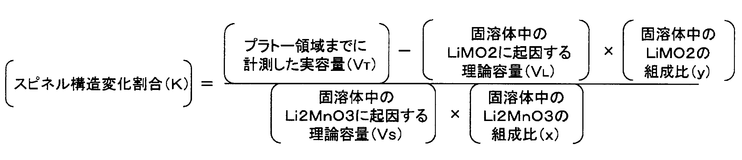
- the “spinel structure change ratio” means that Li 2 MnO 3 having a layered structure in the solid solution lithium-containing transition metal oxide A is converted to LiMn having a spinel structure by performing charging or charging / discharging in a predetermined potential range.
- a defines the percentage change in 2 O 4, a spinel structure change ratio when Li 2 MnO 3 with the layered structure in the solid solution lithium-containing transition metal oxide a is changed all LiMn 2 O 4 having a spinel structure It is set to 1. Specifically, it is defined by the following formula.
- a battery assembled using a positive electrode having a solid solution lithium-containing transition metal oxide A as a positive electrode active material as shown in FIG. A case where charging state B is charged to 5V, overcharge state C is charged to 4.8V after passing through a plateau region, and discharging state D is further discharged to 2.0V will be described as an example.
- the “actual capacity of the plateau region” in the above formula is the plateau region in FIG. 1 (specifically, the region from 4.5 V to 4.8 V (the actual capacity V BC of the region BC from the charged state B to the overcharged state C) .
- the actual capacity of the plateau region which is the region resulting from the change in the crystal structure.
- composition ratio of Li 2 MnO 3 in the solid solution can be calculated from the composition formula of the solid solution lithium-containing transition metal oxide A.
- the presence or absence of the layer structure part and the spinel structure part in the solid solution lithium-containing transition metal oxide A can be determined by the presence of a peculiar peak in the layer structure and the spinel structure by X-ray diffraction analysis (XRD), and the ratio Can be determined from the measurement and calculation of the capacity as described above.
- XRD X-ray diffraction analysis
- the positive electrode active material containing such a solid solution lithium-containing transition metal oxide A can realize an excellent discharge operating voltage and initial rate characteristics while maintaining a higher discharge capacity.
- the solid solution lithium-containing transition metal oxide A in the positive electrode active material of the present embodiment has a BET specific surface area of 0.8 m 2 / g or more and 10.0 m 2 / g or less, and a 50% passing particle size (D50) of 20 ⁇ m or less.
- the primary particle diameter is preferably 30 nm or more and 200 nm or less.
- the outstanding discharge operation voltage and the initial rate characteristic can be implement
- the BET specific surface area is less than 0.8 m 2 / g, the diffusibility of lithium ions from the bulk in the crystal structure becomes low, so that high initial charge / discharge efficiency and excellent initial rate characteristics are realized. May not be possible.
- the capacity retention ratio may be lowered.
- the primary particle diameter is out of the above range, a high discharge capacity may not be obtained.
- a production method using a carbonate method can be mentioned.
- nickel (Ni), cobalt (Co), manganese (Mn) sulfates, nitrates, and the like are used as starting materials, and a predetermined amount is weighed to prepare a mixed solution thereof.
- aqueous ammonia is added dropwise to the mixed solution until pH 7 is reached, and an aqueous solution of sodium carbonate (Na 2 CO 3 ) is further added dropwise to precipitate a composite carbonate of Ni—Co—Mn (Na 2 CO 3).
- aqueous solution While the aqueous solution is being dropped, pH 7 is maintained with aqueous ammonia). Further, it is suction filtered, washed with water, dried, and pre-baked. As drying conditions, it may be dried in the atmosphere at 100 to 150 ° C. for about 2 to 10 hours (for example, 120 ° C. for 5 hours), but is not limited to this range. Pre-baking conditions may be pre-baking in the atmosphere at 360 to 600 ° C. for 3 to 10 hours (eg, 500 ° C. for 5 hours), but are not limited to this range. Furthermore, a small excess of lithium hydroxide (LiOH.H 2 O) is added to the temporarily fired product and mixed.
- LiOH.H 2 O lithium hydroxide
- a precursor of the solid solution lithium-containing transition metal oxide A can be produced.
- rapid cooling is performed using liquid nitrogen. This is because quenching with liquid nitrogen or the like after the main firing is preferable for reactivity and cycle stability.
- the main baking may be performed, for example, in the atmosphere at a baking temperature of 700 to 1000 ° C. (for example, 800 to 900 ° C.) for about 3 to 20 hours (for example, 12 hours).
- the solid solution lithium-containing transition metal oxide A can be obtained by oxidizing the precursor. For example, (1) charging or charging / discharging in a predetermined potential range, specifically, charging or charging / discharging from a low potential region that does not cause a significant change in the crystal structure of the solid solution lithium-containing transition metal oxide from the beginning; 2) Oxidation with an oxidizing agent (for example, halogen such as bromine and chlorine) corresponding to charging, and (3) oxidation treatment such as oxidation with a redox mediator.
- an oxidizing agent for example, halogen such as bromine and chlorine
- the highest potential in the predetermined potential range with respect to the lithium metal counter electrode is 4.3 V or more and 4.8 V or less. It is desirable to perform charging and discharging for 1 to 30 cycles under the conditions. More preferably, it is desirable to perform charging and discharging for 1 to 30 cycles under the condition of 4.4 V or more and 4.6 V or less.
- the upper limit potential is gradually (stepwise) increased after charging / discharging at the initial predetermined upper limit potential.
- the potential converted to the lithium metal or the lithium metal corresponds to a potential based on the potential exhibited by the lithium metal in the electrolytic solution in which 1 mol / L of lithium ions are dissolved.
- the maximum potential in the predetermined potential range for charging and discharging stepwise after 1 to 30 cycles of charging and discharging in the predetermined potential range for the lithium metal counter electrode is desirable to increase.
- the number of cycles required for charging / discharging at each stage when the maximum potential (upper limit potential) of a predetermined charging / discharging potential range is increased stepwise is not particularly limited, but a range of 1 to 10 is effective.
- the total number of charge / discharge cycles in the oxidation process when increasing the maximum potential (upper limit potential) in the predetermined potential range of charge / discharge is not particularly limited, but a range of 4 to 20 times is effective.
- the present invention is not limited to the above range, and oxidation treatment (charge / discharge pretreatment with regulated potential) may be performed up to a higher termination maximum potential as long as the above effects can be achieved.
- the minimum potential in the predetermined potential range is not particularly limited, and is 2 V or more and less than 3.5 V, more preferably 2 V or more and less than 3 V with respect to the lithium metal counter electrode.
- a high discharge capacity and capacity retention ratio can be realized by performing oxidation treatment (charge / discharge pretreatment with a regulated potential) by charging or charging / discharging within the above range.
- the charge / discharge potential (V) refers to a potential per unit cell (unit cell).
- the temperature of the electrode (material) to be charged / discharged as an oxidation treatment can be arbitrarily set as long as it does not impair the effects of the present invention. it can. From the economical point of view, it is desirable to carry out at room temperature that does not require special heating and cooling. On the other hand, it is desirable to carry out at a temperature higher than room temperature from the viewpoint that a larger capacity can be expressed and the capacity retention rate can be improved by a short charge / discharge treatment.
- the step (time) of applying the oxidation treatment (electrochemical pretreatment by charge / discharge with regulated potential) method is not particularly limited.
- such oxidation treatment can be performed in a state in which a battery is configured, or in a configuration corresponding to an electrode or an electrode. That is, any of application in the state of positive electrode active material powder, application by constituting an electrode, and application after assembling a battery together with the negative electrode may be used.
- Application to a battery can be carried out by applying an oxidation treatment condition (electrochemical pretreatment condition by charge / discharge with regulated potential) in consideration of the potential profile of the capacitance of the negative electrode to be combined.
- the battery in the case where the battery is configured, it is superior in that the oxidation treatment of many electrodes can be performed at a time, rather than performing each individual electrode or a configuration corresponding to the electrode.
- the oxidizing agent used in the oxidation method (2) is not particularly limited, and for example, halogen such as bromine and chlorine can be used. These oxidizing agents may be used alone or in combination. Oxidation with an oxidizing agent can be gradually oxidized by, for example, dispersing solid solution fine particles in a solvent in which the solid solution lithium-containing transition metal oxide does not dissolve, and blowing and dissolving the oxidizing agent into the dispersion.
- M is Cr or Al
- x is a value of 0 or more and less than 2.
- the solid solution lithium-containing transition metal oxide B in the positive electrode active material of the present embodiment is 0.2 m 2 / g or more and 3.0 m 2 / g or less, and preferably has a 50% passing particle size of 20 ⁇ m or less. .
- the outstanding discharge operating voltage and the initial rate characteristic can be implement
- the BET specific surface area is less than 0.2 m 2 / g, the diffusibility of lithium ions from the bulk in the crystal structure becomes low, so that high initial charge / discharge efficiency and excellent initial rate characteristics are realized. May not be possible.
- the capacity maintenance ratio may be lowered.
- the solid solution lithium-containing transition metal oxide A and the lithium-containing transition metal oxide B satisfy the relationship of the following formula (3), and further (4). . 0.50 ⁇ M B / (M A + M B ) ⁇ 1.00 (3) 0.75 ⁇ M B / (M A + M B) ⁇ 1.00 ... (4) (In the formulas (3) and (4), M A represents the mass of the solid solution lithium-containing transition metal oxide A, and M B represents the mass of the lithium-containing transition metal oxide B.) By setting it as such a range, the outstanding discharge operating voltage and the initial rate characteristic can be implement
- FIG. 2 is a schematic cross-sectional view showing an example of a lithium ion secondary battery according to an embodiment of the present invention.
- a lithium ion secondary battery is called a laminated lithium ion secondary battery.
- the lithium ion secondary battery 1 of the present embodiment has a configuration in which a battery element 10 to which a positive electrode lead 21 and a negative electrode lead 22 are attached is enclosed in an exterior body 30 formed of a laminate film. have.
- the positive electrode lead 21 and the negative electrode lead 22 are led out in the opposite direction from the inside of the exterior body 30 to the outside.
- the positive electrode lead and the negative electrode lead may be led out in the same direction from the inside of the exterior body toward the outside.
- such a positive electrode lead and a negative electrode lead can be attached to a positive electrode current collector and a negative electrode current collector described later by, for example, ultrasonic welding or resistance welding.
- the positive electrode lead 21 and the negative electrode lead 22 are made of a metal material such as aluminum (Al), copper (Cu), titanium (Ti), nickel (Ni), alloys thereof, stainless steel (SUS), or the like.
- the material is not limited thereto, and a conventionally known material used as a lead for a lithium ion secondary battery can be used.
- the positive electrode lead and the negative electrode lead may be made of the same material or different materials. Further, as in the present embodiment, a separately prepared lead may be connected to a positive electrode current collector and a negative electrode current collector described later, and each positive electrode current collector and each negative electrode current collector described later are extended. The lead may be formed by this. Although not shown, the positive lead and the negative lead taken out from the exterior body do not affect products (for example, automobile parts, especially electronic devices) by contacting with peripheral devices or wiring and causing electric leakage. Thus, it is preferable to coat with a heat-resistant insulating heat-shrinkable tube or the like.
- a current collector plate may be used for the purpose of taking out current outside the battery.
- the current collector plate is electrically connected to a current collector or a lead, and is taken out of a laminate film that is an exterior material of the battery.
- the material which comprises a current collector plate is not specifically limited,
- the well-known highly electroconductive material conventionally used as a current collector plate for lithium ion secondary batteries can be used.
- As a constituent material of the current collector plate for example, metal materials such as aluminum (Al), copper (Cu), titanium (Ti), nickel (Ni), alloys thereof, and stainless steel (SUS) are preferable, and light weight and corrosion resistance. From the viewpoint of high conductivity, aluminum (Al), copper (Cu), and the like are more preferable. Note that the same material may be used for the positive electrode current collector plate and the negative electrode current collector plate, or different materials may be used.
- the exterior body 30 is preferably formed of a film-shaped exterior material from the viewpoints of miniaturization and weight reduction, but is not limited thereto, and the exterior body for a lithium ion secondary battery is not limited thereto.
- the conventionally well-known thing used for the body can be used. That is, a metal can case can also be applied.
- a polymer-metal composite laminate film having excellent thermal conductivity is used from the viewpoint that it has high output and excellent cooling performance and can be suitably used for batteries for large equipment of electric vehicles and hybrid electric vehicles.
- an outer package formed of a three-layer laminated film outer package in which polypropylene as a thermocompression bonding layer, aluminum as a metal layer, and nylon as an outer protective layer are laminated in this order is suitably used.
- the exterior body may be constituted by another structure, for example, a laminate film having no metal material, a polymer film such as polypropylene, or a metal film, instead of the above-described laminate film.
- the general structure of an exterior body can be represented by the laminated structure of an external protective layer / metal layer / thermocompression bonding layer (however, the external protective layer and the thermocompression bonding layer may be composed of a plurality of layers. .)
- the metal layer it is sufficient to function as a moisture-permeable barrier film, and not only aluminum foil, but also stainless steel foil, nickel foil, plated iron foil, etc. can be used, but it is thin and lightweight. Thus, an aluminum foil excellent in workability can be suitably used.
- the structures that can be used as the exterior body are listed in the form of (external protective layer / metal layer / thermocompression layer).
- Terephthalate / unstretched polypropylene polyethylene terephthalate / nylon / aluminum / unstretched polypropylene, polyethylene terephthalate / nylon / aluminum / nylon / unstretched polypropylene, polyethylene terephthalate / nylon / aluminum / nylon / polyethylene, nylon / polyethylene / aluminum / linear Low density polyethylene, polyethylene terephthalate / polyethylene / aluminum / polyethylene terephthalate Low density polyethylene, and a polyethylene terephthalate / nylon / aluminum / low density polyethylene / cast polypropylene.
- the battery element 10 includes a positive electrode 11 having a positive electrode active material layer 11B formed on both main surfaces of the positive electrode current collector 11A, an electrolyte layer 13, and a negative electrode current collector 12A.
- a plurality of negative electrodes 12 each having a negative electrode active material layer 12 ⁇ / b> B formed on the main surface are stacked.
- the negative electrode active material layer 12 ⁇ / b> B formed above faces the electrolyte layer 13. In this way, a plurality of layers are laminated in the order of the positive electrode, the electrolyte layer, and the negative electrode.
- the adjacent positive electrode active material layer 11B, electrolyte layer 13 and negative electrode active material layer 12B constitute one unit cell layer 14. Therefore, the lithium ion secondary battery 1 of the present embodiment has a configuration in which a plurality of single battery layers 14 are stacked and electrically connected in parallel.
- the positive electrode and the negative electrode may have each active material layer formed on one main surface of each current collector.
- the negative electrode current collector 12a located in the outermost layer of the battery element 10 has the negative electrode active material layer 12B formed on only one side.
- an insulating layer for insulating between the adjacent positive electrode current collector and negative electrode current collector may be provided on the outer periphery of the single cell layer.
- Such an insulating layer is preferably formed of a material that retains the electrolyte contained in the electrolyte layer and the like and prevents electrolyte leakage from the outer periphery of the single cell layer.
- general-purpose plastics such as polypropylene (PP), polyethylene (PE), polyurethane (PUR), polyamide resin (PA), polytetrafluoroethylene (PTFE), polyvinylidene fluoride (PVDF), polystyrene (PS), etc.
- thermoplastic olefin rubber can be used. Silicone rubber can also be used.
- the positive electrode current collector 11A and the negative electrode current collector 12A are made of a conductive material.
- the size of the current collector can be determined according to the intended use of the battery. For example, if it is used for a large battery that requires a high energy density, a current collector having a large area is used. There is no particular limitation on the thickness of the current collector.
- the thickness of the current collector is usually about 1 to 100 ⁇ m.
- the shape of the current collector is not particularly limited. In the battery element 10 shown in FIG. 2, in addition to the current collector foil, a mesh shape (expanded grid or the like) can be used.
- a current collection foil In addition, when forming the thin film alloy which is an example of a negative electrode active material directly on the negative electrode collector 12A by sputtering method etc., it is desirable to use a current collection foil.
- the material constituting the current collector there is no particular limitation on the material constituting the current collector.
- a metal or a resin in which a conductive filler is added to a conductive polymer material or a non-conductive polymer material can be employed.
- the metal include aluminum (Al), nickel (Ni), iron (Fe), stainless steel (SUS), titanium (Ti), copper (Cu), and the like.
- covered with aluminum (Al) may be sufficient.
- aluminum (Al), stainless steel (SUS), copper (Cu), and nickel (Ni) are preferable from the viewpoint of electronic conductivity, battery operating potential, and the like.
- the conductive polymer material examples include polyaniline, polypyrrole, polythiophene, polyacetylene, polyparaphenylene, polyphenylene vinylene, polyacrylonitrile, and polyoxadiazole. Since such a conductive polymer material has sufficient conductivity without adding a conductive filler, it is advantageous in terms of facilitating the manufacturing process or reducing the weight of the current collector.
- Non-conductive polymer materials include, for example, polyethylene (PE; high density polyethylene (HDPE), low density polyethylene (LDPE), etc.), polypropylene (PP), polyethylene terephthalate (PET), polyether nitrile (PEN), polyimide (PI), polyamideimide (PAI), polyamide (PA), polytetrafluoroethylene (PTFE), styrene-butadiene rubber (SBR), polyacrylonitrile (PAN), polymethyl acrylate (PMA), polymethyl methacrylate (PMMA) , Polyvinyl chloride (PVC), polyvinylidene fluoride (PVDF), polystyrene (PS), and the like.
- PE polyethylene
- HDPE high density polyethylene
- LDPE low density polyethylene
- PP polypropylene
- PET polyethylene terephthalate
- PEN polyether nitrile
- PI polyimide
- PAI polyamideimide
- PA polyamide
- PTFE polyte
- a conductive filler can be added to the conductive polymer material or the non-conductive polymer material as necessary.
- a conductive filler is inevitably necessary to impart conductivity to the resin.
- the conductive filler can be used without particular limitation as long as it is a substance having conductivity.
- a metal, conductive carbon, etc. are mentioned as a material excellent in electroconductivity, electric potential resistance, or lithium ion interruption
- nickel (Ni), titanium (Ti), aluminum (Al), copper (Cu), platinum (Pt), iron (Fe), chromium (Cr), tin (Sn), zinc (Zn), indium Preferred examples include those containing at least one metal selected from the group consisting of (In), antimony (Sb), and potassium (K), or an alloy or metal oxide containing these metals.
- preferred examples of the conductive carbon include those containing at least one selected from the group consisting of acetylene black, vulcan, black pearl, carbon nanofiber, ketjen black, carbon nanotube, carbon nanohorn, carbon nanoballoon, and fullerene. Can be mentioned.
- the amount of the conductive filler added is not particularly limited as long as it is an amount capable of imparting sufficient conductivity to the current collector, and is generally about 5 to 35% by mass.
- the material is not limited to these, and a conventionally known material used as a current collector for a lithium ion secondary battery can be used.
- the positive electrode active material layer 11B includes the positive electrode active material according to the embodiment of the present invention described above as the positive electrode active material, and may include a binder and a conductive auxiliary as necessary.
- binder Although it does not specifically limit as a binder (binder), the following materials are mentioned. Polyethylene (PE), polypropylene (PP), polyethylene terephthalate (PET), polyether nitrile (PEN), polyacrylonitrile (PAN), polyimide (PI), polyamide (PA), cellulose, carboxymethyl cellulose (CMC), ethylene-acetic acid Vinyl copolymer, polyvinyl chloride (PVC), styrene / butadiene rubber (SBR), isoprene rubber, butadiene rubber, ethylene / propylene rubber, ethylene / propylene / diene copolymer, styrene / butadiene / styrene block copolymer, and Its hydrogenated product, thermoplastic polymer such as styrene / isoprene / styrene block copolymer and its hydrogenated product, polyvinylidene fluoride (PVDF), polytetra
- polyvinylidene fluoride, polyimide, styrene / butadiene rubber, carboxymethyl cellulose, polypropylene, polytetrafluoroethylene, polyacrylonitrile, and polyamide are more preferable.
- These suitable binders are excellent in heat resistance, have a very wide potential window, are stable at both the positive electrode potential and the negative electrode potential, and can be used for the positive electrode (and negative electrode) active material layer.
- the material is not limited to these, and a known material conventionally used as a binder for a lithium ion secondary battery can be used. These binders may be used alone or in combination of two or more.
- the amount of the binder contained in the positive electrode active material layer is not particularly limited as long as it can bind the positive electrode active material, but preferably 0.5 to 15 mass with respect to the positive electrode active material layer. %, More preferably 1 to 10% by mass.
- a conductive support agent is mix
- a conductive support agent carbon materials, such as carbon black, such as acetylene black, a graphite, and a vapor growth carbon fiber, can be mentioned, for example.
- carbon black such as acetylene black, a graphite, and a vapor growth carbon fiber
- the positive electrode active material layer contains a conductive additive, an electronic network inside the positive electrode active material layer is effectively formed, which can contribute to improvement of the output characteristics of the battery.
- the material is not limited to these, and a conventionally known material that is used as a conductive additive for a lithium ion secondary battery can be used.
- These conductive assistants may be used alone or in combination of two or more.
- the conductive binder having the functions of the conductive assistant and the binder may be used in place of the conductive assistant and the binder, or one or both of the conductive assistant and the binder. You may use together.
- the conductive binder for example, commercially available TAB-2 (manufactured by Hosen Co., Ltd.) can be used.
- the density of the positive electrode active material layer is preferably 2.5 g / cm 3 or more and 3.0 g / cm 3 or less.
- the density of the positive electrode active material layer is less than 2.5 g / cm 3 , it is difficult to improve the discharge capacity because the weight (filling amount) per unit volume cannot be improved.
- the density of the positive electrode active material layer exceeds 3.0 g / cm 3 , the amount of voids in the positive electrode active material layer is remarkably reduced, and the permeability of the non-aqueous electrolyte and the lithium ion diffusibility may be reduced. is there.
- the negative electrode active material layer 12B includes, as a negative electrode active material, lithium, a lithium alloy, or a negative electrode material capable of occluding and releasing lithium, and includes a binder and a conductive aid as necessary. May be. In addition, what was demonstrated above can be used for a binder and a conductive support agent.
- Examples of the negative electrode material capable of inserting and extracting lithium include graphite (natural graphite, artificial graphite, etc.), which is highly crystalline carbon, low crystalline carbon (soft carbon, hard carbon), carbon black (Ketjen) Carbon materials such as black, acetylene black, channel black, lamp black, oil furnace black, thermal black), fullerenes, carbon nanotubes, carbon nanofibers, carbon nanohorns, carbon fibrils (containing 10% by mass or less of silicon nanoparticles) Silicon (Si), germanium (Ge), tin (Sn), lead (Pb), aluminum (Al), indium (In), zinc (Zn), hydrogen (H), calcium (Ca), strontium( r), barium (Ba), ruthenium (Ru), rhodium (Rh), iridium (Ir), palladium (Pd), platinum (Pt), silver (Ag), gold (Au), cadmium (Cd), mercury ( Hg), gallium (Ga), thallium (T
- the carbon material is made of a graphite material that is coated with an amorphous carbon layer and is not scale-like, and the BET specific surface area of the carbon material is 0.8 m 2 / g or more and 1.5 m. 2 / g or less and the tap density is preferably 0.9 g / cm 3 or more and 1.2 g / cm 3 or less.
- a carbon material made of a graphite material that is coated with an amorphous carbon layer and is not scale-like is preferable because of its high lithium ion diffusibility into the graphite layered structure.
- the BET specific surface area of such a carbon material is 0.8 m 2 / g or more and 1.5 m 2 / g or less because the capacity retention rate can be further improved. Furthermore, when the tap density of such a carbon material is 0.9 g / cm 3 or more and 1.2 g / cm 3 or less, the weight (filling amount) per unit volume can be improved, and the discharge capacity is improved. be able to.
- the negative electrode active material layer containing at least the carbon material and the binder has a BET specific surface area of 2.0 m 2 / g or more and 3.0 m 2 / g or less.
- the BET specific surface area of the negative electrode active material layer is 2.0 m 2 / g or more and 3.0 m 2 / g or less, the permeability of the non-aqueous electrolyte can be improved, and the capacity retention rate is further improved, Gas generation due to decomposition of the non-aqueous electrolyte can be suppressed.
- the negative electrode active material layer containing at least a carbon material and a binder preferably has a BET specific surface area after pressure molding of 2.01 m 2 / g or more and 3.5 m 2 / g or less. It is.
- the BET specific surface area of the negative electrode active material layer after pressure molding is 2.01 m 2 / g or more and 3.5 m 2 / g or less.
- the increase in the BET specific surface area before and after pressure press molding of the negative electrode active material layer containing at least the carbon material and the binder is 0.01 m 2 / g or more and 0.5 m 2 / g or less. Preferably it is. Since the BET specific surface area after pressure molding of the negative electrode active material layer can be 2.01 m 2 / g or more and 3.5 m 2 / g or less, the permeability of the non-aqueous electrolyte can be improved. The capacity retention rate can be improved and gas generation due to decomposition of the non-aqueous electrolyte can be suppressed.
- each active material layer active material layer on one side of the current collector
- the thickness of each active material layer is not particularly limited, and conventionally known knowledge about the battery can be referred to as appropriate.
- the thickness of each active material layer is usually about 1 to 500 ⁇ m, preferably 2 to 100 ⁇ m, taking into consideration the intended use of the battery (emphasis on output, energy, etc.) and ion conductivity.
- the optimum particle diameter when the optimum particle diameter is different for expressing the unique effect of each active material, the optimum particle diameters may be used in combination for expressing each unique effect. There is no need to make the particle size of the material uniform.
- the average particle size of the oxide when an oxide in the form of particles is used as the positive electrode active material, the average particle size of the oxide may be approximately the same as the average particle size of the positive electrode active material included in the existing positive electrode active material layer, and is not particularly limited. . From the viewpoint of higher output, it is preferably in the range of 1 to 20 ⁇ m.
- the “particle diameter” refers to the outline of active material particles (observation surface) observed using an observation means such as a scanning electron microscope (SEM) or a transmission electron microscope (TEM).
- the value of “average particle size” is the average value of the particle size of particles observed in several to several tens of fields using an observation means such as a scanning electron microscope (SEM) or a transmission electron microscope (TEM). The calculated value shall be adopted.
- the particle diameters and average particle diameters of other components can be defined in the same manner. However, it is not limited to such a range at all, and it goes without saying that it may be outside this range as long as the effects of the present embodiment can be expressed effectively.
- an electrolyte solution for example, an electrolyte solution, a polymer gel electrolyte, a solid polymer electrolyte formed in a separator described later, and a layer structure formed using a solid polymer electrolyte, or a polymer gel electrolyte or a solid polymer electrolyte are used. Examples thereof include those having a laminated structure formed thereon.
- the electrolyte solution is preferably one that is usually used in a lithium ion secondary battery, and specifically has a form in which a supporting salt (lithium salt) is dissolved in an organic solvent.
- a supporting salt lithium salt
- the lithium salt include lithium hexafluorophosphate (LiPF 6 ), lithium tetrafluoroborate (LiBF 4 ), lithium perchlorate (LiClO 4 ), lithium hexafluoroarsenate (LiAsF 6 ), six Inorganic acid anion salts such as lithium fluorotantalate (LiTaF 6 ), lithium tetrachloroaluminate (LiAlCl 4 ), lithium decachlorodecaborate (Li 2 B 10 Cl 10 ), lithium trifluoromethanesulfonate (LiCF 3) Organic acids such as SO 3 ), lithium bis (trifluoromethanesulfonyl) imide (Li (CF 3 SO 2 ) 2
- Examples of the organic solvent include cyclic carbonates, fluorine-containing cyclic carbonates, chain carbonates, fluorine-containing chain carbonates, aliphatic carboxylic acid esters, fluorine-containing aliphatic carboxylic acid esters, and ⁇ -lactone. , Fluorine-containing ⁇ -lactones, cyclic ethers, fluorine-containing cyclic ethers, chain ethers, and at least one organic solvent selected from the group consisting of fluorine-containing chain ethers can be used.
- Examples of cyclic carbonates include propylene carbonate (PC), ethylene carbonate (EC), and butylene carbonate (BC).
- fluoroethylene carbonate FEC
- chain carbonates include dimethyl carbonate (DMC), diethyl carbonate (DEC), ethyl methyl carbonate (EMC), methyl propyl carbonate (MPC), ethyl propyl carbonate (EPC), and dipropyl carbonate (DPC).
- DMC dimethyl carbonate
- DEC diethyl carbonate
- EMC ethyl methyl carbonate
- MPC methyl propyl carbonate
- EPC ethyl propyl carbonate
- DPC dipropyl carbonate
- aliphatic carboxylic acid esters include methyl formate, methyl acetate, and ethyl propionate.
- ⁇ -lactones include ⁇ -butyrolactone.
- cyclic ethers examples include tetrahydrofuran, 2-methyltetrahydrofuran, and 1,4-dioxane.
- chain ethers examples include 1,2-ethoxyethane (DEE), ethoxymethoxyethane (EME), diethyl ether, 1,2-dimethoxyethane, and 1,2-dibutoxyethane.
- DEE 1,2-ethoxyethane
- EME ethoxymethoxyethane
- diethyl ether 1,2-dimethoxyethane
- 1,2-dibutoxyethane 1,2-dibutoxyethane.
- nitriles such as acetonitrile
- amides such as dimethylformamide.
- the electrolyte includes organic sulfone compounds such as sultone derivatives and cyclic sulfonic acid esters, organic disulfone compounds such as disulfone derivatives and cyclic disulfonic acid esters, vinylene carbonate derivatives, ethylene carbonate derivatives, ester derivatives, divalent phenol derivatives, ethylene Additives such as glycol derivatives, terphenyl derivatives, and phosphate derivatives may be added. These form a film on the surface of the negative electrode active material, reduce gas generation in the battery, and further improve the capacity retention rate.
- organic sulfone compound examples include 1,3-propanesulfone (saturated sultone) and 1,3-propene sultone (unsaturated sultone).
- organic disulfone compounds examples include methylene methanedisulfonate.
- vinylene carbonate derivative examples include vinylene carbonate (VC).
- FEC fluoroethylene carbonate
- ester derivatives examples include 4-biphenylyl acetate, 4-biphenylyl benzoate, 4-biphenylyl benzyl carboxylate, and 2-biphenylyl propionate.
- Examples of the dihydric phenol derivative include 1,4-diphenoxybenzene and 1,3-diphenoxybenzene.
- examples of the ethylene glycol derivative include 1,2-diphenoxyethane, 1- (4-biphenylyloxy) -2-phenoxyethane, and 1- (2-biphenylyloxy) -phenoxyethane.
- examples of the terphenyl derivative include o-terphenyl, m-terphenyl, p-terephenyl, 2-methyl-o-terphenyl, and 2,2-dimethyl-o-terphenyl.
- examples of the phosphate derivative include triphenyl phosphate.
- separator examples include a microporous film made of polyolefin such as polyethylene (PE) and polypropylene (PP), a porous flat plate, and a nonwoven fabric.
- PE polyethylene
- PP polypropylene
- polymer gel electrolyte examples include those containing a polymer constituting the polymer gel electrolyte and an electrolytic solution in a conventionally known ratio. For example, from the viewpoint of ionic conductivity, it is desirable that the content be about several mass% to 98 mass%.
- the polymer gel electrolyte is a solid polymer electrolyte having ion conductivity containing the above-described electrolytic solution usually used in a lithium ion secondary battery.
- the present invention is not limited to this, and includes a structure in which a similar electrolyte solution is held in a polymer skeleton having no lithium ion conductivity.
- polymers having no lithium ion conductivity used in the polymer gel electrolyte examples include polyvinylidene fluoride (PVDF), polyvinyl chloride (PVC), polyacrylonitrile (PAN), and polymethyl methacrylate (PMMA). Can be used. However, it is not necessarily limited to these. In addition, since polyacrylonitrile (PAN), polymethyl methacrylate (PMMA), and the like are in a class that has almost no ionic conductivity, it can be a polymer having the ionic conductivity.
- the polymer used for the polymer gel electrolyte is exemplified as a polymer having no lithium ion conductivity.
- the solid polymer electrolyte examples include a structure in which the lithium salt is dissolved in polyethylene oxide (PEO), polypropylene oxide (PPO), and the like, and does not contain an organic solvent. Therefore, when the electrolyte layer is composed of a solid polymer electrolyte, there is no fear of liquid leakage from the battery, and the battery reliability can be improved.
- PEO polyethylene oxide
- PPO polypropylene oxide
- the thickness of the electrolyte layer is preferably thinner from the viewpoint of reducing internal resistance.
- the thickness of the electrolyte layer is usually 1 to 100 ⁇ m, preferably 5 to 50 ⁇ m.
- a polymer gel electrolyte or a solid polymer electrolyte matrix polymer can exhibit excellent mechanical strength by forming a cross-linked structure.
- a suitable polymerization initiator is used to polymerize a polymer for forming a polymer electrolyte (for example, polyethylene oxide (PEO) or polypropylene oxide (PPO)) by thermal polymerization, ultraviolet polymerization, A polymerization treatment such as radiation polymerization or electron beam polymerization may be performed.
- a positive electrode is produced.
- a positive electrode slurry is prepared by mixing the positive electrode active material described above and, if necessary, a conductive additive, a binder, and a viscosity adjusting solvent.
- this positive electrode slurry is applied to a positive electrode current collector, dried, and compression molded to form a positive electrode active material layer.
- a negative electrode For example, when a granular negative electrode active material is used, a negative electrode active material and, if necessary, a conductive additive, a binder, and a viscosity adjusting solvent are mixed to prepare a negative electrode slurry. Thereafter, the negative electrode slurry is applied to a negative electrode current collector, dried, and compression molded to form a negative electrode active material layer.
- the positive electrode lead is attached to the positive electrode
- the negative electrode lead is attached to the negative electrode
- the positive electrode, the separator, and the negative electrode are laminated.
- the laminated product is sandwiched between polymer-metal composite laminate sheets, and the outer peripheral edge except for one side is heat-sealed to form a bag-like outer package.
- a non-aqueous electrolyte containing a lithium salt such as lithium hexafluorophosphate and an organic solvent such as ethylene carbonate is prepared and injected into the interior through the opening of the exterior body, and the opening of the exterior body is thermally melted. Wear and enclose. Thereby, a laminate-type lithium ion secondary battery is completed.
- a positive electrode is produced.
- the above-mentioned solid solution lithium-containing transition metal oxide precursor is mixed with a conductive additive, a binder and a viscosity adjusting solvent as necessary to prepare a positive electrode slurry.
- this positive electrode slurry is applied to a positive electrode current collector, dried, and compression molded to form a positive electrode active material layer.
- a negative electrode For example, when a granular negative electrode active material is used, a negative electrode active material and, if necessary, a conductive additive, a binder, and a viscosity adjusting solvent are mixed to prepare a negative electrode slurry. Thereafter, the negative electrode slurry is applied to a negative electrode current collector, dried, and compression molded to form a negative electrode active material layer.
- the positive electrode lead is attached to the positive electrode
- the negative electrode lead is attached to the negative electrode
- the positive electrode, the separator, and the negative electrode are laminated.
- the laminated product is sandwiched between polymer-metal composite laminate sheets, and the outer peripheral edge except for one side is heat-sealed to form a bag-like outer package.
- a non-aqueous electrolyte containing a lithium salt such as lithium hexafluorophosphate and an organic solvent such as ethylene carbonate is prepared and injected into the interior through the opening of the exterior body, and the opening of the exterior body is thermally melted. Wear and enclose. Furthermore, the predetermined charging or charging / discharging described above is performed, thereby completing a laminated lithium ion secondary battery.
- Example 1 ⁇ Synthesis of Solid Solution Lithium-Containing Transition Metal Oxide A1> The solid solution lithium-containing transition metal oxide A1 was synthesized using a composite carbonate method. Nickel (Ni), cobalt (Co), manganese (Mn) sulfate was used as a starting material, and a 2 mol / L sulfate aqueous solution was prepared. A 2 mol / L sodium carbonate aqueous solution was used as the precipitant, and a 0.2 mol / L ammonia aqueous solution was used as the pH adjuster.
- Nickel (Ni), cobalt (Co), manganese (Mn) sulfate was used as a starting material, and a 2 mol / L sulfate aqueous solution was prepared. A 2 mol / L sodium carbonate aqueous solution was used as the precipitant, and a 0.2 mol / L ammonia aqueous solution was used as the pH adjuster.
- a sodium carbonate aqueous solution was dropped into a composite sulfate aqueous solution stirred with a magnetic stirrer to precipitate the precursor. Thereafter, suction filtration was performed, and the precipitate deposited on the filter paper was dried to obtain a composite hydroxide precursor. Thereafter, the obtained precursor and lithium carbonate are pulverized and mixed at a predetermined molar ratio, calcined at 500 ° C., and finally calcined at 800 ° C. to 1000 ° C. for 12 to 24 hours in the air to obtain a target sample. Obtained.
- the lithium-containing transition metal oxide B1 having a spinel structure was synthesized using a solid phase method.
- Manganese oxide, lithium carbonate, and aluminum hydroxide were used as raw materials, a predetermined amount was weighed, and pulverized and mixed using an agate mortar and pestle. The obtained mixture was fired at 1000 ° C. for 12 hours in the air, and then annealed at 600 ° C. for 10 hours in an oxygen atmosphere to obtain a target sample.
- Positive electrode active material solid solution lithium-containing transition metal oxide A1: 75 parts by mass: lithium-containing transition metal oxide B1: 25 parts by mass
- Conductive aid flake graphite: 2.0 parts by mass: acetylene black: 3.5 parts by mass
- Binder Polyvinylidene fluoride (PVDF): 5.5 parts by mass
- Solvent N-methylpyrrolidone (NMP): 74 parts by mass
- a binder solution was prepared by dissolving 5.5 parts by mass of the binder in 49.5 parts by mass of NMP. Next, 55.0 parts by mass of a binder solution is added to a mixed powder of 5.5 parts by mass of a conductive additive and 100 parts by mass of a positive electrode active material, and a planetary mixer (manufactured by Primics, Hibismix 2P-03 type) is used. After kneading, 24.5 parts by mass of NMP was added to the kneaded product to obtain a slurry for positive electrode (solid content concentration 60% by mass).
- the obtained positive electrode slurry was applied to one side of a current collector made of 20 ⁇ m thick aluminum foil by a bar coater. Next, the current collector coated with the positive electrode slurry was dried on a hot plate at 120 to 130 ° C. for 10 minutes, so that the amount of NMP remaining in the positive electrode active material layer was 0.02 mass% or less.
- ⁇ Positive electrode press> The obtained sheet-like positive electrode is compression-molded using a roll press, cut, and a positive electrode active material layer on one side having a weight of about 3.5 mg / cm 2 , a thickness of about 50 ⁇ m, and a density of 2.70 g / cm 3 C1 was obtained.
- ⁇ Drying the positive electrode> a drying process was performed in a vacuum drying furnace. After the positive electrode C1 was placed inside the drying furnace, the pressure in the room was reduced (100 mmHg (1.33 ⁇ 10 4 Pa)) at room temperature (25 ° C.) to remove the air in the drying furnace. Next, while circulating nitrogen gas (100 cm 3 / min), the temperature was raised to 120 ° C. at 10 ° C./min, the pressure was reduced again at 120 ° C., and the nitrogen in the furnace was kept evacuated for 12 hours, and then to room temperature. The temperature was lowered to obtain a positive electrode C11.
- this negative electrode, separator, and positive electrode laminate was placed on the bottom side of a coin cell (CR2032, material: stainless steel (SUS316)). Furthermore, by attaching a gasket to maintain the insulation between the positive electrode and the negative electrode, injecting 150 ⁇ L of the following electrolyte using a syringe, laminating the spring and spacer, and overlapping and caulking the upper side of the coin cell Sealed to produce a lithium ion secondary battery.
- LiPF 6 LiPF 6
- the concentration was used dissolved at a 1 mol / L. No special additives were added to the electrolyte. Thereafter, the battery element was set on an evaluation cell attachment jig, and a positive electrode lead and a negative electrode lead were attached to each tab end portion of the battery element to perform a test.
- CCCV constant current constant voltage charging
- CC constant current discharge
- Example 2 In the composition of the positive electrode slurry, the same operation as in Example 1 was repeated except that 50 parts by mass of the solid solution lithium-containing transition metal oxide A1 and 50 parts by mass of the lithium-containing transition metal oxide B1 were repeated. A lithium ion secondary battery was obtained.
- Example 3 In the composition of the positive electrode slurry, the same operation as in Example 1 was repeated except that 25 parts by mass of the solid solution lithium-containing transition metal oxide A1 and 75 parts by mass of the lithium-containing transition metal oxide B1 were repeated. A lithium ion secondary battery was obtained.
- Example 4 ⁇ Synthesis of transition metal oxide A2 containing solid solution lithium>
- the solid solution lithium-containing transition metal oxide A2 was synthesized using the same composite carbonate method as the transition metal oxide A1 synthesized in Example 1 above.
- Example 2 In the composition of the positive electrode slurry, the same operation as in Example 1 was repeated except that 75 parts by mass of the solid solution lithium-containing transition metal oxide A2 and 25 parts by mass of the lithium-containing transition metal oxide B1 were repeated. A lithium ion secondary battery was obtained.
- Example 5 In the composition of the positive electrode slurry, the same operation as in Example 1 was repeated except that 50 parts by mass of the solid solution lithium-containing transition metal oxide A2 and 50 parts by mass of the lithium-containing transition metal oxide B1 were repeated. A lithium ion secondary battery was obtained.
- Example 6 In the composition of the positive electrode slurry, the same operation as in Example 1 was repeated except that the solid solution lithium-containing transition metal oxide A2 was 25 parts by mass and the lithium-containing transition metal oxide B1 was 75 parts by mass. A lithium ion secondary battery was obtained.
- Example 1 In the composition of the positive electrode slurry, the same operation as in Example 1 was repeated except that the solid solution lithium-containing transition metal oxide A1 was changed to 100 parts by mass to obtain a lithium ion secondary battery of this example.
- Comparative Example 2 In the composition of the positive electrode slurry, the same operation as in Example 1 was repeated except that the solid solution lithium-containing transition metal oxide A2 was changed to 100 parts by mass to obtain a lithium ion secondary battery of this example.
- Example 3 The lithium ion secondary battery of this example was obtained by repeating the same operation as in Example 1 except that the composition of the positive electrode slurry was changed to 100 parts by mass of the lithium-containing transition metal oxide B1.
- Table 2 shows a part of the specifications of the positive electrode active material in each of the above examples.
- Examples 1 to 6 belonging to the scope of the present invention have excellent discharge operating voltage and initial value while maintaining a high discharge capacity as compared with Comparative Examples 1 to 3 outside the present invention. It can be seen that rate characteristics can be realized.
- subjected "*" shows what has improved from the arithmetic average value according to the mixing ratio calculated
- disassembling the lithium ion secondary battery of each example it is a layered structure site
- the solid solution lithium-containing transition metal oxide B taken out by disassembling the lithium ion secondary battery of each example has a spinel structure due to the presence of a peak specific to the spinel structure by X-ray diffraction analysis (XRD). confirmed.
- the structure may be confirmed by electron diffraction analysis, and the composition can be confirmed by, for example, inductively coupled plasma (ICP).
- ICP inductively coupled plasma
- the lithium ion secondary battery a laminate type battery or a coin type battery is exemplified, but the present invention is not limited to this, and a sheet type battery, a button type battery, a square shape or a cylindrical shape is not limited thereto. It can also be applied to a conventionally known form / structure such as a can-type battery.
- the present invention can be applied not only to the above-described stacked (flat) battery but also to a conventionally known form / structure such as a wound (cylindrical) battery.
- the present invention is not only the above-described normal type (internal parallel connection type) battery but also a bipolar type (internal series connection) when viewed in terms of electrical connection form (electrode structure) in a lithium ion secondary battery. It can also be applied to conventionally known forms and structures such as type) batteries.
- a battery element in a bipolar battery generally has a bipolar electrode in which a negative electrode active material layer is formed on one surface of a current collector and a positive electrode active material layer is formed on the other surface, and an electrolyte layer. A plurality of layers.
- the lithium ion secondary battery has been described as an example of the electric device, but the present invention is not limited to this, and the present invention may be applied to a lithium ion capacitor or the like. it can.
Abstract
Description
さらに詳細には、本発明の電気デバイスは、例えば、電気自動車、燃料電池自動車、ハイブリッド電気自動車等の車両用電気デバイスとして好適に用いられる。また、本発明の正極活物質は、通常、電気デバイスとしてのリチウムイオン二次電池やリチウムイオンキャパシタの正極活物質として好適に用いられる。
そして、本発明の正極活物質における固溶体リチウム含有遷移金属酸化物Aは、組成式(1)
Li1.5[NiaCobMnc[Li]d]O3 …(1)
(式(1)中、Liはリチウム、Niはニッケル、Coはコバルト、Mnはマンガン、Oは酸素を示し、a、b、c及びdは、0.2≦a≦0.7、0<b<0.7、0<c<1.2、0.1<d≦0.4、a+b+c+d=1.5、1.1≦a+b+c<1.4、0<b/a<1の関係を満足する。)で表される。
一方、本発明の正極活物質におけるリチウム含有遷移金属酸化物Bは、組成式(2)
LiMXMn2-XO4 …(2)
(式(2)中、Liはリチウム、Mnはマンガン、Oは酸素、MはCr又はAlを示し、xは、0≦x<2の関係を満足する。)で表される。
また、本発明の電気デバイスは、本発明の上記電気デバイス用正極を有するものである。
本実施形態の正極活物質は、固溶体リチウム含有遷移金属酸化物Aとリチウム含有遷移金属酸化物Bとを含有する正極活物質である。
そして、本実施形態の正極活物質における固溶体リチウム含有遷移金属酸化物Aは、組成式(1)で表される。
Li1.5[NiaCobMnc[Li]d]O3 …(1)
(式(1)中、Liはリチウム、Niはニッケル、Coはコバルト、Mnはマンガン、Oは酸素を示し、a、b、c及びdは、0.2≦a≦0.7、0<b<0.7、0<c<1.2、0.1<d≦0.4、a+b+c+d=1.5、1.1≦a+b+c<1.4、0<b/a<1の関係を満足する。)
また、本実施形態の正極活物質における固溶体リチウム含有遷移金属酸化物Aは、4.3V以上4.8V以下の電位範囲における充電又は充放電を行うことによりスピネル構造に変化する層状構造部位と、変化しない層状構造部位とを有する。
さらに、本実施形態の正極活物質における固溶体リチウム含有遷移金属酸化物Aは、変化する層状構造部位のLi2MnO3がスピネル構造のLiMn2O4に全て変化した場合のスピネル構造変化割合を1としたとき、スピネル構造変化割合が0.25以上1.0未満である。
LiMXMn2-XO4 …(2)
(式(2)中、Liはリチウム、Mnはマンガン、Oは酸素、MはCr又はAlを示し、xは、0≦x<2の関係を満足する。)で表され、スピネル構造を有する。
なお、「充電」とは、連続的又は段階的に電極間の電位差を大きくする操作のことをいう。また、「充放電」とは、連続的又は段階的に電極間の電位差を大きくする操作の後に、連続的又は段階的に電極間の電位差を小さくする操作、又はこれを適宜繰り返す操作のことをいう。
また、固溶体リチウム含有遷移金属酸化物Aにおいて、4.3V以上4.8V以下の電位範囲における充電又は充放電を行うことによりスピネル構造に変化する層状構造部位や変化しない層状構造部位を有さない場合には、高い放電容量と容量維持率を実現し得るものとならない。具体的には、4.5V付近の電位プラトー区間以上まで1回以上曝すことが重要である。
さらに、固溶体リチウム含有遷移金属酸化物Aにおいて、上述のスピネル構造変化割合がスピネル構造変化割合が1.0となることはなく、0.25未満である場合には、高い放電容量や容量維持率、優れた初期レート特性を実現し得るものとならない。

特に、4.7V、4.8Vvs.Liという高電位の容量分まで使用(高容量使用)する場合において、酸化処理での充放電電位の最高電位を段階的に上げていくことで、短時間の酸化処理(上記充放電前処理)でも電極の耐久性を改善することができる。
このとき、xは0を超え、0.5未満の範囲の値であることが望ましく、これによってスピネル構造をより安定化することができる。
このような範囲とすることにより、高い放電容量や充放電効率を維持しつつ、優れた放電作動電圧及び初期レート特性を実現し得る。例えば、BET比表面積が0.2m2/g未満の場合には、結晶構造におけるバルク内からのリチウムイオンの拡散性が低くなるため、高い初期充放電効率や優れた初期レート特性を実現することができないことがある。また、例えば、BET比表面積が3.0m2/g超であり、50%通過粒径が20μm超である場合には、容量維持率が低下することがある。
0.50≦MB/(MA+MB)<1.00 …(3)
0.75≦MB/(MA+MB)<1.00 …(4)
(式(3)、(4)中、MAは固溶体リチウム含有遷移金属酸化物Aの質量、MBはリチウム含有遷移金属酸化物Bの質量を示す。)
このような範囲とすることにより、より高い放電容量を維持しつつ、優れた放電作動電圧及び初期レート特性を実現し得る。また、初期充放電効率も優れたものとなる。
なお、負極活物質の一例である薄膜合金をスパッタ法等により負極集電体12A上に直接形成する場合には、集電箔を用いるのが望ましい。
具体的には、金属としては、アルミニウム(Al)、ニッケル(Ni)、鉄(Fe)、ステンレス鋼(SUS)、チタン(Ti)、銅(Cu)などが挙げられる。これらのほか、ニッケル(Ni)とアルミニウム(Al)とのクラッド材、銅(Cu)とアルミニウム(Al)とのクラッド材、又はこれらの金属を組み合わせためっき材などを用いることが好ましい。また、金属表面にアルミニウム(Al)が被覆された箔であってもよい。中でも、電子伝導性や電池作動電位等の観点からは、アルミニウム(Al)、ステンレス鋼(SUS)、銅(Cu)、ニッケル(Ni)が好ましい。
しかしながら、これらに限定されるものではなく、リチウムイオン二次電池用の集電体として用いられている従来公知の材料を用いることができる。
ポリエチレン(PE)、ポリプロピレン(PP)、ポリエチレンテレフタレート(PET)、ポリエーテルニトリル(PEN)、ポリアクリロニトリル(PAN)、ポリイミド(PI)、ポリアミド(PA)、セルロース、カルボキシメチルセルロース(CMC)、エチレン-酢酸ビニル共重合体、ポリ塩化ビニル(PVC)、スチレン・ブタジエンゴム(SBR)、イソプレンゴム、ブタジエンゴム、エチレン・プロピレンゴム、エチレン・プロピレン・ジエン共重合体、スチレン・ブタジエン・スチレンブロック共重合体及びその水素添加物、スチレン・イソプレン・スチレンブロック共重合体及びその水素添加物などの熱可塑性高分子、ポリフッ化ビニリデン(PVDF)、ポリテトラフルオロエチレン(PTFE)、テトラフルオロエチレン・ヘキサフルオロプロピレン共重合体(FEP)、テトラフルオロエチレン・パーフルオロアルキルビニルエーテル共重合体(PFA)、エチレン・テトラフルオロエチレン共重合体(ETFE)、ポリクロロトリフルオロエチレン(PCTFE)、エチレン・クロロトリフルオロエチレン共重合体(ECTFE)、ポリフッ化ビニル(PVF)等のフッ素樹脂、ビニリデンフルオライド-ヘキサフルオロプロピレン系フッ素ゴム(VDF-HFP系フッ素ゴム)、ビニリデンフルオライド-ヘキサフルオロプロピレン-テトラフルオロエチレン系フッ素ゴム(VDF-HFP-TFE系フッ素ゴム)、ビニリデンフルオライド-ペンタフルオロプロピレン系フッ素ゴム(VDF-PFP系フッ素ゴム)、ビニリデンフルオライド-ペンタフルオロプロピレン-テトラフルオロエチレン系フッ素ゴム(VDF-PFP-TFE系フッ素ゴム)、ビニリデンフルオライド-パーフルオロメチルビニルエーテル-テトラフルオロエチレン系フッ素ゴム(VDF-PFMVE-TFE系フッ素ゴム)、ビニリデンフルオライド-クロロトリフルオロエチレン系フッ素ゴム(VDF-CTFE系フッ素ゴム)等のビニリデンフルオライド系フッ素ゴム、エポキシ樹脂等が挙げられる。中でも、ポリフッ化ビニリデン、ポリイミド、スチレン・ブタジエンゴム、カルボキシメチルセルロース、ポリプロピレン、ポリテトラフルオロエチレン、ポリアクリロニトリル、ポリアミドであることがより好ましい。これらの好適なバインダーは、耐熱性に優れ、さらに電位窓が非常に広く正極電位、負極電位双方に安定であり正極(及び負極)活物質層に使用が可能である。
しかしながら、これらに限定されるものではなく、リチウムイオン二次電池用の結着剤として従来用いられている公知の材料を用いることができる。これらの結着剤は、1種のみを単独で用いてもよく、2種以上を併用してもよい。
しかしながら、これらに限定されるものではなく、リチウムイオン二次電池用の導電助剤として用いられている従来公知の材料を用いることができる。これらの導電助剤は、1種のみを単独で用いてもよく、2種以上を併用してもよい。
例えば、正極活物質として粒子形態の酸化物を用いる場合、酸化物の平均粒子径は、既存の正極活物質層に含まれる正極活物質の平均粒子径と同程度であればよく、特に制限されない。高出力化の観点からは、好ましくは1~20μmの範囲であればよい。なお、本明細中において、「粒子径」とは、走査型電子顕微鏡(SEM)や透過型電子顕微鏡(TEM)などの観察手段を用いて観察される活物質粒子(観察面)の輪郭線上の任意の2点間の距離のうち、最大の距離を意味する。「平均粒子径」の値としては、走査型電子顕微鏡(SEM)や透過型電子顕微鏡(TEM)などの観察手段を用い、数~数十視野中に観察される粒子の粒子径の平均値として算出される値を採用するものとする。他の構成成分の粒子径や平均粒子径も同様に定義することができる。
ただし、このような範囲に何ら制限されるものではなく、本実施形態の作用効果を有効に発現できるものであれば、この範囲を外れていてもよいことは言うまでもない。
環状カーボネート類としては、例えば、プロピレンカーボネート(PC)、エチレンカーボネート(EC)、ブチレンカーボネート(BC)を挙げることができる。また、含フッ素環状カーボネート類としては、例えば、フルオロエチレンカーボネート(FEC)を挙げることができる。更に、鎖状カーボネート類としては、例えば、ジメチルカーボネート(DMC)、ジエチルカーボネート(DEC)、エチルメチルカーボネート(EMC)、メチルプロピルカーボネート(MPC)、エチルプロピルカーボネート(EPC)、ジプロピルカーボネート(DPC)を挙げることができる。また、脂肪族カルボン酸エステル類としては、例えば、ギ酸メチル、酢酸メチル、プロピオン酸エチルを挙げることができる。更に、γ-ラクトン類としては、例えば、γ-ブチロラクトンを挙げることができる。また、環状エーテル類としては、例えば、テトラヒドロフラン、2-メチルテトラヒドロフラン、1,4-ジオキサンを挙げることができる。更に、鎖状エーテル類としては、例えば、1,2-エトキシエタン(DEE)、エトキシメトキシエタン(EME)、ジエチルエーテル、1,2-ジメトキシエタン、1,2-ジブトキシエタンを挙げることができる。その他としては、アセトニトリル等のニトリル類、ジメチルホルムアミド等のアミド類を挙げることができる。これらは、1種を単独で、2種以上を組み合わせて用いることができる。
高分子ゲル電解質は、イオン導伝性を有する固体高分子電解質に、通常リチウムイオン二次電池で用いられる上記電解液を含有させたものである。しかしながら、これに限定されるものではなく、リチウムイオン導伝性を持たない高分子の骨格中に、同様の電解液を保持させたものも含まれる。
なお、高分子ゲル電解質や固体高分子電解質のマトリックスポリマーは、架橋構造を形成することによって、優れた機械的強度を発現させることができる。架橋構造を形成させるには、適当な重合開始剤を用いて、高分子電解質形成用の重合性ポリマー(例えば、ポリエチレンオキシド(PEO)やポリプロピレンオキシド(PPO))に対して熱重合、紫外線重合、放射線重合、電子線重合等の重合処理を施せばよい。
リチウムイオン二次電池の製造方法の一例を説明する。まず、正極を作製する。例えば粒状の正極活物質を用いる場合には、上述した正極活物質と必要に応じて導電助剤、バインダー及び粘度調整溶剤とを混合し、正極用スラリーを作製する。
次いで、この正極用スラリーを正極集電体に塗布し、乾燥させ、圧縮成型して正極活物質層を形成する。
次いで、この正極用スラリーを正極集電体に塗布し、乾燥させ、圧縮成型して正極活物質層を形成する。
<固溶体リチウム含有遷移金属酸化物A1の合成>
固溶体リチウム含有遷移金属酸化物A1は複合炭酸塩法を用いて合成した。出発物質にはニッケル(Ni)、コバルト(Co)、マンガン(Mn)の硫酸塩を使用し、2mol/Lの硫酸塩水溶液を調製した。沈殿剤には2mol/Lの炭酸ナトリウム水溶液を使用し、pH調整剤には0.2mol/Lのアンモニア水溶液を用いた。
マグネチックスターラーで攪拌されている複合硫酸塩水溶液に炭酸ナトリウム水溶液を滴下して前躯体を沈殿させた。その後、吸引ろ過を行い、ろ紙上に堆積した沈殿物を乾燥することにより、複合水酸化物の前駆体を得た。
その後、得られた前駆体と炭酸リチウムを所定のモル比で粉砕混合し、500℃で仮焼成し、大気中、800℃~1000℃で12時間~24時間本焼成することにより目的の試料を得た。
スピネル構造を有するリチウム含有遷移金属酸化物B1は固相法を用いて合成した。原料にはマンガン酸化物、炭酸リチウム、水酸化アルミニウムを用い、所定量を秤量し、メノウ乳鉢と乳棒を使用して粉砕混合した。得られた混合物は大気中1000℃で12時間焼成後、酸素雰囲気下で600℃、10時間アニール処理し目的の試料を得た。
組成式:Li1.5[Ni0.42Co0.15Mn0.73[Li]0.2]O3
(a+b+c+d=1.5、d=0.20、a+b+c=1.30、b/a=0.357)
組成式:LiAl0.1Mn1.9O4
(x=0.1)
正極活物質:固溶体リチウム含有遷移金属酸化物A1:75質量部
:リチウム含有遷移金属酸化物B1 :25質量部
導電助剤 :燐片状黒鉛 :2.0質量部
:アセチレンブラック :3.5質量部
バインダー:ポリフッ化ビニリデン(PVDF) :5.5質量部
溶剤 :N-メチルピロリドン(NMP) :74質量部
バインダー5.5質量部をNMP49.5質量部に溶解してバインダー溶液を作製した。次に、導電助剤5.5質量部と正極活物質100質量部の混合粉に、バインダー溶液55.0質量部を加え、プラネタリーミキサー(プライミクス社製、ハイビスミックス2P-03型)にて混練し、その後、混練物にNMP24.5質量部を加えて、正極用スラリー(固形分濃度60質量%)を得た。
20μm厚のアルミニウム箔からなる集電体の片面に、得られた正極用スラリーをバーコーターにより塗布した。次いで、この正極用スラリーを塗布した集電体を、ホットプレート上で、120~130℃で10分間乾燥させ、正極活物質層に残留するNMP量を0.02質量%以下とした。
得られたシート状正極をロールプレスを用いて圧縮成形し、切断して、片面の正極活物質層の重量約3.5mg/cm2、厚さ約50μm、密度2.70g/cm3の正極C1を得た。
次に、この正極C1を用い、真空乾燥炉にて乾燥処理を行った。乾燥炉内部に正極C1を設置した後、室温(25℃)にて減圧(100mmHg(1.33×10⁴Pa))し、乾燥炉内の空気を除去した。次いで、窒素ガスを流通(100cm3/分)しながら、10℃/分で120℃まで昇温し、120℃で再度減圧して炉内の窒素を排気したまま12時間保持した後、室温まで降温して、正極C11を得た。
実施例1で作製した正極C11をφ15mmに打ち抜いた後、再度、電池作製前に真空乾燥機にて100℃で2時間乾燥して用いた。また、ポリプロピレンの多孔質膜やコインセル部材などは、予め、アルゴンガス雰囲気のグローブボックス内にて室温で24時間以上乾燥して用いた。
アルゴンガス雰囲気のグローブボックス内にて、正極と、金属リチウムからなる負極とを対向させ、この間に、セパレータ(材質:ポリプロピレン、厚み:20μm)を2枚配置した。
次いで、この負極、セパレータ、正極の積層体をコインセル(CR2032、材質:ステンレス鋼(SUS316))の底部側に配置した。
さらに、正極と負極の間の絶縁性を保つためにガスケットを装着し、下記電解液をシリンジを用いて150μL注入し、スプリング及びスペーサーを積層し、コインセルの上部側を重ね合わせ、かしめることにより密閉して、リチウムイオン二次電池を作製した。
なお、電解液としては、エチレンカーボネート(EC)及びジエチルカーボネート(DEC)を、EC:DEC=1:2(体積比)の割合で混合した有機溶媒に、支持塩としての六フッ化リン酸リチウム(LiPF6)を濃度が1mol/Lとなるように溶解させたものを用いた。電解液へ特殊な添加剤等は添加しなかった。
その後、上記電池素子を評価セル取り付け冶具にセットし、正極リードと負極リードを電池素子の各タブ端部に取り付け、試験を行った。
充電は、電池の最高電圧が4.2Vとなるまで0.1Cレートで充電した後、約24時間保持する定電流定電圧充電(CCCV)法とし、放電は、電池の最低電圧が2.5Vとなるまで1.0Cレートで放電する定電流放電(CC)法で行った。
次に、表1に示すように、最高電圧が4.5Vとなるまで0.1Cレートで充電した後、最低電圧が2.0Vとなるまで0.1Cレートで放電する定電流充放電サイクルを2回、最高電圧が4.6Vとなるまで0.1Cレートで充電した後、最低電圧が2.0Vとなるまで0.1Cレートで放電する定電流充放電サイクルを1回、最高電圧が4.7Vとなるまで0.1Cレートで充電した後、最低電圧が2.0Vとなるまで0.1Cレートで放電する定電流充放電サイクルを1回、最高電圧が4.8Vとなるまで0.1Cレートで充電した後、最低電圧が2.0Vとなるまで0.1Cレートで放電する定電流充放電サイクルを1回、最高電圧が4.8Vとなるまで0.1Cレートで定電流定電圧充電した後、最低電圧が2.0Vとなるまで0.1Cレートで定電流放電するサイクルを1回行った。いずれも、室温下で行った。このようにして、本例のリチウムイオン二次電池を得た。
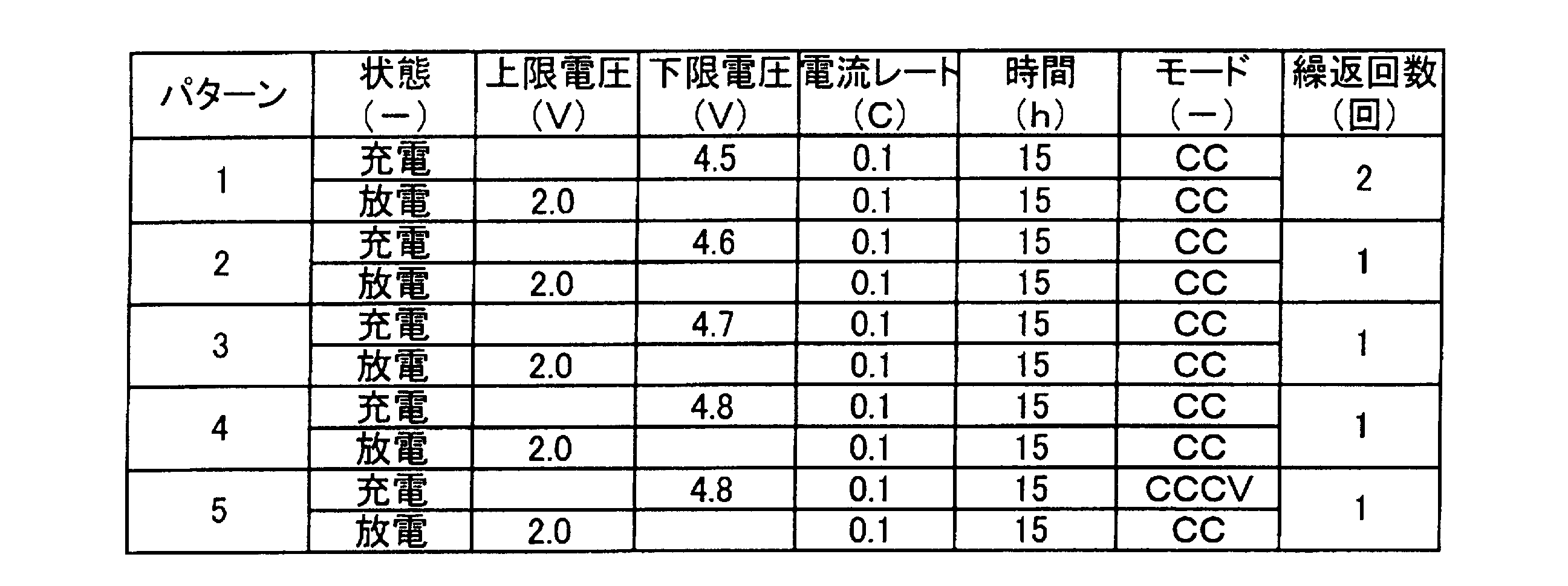
正極用スラリーの組成において、固溶体リチウム含有遷移金属酸化物A1を50質量部、リチウム含有遷移金属酸化物B1を50質量部としたこと以外は、実施例1と同様の操作を繰り返して、本例のリチウムイオン二次電池を得た。
正極用スラリーの組成において、固溶体リチウム含有遷移金属酸化物A1を25質量部、リチウム含有遷移金属酸化物B1を75質量部としたこと以外は、実施例1と同様の操作を繰り返して、本例のリチウムイオン二次電池を得た。
<固溶体リチウム含有遷移金属酸化物A2の合成>
固溶体リチウム含有遷移金属酸化物A2を上記実施例1において合成した遷移金属酸化物A1と同様の複合炭酸塩法を用いて合成した。
組成式:Li1.5[Ni0.4375Co0.175Mn0.7375[Li]0.15]O3
(a+b+c+d=1.5、d=0.15、a+b+c=1.35)
正極用スラリーの組成において、固溶体リチウム含有遷移金属酸化物A2を50質量部、リチウム含有遷移金属酸化物B1を50質量部としたこと以外は、実施例1と同様の操作を繰り返して、本例のリチウムイオン二次電池を得た。
正極用スラリーの組成において、固溶体リチウム含有遷移金属酸化物A2を25質量部、リチウム含有遷移金属酸化物B1を75質量部としたこと以外は、実施例1と同様の操作を繰り返して、本例のリチウムイオン二次電池を得た。
正極用スラリーの組成において、固溶体リチウム含有遷移金属酸化物A1を100質量部としたこと以外は、実施例1と同様の操作を繰り返して、本例のリチウムイオン二次電池を得た。
正極用スラリーの組成において、固溶体リチウム含有遷移金属酸化物A2を100質量部としたこと以外は、実施例1と同様の操作を繰り返して、本例のリチウムイオン二次電池を得た。
正極用スラリーの組成において、リチウム含有遷移金属酸化物B1を100質量部としたこと以外は、実施例1と同様の操作を繰り返して、本例のリチウムイオン二次電池を得た。上記各例の正極活物質の仕様の一部を表2に示す。

(電池の放電容量及び平均電圧)
上記各例のリチウムイオン二次電池に対して、表3に示すように、最高電圧が4.8Vとなるまで0.1Cレートで定電流定電圧充電した後、最低電圧が2.0Vとなるまで0.1Cレートで定電流放電するサイクルを2回行った。このとき、電池の放電容量と平均電圧とを測定、算出した。なお、本発明においては、放電作動電圧を平均電圧により評価することとした。得られた結果を表2に併記する。

また、上記各例のリチウムイオン二次電池に対して、電気化学前処理及び本充放電サイクルにおいて充電容量や放電容量を測定した。このとき、電気化学前処理における充放電サイクルにおける充電容量の差分及び本充放電サイクルにおける充電容量の差分及び最後の充電における充電容量の総和に対する本充放電サイクルにおける最後の放電における放電容量の割合から充放電効率を算出した。得られた結果を表2に併記する。
このとき、各レートにおける電池の放電容量を測定し、容量維持率を算出し、0.1Cレートにおける容量維持率に対する2.5Cレートにおける容量維持率の割合から初期レート特性を算出した。得られた結果を表2に併記する。
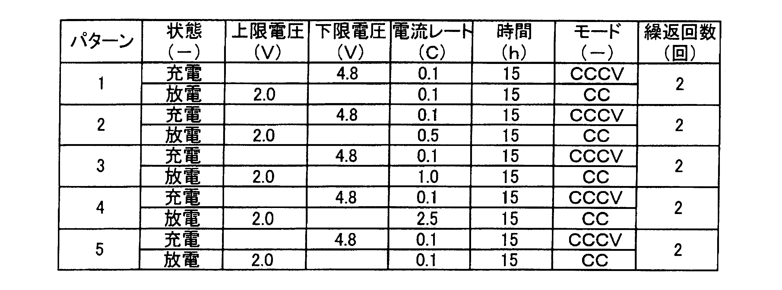
また、各例のリチウムイオン二次電池を分解して取り出した固溶体リチウム含有遷移金属酸化物Bについては、X線回折分析(XRD)よるスピネル構造に特異なピークの存在によりスピネル構造を有することを確認した。なお、構造については、電子線回折分析によって確認してもよく、組成については、例えば誘導結合プラズマ(ICP)によって確認することができる。
Claims (10)
- 組成式(1)
Li1.5[NiaCobMnc[Li]d]O3 …(1)
(式(1)中、Liはリチウム、Niはニッケル、Coはコバルト、Mnはマンガン、Oは酸素を示し、a、b、c及びdは、0.2≦a≦0.7、0<b<0.7、0<c<1.2、0.1<d≦0.4、a+b+c+d=1.5、1.1≦a+b+c<1.4、0<b/a<1の関係を満足する。)で表される固溶体リチウム含有遷移金属酸化物Aと、
組成式(2)
LiMXMn2-XO4 …(2)
(式(2)中、Liはリチウム、Mnはマンガン、Oは酸素、MはCr又はAlを示し、xは、0≦x<2の関係を満足する。)で表されるリチウム含有遷移金属酸化物Bと
を含有する正極活物質。 - 上記固溶体リチウム含有遷移金属酸化物Aと上記リチウム含有遷移金属酸化物Bとが、下記式(3)の関係を満足する請求項1に記載の正極活物質。
0.50≦MB/(MA+MB)<1.00 …(3)
(式(3)中、MAは固溶体リチウム含有遷移金属酸化物Aの質量、MBはリチウム含有遷移金属酸化物Bの質量を示す。) - 上記固溶体リチウム含有遷移金属酸化物Aと上記リチウム含有遷移金属酸化物Bとが、下記式(4)の関係を満足する請求項1又は2に記載の正極活物質。
0.75≦MB/(MA+MB)<1.00 …(4)
(式(4)中、MAは固溶体リチウム含有遷移金属酸化物Aの質量、MBはリチウム含有遷移金属酸化物Bの質量を示す。) - 上記固溶体リチウム含有遷移金属酸化物Aは、上記式(1)において、a、b、c及びdが、0.25<a<0.44、0<b<0.44、0.37<b<1.1、0.15≦d≦0.25、a+b+c+d=1.5、1.25≦a+b+c≦1.35、0<b/a<1の関係を満足すると共に、上記スピネル構造変化割合が0.5%以上0.9未満である
請求項1~3のいずれか1つの項に記載の正極活物質。 - 上記リチウム含有遷移金属酸化物Bは、上記式(2)において、xが、0<x<0.5の関係を満足する
請求項1~4のいずれか1つの項に記載の正極活物質。 - 上記固溶体リチウム含有遷移金属酸化物AのBET比表面積が0.8m2/g以上10.0m2/g以下であり、
上記固溶体リチウム含有遷移金属酸化物Aの50%通過粒径が20μm以下であり、
上記固溶体リチウム含有遷移金属酸化物Aの一次粒子径が30nm以上200nm以下である
請求項1~5のいずれか1つの項に記載の正極活物質。 - 上記リチウム含有遷移金属酸化物BのBET比表面積が0.2m2/g以上3.0m2/g以下であり、
上記リチウム含有遷移金属酸化物Bの50%通過粒径が20μm以下である
請求項1~6のいずれか1つの項に記載の正極活物質。 - 請求項1~7のいずれか1つの項に記載の正極活物質を含む電気デバイス用正極。
- 請求項8に記載の電気デバイス用正極を有する電気デバイス。
- 上記電気デバイスがリチウムイオン二次電池である請求項8に記載の電気デバイス。
Priority Applications (4)
| Application Number | Priority Date | Filing Date | Title |
|---|---|---|---|
| EP13757122.0A EP2824737B1 (en) | 2012-03-07 | 2013-03-06 | Positive electrode active material, positive electrode for electrical device, and electrical device |
| US14/381,399 US9646734B2 (en) | 2012-03-07 | 2013-03-06 | Positive electrode active material, positive electrode for electrical device, and electrical device |
| KR1020147024452A KR101674278B1 (ko) | 2012-03-07 | 2013-03-06 | 정극 활물질, 전기 디바이스용 정극 및 전기 디바이스 |
| CN201380012547.7A CN104160534B (zh) | 2012-03-07 | 2013-03-06 | 正极活性物质、电器件用正极及电器件 |
Applications Claiming Priority (2)
| Application Number | Priority Date | Filing Date | Title |
|---|---|---|---|
| JP2012050872A JP5999307B2 (ja) | 2012-03-07 | 2012-03-07 | 正極活物質、電気デバイス用正極及び電気デバイス |
| JP2012-050872 | 2012-03-07 |
Publications (1)
| Publication Number | Publication Date |
|---|---|
| WO2013133324A1 true WO2013133324A1 (ja) | 2013-09-12 |
Family
ID=49116797
Family Applications (1)
| Application Number | Title | Priority Date | Filing Date |
|---|---|---|---|
| PCT/JP2013/056153 WO2013133324A1 (ja) | 2012-03-07 | 2013-03-06 | 正極活物質、電気デバイス用正極及び電気デバイス |
Country Status (6)
| Country | Link |
|---|---|
| US (1) | US9646734B2 (ja) |
| EP (1) | EP2824737B1 (ja) |
| JP (1) | JP5999307B2 (ja) |
| KR (1) | KR101674278B1 (ja) |
| CN (1) | CN104160534B (ja) |
| WO (1) | WO2013133324A1 (ja) |
Families Citing this family (7)
| Publication number | Priority date | Publication date | Assignee | Title |
|---|---|---|---|---|
| CN104094456A (zh) * | 2012-02-01 | 2014-10-08 | 日产自动车株式会社 | 固溶体含锂过渡金属氧化物、非水电解质二次电池用正极以及非水电解质二次电池 |
| WO2015132844A1 (ja) * | 2014-03-03 | 2015-09-11 | 株式会社日立製作所 | リチウムイオン二次電池用正極材料およびリチウムイオン二次電池 |
| WO2015151606A1 (ja) * | 2014-03-31 | 2015-10-08 | 日立金属株式会社 | リチウムイオン二次電池用正極活物質、その製造方法およびリチウムイオン二次電池 |
| JP6567546B2 (ja) * | 2014-04-21 | 2019-08-28 | 厦▲門▼大学 | 硫黄系遷移金属複合負極活物質、対応する負極および対応する電池 |
| WO2016129557A1 (ja) * | 2015-02-09 | 2016-08-18 | 昭和電工株式会社 | 炭素材料、その製造方法及びその用途 |
| KR101913897B1 (ko) * | 2015-09-30 | 2018-12-28 | 주식회사 엘지화학 | 이차전지용 양극활물질 및 이를 포함하는 이차전지 |
| JP6737586B2 (ja) * | 2015-11-30 | 2020-08-12 | トヨタ自動車株式会社 | 正極活物質とそれを用いたリチウムイオン二次電池 |
Citations (9)
| Publication number | Priority date | Publication date | Assignee | Title |
|---|---|---|---|---|
| JP2001266875A (ja) * | 2000-03-17 | 2001-09-28 | Natl Inst Of Advanced Industrial Science & Technology Meti | リチウム二次電池用正極材料及びその製造方法ならびにその正極材料を用いたリチウム二次電池 |
| JP2004538610A (ja) | 2001-08-07 | 2004-12-24 | スリーエム イノベイティブ プロパティズ カンパニー | リチウムイオンバッテリー用の改良されたカソード組成物 |
| JP2008198463A (ja) * | 2007-02-13 | 2008-08-28 | Matsushita Electric Ind Co Ltd | 非水電解質二次電池 |
| JP2010232038A (ja) * | 2009-03-27 | 2010-10-14 | Sanyo Electric Co Ltd | リチウムイオン二次電池 |
| JP2011096661A (ja) * | 2009-10-30 | 2011-05-12 | Samsung Sdi Co Ltd | リチウム電池用電解液、これを含むリチウム電池及びリチウム電池の作動方法 |
| JP2011146132A (ja) * | 2010-01-12 | 2011-07-28 | Hitachi Ltd | リチウムイオン二次電池用正極材料およびそれを用いたリチウムイオン二次電池 |
| JP2011171150A (ja) * | 2010-02-19 | 2011-09-01 | Sony Corp | 正極活物質、正極および非水電解質二次電池 |
| JP2011198629A (ja) * | 2010-03-19 | 2011-10-06 | Gs Yuasa Corp | 非水電解質二次電池用電極及び非水電解質二次電池 |
| JP2012003879A (ja) * | 2010-06-15 | 2012-01-05 | Ngk Insulators Ltd | リチウム二次電池の正極活物質用の板状粒子、及び同物質膜、並びにリチウム二次電池 |
Family Cites Families (19)
| Publication number | Priority date | Publication date | Assignee | Title |
|---|---|---|---|---|
| US6168887B1 (en) * | 1999-01-15 | 2001-01-02 | Chemetals Technology Corporation | Layered lithium manganese oxide bronze and electrodes thereof |
| US7468223B2 (en) * | 2000-06-22 | 2008-12-23 | Uchicago Argonne, Llc | Lithium metal oxide electrodes for lithium cells and batteries |
| JP2002124258A (ja) | 2000-10-13 | 2002-04-26 | Toda Kogyo Corp | マンガン酸リチウム粒子粉末及びその製造法 |
| KR100533095B1 (ko) * | 2003-04-09 | 2005-12-01 | 주식회사 엘지화학 | 과방전 방지제를 포함하는 양극 활물질 및 이를 이용한리튬 이차 전지 |
| US7476467B2 (en) | 2004-03-29 | 2009-01-13 | Lg Chem, Ltd. | Lithium secondary battery with high power |
| JP2005340057A (ja) | 2004-05-28 | 2005-12-08 | Sanyo Electric Co Ltd | 非水電解質二次電池 |
| WO2005124898A1 (ja) * | 2004-06-16 | 2005-12-29 | Seimi Chemical Co., Ltd. | リチウム二次電池用正極活物質粉末 |
| US8080340B2 (en) | 2004-09-03 | 2011-12-20 | Uchicago Argonne, Llc | Manganese oxide composite electrodes for lithium batteries |
| US7635536B2 (en) | 2004-09-03 | 2009-12-22 | Uchicago Argonne, Llc | Manganese oxide composite electrodes for lithium batteries |
| EP1807888B8 (en) | 2004-09-03 | 2017-04-12 | UChicago Argonne, LLC | Manganese oxide composite electrodes for lithium batteries |
| JP5173145B2 (ja) | 2006-02-08 | 2013-03-27 | 三洋電機株式会社 | 非水電解質二次電池 |
| US7935270B2 (en) * | 2006-10-04 | 2011-05-03 | Samsung Sdi Co., Ltd | Cathode active material and lithium battery using the same |
| JP2009032682A (ja) * | 2007-06-28 | 2009-02-12 | Hitachi Maxell Ltd | リチウムイオン二次電池 |
| US8277974B2 (en) * | 2008-04-25 | 2012-10-02 | Envia Systems, Inc. | High energy lithium ion batteries with particular negative electrode compositions |
| JP5791877B2 (ja) | 2009-09-30 | 2015-10-07 | 三洋電機株式会社 | 正極活物質、この正極活物質の製造方法、及び、正極活物質を用いた非水電解質二次電池 |
| CN102971892B (zh) | 2010-02-24 | 2016-05-18 | 株式会社Lg化学 | 高容量正极活性材料和包含所述高容量正极活性材料的锂二次电池 |
| US10305104B2 (en) * | 2010-04-02 | 2019-05-28 | A123 Systems, LLC | Li-ion battery cathode materials with over-discharge protection |
| JP5152246B2 (ja) | 2010-04-23 | 2013-02-27 | 株式会社豊田自動織機 | リチウムイオン二次電池用正極活物質およびリチウムイオン二次電池 |
| JP5970978B2 (ja) | 2011-07-04 | 2016-08-17 | 日産自動車株式会社 | 電気デバイス用正極活物質、電気デバイス用正極及び電気デバイス |
-
2012
- 2012-03-07 JP JP2012050872A patent/JP5999307B2/ja active Active
-
2013
- 2013-03-06 EP EP13757122.0A patent/EP2824737B1/en active Active
- 2013-03-06 KR KR1020147024452A patent/KR101674278B1/ko active IP Right Grant
- 2013-03-06 US US14/381,399 patent/US9646734B2/en active Active
- 2013-03-06 WO PCT/JP2013/056153 patent/WO2013133324A1/ja active Application Filing
- 2013-03-06 CN CN201380012547.7A patent/CN104160534B/zh active Active
Patent Citations (9)
| Publication number | Priority date | Publication date | Assignee | Title |
|---|---|---|---|---|
| JP2001266875A (ja) * | 2000-03-17 | 2001-09-28 | Natl Inst Of Advanced Industrial Science & Technology Meti | リチウム二次電池用正極材料及びその製造方法ならびにその正極材料を用いたリチウム二次電池 |
| JP2004538610A (ja) | 2001-08-07 | 2004-12-24 | スリーエム イノベイティブ プロパティズ カンパニー | リチウムイオンバッテリー用の改良されたカソード組成物 |
| JP2008198463A (ja) * | 2007-02-13 | 2008-08-28 | Matsushita Electric Ind Co Ltd | 非水電解質二次電池 |
| JP2010232038A (ja) * | 2009-03-27 | 2010-10-14 | Sanyo Electric Co Ltd | リチウムイオン二次電池 |
| JP2011096661A (ja) * | 2009-10-30 | 2011-05-12 | Samsung Sdi Co Ltd | リチウム電池用電解液、これを含むリチウム電池及びリチウム電池の作動方法 |
| JP2011146132A (ja) * | 2010-01-12 | 2011-07-28 | Hitachi Ltd | リチウムイオン二次電池用正極材料およびそれを用いたリチウムイオン二次電池 |
| JP2011171150A (ja) * | 2010-02-19 | 2011-09-01 | Sony Corp | 正極活物質、正極および非水電解質二次電池 |
| JP2011198629A (ja) * | 2010-03-19 | 2011-10-06 | Gs Yuasa Corp | 非水電解質二次電池用電極及び非水電解質二次電池 |
| JP2012003879A (ja) * | 2010-06-15 | 2012-01-05 | Ngk Insulators Ltd | リチウム二次電池の正極活物質用の板状粒子、及び同物質膜、並びにリチウム二次電池 |
Non-Patent Citations (1)
| Title |
|---|
| See also references of EP2824737A4 * |
Also Published As
| Publication number | Publication date |
|---|---|
| CN104160534A (zh) | 2014-11-19 |
| EP2824737A1 (en) | 2015-01-14 |
| JP2013187025A (ja) | 2013-09-19 |
| EP2824737A4 (en) | 2015-03-25 |
| CN104160534B (zh) | 2017-07-28 |
| KR101674278B1 (ko) | 2016-11-08 |
| US9646734B2 (en) | 2017-05-09 |
| EP2824737B1 (en) | 2016-10-19 |
| US20150132652A1 (en) | 2015-05-14 |
| KR20140119184A (ko) | 2014-10-08 |
| JP5999307B2 (ja) | 2016-09-28 |
Similar Documents
| Publication | Publication Date | Title |
|---|---|---|
| JP5970978B2 (ja) | 電気デバイス用正極活物質、電気デバイス用正極及び電気デバイス | |
| JP6035689B2 (ja) | 非水系有機電解液二次電池の製造方法 | |
| JP6465538B2 (ja) | 固溶体リチウム含有遷移金属酸化物の製造方法、非水電解質二次電池用正極の製造方法及び非水電解質二次電池の製造方法 | |
| JP6156713B2 (ja) | 正極活物質、電気デバイス用正極及び電気デバイス | |
| JP6112380B2 (ja) | 正極活物質、電気デバイス用正極及び電気デバイス | |
| JP6032457B2 (ja) | 固溶体リチウム含有遷移金属酸化物及びリチウムイオン二次電池 | |
| JP6032458B2 (ja) | 固溶体リチウム含有遷移金属酸化物及びリチウムイオン二次電池 | |
| JP6029083B2 (ja) | 非水電解液及びこれを用いたリチウムイオン電池 | |
| JP5999307B2 (ja) | 正極活物質、電気デバイス用正極及び電気デバイス | |
| JP6168148B2 (ja) | 固溶体リチウム含有遷移金属酸化物、及び該固溶体リチウム含有遷移金属酸化物を正極に用いた非水電解質二次電池 | |
| JP2016173875A (ja) | 非水電解質二次電池用正極及びそれを用いた非水電解質二次電池 | |
| JP6052702B2 (ja) | 正極活物質、電気デバイス用正極及び電気デバイス | |
| JP6052703B2 (ja) | 正極活物質、電気デバイス用正極及び電気デバイス | |
| WO2015016272A1 (ja) | 固溶体リチウム含有遷移金属酸化物、及び該固溶体リチウム含有遷移金属酸化物を正極に用いた非水電解質二次電池 |
Legal Events
| Date | Code | Title | Description |
|---|---|---|---|
| 121 | Ep: the epo has been informed by wipo that ep was designated in this application |
Ref document number: 13757122 Country of ref document: EP Kind code of ref document: A1 |
|
| NENP | Non-entry into the national phase |
Ref country code: DE |
|
| WWE | Wipo information: entry into national phase |
Ref document number: 14381399 Country of ref document: US |
|
| ENP | Entry into the national phase |
Ref document number: 20147024452 Country of ref document: KR Kind code of ref document: A |
|
| REEP | Request for entry into the european phase |
Ref document number: 2013757122 Country of ref document: EP |
|
| WWE | Wipo information: entry into national phase |
Ref document number: 2013757122 Country of ref document: EP |