WO2013132874A1 - Câble de charge - Google Patents
Câble de charge Download PDFInfo
- Publication number
- WO2013132874A1 WO2013132874A1 PCT/JP2013/001541 JP2013001541W WO2013132874A1 WO 2013132874 A1 WO2013132874 A1 WO 2013132874A1 JP 2013001541 W JP2013001541 W JP 2013001541W WO 2013132874 A1 WO2013132874 A1 WO 2013132874A1
- Authority
- WO
- WIPO (PCT)
- Prior art keywords
- temperature
- control unit
- current
- battery
- charging
- Prior art date
Links
Images


Classifications
-
- B—PERFORMING OPERATIONS; TRANSPORTING
- B60—VEHICLES IN GENERAL
- B60L—PROPULSION OF ELECTRICALLY-PROPELLED VEHICLES; SUPPLYING ELECTRIC POWER FOR AUXILIARY EQUIPMENT OF ELECTRICALLY-PROPELLED VEHICLES; ELECTRODYNAMIC BRAKE SYSTEMS FOR VEHICLES IN GENERAL; MAGNETIC SUSPENSION OR LEVITATION FOR VEHICLES; MONITORING OPERATING VARIABLES OF ELECTRICALLY-PROPELLED VEHICLES; ELECTRIC SAFETY DEVICES FOR ELECTRICALLY-PROPELLED VEHICLES
- B60L53/00—Methods of charging batteries, specially adapted for electric vehicles; Charging stations or on-board charging equipment therefor; Exchange of energy storage elements in electric vehicles
- B60L53/60—Monitoring or controlling charging stations
- B60L53/66—Data transfer between charging stations and vehicles
-
- B—PERFORMING OPERATIONS; TRANSPORTING
- B60—VEHICLES IN GENERAL
- B60L—PROPULSION OF ELECTRICALLY-PROPELLED VEHICLES; SUPPLYING ELECTRIC POWER FOR AUXILIARY EQUIPMENT OF ELECTRICALLY-PROPELLED VEHICLES; ELECTRODYNAMIC BRAKE SYSTEMS FOR VEHICLES IN GENERAL; MAGNETIC SUSPENSION OR LEVITATION FOR VEHICLES; MONITORING OPERATING VARIABLES OF ELECTRICALLY-PROPELLED VEHICLES; ELECTRIC SAFETY DEVICES FOR ELECTRICALLY-PROPELLED VEHICLES
- B60L3/00—Electric devices on electrically-propelled vehicles for safety purposes; Monitoring operating variables, e.g. speed, deceleration or energy consumption
- B60L3/0023—Detecting, eliminating, remedying or compensating for drive train abnormalities, e.g. failures within the drive train
- B60L3/0069—Detecting, eliminating, remedying or compensating for drive train abnormalities, e.g. failures within the drive train relating to the isolation, e.g. ground fault or leak current
-
- B—PERFORMING OPERATIONS; TRANSPORTING
- B60—VEHICLES IN GENERAL
- B60L—PROPULSION OF ELECTRICALLY-PROPELLED VEHICLES; SUPPLYING ELECTRIC POWER FOR AUXILIARY EQUIPMENT OF ELECTRICALLY-PROPELLED VEHICLES; ELECTRODYNAMIC BRAKE SYSTEMS FOR VEHICLES IN GENERAL; MAGNETIC SUSPENSION OR LEVITATION FOR VEHICLES; MONITORING OPERATING VARIABLES OF ELECTRICALLY-PROPELLED VEHICLES; ELECTRIC SAFETY DEVICES FOR ELECTRICALLY-PROPELLED VEHICLES
- B60L3/00—Electric devices on electrically-propelled vehicles for safety purposes; Monitoring operating variables, e.g. speed, deceleration or energy consumption
- B60L3/04—Cutting off the power supply under fault conditions
-
- B—PERFORMING OPERATIONS; TRANSPORTING
- B60—VEHICLES IN GENERAL
- B60L—PROPULSION OF ELECTRICALLY-PROPELLED VEHICLES; SUPPLYING ELECTRIC POWER FOR AUXILIARY EQUIPMENT OF ELECTRICALLY-PROPELLED VEHICLES; ELECTRODYNAMIC BRAKE SYSTEMS FOR VEHICLES IN GENERAL; MAGNETIC SUSPENSION OR LEVITATION FOR VEHICLES; MONITORING OPERATING VARIABLES OF ELECTRICALLY-PROPELLED VEHICLES; ELECTRIC SAFETY DEVICES FOR ELECTRICALLY-PROPELLED VEHICLES
- B60L50/00—Electric propulsion with power supplied within the vehicle
- B60L50/50—Electric propulsion with power supplied within the vehicle using propulsion power supplied by batteries or fuel cells
- B60L50/51—Electric propulsion with power supplied within the vehicle using propulsion power supplied by batteries or fuel cells characterised by AC-motors
-
- B—PERFORMING OPERATIONS; TRANSPORTING
- B60—VEHICLES IN GENERAL
- B60L—PROPULSION OF ELECTRICALLY-PROPELLED VEHICLES; SUPPLYING ELECTRIC POWER FOR AUXILIARY EQUIPMENT OF ELECTRICALLY-PROPELLED VEHICLES; ELECTRODYNAMIC BRAKE SYSTEMS FOR VEHICLES IN GENERAL; MAGNETIC SUSPENSION OR LEVITATION FOR VEHICLES; MONITORING OPERATING VARIABLES OF ELECTRICALLY-PROPELLED VEHICLES; ELECTRIC SAFETY DEVICES FOR ELECTRICALLY-PROPELLED VEHICLES
- B60L53/00—Methods of charging batteries, specially adapted for electric vehicles; Charging stations or on-board charging equipment therefor; Exchange of energy storage elements in electric vehicles
- B60L53/10—Methods of charging batteries, specially adapted for electric vehicles; Charging stations or on-board charging equipment therefor; Exchange of energy storage elements in electric vehicles characterised by the energy transfer between the charging station and the vehicle
- B60L53/14—Conductive energy transfer
- B60L53/16—Connectors, e.g. plugs or sockets, specially adapted for charging electric vehicles
-
- B—PERFORMING OPERATIONS; TRANSPORTING
- B60—VEHICLES IN GENERAL
- B60L—PROPULSION OF ELECTRICALLY-PROPELLED VEHICLES; SUPPLYING ELECTRIC POWER FOR AUXILIARY EQUIPMENT OF ELECTRICALLY-PROPELLED VEHICLES; ELECTRODYNAMIC BRAKE SYSTEMS FOR VEHICLES IN GENERAL; MAGNETIC SUSPENSION OR LEVITATION FOR VEHICLES; MONITORING OPERATING VARIABLES OF ELECTRICALLY-PROPELLED VEHICLES; ELECTRIC SAFETY DEVICES FOR ELECTRICALLY-PROPELLED VEHICLES
- B60L53/00—Methods of charging batteries, specially adapted for electric vehicles; Charging stations or on-board charging equipment therefor; Exchange of energy storage elements in electric vehicles
- B60L53/10—Methods of charging batteries, specially adapted for electric vehicles; Charging stations or on-board charging equipment therefor; Exchange of energy storage elements in electric vehicles characterised by the energy transfer between the charging station and the vehicle
- B60L53/14—Conductive energy transfer
- B60L53/18—Cables specially adapted for charging electric vehicles
-
- B—PERFORMING OPERATIONS; TRANSPORTING
- B60—VEHICLES IN GENERAL
- B60L—PROPULSION OF ELECTRICALLY-PROPELLED VEHICLES; SUPPLYING ELECTRIC POWER FOR AUXILIARY EQUIPMENT OF ELECTRICALLY-PROPELLED VEHICLES; ELECTRODYNAMIC BRAKE SYSTEMS FOR VEHICLES IN GENERAL; MAGNETIC SUSPENSION OR LEVITATION FOR VEHICLES; MONITORING OPERATING VARIABLES OF ELECTRICALLY-PROPELLED VEHICLES; ELECTRIC SAFETY DEVICES FOR ELECTRICALLY-PROPELLED VEHICLES
- B60L53/00—Methods of charging batteries, specially adapted for electric vehicles; Charging stations or on-board charging equipment therefor; Exchange of energy storage elements in electric vehicles
- B60L53/60—Monitoring or controlling charging stations
- B60L53/65—Monitoring or controlling charging stations involving identification of vehicles or their battery types
-
- H—ELECTRICITY
- H01—ELECTRIC ELEMENTS
- H01M—PROCESSES OR MEANS, e.g. BATTERIES, FOR THE DIRECT CONVERSION OF CHEMICAL ENERGY INTO ELECTRICAL ENERGY
- H01M10/00—Secondary cells; Manufacture thereof
- H01M10/42—Methods or arrangements for servicing or maintenance of secondary cells or secondary half-cells
- H01M10/44—Methods for charging or discharging
- H01M10/443—Methods for charging or discharging in response to temperature
-
- H—ELECTRICITY
- H01—ELECTRIC ELEMENTS
- H01M—PROCESSES OR MEANS, e.g. BATTERIES, FOR THE DIRECT CONVERSION OF CHEMICAL ENERGY INTO ELECTRICAL ENERGY
- H01M10/00—Secondary cells; Manufacture thereof
- H01M10/42—Methods or arrangements for servicing or maintenance of secondary cells or secondary half-cells
- H01M10/48—Accumulators combined with arrangements for measuring, testing or indicating the condition of cells, e.g. the level or density of the electrolyte
- H01M10/486—Accumulators combined with arrangements for measuring, testing or indicating the condition of cells, e.g. the level or density of the electrolyte for measuring temperature
-
- H—ELECTRICITY
- H02—GENERATION; CONVERSION OR DISTRIBUTION OF ELECTRIC POWER
- H02J—CIRCUIT ARRANGEMENTS OR SYSTEMS FOR SUPPLYING OR DISTRIBUTING ELECTRIC POWER; SYSTEMS FOR STORING ELECTRIC ENERGY
- H02J7/00—Circuit arrangements for charging or depolarising batteries or for supplying loads from batteries
- H02J7/0029—Circuit arrangements for charging or depolarising batteries or for supplying loads from batteries with safety or protection devices or circuits
- H02J7/0031—Circuit arrangements for charging or depolarising batteries or for supplying loads from batteries with safety or protection devices or circuits using battery or load disconnect circuits
-
- B—PERFORMING OPERATIONS; TRANSPORTING
- B60—VEHICLES IN GENERAL
- B60L—PROPULSION OF ELECTRICALLY-PROPELLED VEHICLES; SUPPLYING ELECTRIC POWER FOR AUXILIARY EQUIPMENT OF ELECTRICALLY-PROPELLED VEHICLES; ELECTRODYNAMIC BRAKE SYSTEMS FOR VEHICLES IN GENERAL; MAGNETIC SUSPENSION OR LEVITATION FOR VEHICLES; MONITORING OPERATING VARIABLES OF ELECTRICALLY-PROPELLED VEHICLES; ELECTRIC SAFETY DEVICES FOR ELECTRICALLY-PROPELLED VEHICLES
- B60L2210/00—Converter types
- B60L2210/30—AC to DC converters
-
- B—PERFORMING OPERATIONS; TRANSPORTING
- B60—VEHICLES IN GENERAL
- B60L—PROPULSION OF ELECTRICALLY-PROPELLED VEHICLES; SUPPLYING ELECTRIC POWER FOR AUXILIARY EQUIPMENT OF ELECTRICALLY-PROPELLED VEHICLES; ELECTRODYNAMIC BRAKE SYSTEMS FOR VEHICLES IN GENERAL; MAGNETIC SUSPENSION OR LEVITATION FOR VEHICLES; MONITORING OPERATING VARIABLES OF ELECTRICALLY-PROPELLED VEHICLES; ELECTRIC SAFETY DEVICES FOR ELECTRICALLY-PROPELLED VEHICLES
- B60L2240/00—Control parameters of input or output; Target parameters
- B60L2240/10—Vehicle control parameters
- B60L2240/36—Temperature of vehicle components or parts
-
- B—PERFORMING OPERATIONS; TRANSPORTING
- B60—VEHICLES IN GENERAL
- B60L—PROPULSION OF ELECTRICALLY-PROPELLED VEHICLES; SUPPLYING ELECTRIC POWER FOR AUXILIARY EQUIPMENT OF ELECTRICALLY-PROPELLED VEHICLES; ELECTRODYNAMIC BRAKE SYSTEMS FOR VEHICLES IN GENERAL; MAGNETIC SUSPENSION OR LEVITATION FOR VEHICLES; MONITORING OPERATING VARIABLES OF ELECTRICALLY-PROPELLED VEHICLES; ELECTRIC SAFETY DEVICES FOR ELECTRICALLY-PROPELLED VEHICLES
- B60L2260/00—Operating Modes
- B60L2260/40—Control modes
- B60L2260/42—Control modes by adaptive correction
-
- H—ELECTRICITY
- H02—GENERATION; CONVERSION OR DISTRIBUTION OF ELECTRIC POWER
- H02J—CIRCUIT ARRANGEMENTS OR SYSTEMS FOR SUPPLYING OR DISTRIBUTING ELECTRIC POWER; SYSTEMS FOR STORING ELECTRIC ENERGY
- H02J7/00—Circuit arrangements for charging or depolarising batteries or for supplying loads from batteries
- H02J7/0029—Circuit arrangements for charging or depolarising batteries or for supplying loads from batteries with safety or protection devices or circuits
- H02J7/00304—Overcurrent protection
-
- Y—GENERAL TAGGING OF NEW TECHNOLOGICAL DEVELOPMENTS; GENERAL TAGGING OF CROSS-SECTIONAL TECHNOLOGIES SPANNING OVER SEVERAL SECTIONS OF THE IPC; TECHNICAL SUBJECTS COVERED BY FORMER USPC CROSS-REFERENCE ART COLLECTIONS [XRACs] AND DIGESTS
- Y02—TECHNOLOGIES OR APPLICATIONS FOR MITIGATION OR ADAPTATION AGAINST CLIMATE CHANGE
- Y02E—REDUCTION OF GREENHOUSE GAS [GHG] EMISSIONS, RELATED TO ENERGY GENERATION, TRANSMISSION OR DISTRIBUTION
- Y02E60/00—Enabling technologies; Technologies with a potential or indirect contribution to GHG emissions mitigation
- Y02E60/10—Energy storage using batteries
-
- Y—GENERAL TAGGING OF NEW TECHNOLOGICAL DEVELOPMENTS; GENERAL TAGGING OF CROSS-SECTIONAL TECHNOLOGIES SPANNING OVER SEVERAL SECTIONS OF THE IPC; TECHNICAL SUBJECTS COVERED BY FORMER USPC CROSS-REFERENCE ART COLLECTIONS [XRACs] AND DIGESTS
- Y02—TECHNOLOGIES OR APPLICATIONS FOR MITIGATION OR ADAPTATION AGAINST CLIMATE CHANGE
- Y02T—CLIMATE CHANGE MITIGATION TECHNOLOGIES RELATED TO TRANSPORTATION
- Y02T10/00—Road transport of goods or passengers
- Y02T10/60—Other road transportation technologies with climate change mitigation effect
- Y02T10/70—Energy storage systems for electromobility, e.g. batteries
-
- Y—GENERAL TAGGING OF NEW TECHNOLOGICAL DEVELOPMENTS; GENERAL TAGGING OF CROSS-SECTIONAL TECHNOLOGIES SPANNING OVER SEVERAL SECTIONS OF THE IPC; TECHNICAL SUBJECTS COVERED BY FORMER USPC CROSS-REFERENCE ART COLLECTIONS [XRACs] AND DIGESTS
- Y02—TECHNOLOGIES OR APPLICATIONS FOR MITIGATION OR ADAPTATION AGAINST CLIMATE CHANGE
- Y02T—CLIMATE CHANGE MITIGATION TECHNOLOGIES RELATED TO TRANSPORTATION
- Y02T10/00—Road transport of goods or passengers
- Y02T10/60—Other road transportation technologies with climate change mitigation effect
- Y02T10/7072—Electromobility specific charging systems or methods for batteries, ultracapacitors, supercapacitors or double-layer capacitors
-
- Y—GENERAL TAGGING OF NEW TECHNOLOGICAL DEVELOPMENTS; GENERAL TAGGING OF CROSS-SECTIONAL TECHNOLOGIES SPANNING OVER SEVERAL SECTIONS OF THE IPC; TECHNICAL SUBJECTS COVERED BY FORMER USPC CROSS-REFERENCE ART COLLECTIONS [XRACs] AND DIGESTS
- Y02—TECHNOLOGIES OR APPLICATIONS FOR MITIGATION OR ADAPTATION AGAINST CLIMATE CHANGE
- Y02T—CLIMATE CHANGE MITIGATION TECHNOLOGIES RELATED TO TRANSPORTATION
- Y02T10/00—Road transport of goods or passengers
- Y02T10/60—Other road transportation technologies with climate change mitigation effect
- Y02T10/72—Electric energy management in electromobility
-
- Y—GENERAL TAGGING OF NEW TECHNOLOGICAL DEVELOPMENTS; GENERAL TAGGING OF CROSS-SECTIONAL TECHNOLOGIES SPANNING OVER SEVERAL SECTIONS OF THE IPC; TECHNICAL SUBJECTS COVERED BY FORMER USPC CROSS-REFERENCE ART COLLECTIONS [XRACs] AND DIGESTS
- Y02—TECHNOLOGIES OR APPLICATIONS FOR MITIGATION OR ADAPTATION AGAINST CLIMATE CHANGE
- Y02T—CLIMATE CHANGE MITIGATION TECHNOLOGIES RELATED TO TRANSPORTATION
- Y02T90/00—Enabling technologies or technologies with a potential or indirect contribution to GHG emissions mitigation
- Y02T90/10—Technologies relating to charging of electric vehicles
- Y02T90/12—Electric charging stations
-
- Y—GENERAL TAGGING OF NEW TECHNOLOGICAL DEVELOPMENTS; GENERAL TAGGING OF CROSS-SECTIONAL TECHNOLOGIES SPANNING OVER SEVERAL SECTIONS OF THE IPC; TECHNICAL SUBJECTS COVERED BY FORMER USPC CROSS-REFERENCE ART COLLECTIONS [XRACs] AND DIGESTS
- Y02—TECHNOLOGIES OR APPLICATIONS FOR MITIGATION OR ADAPTATION AGAINST CLIMATE CHANGE
- Y02T—CLIMATE CHANGE MITIGATION TECHNOLOGIES RELATED TO TRANSPORTATION
- Y02T90/00—Enabling technologies or technologies with a potential or indirect contribution to GHG emissions mitigation
- Y02T90/10—Technologies relating to charging of electric vehicles
- Y02T90/14—Plug-in electric vehicles
-
- Y—GENERAL TAGGING OF NEW TECHNOLOGICAL DEVELOPMENTS; GENERAL TAGGING OF CROSS-SECTIONAL TECHNOLOGIES SPANNING OVER SEVERAL SECTIONS OF THE IPC; TECHNICAL SUBJECTS COVERED BY FORMER USPC CROSS-REFERENCE ART COLLECTIONS [XRACs] AND DIGESTS
- Y02—TECHNOLOGIES OR APPLICATIONS FOR MITIGATION OR ADAPTATION AGAINST CLIMATE CHANGE
- Y02T—CLIMATE CHANGE MITIGATION TECHNOLOGIES RELATED TO TRANSPORTATION
- Y02T90/00—Enabling technologies or technologies with a potential or indirect contribution to GHG emissions mitigation
- Y02T90/10—Technologies relating to charging of electric vehicles
- Y02T90/16—Information or communication technologies improving the operation of electric vehicles
- Y02T90/167—Systems integrating technologies related to power network operation and communication or information technologies for supporting the interoperability of electric or hybrid vehicles, i.e. smartgrids as interface for battery charging of electric vehicles [EV] or hybrid vehicles [HEV]
-
- Y—GENERAL TAGGING OF NEW TECHNOLOGICAL DEVELOPMENTS; GENERAL TAGGING OF CROSS-SECTIONAL TECHNOLOGIES SPANNING OVER SEVERAL SECTIONS OF THE IPC; TECHNICAL SUBJECTS COVERED BY FORMER USPC CROSS-REFERENCE ART COLLECTIONS [XRACs] AND DIGESTS
- Y04—INFORMATION OR COMMUNICATION TECHNOLOGIES HAVING AN IMPACT ON OTHER TECHNOLOGY AREAS
- Y04S—SYSTEMS INTEGRATING TECHNOLOGIES RELATED TO POWER NETWORK OPERATION, COMMUNICATION OR INFORMATION TECHNOLOGIES FOR IMPROVING THE ELECTRICAL POWER GENERATION, TRANSMISSION, DISTRIBUTION, MANAGEMENT OR USAGE, i.e. SMART GRIDS
- Y04S30/00—Systems supporting specific end-user applications in the sector of transportation
- Y04S30/10—Systems supporting the interoperability of electric or hybrid vehicles
- Y04S30/14—Details associated with the interoperability, e.g. vehicle recognition, authentication, identification or billing
Definitions
- the present invention relates to a charging cable for an electric propulsion vehicle, which is used to charge a battery of an electric propulsion vehicle such as an electric vehicle or a hybrid vehicle, for example.
- a charging cable for the electric propulsion vehicle is used to connect the power outlet of the commercial power source and the connector of the electric propulsion vehicle.
- the charging cable for the electric propulsion vehicle includes a power plug connected to the power outlet of the commercial power supply and a charging plug connected to the connector on the electric propulsion vehicle side, and is arranged on the outer wall of the house etc. when charging the battery. It is used by plugging the power plug into the provided power outlet.
- a temperature sensor for detecting the temperature of the power plug is provided, and when the temperature of the power plug exceeds a predetermined temperature, a control signal is transmitted to the switching circuit for opening and closing the electric path between the power plug and the charging plug.
- a charging cable has been proposed for stopping the supply of power to the connector on the electric propulsion vehicle side (see, for example, Patent Document 1).
- Patent Document 1 In the charging cable of Patent Document 1, once the power supply is stopped, there is no clear description about restoring the power supply thereafter. Therefore, in Patent Document 1, once the power supply is stopped, there is a possibility that the charging may be stopped there. In a household charging facility, for example, it is desirable that charging be started when returning home in the evening, and the battery be fully charged when going out the next morning. Therefore, there is a demand for securing a charging period as much as possible in household charging facilities.
- An object of the present invention is to provide a charging cable for an electric propulsion vehicle which can secure a charging period as much as possible while avoiding a danger due to abnormal heat generation.
- a charging cable is a charging cable for an electric propulsion vehicle that charges a battery of the electric propulsion vehicle, and a power plug detachably connected to a power outlet of a commercial power source, and the electric propulsion vehicle It has a charging plug that is detachably connected, a temperature detection unit that detects the ambient temperature, and a control unit that generates a pilot signal for adjusting the current supplied to the battery and transmits the pilot signal to the electric propulsion vehicle.
- the control unit stops energization of the battery when the detected temperature detected by the temperature detection unit is equal to or higher than a predetermined first specified temperature, and the second detected temperature is lower than the first specified temperature. When the temperature drops below the specified temperature, the power supply to the battery is restored.
- Embodiment 6 of this invention It is a whole block diagram of the charging system to which the charge cable in Embodiment 6 of this invention is applied. It is a block diagram of the charge cable by Embodiment 6 of this invention. It is a block diagram of the charge cable in Embodiment 7 of this invention.
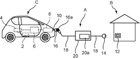
- FIG. 1 is an entire configuration diagram of a charging system to which a charging cable A for an electric propulsion vehicle according to a first embodiment of the present invention is applied.
- this charging system power is supplied to the electric propulsion vehicle C from a commercial power supply of a general household B via the charging cable A, and the battery 6 of the electric propulsion vehicle C is charged.
- the electric propulsion vehicle C includes a traveling motor 2, an inverter 4, a battery 6, and a charge control device 8.
- the traveling motor 2 to the charge control device 8 are electrically connected to each other.
- the electrically propelled vehicle C is connected to the charging cable A via the connector 10 connected to the charge control device 8.
- the traveling motor 2 is a motor that causes the electric propulsion vehicle C to travel.
- the inverter 4 converts the direct current power stored in the battery 6 into alternating current and supplies the alternating current to the traveling motor 2.
- the battery 6 is formed of, for example, a secondary battery such as a nickel hydrogen battery or a lithium ion battery, and is charged by a commercial power supply to store power.
- the charge control device 8 converts, for example, AC power supplied from a commercial power supply into DC power, and supplies the DC power to the battery 6.
- the charge control device 8 is formed of, for example, a switching regulator, and is supplied with a pilot signal from the control unit 20a, and supplies to the battery 6 a conduction current having a current value corresponding to the pilot signal.
- the charging cable A electrically connects the power outlet 12 provided on the outer wall of the house to the electric propulsion vehicle C side, and charges the battery 6 mounted on the electric propulsion vehicle C.
- the power outlet 12 is, for example, a commercial power outlet that has a waterproof structure that prevents a short circuit of the electrode due to rain water or the like, and supplies a single-phase two-wire AC 100 V.
- the charging cable A includes a power plug 14, a charging plug 16, and a charging device 20.
- the power plug 14 is detachably connected to the power outlet 12.
- the charging plug 16 is detachably connected to the connector 10 of the electric propulsion vehicle C.
- the power plug 14 and the charging plug 16 are electrically connected by the connection cable 18.
- the charging device 20 is provided in the middle of the connection cable 18 and includes a control unit 20a.
- the control unit 20a is configured of, for example, a microcomputer (micro controller).
- the power plug 14 includes a temperature detection unit 14 a that detects the temperature of the power plug 14 therein.
- the temperature detection unit 14 a is formed of, for example, a temperature sensor such as a thermistor, and is embedded in the power plug 14. A temperature signal indicating the detected temperature detected by the temperature detection unit 14a is input to the control unit 20a.
- the charging device 20 further includes a switching circuit and a leakage detection unit.
- the switching circuit is formed of, for example, a relay, and opens and closes an electric path between the power plug 14 and the charging plug 16.
- the leakage detection unit monitors the current flowing through the electric path to detect the leakage.
- the control unit 20a causes the switching circuit to cut off the electric path when the leakage detection unit detects the leakage. Thereby, the power supply from the commercial power source to the electric propulsion vehicle C is stopped.
- FIG. 2 is a block diagram of a charging cable A according to Embodiment 1 of the present invention.
- the temperature detection unit 14 a detects the temperature of the power plug 14 and outputs a temperature signal to the control unit 20 a.
- the control unit 20a stops energization to the battery 6, and the specified temperature is lower than the specified temperature T1.
- T1 first specified temperature
- T2 second specified temperature
- the specified temperature T1 a temperature slightly lower than the heat resistance temperature of the power plug 14 is adopted. For example, assuming that the heat resistance temperature is 65 degrees, a value of about 50 degrees is adopted. Further, as the specified temperature T2, for example, a temperature that does not damage the power plug 14 even if charging is resumed is adopted.
- the control unit 20a transmits a pilot signal for setting the conduction current to the battery 6 to the charge control device 8, and causes the charge control device 8 to supply the conduction current having a value according to the pilot signal to the battery 6.
- the electric power charged in the battery 6 is supplied to the traveling motor 2 via the inverter 4 and the traveling of the electric propulsion vehicle C becomes possible.
- the charge control device 8 determines the conduction current according to the duty ratio of the pulse wave.
- a pilot signal compliant with the SAE J1772 (SAE: American Association of Automotive Engineers) standard is used.
- SAE J1772 SAE: American Association of Automotive Engineers
- the relationship between the pilot signal and the duty ratio is, for example, the following relationship.
- control unit 20a adjusts the duty ratio of the pilot signal to determine the current value of the conduction current.
- this is an example and another method may be used.
- the control unit 20a may change the current value of the charging current by changing the pulse amplitude of the pilot signal.
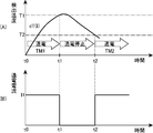
- FIG. 4 is a waveform diagram showing a control sequence of charging cable A in accordance with the first exemplary embodiment of the present invention, in which (A) shows temporal transition of detected temperature and (B) shows temporal transition of energizing current. .
- the vertical axis represents the detected temperature
- the horizontal axis represents time.
- the vertical axis indicates the current flow
- the horizontal axis indicates the time.
- the control unit 20a transmits, to the charge control device 8, a pilot signal for setting the conduction current to the current value I1.
- the current having the current value I1 is supplied to the battery 6, and the current supply is started.
- the control unit 20a turns off the switching circuit to stop the energization. As a result, the current flow becomes zero and the detected temperature gradually decreases.
- the detected temperature becomes equal to or lower than the specified temperature T2, so that the control unit 20a charges the pilot signal having the duty ratio for setting the energizing current to the current value I1 in order to restore energization to the battery 6. Send to As a result, the current flow is restored, and the current having the current value I1 is supplied to the battery 6 again.
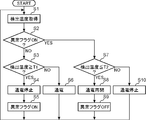
- FIG. 3 is a flowchart showing the operation of the charging cable A according to the first embodiment of the present invention.
- the control unit 20a is notified of the temperature signal from the temperature detection unit 14a, and acquires the detected temperature of the power plug 14 (S1).
- the control unit 20a acquires the detected temperature of the power plug 14 at a predetermined detection cycle.
- control unit 20a determines whether the abnormality flag is turned on (S2).
- the control unit 20a sets the abnormality flag to ON, and sets the anomaly flag to OFF during the energization.
- the control unit 20a determines whether the detected temperature is equal to or higher than the specified temperature T1 (S3). When the detected temperature is equal to or higher than the specified temperature T1 (Y in S3), the control unit 20a turns off the open / close circuit to stop the energization (S4). Next, the control unit 20a sets the abnormality flag to ON (S5), and returns the process to S1.
- control unit 20a continues the energization of the battery 6 (S6), and returns the process to S1.
- the control unit 20a determines whether the detected temperature is less than or equal to the specified temperature T2 (S7). Then, when the detected temperature is less than or equal to the specified temperature T2 (Y in S7), the control unit 20a turns on the open / close circuit and resumes energization to the battery 6 (S8). Next, the control unit 20a sets the abnormality flag to OFF (S9), and returns the process to S1. On the other hand, when the detected temperature is higher than the specified temperature T2 (N in S7), the control unit 20a maintains the current supply stop (S10).
- the detected temperature becomes higher than the specified temperature T1 and the energization is stopped, the detected temperature gradually decreases, and if the detected temperature is reduced to such a temperature that the power plug 14 is not damaged even if the energization is restarted. There is no problem even if the power supply is resumed.
- the temperature of the power plug 14 is monitored, and energization is stopped when the temperature becomes equal to or higher than the specified temperature T1, but monitoring of the temperature of the power plug 14 is continued thereafter and the power plug 14
- the energization is restarted.
- the charging cable A is connected to the electric propulsion vehicle C, such processing is repeated. Therefore, when the detected temperature exceeds a certain temperature, it is possible to secure a long conduction period as compared with the case of adopting the conventional configuration in which charging is discontinued.
- the detected temperature becomes higher than the specified temperature T1 because the temperature of the air by chance during the charging period is high. In some cases. In this case, even if the power supply is resumed, the number of times the detected temperature becomes equal to or higher than the specified temperature T1 may be reduced or zero if the temperature of the atmosphere is lowered. In such a case, the charging cable A is useful.
- the commercial power source is 100 V AC in the above embodiment, other AC voltages (for example, 200 V AC) can also be used. This applies to the following embodiments as well.
- Second Embodiment Charging cable A according to the second embodiment does not restore power to battery 6 even if the detected temperature falls below specified temperature T2 when the temperature gradient of the detected temperature in the current application period is equal to or higher than the predetermined specified temperature gradient. It is characterized by In the present embodiment, the same components as those of the first embodiment are denoted by the same reference numerals, and the description thereof is omitted.
- control unit 20a calculates the temperature gradient in power supply period TM1.
- the control unit 20a obtains the difference between the currently transmitted detected temperature and the previously transmitted detected temperature, and the difference is used as the detected temperature.
- the differential value of the detected temperature is obtained by dividing by the detection cycle, and stored in a memory (not shown).
- the control unit 20a temporarily ends the process of calculating the differential value of the detected temperature.
- the control unit 20a is a representative value of the differential values of the detected temperature of the energizing period TM1 stored in the memory. (For example, a median or an average value) is determined, and this representative value is determined as the temperature gradient dT (1) of the energization period TM1.
- the switch circuit is maintained in the OFF state, and the power to the battery 6 is not restored.
- the prescribed temperature gradient for example, a value may be employed which is assumed to be a steep temperature gradient of the detected temperature and in which the power plug 14 is clearly abnormal.
- an abnormality of the power supply plug 14 it may be mentioned that a rare short has occurred due to breakage of a component such as a blade.
- the second embodiment may be applied to any of the following embodiments.
- the charging cable A according to the third embodiment is characterized in that when the power supply to the battery 6 is restored, the power supply current is reduced compared to before the power supply stop.
- the same components as those in Embodiments 1 and 2 are denoted by the same reference numerals and the description thereof will be omitted.
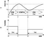
- FIG. 5 is a waveform diagram showing a control sequence of charging cable A in accordance with the third exemplary embodiment of the present invention, in which (A) shows temporal transition of detected temperature and (B) shows temporal transition of electrification current. .
- the vertical axis represents the detected temperature
- the horizontal axis represents time
- the vertical axis indicates the current flow
- the horizontal axis indicates the time.
- energization is stopped when the detected temperature becomes equal to or higher than the specified temperature T1, and is resumed when the detected temperature becomes equal to or lower than the specified temperature T2.
- the control unit 20a sets the pilot signal to set the energization current to the current value I2 ( ⁇ I1).
- the battery 6 is transmitted to the charge control device 8 and is energized by the energizing current of the current value I2.
- the current value I2 a current value lower than the current value I1 by a predetermined value can be employed.
- the temperature rise of the power supply plug 14 can be suppressed by lowering the current value of the conduction current at the time of restoration of the conduction, and the conduction period can be secured as much as possible.
- the charging of the battery 6 may be terminated to ensure safety. This is based on the idea that the detected temperature exceeds the specified temperature T2 despite the reduction of the current value, that the damage of the power plug 14 is serious.
- the conductive period TM2 in the case where the detected temperature becomes equal to or higher than the specified temperature T1 again in the conductive period TM2 and the current is terminated after the detected temperature becomes equal to or lower than the specified temperature T2, the conductive period The current may be supplied with the same current value I2 as TM2. In this case, in the subsequent energization periods TM4, TM5,..., TMn, energization may be performed with the energization current of the current value I2. In this way, although there is a possibility that the detected temperature becomes equal to the specified temperature T1, charging can be continued as much as possible.
- Embodiment 4 The charging cable A according to the fourth embodiment is characterized in that the energizing current is reduced each time the energization of the battery 6 is restored.
- the same components as those in Embodiments 1 to 3 are assigned the same reference numerals and explanation thereof is omitted.
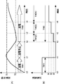
- FIG. 6 is a waveform diagram showing a control sequence of charging cable A in the fourth embodiment of the present invention, in which (A) shows a temporal transition of detected temperature and (B) shows a temporal transition of energizing current. .
- the vertical axis represents the detected temperature
- the horizontal axis represents time.
- the vertical axis indicates the current flow
- the horizontal axis indicates the time.
- the control unit 20a set the reduction width of the energization current smaller than the previous energization period as the previous energization period becomes longer. By doing this, it is possible to prevent the situation in which the time required to fully charge the battery 6 is unnecessarily reduced due to unnecessary reduction of the current flow. That is, the fact that the previous energizing period is long indicates that the temperature gradient of the detected temperature is small, and if the energizing current is lowered at the default reduction width in the next energizing period, the temperature gradient of the detected temperature is further reduced. As a result, the battery 6 can not be fully charged quickly. Therefore, in the present embodiment, the reduction width of the supplied current is made smaller as the previous conductive period becomes longer.
- the control unit 20a detects the length of the energization period TM2.
- the control unit 20a starts the count operation when the energization period TM2 starts, and stops the count operation when the energization period TM2 ends, thereby detecting the length of the energization period TM2, and detecting the length. Should be stored in memory.
- the control unit 20a compares the reference energization period TM_ref serving as a predetermined reference with the energization period TM2. If TM2 ⁇ TM_ref, the default reduction width ⁇ I_ref is corrected so that the default reduction width ⁇ I_ref of the conduction current is reduced, and the actual reduction width ⁇ I is calculated.
- the control unit 20a corrects the default reduction width ⁇ I_ref so that the default reduction width ⁇ I_ref of the energization current increases, and calculates the actual reduction width ⁇ I.
- TM_ref for example, a standard energization period required for the detected temperature to exceed the specified temperature T1 may be adopted.
- the reduction width ⁇ I may be calculated using a plurality of past energization periods.
- the average reduction width ⁇ _ref of the default may be corrected to calculate the actual reduction width ⁇ I by obtaining the average value of TM1 and TM2 and comparing this average value with the reference energization period TM_ref.
- FIG. 7 is a flowchart showing an operation of charging cable A in the fourth embodiment of the present invention.
- the difference from the flowchart shown in FIG. 3 is that S25 and S29 are added.
- the other processes of S21 to S24, S26 to S28, and S30 to S32 are the same as S1 to S10 of FIG.
- control unit 20a detects the length of the energization period and stores it in the memory.
- determination processing of the supplied current is executed from the past supplied period (S29), and the supplied current is resumed (S30).
- the process of determining the current flow has been described above.
- the lowering width may be a fixed value.
- the control unit 20a may lower the conduction current stepwise with the default reduction width ⁇ I_ref each time the conduction period arrives.
- control unit 20a may set the reduction width so that the reduction width ⁇ I becomes gradually smaller according to a predetermined pattern, and may lower the conduction current stepwise. In these cases, the control can be simplified.
- the charging cable A of the fifth embodiment restores the energization of the battery 6, the electrification current is decreased compared to that before the electrification stopping, and the electrification current is increased stepwise until the detected temperature becomes equal to or higher than the specified temperature T1. It is characterized by
- FIG. 8 is a waveform diagram showing a control sequence of charging cable A in the fifth embodiment of the present invention, in which (A) shows a temporal transition of detected temperature, and (B) shows a temporal transition of energizing current. .
- the vertical axis represents the detected temperature
- the horizontal axis represents time.
- the vertical axis indicates the current flow
- the horizontal axis indicates the time.
- the control sequence is the same as in the first to fourth embodiments, in which the current flow is stopped when the detected temperature exceeds the specified temperature T1 and is returned when the detected temperature becomes less than the specified temperature T2. It is.
- the current value I2 is made much lower than the current value I1, and thereafter, while monitoring the detected temperature, the current value of the energization current is gradually increased to I3 and I4. I will let you.
- the control unit 20a monitors the detected temperature in the determination period TM (I2) after resuming the energization at the time t2, and determines the determination period TM (time t3) which is the end time of the determination period TM (I2). If the increase value of the detected temperature of I2) is equal to or less than the reference increase value ⁇ T_ref (I2), the current value is increased from I2 to I3.
- the determination period TM (I2) a period predetermined according to the current value I2 is employed. Also, values corresponding to the current values I3, I4,... Are adopted for the determination periods TM (I3), TM (I4),.
- ⁇ T_ref (I2) an increase value of a standard detected temperature when energization is performed at the current value I2 or an increase value slightly higher than the increase value thereof is adopted.
- the control unit 20a monitors the detected temperature in the determination period TM (I3), and determines the determination period at time t4 when the determination period TM (I3) ends. If the rise value of the detected temperature in TM (I3) is equal to or less than the reference rise value ⁇ T_ref (I3), the current value is increased from I3 to I4. On the other hand, at time t3, if the rise value of the detected temperature is larger than the reference rise value ⁇ T_ref (I3), the control unit 20a does not increase the current value and maintains it at I3.
- the increase value of the detected temperature is equal to or less than the reference increase value ⁇ T_ref (I3), so the current value is increased from I3 to I4.
- the detected temperature is monitored, and at the end of the determination period TM (I (i)), the increase value of the detected temperature in the determination period TM (I (i)) becomes the reference increase value ⁇ T_ref (I (i))
- the current value is increased from I (i) to I (i + 1).
- the determination periods TM (I2), TM (I3), and TM (I4) gradually increase, but this is only an example, and may be gradually decreased. It may be fixed.
- the point of stopping the current flow is the same as the first to fourth embodiments. Then, when the detected temperature T1 becomes equal to or higher than the specified temperature T1 again, after decreasing the current value significantly as compared to the previous time shown in FIG. 8B, control to gradually increase the supplied current while monitoring the detected temperature.
- a sequence may be adopted.
- the present invention is not limited thereto.
- the temperature gradient of the detected temperature May be compared to a reference temperature gradient to determine whether to increase the current value.
- the control unit 20a calculates a differential value of the detected temperature by dividing the difference between the currently acquired detected temperature and the previously acquired detected temperature by the detection cycle each time the detected temperature is acquired in the determination period TM (I2). Accumulate in Then, when time t3 that is the end time of the determination period TM (I2) arrives, the control unit 20a displays the representative value (for example, median value or average value) of the differential values of the detection temperature of the determination period TM (I2) accumulated in the memory ) Is calculated as the temperature gradient dT (I2) in the determination period TM (I2).
- the representative value for example, median value or average value
- control unit 20a may increase the current value from I2 to I3 if the temperature gradient dT (I2) is equal to or less than a predetermined reference temperature gradient dT_ref (I2) with respect to the current value I2.
- a predetermined reference temperature gradient dT_ref (I2) a temperature gradient slightly larger than a standard temperature gradient when the current value I2 is applied or the temperature gradient may be employed.
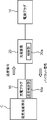
- FIG. 9 is an entire configuration diagram of a charging system to which charging cable A in a sixth embodiment of the present invention is applied.
- FIG. 10 is a block diagram of a charging cable A according to mode 6 of the present invention.
- FIG. 9 it turns out that the temperature detection part 16a is arrange
- FIG. 10 When the connection between the charging plug 16 and the connector 10 of the electric propulsion vehicle C is incomplete, abnormal heating may occur in the charging plug 16. In addition, if the charging plug 16 and the connector 10 are connected for a long time, dust may accumulate between the charging plug 16 and the connector 10 to cause a tracking phenomenon, and abnormal heating may occur in the charging plug 16.
- the temperature detection unit 16 a is disposed in the charging plug 16. Therefore, abnormal heat generation occurring in the charging plug 16 can be accurately detected. Then, even if the temperature of the charging plug 16 becomes equal to or higher than the specified temperature T1 and the energization is stopped, when the temperature of the charging plug 16 falls to the specified temperature T2 or less, the energization is performed similarly to the first to fifth embodiments. It is returned. Therefore, even if some abnormal heat generation occurs in the charging plug 16, the energization time can be secured to fully charge the battery.
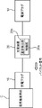
- FIG. 11 is a block diagram of charge cable A in the seventh embodiment of the present invention. As shown in FIG. 11, the temperature detection unit 20b is disposed in the control unit 20a.
- the temperature detection unit 20b is disposed in the control unit 20a. Therefore, abnormal heat generation occurring in the control unit 20a can be accurately detected. Then, even if the temperature of the control unit 20a becomes equal to or higher than the specified temperature T1 and the energization is stopped, when the temperature of the control unit 20a decreases to the specified temperature T2 or less, the energization is performed similarly to the first to fifth embodiments. It is returned. Therefore, even if some abnormal heat generation occurs in the control unit 20a, the energization time can be secured to fully charge the battery.
- a charging cable according to the present invention is a charging cable for an electric propulsion vehicle that charges a battery of the electric propulsion vehicle, and a power plug detachably connected to a power outlet of a commercial power source, and the electric propulsion vehicle It has a charging plug that is detachably connected, a temperature detection unit that detects the ambient temperature, and a control unit that generates a pilot signal for adjusting the current supplied to the battery and transmits the pilot signal to the electric propulsion vehicle.
- the control unit stops energization of the battery when the detected temperature detected by the temperature detection unit is equal to or higher than a predetermined first specified temperature, and the second detected temperature is lower than the first specified temperature. When the temperature drops below the specified temperature, the power supply to the battery is restored.
- the ambient temperature is monitored by the temperature detection unit, and the current supply is stopped when the ambient temperature exceeds the first specified temperature, but the ambient temperature monitoring is continued thereafter and the ambient temperature is When the temperature falls below the second specified temperature, energization is resumed. And, while the charging cable is connected to the electric propulsion vehicle, such processing is repeated. Therefore, when the detected temperature exceeds a certain temperature, the battery can be fully charged by securing the energization period as compared with the case of adopting the conventional configuration in which the charging is discontinued.
- the control unit preferably generates a pilot signal that reduces the current flow compared to before the current flow is stopped when the current flow to the battery is restored.
- control unit generates a pilot signal that reduces the supplied current more than the previous supplied period each time the supply of electricity to the battery is restored.
- control unit sets the reduction width of the energization current smaller than the previous energization period as the past one or more energization periods become longer.
- control unit restores the energization of the battery
- the control unit reduces the energization current compared to the previous energization period, and steps the energization current until the detected temperature becomes equal to or higher than the first specified temperature. It is preferable to generate a pilot signal that is incrementally increased.
- the conduction current is gradually increased until the detected temperature becomes equal to or higher than the first specified temperature, so that the battery can be charged with an appropriate current value.
- the control unit energizes the battery even if the detected temperature falls below the second prescribed temperature. It is preferable not to return.
- the said temperature detection part is provided in the said control part.
- abnormal heat generation of the control unit can be accurately detected.
- the battery can be fully charged by securing the energization period.
- the said temperature detection part is provided in the said power supply plug.
- abnormal heat generation of the power plug can be accurately detected.
- the battery can be fully charged by securing the energization period.
- the said temperature detection part is provided in the said charging plug.
- abnormal heat generation of the charging plug can be accurately detected.
- the battery can be fully charged by securing the energization period.
- the safety can be secured, and the current-carrying period can be secured as much as possible, so it is useful as a charging cable for a household charging facility for charging an electric propulsion vehicle.
Landscapes
- Engineering & Computer Science (AREA)
- Power Engineering (AREA)
- Transportation (AREA)
- Mechanical Engineering (AREA)
- Life Sciences & Earth Sciences (AREA)
- Sustainable Development (AREA)
- Sustainable Energy (AREA)
- Chemical & Material Sciences (AREA)
- Manufacturing & Machinery (AREA)
- Chemical Kinetics & Catalysis (AREA)
- Electrochemistry (AREA)
- General Chemical & Material Sciences (AREA)
- Electric Propulsion And Braking For Vehicles (AREA)
- Charge And Discharge Circuits For Batteries Or The Like (AREA)
- Insulated Conductors (AREA)
- Secondary Cells (AREA)
Abstract
Priority Applications (4)
| Application Number | Priority Date | Filing Date | Title |
|---|---|---|---|
| EP13758710.1A EP2824794B1 (fr) | 2012-03-08 | 2013-03-08 | Câble de charge |
| CN201380013242.8A CN104205554B (zh) | 2012-03-08 | 2013-03-08 | 充电线缆 |
| US14/383,280 US9515498B2 (en) | 2012-03-08 | 2013-03-08 | Charging cable |
| JP2014503506A JP5867587B2 (ja) | 2012-03-08 | 2013-03-08 | 充電ケーブル |
Applications Claiming Priority (2)
| Application Number | Priority Date | Filing Date | Title |
|---|---|---|---|
| JP2012051911 | 2012-03-08 | ||
| JP2012-051911 | 2012-03-08 |
Publications (1)
| Publication Number | Publication Date |
|---|---|
| WO2013132874A1 true WO2013132874A1 (fr) | 2013-09-12 |
Family
ID=49116363
Family Applications (1)
| Application Number | Title | Priority Date | Filing Date |
|---|---|---|---|
| PCT/JP2013/001541 WO2013132874A1 (fr) | 2012-03-08 | 2013-03-08 | Câble de charge |
Country Status (5)
| Country | Link |
|---|---|
| US (1) | US9515498B2 (fr) |
| EP (1) | EP2824794B1 (fr) |
| JP (1) | JP5867587B2 (fr) |
| CN (1) | CN104205554B (fr) |
| WO (1) | WO2013132874A1 (fr) |
Cited By (11)
| Publication number | Priority date | Publication date | Assignee | Title |
|---|---|---|---|---|
| CN104464942A (zh) * | 2014-12-05 | 2015-03-25 | 东南(福建)汽车工业有限公司 | 一种温度可监测的高压线束 |
| FR3011688A1 (fr) * | 2013-10-08 | 2015-04-10 | Renault Sa | Prise electrique securisee en temperature |
| EP3000647A3 (fr) * | 2014-09-01 | 2016-04-06 | LSIS Co., Ltd. | Dispositif et procédé de chargement de véhicule |
| JP2016197981A (ja) * | 2015-04-06 | 2016-11-24 | 株式会社Nttファシリティーズ | 遮断器制御システム、電源制御システム、遮断器制御方法、及びプログラム |
| JP2017011798A (ja) * | 2015-06-17 | 2017-01-12 | 株式会社椿本チエイン | 電力変換装置、コンピュータプログラム及び電力変換方法 |
| CN106415945A (zh) * | 2014-06-13 | 2017-02-15 | 索尼公司 | 电缆和电源供应设备 |
| KR101769466B1 (ko) * | 2014-05-19 | 2017-08-18 | 주식회사 파워큐브코리아 | 온도에 따라 충전을 제어하는 전기자동차 충전 및 과금시스템 |
| JP2018500724A (ja) * | 2014-11-13 | 2018-01-11 | アウディ アクチェンゲゼルシャフトAudi Ag | 過熱保護機能を有する原動機付き車両の充電ソケット |
| JP2019140827A (ja) * | 2018-02-13 | 2019-08-22 | トヨタ自動車株式会社 | 車両の電力制御装置 |
| WO2022035688A1 (fr) * | 2020-08-10 | 2022-02-17 | Webasto Charging Systems, Inc. | Procédé et système de régulation de température pour un chargeur portable |
| JP7454445B2 (ja) | 2020-05-11 | 2024-03-22 | 新電元工業株式会社 | 電気自動車用充電装置 |
Families Citing this family (26)
| Publication number | Priority date | Publication date | Assignee | Title |
|---|---|---|---|---|
| DE102014201764A1 (de) * | 2014-01-31 | 2015-08-06 | Siemens Aktiengesellschaft | Elektrische Verbindungsvorrichtung und Ladekabel für ein Elektrofahrzeug |
| KR101587357B1 (ko) * | 2014-09-01 | 2016-01-20 | 엘에스산전 주식회사 | 차량 충전 장치 및 충전 방법 |
| JP6176272B2 (ja) * | 2015-02-27 | 2017-08-09 | トヨタ自動車株式会社 | 電力伝送システム |
| CN104767180B (zh) * | 2015-03-20 | 2018-06-08 | 深圳市万普拉斯科技有限公司 | Usb接口大电流充电保护方法和系统 |
| CN107407704B (zh) * | 2015-03-23 | 2021-05-18 | 伟巴斯特充电系统公司 | 监测电源连接器及电缆健康的系统 |
| WO2017101047A1 (fr) * | 2015-12-16 | 2017-06-22 | 广东欧珀移动通信有限公司 | Procédé et dispositif de commande de charge, adaptateur d'alimentation, et terminal mobile |
| JP6294903B2 (ja) * | 2016-03-22 | 2018-03-14 | 株式会社Subaru | 車両 |
| US20170334300A1 (en) * | 2016-05-20 | 2017-11-23 | Faraday&Future Inc. | Charging System with Temperature Sensor |
| FR3051558B1 (fr) * | 2016-05-20 | 2018-05-25 | Peugeot Citroen Automobiles Sa | Dispositif d'analyse pour une prise electrique propre a etre connectee a une autre prise electrique |
| CN105914846B (zh) * | 2016-06-30 | 2018-05-29 | 洛阳嘉盛新能源科技有限公司 | 一种防拉弧及高温的保护装置 |
| CN205985683U (zh) * | 2016-09-08 | 2017-02-22 | 代中彦 | 一种电动车的充电延长线 |
| CN107054118A (zh) * | 2017-01-25 | 2017-08-18 | 上海蔚来汽车有限公司 | 电动汽车的充电装置、充电系统及充电方法 |
| DE102017102783A1 (de) | 2017-02-13 | 2018-08-16 | Dr. Ing. H.C. F. Porsche Aktiengesellschaft | Stromleitungselement und System zur Isolationsüberwachung |
| CN108808755A (zh) * | 2017-05-03 | 2018-11-13 | 江阴信邦电子有限公司 | 充电装置的过温保护系统 |
| CN207265713U (zh) * | 2017-07-28 | 2018-04-20 | 特斯拉公司 | 具有热保护的充电系统 |
| KR102441070B1 (ko) * | 2017-10-16 | 2022-09-06 | 현대자동차주식회사 | 충전용 인렛의 과온 방지 장치 및 그 방법 |
| CN110239378B (zh) * | 2019-07-04 | 2022-03-25 | 广州顺充新能源有限公司 | 一种交流充电桩自适应电流输出的控制方法 |
| CN110303920A (zh) * | 2019-07-31 | 2019-10-08 | 南京康尼新能源汽车零部件有限公司 | 交流充电连接装置及温度保护方法 |
| DE102019121108B3 (de) * | 2019-08-05 | 2020-09-24 | Juice Technology AG | Mobile Ladestation für ein Elektrofahrzeug |
| DE102019122377A1 (de) * | 2019-08-20 | 2021-02-25 | Bender Gmbh & Co. Kg | Verfahren und Schaltungsanordnung zur Not-Entriegelung eines Ladesteckers für eine Ladestation zur Aufladung eines elektrischen Energiespeichers eines Elektrofahrzeugs |
| CN112248866B (zh) * | 2020-11-06 | 2022-04-29 | 长春捷翼汽车零部件有限公司 | 一种电动车辆充电控制装置及方法 |
| DE102021113254B3 (de) | 2021-05-21 | 2022-08-11 | Juice Technology AG | Mobile Ladevorrichtung |
| NO347592B1 (en) * | 2021-06-16 | 2024-01-22 | Defa As | A charging assembly and method |
| CN113459839B (zh) * | 2021-07-23 | 2023-04-25 | 吉林省中赢高科技有限公司 | 基于直流充电座温度补偿的方法及装置 |
| DE102022004329A1 (de) | 2021-12-06 | 2023-06-07 | Mercedes-Benz Group AG | System zum Schutz von Ladekupplungen gegen Übertemperatur und Verfahren dazu |
| DE102021006497A1 (de) | 2021-12-31 | 2023-07-06 | Voitas Innovations GmbH | Ladevorrichtung zum Laden von elektrischen Energiespeichern |
Citations (3)
| Publication number | Priority date | Publication date | Assignee | Title |
|---|---|---|---|---|
| JP2008252986A (ja) * | 2007-03-29 | 2008-10-16 | Toyota Motor Corp | 充電ケーブルおよび充電システム |
| JP2010110055A (ja) | 2008-10-28 | 2010-05-13 | Panasonic Electric Works Co Ltd | 電気自動車用充電ケーブル |
| JP2011205758A (ja) * | 2010-03-25 | 2011-10-13 | Fuji Heavy Ind Ltd | 充電装置 |
Family Cites Families (15)
| Publication number | Priority date | Publication date | Assignee | Title |
|---|---|---|---|---|
| JP2541811Y2 (ja) | 1987-12-18 | 1997-07-23 | 株式会社 畑屋製作所 | コード巻取り装置 |
| US7576525B2 (en) * | 2006-10-21 | 2009-08-18 | Advanced Analogic Technologies, Inc. | Supply power control with soft start |
| JP4254890B2 (ja) * | 2007-09-20 | 2009-04-15 | トヨタ自動車株式会社 | 車両の制御装置 |
| US20090167537A1 (en) | 2007-12-28 | 2009-07-02 | Feliss Norbert A | Minimizing electrical outlet safety failures due to over temperature condition |
| JP2010052861A (ja) | 2008-08-26 | 2010-03-11 | Panasonic Electric Works Co Ltd | 電気自動車充電用コードセット |
| CN102132468B (zh) * | 2008-08-26 | 2015-06-24 | 松下电器产业株式会社 | 电动车充电线组 |
| CN102196942B (zh) * | 2008-10-28 | 2014-11-12 | 松下电器产业株式会社 | 用于电动车的充电电缆、充电电缆单元以及充电系统 |
| JP5289114B2 (ja) * | 2009-03-11 | 2013-09-11 | オムロンオートモーティブエレクトロニクス株式会社 | 電源制御装置および方法 |
| DE102009034886A1 (de) * | 2009-07-27 | 2011-02-03 | Rwe Ag | Ladekabelstecker zur Verbindung eines Elektrofahrzeuges mit einer Ladestation |
| WO2011064856A1 (fr) * | 2009-11-26 | 2011-06-03 | トヨタ自動車株式会社 | Dispositif de chargement |
| WO2011127446A2 (fr) * | 2010-04-09 | 2011-10-13 | Aerovironment, Inc. | Câble de charge portatif doté d'un organe de commande en ligne |
| CN201927858U (zh) * | 2011-01-07 | 2011-08-10 | 上海海事大学 | 温差式智能防火插座 |
| US9308825B2 (en) * | 2011-01-19 | 2016-04-12 | Aerovironment, Inc. | Electric vehicle docking connector with embedded EVSE controller |
| JP5934905B2 (ja) * | 2011-03-03 | 2016-06-15 | パナソニックIpマネジメント株式会社 | 電気推進車両用充電ケーブル |
| GB2489988B (en) * | 2011-04-15 | 2014-06-25 | Nissan Motor Mfg Uk Ltd | Improvements in electrical connections |
-
2013
- 2013-03-08 CN CN201380013242.8A patent/CN104205554B/zh active Active
- 2013-03-08 JP JP2014503506A patent/JP5867587B2/ja active Active
- 2013-03-08 US US14/383,280 patent/US9515498B2/en active Active
- 2013-03-08 WO PCT/JP2013/001541 patent/WO2013132874A1/fr active Application Filing
- 2013-03-08 EP EP13758710.1A patent/EP2824794B1/fr active Active
Patent Citations (3)
| Publication number | Priority date | Publication date | Assignee | Title |
|---|---|---|---|---|
| JP2008252986A (ja) * | 2007-03-29 | 2008-10-16 | Toyota Motor Corp | 充電ケーブルおよび充電システム |
| JP2010110055A (ja) | 2008-10-28 | 2010-05-13 | Panasonic Electric Works Co Ltd | 電気自動車用充電ケーブル |
| JP2011205758A (ja) * | 2010-03-25 | 2011-10-13 | Fuji Heavy Ind Ltd | 充電装置 |
Non-Patent Citations (1)
| Title |
|---|
| See also references of EP2824794A4 |
Cited By (14)
| Publication number | Priority date | Publication date | Assignee | Title |
|---|---|---|---|---|
| FR3011688A1 (fr) * | 2013-10-08 | 2015-04-10 | Renault Sa | Prise electrique securisee en temperature |
| KR101769466B1 (ko) * | 2014-05-19 | 2017-08-18 | 주식회사 파워큐브코리아 | 온도에 따라 충전을 제어하는 전기자동차 충전 및 과금시스템 |
| CN106415945A (zh) * | 2014-06-13 | 2017-02-15 | 索尼公司 | 电缆和电源供应设备 |
| EP3000647A3 (fr) * | 2014-09-01 | 2016-04-06 | LSIS Co., Ltd. | Dispositif et procédé de chargement de véhicule |
| JP2018500724A (ja) * | 2014-11-13 | 2018-01-11 | アウディ アクチェンゲゼルシャフトAudi Ag | 過熱保護機能を有する原動機付き車両の充電ソケット |
| US10286791B2 (en) | 2014-11-13 | 2019-05-14 | Audi Ag | Motor vehicle charging socket having overheating protection |
| CN104464942A (zh) * | 2014-12-05 | 2015-03-25 | 东南(福建)汽车工业有限公司 | 一种温度可监测的高压线束 |
| JP2016197981A (ja) * | 2015-04-06 | 2016-11-24 | 株式会社Nttファシリティーズ | 遮断器制御システム、電源制御システム、遮断器制御方法、及びプログラム |
| JP2017011798A (ja) * | 2015-06-17 | 2017-01-12 | 株式会社椿本チエイン | 電力変換装置、コンピュータプログラム及び電力変換方法 |
| JP2019140827A (ja) * | 2018-02-13 | 2019-08-22 | トヨタ自動車株式会社 | 車両の電力制御装置 |
| JP6992567B2 (ja) | 2018-02-13 | 2022-01-13 | トヨタ自動車株式会社 | 車両の電力制御装置 |
| JP7454445B2 (ja) | 2020-05-11 | 2024-03-22 | 新電元工業株式会社 | 電気自動車用充電装置 |
| WO2022035688A1 (fr) * | 2020-08-10 | 2022-02-17 | Webasto Charging Systems, Inc. | Procédé et système de régulation de température pour un chargeur portable |
| US11472301B2 (en) | 2020-08-10 | 2022-10-18 | Webasto Charging Systems, Inc. | Method and system for temperature regulation for a portable charger |
Also Published As
| Publication number | Publication date |
|---|---|
| JPWO2013132874A1 (ja) | 2015-07-30 |
| EP2824794A1 (fr) | 2015-01-14 |
| EP2824794A4 (fr) | 2016-02-24 |
| US9515498B2 (en) | 2016-12-06 |
| EP2824794B1 (fr) | 2018-01-03 |
| CN104205554A (zh) | 2014-12-10 |
| US20150028809A1 (en) | 2015-01-29 |
| JP5867587B2 (ja) | 2016-02-24 |
| CN104205554B (zh) | 2017-09-01 |
Similar Documents
| Publication | Publication Date | Title |
|---|---|---|
| WO2013132874A1 (fr) | Câble de charge | |
| JP5934905B2 (ja) | 電気推進車両用充電ケーブル | |
| US10439417B2 (en) | Battery temperature management and charging system | |
| US9929674B2 (en) | Power supply system for vehicle | |
| JP5854242B2 (ja) | 電動車両を用いた電力供給装置 | |
| CN109038772B (zh) | 充电控制装置 | |
| JP6670998B2 (ja) | 電力変換装置 | |
| JP2019140775A (ja) | 車載充電装置、及び車載充電装置の制御方法 | |
| KR101664745B1 (ko) | 배터리의 릴레이 융착 검출 방법 | |
| JP2009290978A (ja) | 車両用電源回路の故障検出方法及びその装置 | |
| KR101470254B1 (ko) | 친환경 자동차의 급속충전 릴레이 융착 검출 방법 | |
| JP2014003737A (ja) | 充電制御装置 | |
| JP2013198372A (ja) | 電気自動車の充電制御装置 | |
| JP5108076B2 (ja) | 車両充電装置 | |
| WO2018179855A1 (fr) | Dispositif de commande de batterie | |
| EP3564981B1 (fr) | Dispositif de relais | |
| CN115848201A (zh) | 车辆及车辆的充电方法 | |
| JP7430978B2 (ja) | 電源システム及びその制御方法 | |
| JP5919517B2 (ja) | 車載用充電装置 | |
| JP2017017766A (ja) | 車両電池システム |
Legal Events
| Date | Code | Title | Description |
|---|---|---|---|
| 121 | Ep: the epo has been informed by wipo that ep was designated in this application |
Ref document number: 13758710 Country of ref document: EP Kind code of ref document: A1 |
|
| ENP | Entry into the national phase |
Ref document number: 2014503506 Country of ref document: JP Kind code of ref document: A |
|
| NENP | Non-entry into the national phase |
Ref country code: DE |
|
| WWE | Wipo information: entry into national phase |
Ref document number: 14383280 Country of ref document: US |
|
| WWE | Wipo information: entry into national phase |
Ref document number: 2013758710 Country of ref document: EP |