WO2013129571A1 - 電気化学素子電極用複合粒子、電気化学素子電極用複合粒子の製造方法、電気化学素子電極材料及び電気化学素子電極 - Google Patents
電気化学素子電極用複合粒子、電気化学素子電極用複合粒子の製造方法、電気化学素子電極材料及び電気化学素子電極 Download PDFInfo
- Publication number
- WO2013129571A1 WO2013129571A1 PCT/JP2013/055400 JP2013055400W WO2013129571A1 WO 2013129571 A1 WO2013129571 A1 WO 2013129571A1 JP 2013055400 W JP2013055400 W JP 2013055400W WO 2013129571 A1 WO2013129571 A1 WO 2013129571A1
- Authority
- WO
- WIPO (PCT)
- Prior art keywords
- electrochemical element
- element electrode
- particles
- external additive
- active material
- Prior art date
- Legal status (The legal status is an assumption and is not a legal conclusion. Google has not performed a legal analysis and makes no representation as to the accuracy of the status listed.)
- Ceased
Links
Classifications
-
- H—ELECTRICITY
- H01—ELECTRIC ELEMENTS
- H01M—PROCESSES OR MEANS, e.g. BATTERIES, FOR THE DIRECT CONVERSION OF CHEMICAL ENERGY INTO ELECTRICAL ENERGY
- H01M4/00—Electrodes
- H01M4/02—Electrodes composed of, or comprising, active material
- H01M4/36—Selection of substances as active materials, active masses, active liquids
- H01M4/58—Selection of substances as active materials, active masses, active liquids of inorganic compounds other than oxides or hydroxides, e.g. sulfides, selenides, tellurides, halogenides or LiCoFy; of polyanionic structures, e.g. phosphates, silicates or borates
- H01M4/583—Carbonaceous material, e.g. graphite-intercalation compounds or CFx
- H01M4/587—Carbonaceous material, e.g. graphite-intercalation compounds or CFx for inserting or intercalating light metals
-
- H—ELECTRICITY
- H01—ELECTRIC ELEMENTS
- H01M—PROCESSES OR MEANS, e.g. BATTERIES, FOR THE DIRECT CONVERSION OF CHEMICAL ENERGY INTO ELECTRICAL ENERGY
- H01M4/00—Electrodes
- H01M4/02—Electrodes composed of, or comprising, active material
- H01M4/13—Electrodes for accumulators with non-aqueous electrolyte, e.g. for lithium-accumulators; Processes of manufacture thereof
- H01M4/133—Electrodes based on carbonaceous material, e.g. graphite-intercalation compounds or CFx
-
- H—ELECTRICITY
- H01—ELECTRIC ELEMENTS
- H01M—PROCESSES OR MEANS, e.g. BATTERIES, FOR THE DIRECT CONVERSION OF CHEMICAL ENERGY INTO ELECTRICAL ENERGY
- H01M4/00—Electrodes
- H01M4/02—Electrodes composed of, or comprising, active material
- H01M4/13—Electrodes for accumulators with non-aqueous electrolyte, e.g. for lithium-accumulators; Processes of manufacture thereof
- H01M4/139—Processes of manufacture
- H01M4/1393—Processes of manufacture of electrodes based on carbonaceous material, e.g. graphite-intercalation compounds or CFx
-
- H—ELECTRICITY
- H01—ELECTRIC ELEMENTS
- H01M—PROCESSES OR MEANS, e.g. BATTERIES, FOR THE DIRECT CONVERSION OF CHEMICAL ENERGY INTO ELECTRICAL ENERGY
- H01M4/00—Electrodes
- H01M4/02—Electrodes composed of, or comprising, active material
- H01M4/36—Selection of substances as active materials, active masses, active liquids
- H01M4/362—Composites
- H01M4/366—Composites as layered products
-
- H—ELECTRICITY
- H01—ELECTRIC ELEMENTS
- H01M—PROCESSES OR MEANS, e.g. BATTERIES, FOR THE DIRECT CONVERSION OF CHEMICAL ENERGY INTO ELECTRICAL ENERGY
- H01M4/00—Electrodes
- H01M4/02—Electrodes composed of, or comprising, active material
- H01M4/62—Selection of inactive substances as ingredients for active masses, e.g. binders, fillers
- H01M4/621—Binders
- H01M4/622—Binders being polymers
-
- H—ELECTRICITY
- H01—ELECTRIC ELEMENTS
- H01M—PROCESSES OR MEANS, e.g. BATTERIES, FOR THE DIRECT CONVERSION OF CHEMICAL ENERGY INTO ELECTRICAL ENERGY
- H01M10/00—Secondary cells; Manufacture thereof
- H01M10/05—Accumulators with non-aqueous electrolyte
- H01M10/052—Li-accumulators
-
- Y—GENERAL TAGGING OF NEW TECHNOLOGICAL DEVELOPMENTS; GENERAL TAGGING OF CROSS-SECTIONAL TECHNOLOGIES SPANNING OVER SEVERAL SECTIONS OF THE IPC; TECHNICAL SUBJECTS COVERED BY FORMER USPC CROSS-REFERENCE ART COLLECTIONS [XRACs] AND DIGESTS
- Y02—TECHNOLOGIES OR APPLICATIONS FOR MITIGATION OR ADAPTATION AGAINST CLIMATE CHANGE
- Y02E—REDUCTION OF GREENHOUSE GAS [GHG] EMISSIONS, RELATED TO ENERGY GENERATION, TRANSMISSION OR DISTRIBUTION
- Y02E60/00—Enabling technologies; Technologies with a potential or indirect contribution to GHG emissions mitigation
- Y02E60/10—Energy storage using batteries
Definitions
- the present invention relates to a composite particle for an electrochemical element electrode having fluidity and excellent adhesion to a current collector, a method for producing a composite particle for an electrochemical element electrode, and an electrochemical element using the composite particle
- the present invention relates to an electrode material and an electrochemical element electrode.
- Lithium ion secondary batteries have a high energy density and are used in the fields of mobile phones and notebook personal computers.
- Electric double layer capacitors can be used for memory backup compact power supplies for personal computers and the like because they can be charged and discharged rapidly. ing.
- lithium ion capacitors that utilize the oxidation-reduction reaction (pseudo electric double layer capacity) on the surface of metal oxides or conductive polymers are also attracting attention because of their large capacity. With the expansion and development of applications, these electrochemical devices are required to have further improved performance such as low resistance and large capacity.
- Patent Document 1 since the viscosity modifier is not used, the viscosity of the slurry was low. Therefore, when the binder in the composite particles is localized on the surface, the fluidity of the composite particles is deteriorated, and it is difficult to produce an electrode having a uniform film thickness. Therefore, Patent Document 2 proposes a method of coating the surface of the composite particle with an external additive.
- Patent Document 3 a material for triboelectric charging is used as an external additive in order to increase the coating efficiency on the current collector.
- a method has been proposed in which the composite particles used are prepared to obtain an electrode for an electrochemical device.
- the composite particles used when producing the electrode for an electrochemical element have good fluidity and good adhesion to the current collector. Moreover, when it is set as an electrochemical element, it is calculated
- An object of the present invention is to provide a composite particle for an electrochemical element electrode having fluidity, good adhesion to a current collector, and low resistance when used as an electrochemical element, and a method for producing the composite particle for an electrochemical element electrode Furthermore, it aims at providing the electrochemical element electrode material and electrochemical element electrode which used this composite particle for electrochemical element electrodes.
- the inventor of the present invention has fluidity by coating composite particles with an external additive containing organic fine particles having a glass transition temperature (Tg) in a specific range, and a current collector. It was found that composite particles for electrochemical device electrodes having good adhesion and low resistance when formed into electrochemical devices can be obtained.
- Tg glass transition temperature
- a composite particle for an electrochemical element electrode comprising organic fine particles, (2) The composite particle for an electrochemical element electrode according to (1), wherein the coverage with the organic fine particles is 0.1 to 20%, (3) The composite particle for an electrochemical element electrode according to (1) or (2), wherein the external additive further includes a conductive external additive having a powder resistance of less than 100 ⁇ ⁇ cm, (4) The composite particle for an electrochemical element electrode according to (3), wherein the coverage covered with the conductive external additive is 0.01 to 2%, (5) The method for producing composite particles for electrochemical device electrodes according to any one of (1) to (4), wherein a slurry is obtained by dispersing a mixture containing at least a binder and a solvent (I) And a step (II) of spray-drying the slurry to obtain composite particles, and a step (III) of dry-mixing the composite particles and an external additive.
- an electrode activity is added to the mixture.
- a method for producing composite particles for an electrochemical element electrode further comprising a substance, or in the step (II), flowing an electrode active material in a heated air stream and spraying and drying the slurry therein; (6) An electrochemical element electrode material comprising the composite particle for an electrochemical element electrode according to any one of (1) to (4), (7) An electrochemical element electrode formed by laminating an active material layer formed from the electrochemical element electrode material according to (6) on a current collector, (8) The electrochemical element electrode according to (7), wherein the active material layer is laminated on the current collector by pressure molding, (9) The electrochemical element electrode according to (8), wherein the pressure molding is roll pressure molding, (10) The electrochemical element electrode according to (9), wherein a roll temperature in the roll press molding is higher by 10 ° C. or more and less than 50 ° C. than a glass transition temperature of the organic fine particles.
- ADVANTAGE OF THE INVENTION according to this invention, it has fluidity
- the electrochemical element electrode composite particle of the present invention (hereinafter sometimes referred to as the composite particle of the present invention) is an electrochemical element in which the surface of a composite particle containing an electrode active material and a binder is coated with an external additive.
- the external additive includes organic fine particles having a glass transition temperature (Tg) of 30 ° C. or higher and 80 ° C. or lower.
- the electrode active material used for this invention is suitably selected according to the kind of electrochemical element.
- “positive electrode active material” means an electrode active material for a positive electrode
- “negative electrode active material” means an electrode active material for a negative electrode
- the “positive electrode active material layer” means an electrode active material layer provided on the positive electrode
- the “negative electrode active material layer” means an electrode active material layer provided on the negative electrode.
- the positive electrode active material may be a compound containing a transition metal, specifically, an oxide containing a transition metal, or lithium and a transition metal. And a composite oxide can be used. Examples of such transition metals include cobalt, manganese, nickel, iron and the like.
- polymers such as polyacetylene, poly-p-phenylene, and polyquinone can be used.
- a compound containing nickel particularly a composite oxide containing lithium and nickel is preferably used.
- a composite oxide containing lithium and nickel is preferable because it has a higher capacity than lithium cobaltate (LiCoO 2 ) that has been conventionally used as an active material for a positive electrode of a lithium secondary battery.
- Examples of the composite oxide containing lithium and nickel include those represented by the following general formula.
- LiNi 1-xy Co x M y O 2 (However, 0 ⁇ x ⁇ 1, 0 ⁇ y ⁇ 1, x + y ⁇ 1, M is at least one element selected from B, Mn, and Al)
- Examples of the negative electrode active material used for the negative electrode as a counter electrode of the positive electrode for lithium ion secondary batteries include carbonaceous materials such as amorphous carbon, graphite, natural graphite, mesocarbon microbeads (MCMB), and pitch-based carbon fibers.
- the electrode active material illustrated above may be used independently according to a use, and may be used in mixture of multiple types.
- the shape of the electrode active material for the lithium ion secondary battery electrode is preferably a granulated particle.
- the shape of the particles is spherical, a higher density electrode can be formed during electrode molding.
- the average particle diameter of the electrode active material for the lithium ion secondary battery electrode is usually 0.1 to 100 ⁇ m, preferably 1 to 50 ⁇ m, more preferably 5 to 20 ⁇ m for both the positive electrode active material and the negative electrode active material. If the average particle size is too large, the resistance becomes high when a lithium ion secondary battery is made, and if the average particle size is too small, the decomposition of the electrolyte solution is promoted, so that the durability of the battery tends to be insufficient.
- an allotrope of carbon is usually used as the electrode active material.
- the electrode active material for an electric double layer capacitor is preferably one having a large specific surface area that can form an interface having a larger area even with the same weight.
- the specific surface area is usually 30 m 2 / g or more, preferably 500 to 5,000 m 2 / g, more preferably 1,000 to 3,000 m 2 / g.
- Specific examples of the allotrope of carbon include activated carbon, polyacene, carbon whisker, and graphite, and these powders or fibers can be used.
- activated carbon is preferable, and specific examples include phenol-based, rayon-based, acrylic-based, pitch-based, and coconut shell-based activated carbon.
- the electrode active material is the positive electrode active material, the above-described electrode active material for an electric double layer capacitor, or the negative electrode active material.
- the electrode active material for the negative electrode of the lithium ion secondary battery described above can be used.
- the binder used for the composite particles is not particularly limited as long as the above-described electrode active materials can be bound to each other.
- a suitable binder is a dispersion type binder having a property of being dispersed in a solvent.
- the dispersion-type binder include high molecular compounds such as silicon polymers, fluorine-containing polymers, conjugated diene polymers, acrylate polymers, polyimides, polyamides, polyurethanes, and preferably fluorine-containing polymers.
- the fluorine-containing polymer is a polymer containing a monomer unit containing a fluorine atom.
- Specific examples of the fluorine-containing polymer include polytetrafluoroethylene, polyvinylidene fluoride, tetrafluoroethylene / perfluoroalkyl vinyl ether copolymer, ethylene / tetrafluoroethylene copolymer, ethylene / chlorotrifluoroethylene copolymer, A perfluoroethylene propene copolymer may be mentioned.
- the conjugated diene polymer is a homopolymer of a conjugated diene monomer, a copolymer obtained by polymerizing a monomer mixture containing a conjugated diene monomer, or a hydrogenated product thereof.
- 1,3-butadiene is used in that the flexibility when used as an electrode can be improved and the resistance to cracking can be increased. It is more preferable.
- the monomer mixture may contain two or more of these conjugated diene monomers.
- conjugated diene polymer is a copolymer of the above conjugated diene monomer and a monomer copolymerizable therewith
- examples of the copolymerizable monomer include ⁇ , Examples thereof include a ⁇ -unsaturated nitrile compound and a vinyl compound having an acid component.
- conjugated diene polymers include conjugated diene monomer homopolymers such as polybutadiene and polyisoprene; aromatic vinyl monomers such as carboxy-modified styrene-butadiene copolymer (SBR). Monomer / conjugated diene monomer copolymer; vinyl cyanide monomer / conjugated diene monomer copolymer such as acrylonitrile / butadiene copolymer (NBR); hydrogenated SBR, hydrogenated NBR, etc. Is mentioned.
- conjugated diene monomer homopolymers such as polybutadiene and polyisoprene
- aromatic vinyl monomers such as carboxy-modified styrene-butadiene copolymer (SBR).
- SBR carboxy-modified styrene-butadiene copolymer
- Monomer / conjugated diene monomer copolymer Monomer / conjugated diene monomer copolymer
- the content ratio of the conjugated diene monomer unit in the conjugated diene polymer is preferably 20 to 60% by weight, more preferably 30 to 55% by weight.
- the content ratio of the conjugated diene monomer unit is too large, when the negative electrode is produced using the composite particle of the present invention containing a conjugated diene polymer as a binder, the electrolytic solution resistance tends to decrease. There is.
- the content ratio of the conjugated diene monomer unit is too small, the electrode active material layer and the current collector are not sufficient when an electrode is manufactured using composite particles containing a conjugated diene polymer as a binder. There is a tendency that adhesion cannot be obtained.
- the acrylate polymer has the general formula (1): CH 2 ⁇ CR 1 —COOR 2 (wherein R 1 represents a hydrogen atom or a methyl group, R 2 represents an alkyl group or a cycloalkyl group. R 2 further represents A monomer unit derived from a compound represented by an ether group, a hydroxyl group, a phosphate group, an amino group, a carboxyl group, a fluorine atom, or an epoxy group. Copolymer obtained by polymerizing a polymer containing, specifically, a homopolymer of a compound represented by the general formula (1) or a monomer mixture containing the compound represented by the general formula (1) It is a coalescence.
- Specific examples of the compound represented by the general formula (1) include methyl (meth) acrylate, ethyl (meth) acrylate, propyl (meth) acrylate, isopropyl (meth) acrylate, and (meth) acrylate n.
- Acrylic acid ester 2- (meth) acryloyloxyethylphthalic acid, carboxylic acid-containing (meth) acrylic acid ester such as 2- (meth) acryloyloxyethylphthalic acid; (meth) acrylic acid perfluorooctylethyl, etc. Fluorine group-containing (meth) acrylic acid ester; T) Phosphoric acid group-containing (meth) acrylic acid esters such as ethyl acrylate; Epoxy group-containing (meth) acrylic acid esters such as glycidyl (meth) acrylate; Amino groups such as dimethylaminoethyl (meth) acrylate Containing (meth) acrylic acid ester; and the like.
- (meth) acryl means “acryl” and “methacryl”.
- (Cyclo) alkyl ester means “alkyl ester” and “cycloalkyl ester”.
- (Meth) acryloyl means “acryloyl” and “methacryloyl”.
- (meth) acrylic acid esters can be used alone or in combination of two or more.
- (meth) acrylic acid alkyl esters are preferable, and methyl (meth) acrylate, ethyl (meth) acrylate, n-butyl (meth) acrylate, and alkyl groups have 6 to 12 carbon atoms.
- (Meth) acrylic acid alkyl ester is more preferred. By selecting these, it becomes possible to reduce the swellability with respect to the electrolytic solution, and to improve the cycle characteristics.
- the acrylate polymer is a copolymer of the compound represented by the general formula (1) and a monomer copolymerizable therewith
- the copolymerizable monomer For example, carboxylic acid esters having two or more carbon-carbon double bonds, aromatic vinyl monomers, amide monomers, olefins, diene monomers, vinyl ketones, and heterocyclic rings
- examples include ⁇ , ⁇ -unsaturated nitrile compounds and vinyl compounds having an acid component.
- the above copolymerizable monomers it is difficult to be deformed when an electrode is produced, and it can be strong, and sufficient adhesion between the electrode active material layer and the current collector can be obtained. It is preferable to use an aromatic vinyl monomer.
- the aromatic vinyl monomer include styrene.
- the content ratio of the (meth) acrylic acid ester unit in the acrylate polymer is preferably from 50 to 95% by weight from the viewpoint of improving flexibility when used as an electrode and increasing resistance to cracking. More preferably, it is 60 to 90% by weight.
- Examples of the ⁇ , ⁇ -unsaturated nitrile compound used in the polymer constituting the dispersion type binder include acrylonitrile, methacrylonitrile, ⁇ -chloroacrylonitrile, and ⁇ -bromoacrylonitrile. These may be used alone or in combination of two or more. Among these, acrylonitrile and methacrylonitrile are preferable, and acrylonitrile is more preferable.
- the content of the ⁇ , ⁇ -unsaturated nitrile compound unit in the dispersion-type binder is usually in the range of 0.1 to 40% by weight, preferably 0.5 to 30% by weight, more preferably 1 to 20% by weight. It is.
- an ⁇ , ⁇ -unsaturated nitrile compound unit is contained in the dispersion-type binder, it is difficult to be deformed when the electrode is manufactured, and the strength can be increased. Further, when an ⁇ , ⁇ -unsaturated nitrile compound unit is contained in the dispersion-type binder, sufficient adhesion between the electrode active material layer and the current collector can be obtained.
- vinyl compound having an acid component examples include acrylic acid, methacrylic acid, itaconic acid, maleic acid, and fumaric acid. These may be used alone or in combination of two or more. Among these, acrylic acid, methacrylic acid, and itaconic acid are preferable, methacrylic acid and itaconic acid are more preferable, and methacrylic acid and itaconic acid are particularly preferably used in terms of improving adhesive strength.
- the content ratio of the vinyl compound unit having an acid component in the dispersion-type binder is usually 0.5 to 10% by weight, preferably 1 to 8% by weight from the viewpoint of improving the stability of the composite particle slurry. %, More preferably 2 to 7% by weight. .
- the shape of the dispersion-type binder is not particularly limited, but is preferably particulate.
- the binding property is good, and it is possible to suppress deterioration of the capacity of the manufactured electrode and deterioration due to repeated charge and discharge.
- the particulate binder include those in which binder particles such as latex are dispersed in water, and powders obtained by drying such a dispersion.
- the average particle size of the dispersion-type binder is preferably 0.001 to from the viewpoint that the strength and flexibility as the obtained electrode are good while the stability when the composite particle slurry is obtained is good.
- the thickness is 100 ⁇ m, more preferably 10 to 1000 nm, still more preferably 50 to 500 nm.
- the method for producing the binder used in the present invention is not particularly limited, and a known polymerization method such as an emulsion polymerization method, a suspension polymerization method, a dispersion polymerization method, or a solution polymerization method can be employed. Among them, it is preferable to produce by an emulsion polymerization method because the particle diameter of the binder is easy to control. Further, the binder used in the present invention may be particles having a core-shell structure obtained by stepwise polymerization of a mixture of two or more monomers.
- the amount of the binder is 100 parts by weight of the electrode active material from the viewpoint of ensuring sufficient adhesion between the obtained electrode active material layer and the current collector and reducing the internal resistance of the electrochemical element. On the other hand, it is usually 0.1 to 50 parts by weight, preferably 0.5 to 20 parts by weight, more preferably 1 to 15 parts by weight based on the dry weight. .
- the composite particle for an electrochemical element electrode of the present invention may contain a conductive material, if necessary, in addition to the above components.
- the conductive material is not particularly limited as long as it is a particulate material having conductivity.
- conductive carbon black such as furnace black, acetylene black, and ketjen black
- graphite such as natural graphite and artificial graphite
- carbon fibers such as polyacrylonitrile-based carbon fibers, pitch-based carbon fibers, and vapor-grown carbon fibers.
- the average particle diameter of the conductive material is not particularly limited, but is preferably smaller than the average particle diameter of the electrode active material, and is usually 0.001 to 10 ⁇ m from the viewpoint of expressing sufficient conductivity with a smaller amount of use. More preferably, it is in the range of 0.05 to 5 ⁇ m, more preferably 0.1 to 1 ⁇ m.
- the content ratio of the conductive material in the composite particle for an electrochemical element electrode of the present invention is based on 100 parts by weight of the electrode active material from the viewpoint of sufficiently reducing the internal resistance while keeping the capacity of the obtained electrochemical element high.
- the amount is preferably 0.1 to 50 parts by weight, more preferably 0.5 to 15 parts by weight, and still more preferably 1 to 10 parts by weight.
- a dispersant may be used for the composite particles as necessary.
- the dispersant include cellulosic polymers such as carboxymethylcellulose, methylcellulose, ethylcellulose and hydroxypropylcellulose, and ammonium salts or alkali metal salts thereof, alginates such as propylene glycol alginate, and alginates such as sodium alginate.
- Polyacrylic acid, and polyacrylic acid (or methacrylic acid) salts such as sodium polyacrylic acid (or methacrylic acid), polyvinyl alcohol, modified polyvinyl alcohol, polyethylene oxide, polyvinyl pyrrolidone, polycarboxylic acid, oxidized starch, phosphoric acid starch , Casein, various modified starches, chitin, chitosan derivatives and the like.
- These dispersants can be used alone or in combination of two or more.
- a cellulose polymer is preferable, and carboxymethyl cellulose or an ammonium salt or an alkali metal salt thereof is particularly preferable.
- the amount of these dispersants used is not particularly limited as long as the effect of the present invention is not impaired, but is usually 0.1 to 10 parts by weight, preferably 0, with respect to 100 parts by weight of the electrode active material.
- the range is from 5 to 5 parts by weight, more preferably from 0.8 to 2 parts by weight.
- the composite particles are obtained by granulating using other components such as an electrode active material, a binder, and a conductive material added as necessary, and include at least the electrode active material and the binder. These are not individually present as independent particles, but form one particle by two or more components including an electrode active material and a binder as constituent components. Specifically, a plurality of (preferably several to several tens) secondary particles are formed by combining a plurality of the individual particles of the two or more components while maintaining the shape substantially.
- the electrode active material is preferably bound with a binder to form particles.
- the minor axis diameter L s and the major axis diameter L l are values measured from a scanning electron micrograph image.
- the average particle size of the composite particles is usually in the range of 0.1 to 200 ⁇ m, preferably 1 to 80 ⁇ m, more preferably 10 to 40 ⁇ m. By making the average particle diameter of the composite particles within this range, an active material layer having a desired thickness can be easily obtained, which is preferable.
- the average particle diameter is a volume average particle diameter calculated by measuring with a laser diffraction particle size distribution analyzer (for example, SALD-3100; manufactured by Shimadzu Corporation).
- a laser diffraction particle size distribution analyzer for example, SALD-3100; manufactured by Shimadzu Corporation.
- the structure of the composite particles is not particularly limited, but a structure in which a binder and a conductive material added as necessary is unevenly distributed on the surface of the composite particles is preferable.
- the production method of the composite particles is not particularly limited, but is spray drying granulation method, rolling bed granulation method, compression granulation method, stirring granulation method, extrusion granulation method, crushing granulation method, fluidized bed granulation method.
- Composite particles can be obtained by production methods such as a granulation method, a fluidized bed multifunctional granulation method, and a melt granulation method.
- a step of obtaining a slurry containing a binder and, if necessary, a conductive material, a dispersing agent and other additives, the electrode active material is caused to flow in a heated air stream, and the slurry is provided there. Is sprayed to bind the electrode active materials to each other and to dry them.
- the spray drying granulation method described below is preferable because composite particles in which a binder and a conductive material added as necessary are unevenly distributed in the vicinity of the composite particle surface can be relatively easily produced.
- the spray drying granulation method will be described.
- a slurry for composite particles (hereinafter sometimes abbreviated as “slurry”) containing an electrode active material and a binder is prepared.
- the slurry for composite particles can be prepared by dispersing or dissolving an electrode active material, a binder, and a conductive material added as necessary in a solvent.
- the binder when the binder is dispersed in water as a dispersion medium, it can be added in a state dispersed in water.
- the solvent used for obtaining the composite particle slurry water is usually used, but a mixed solvent of water and an organic solvent may be used, or only an organic solvent may be used alone or in combination of several kinds.
- the organic solvent that can be used in this case include alcohols such as methyl alcohol, ethyl alcohol and propyl alcohol; alkyl ketones such as acetone and methyl ethyl ketone; ethers such as tetrahydrofuran, dioxane and diglyme; diethylformamide and dimethyl Amides such as acetamide, N-methyl-2-pyrrolidone, dimethylimidazolidinone; and the like.
- alcohols are preferable.
- the viscosity of the composite particle slurry is preferably 10 to 3,000 mPa ⁇ s, more preferably 30 to 1,500 mPa ⁇ s, more preferably at room temperature, from the viewpoint of improving the productivity of the spray drying granulation step. Is in the range of 50 to 1,000 mPa ⁇ s.
- a dispersant or a surfactant when preparing the composite particle slurry, a dispersant or a surfactant may be added as necessary.
- the surfactant include amphoteric surfactants such as anionic, cationic, nonionic, and nonionic anions, and anionic or nonionic surfactants that are easily thermally decomposed are preferable.
- the compounding amount of the surfactant is preferably 50 parts by weight or less, more preferably 0.1 to 10 parts by weight, and further preferably 0.5 to 5 parts by weight with respect to 100 parts by weight of the electrode active material. .
- the amount of the solvent used when preparing the slurry is such that the solid content concentration of the slurry is usually 1 to 50% by weight, preferably 5 to 50% by weight, from the viewpoint of uniformly dispersing the binder in the slurry.
- the amount is preferably 10 to 30% by weight.
- the method or order of dispersing or dissolving the electrode active material, the binder, and the conductive material added as necessary in the solvent is not particularly limited.
- the electrode active material, the conductive material, the binder Method of adding and mixing the dispersant, dissolving the dispersant in the solvent, adding and mixing the binder (for example, latex) dispersed in the solvent, and finally adding the electrode active material and the conductive material
- the electrode active material, the conductive material, the binder Method of adding and mixing the dispersant, dissolving the dispersant in the solvent, adding and mixing the binder (for example, latex) dispersed in the solvent, and finally adding the electrode active material and the conductive material
- Examples thereof include a mixing method, a method in which an electrode active material and a conductive material are added to and mixed with a binder dispersed in a solvent, and a dispersant dissolved in a solvent is added to the mixture and mixed.
- the mixing device for example, a ball mill, a sand mill, a bead mill, a pigment disperser, a pulverizer, an ultrasonic disperser, a homogenizer, a homomixer, a planetary mixer, or the like can be used. Mixing is usually carried out in the range of room temperature to 80 ° C. for 10 minutes to several hours.
- Spray drying is a method of spraying and drying a slurry in hot air.
- An atomizer is used as an apparatus used for spraying slurry.
- a rotating disk system slurry is introduced almost at the center of a disk that rotates at high speed, and the slurry is removed from the disk by the centrifugal force of the disk. In this case, the slurry is atomized.
- the rotational speed of the disk depends on the size of the disk, but is usually 5,000 to 30,000 rpm, preferably 15,000 to 30,000 rpm.
- a pin-type atomizer is a type of centrifugal spraying device that uses a spraying plate, and the spraying plate has a plurality of spraying rollers removably mounted on a concentric circle along its periphery between upper and lower mounting disks. It consists of The slurry for composite particles is introduced from the center of the spray disk, adheres to the spray roller by centrifugal force, moves outward on the roller surface, and finally sprays away from the roller surface.
- the pressurization method is a method in which the slurry for composite particles is pressurized and sprayed from a nozzle to be dried.
- the temperature of the slurry for composite particles to be sprayed is usually room temperature, but may be heated to a temperature higher than room temperature.
- the hot air temperature during spray drying is usually 25 to 200 ° C, preferably 50 to 150 ° C, more preferably 80 to 120 ° C.
- the method of blowing hot air is not particularly limited.
- the method in which the hot air and the spraying direction flow side by side the method in which the hot air is sprayed at the top of the drying tower and descends with the hot air, and the sprayed droplets and hot air are countercurrently flowed. Examples include a contact method, and a method in which sprayed droplets first flow in parallel with hot air, then drop by gravity and contact countercurrent.
- a slurry containing the binder and other additives as required is fluidized.
- a method of spraying on the electrode active material can also be used. From the standpoint of ease of particle size control, productivity, and reduction in particle size distribution, an optimal method may be appropriately selected according to the components of the composite particles.
- step (I) and step (II) in the method for producing composite particles for electrochemical element electrodes of the present invention can be carried out.
- the composite particle for an electrochemical device electrode of the present invention (hereinafter sometimes referred to as “external additive particle”) is an external additive containing organic fine particles at least part of the surface of the composite particle obtained by the above-described method. It is obtained by coating with.
- the organic fine particles used in the present invention have a glass transition temperature (Tg) of 30 ° C. or higher and 80 ° C. or lower. Because such organic fine particles are used as an external additive, the external additive particles of the present invention are excellent in fluidity and adhesiveness to a current collector, and an electrochemical element obtained by using them has a low internal resistance. It becomes.
- the glass transition temperature (Tg) of the organic fine particles is preferably 30 ° C. or higher and lower than 80 ° C., more preferably 30 ° C. or higher and lower than 70 ° C.
- Tg of the organic fine particles is too high, the adhesive force between the externally added particles and the current collector is lowered, and if the Tg is too low, the fluidity of the composite particles is lowered.
- Tg can be measured by JIS K7121: 1987 (plastic transition temperature measurement method).
- organic fine particles used in the present invention include methacrylic acid ester polymer particles, acrylic acid ester polymer particles, styrene-methacrylic acid ester copolymer particles, styrene-acrylic acid ester copolymer particles, and zinc stearate. , Calcium stearate, core-shell type particles in which the shell is a methacrylic ester copolymer and the core is a styrene polymer.
- organic fine particles made of a polymer containing an acrylate unit are preferable from the viewpoint of good adhesion to the copper foil used for the current collector. These organic fine particles can be used alone or in admixture of two or more.
- the average particle size of the organic fine particles is usually 0.02 to 1 ⁇ m, preferably 0.05 to 0.5 ⁇ m. If the average particle size is too large, the resistance of the battery will be high, and if the average particle size is too small, the fluidity of the externally added particles tends to decrease.
- the coverage of the composite particles with the organic fine particles is usually 0.1 to the surface area of the composite particles (granulated particles) because the balance between the binding force between the externally added particles and the fluidity is good. 20%, preferably 0.5 to 15%, more preferably 0.8 to 10%. If the coverage by the organic fine particles is too large, the binding force between the externally added particles becomes insufficient, and if the coverage by the organic fine particles is too small, the effect of adding the organic fine particles tends to be insufficient.
- the organic fine particles and the conductive external additive described later are used as the external additive.
- the coverage of the composite particle surface by each component used as the external additive is calculated by the following formula.
- a desired coverage can be set and the addition amount of each component of the external additive can be obtained.
- L A major axis of external additive
- R G average particle diameter of granulated particles
- D G tap density of granulated particles (measured according to JIS: Z2512)
- D A True specific gravity of external additive
- W A Amount of external additive added based on granulated particles (weight basis)
- the amount of organic fine particles used as an external additive is usually in the range of 0.1 to 18 parts by weight, preferably 0.4 to 9 parts by weight with respect to 100 parts by weight of the composite particles. If the organic fine particles are used in such a range, the coverage can be in a desired range.
- the content of the organic fine particles in the external additive to be used is usually 50 to 100% by weight, preferably 70 to 99% by weight.
- the external additive used in the present invention preferably further contains a conductive external additive.
- a carbon material, a conductive ceramic, or the like can be used, and it is preferable to use a conductive ceramic from the viewpoint of stability to the electrolytic solution.
- Carbon materials include conductive carbon black such as furnace black, acetylene black and ketjen black; graphite such as natural graphite and artificial graphite; carbon such as polyacrylonitrile carbon fiber, pitch carbon fiber and vapor grown carbon fiber Fiber;
- Examples of the conductive ceramic include silica, alumina, titanium oxide, zirconia and the like.
- the powder resistance of the conductive external additive is usually less than 1000 ⁇ ⁇ cm, preferably less than 100 ⁇ ⁇ cm.
- MCP-PD51 type powder resistance measurement system
- the average particle size of the conductive external additive is usually from 0.01 to 0.1 ⁇ m, preferably from 0.015 to 0.005 in view of a good balance between binding force and fluidity between the externally added particles.
- the thickness is 07 ⁇ m, more preferably 0.02 to 0.05 ⁇ m. If the average particle size of the conductive external additive is too small, the effect of adding the conductive external additive tends to be insufficient.
- the coverage of the composite particles with the conductive external additive is usually 0.01 to 2% with respect to the surface area of the composite particles in terms of a good balance between binding force and fluidity between the external additive particles. Preferably it is 0.05 to 1%. If the coverage with the conductive external additive is too large, the adhesion force of the external additive particles to the current collector will be reduced, and if the coverage with the conductive external additive is too small, the effect of improving the fluidity of the external additive particles will be lost. There is a tendency to be sufficient.
- the amount of the conductive external additive used as the external additive is usually in the range of 0.01 to 2 parts by weight, preferably 0.04 to 1 part by weight with respect to 100 parts by weight of the composite particles. When the conductive external additive is used in such a range, the coverage can be in a desired range.
- the content of the conductive external additive in the external additive to be used is usually 0 to 50% by weight, preferably 1 to 30% by weight.
- At least a part of the surface of the composite particles obtained by the above-described method is coated with an external additive to obtain externally added particles.
- “coating” means that an external additive adheres to at least a part of the surface of the composite particle, and it is not necessary to cover the entire surface of the composite particle.
- the coating method is not particularly limited, for example, the coating can be performed by mixing the composite particles and the external additive by dry mixing. In particular, it is preferable to mix the composite particles and the external additive by a method that does not apply a strong shearing force to the composite particles so that the composite particles are not destroyed during the mixing.
- a container stirring method using a rocking mixer, a tumbler mixer or the like that is mixed by shaking, rotating, or vibrating the container itself;
- Horizontal cylindrical mixer, V-type mixer, ribbon-type mixer, conical-type screw mixer, high-speed flow-type mixer, rotation which is a mixer equipped with blades, rotating disk or screw for stirring And mechanical stirring using a disk-type mixer and a high-speed rotating blade mixer; and airflow stirring using a swirling airflow by compressed gas to mix powder in a fluidized bed.
- a mixer in which these mechanisms are used alone or in combination.
- the rotational speed is from the viewpoint of obtaining in a short time external particles whose surface is uniformly coated with an external additive without destroying the structure of the composite particles described above.
- it is 1,000 to 2,500 rpm, preferably 1,500 to 2,000 rpm.
- the mixing time is not particularly limited, but is preferably 5 to 20 minutes.
- the mixing temperature is usually in the range of room temperature to 100 ° C.
- step (III) in the method for producing composite particles for electrochemical element electrodes of the present invention can be carried out.
- the organic fine particles are used as external additives in the composite particles for electrochemical device electrodes of the present invention.
- the electrochemical device obtained using the composite particles has good adhesion between the active material layer and the current collector. The resistance is low and the high temperature storage characteristics are excellent.
- the above external additive particles can be used as the electrochemical element electrode material of the present invention alone or in combination with other binders and other additives as necessary.
- the content of the externally added particles contained in the electrochemical element electrode material is preferably 50% by weight or more, more preferably 70% by weight or more, and further preferably 90% by weight or more.
- the above-mentioned binders can be used. Since the external additive particles of the present invention already contain a binder, it is not necessary to add other binders separately when preparing the electrochemical element electrode material, but the external additive particles are bonded together. In order to further increase the adhesion, other binders may be added. As the other binder, it is preferable to use a water-insoluble binder such as a silicon polymer, a fluorine-containing polymer, a conjugated diene polymer, and an acrylate polymer.
- a water-insoluble binder such as a silicon polymer, a fluorine-containing polymer, a conjugated diene polymer, and an acrylate polymer.
- the electrochemical element electrode of the present invention is formed by laminating an active material layer made of the above-described electrochemical element electrode material of the present invention on a current collector.
- a current collector material for example, metal, carbon, conductive polymer and the like can be used, and metal is preferably used.
- metal copper, aluminum, platinum, nickel, tantalum, titanium, stainless steel, other alloys and the like are usually used. Among these, it is preferable to use copper, aluminum, or an aluminum alloy from the viewpoints of conductivity and voltage resistance. In addition, when high voltage resistance is required, high-purity aluminum disclosed in JP 2001-176757 A can be suitably used.
- the current collector is in the form of a film or a sheet, and the thickness is appropriately selected according to the purpose of use, but is usually 1 to 200 ⁇ m, preferably 5 to 100 ⁇ m, more preferably 10 to 50 ⁇ m.
- the electrochemical element electrode material as the active material layer may be formed into a sheet and then laminated on the current collector.
- a method in which the electrochemical element electrode material is directly pressure-molded is preferred.
- the pressure forming method for example, a roll type pressure forming apparatus having a pair of rolls is used, and the electrochemical element electrode material is roll type pressed by a supply device such as a screw feeder while feeding the current collector by the roll.
- a roll pressure forming method for forming an active material layer on the current collector an electrochemical element electrode material is dispersed on the current collector, and the electrochemical element electrode material is spread with a blade or the like.
- the composite particle for an electrochemical element electrode (externally added particle) according to the present invention has high fluidity, and therefore it can be molded by roll press molding due to its high fluidity. It becomes possible to improve the performance.
- post-pressurization may be further performed as necessary in order to eliminate variations in the thickness of the formed electrochemical element electrode and increase the density of the active material layer to increase the capacity.
- the post-pressing method is generally a press process using a roll. In the roll pressing step, two cylindrical rolls are arranged vertically in parallel with a narrow interval, each is rotated in the opposite direction, and pressure is applied by interposing an electrode therebetween. In this case, the temperature of the roll may be adjusted as necessary, such as heating or cooling.
- the electrochemical element electrode thus obtained uses the composite particle for an electrochemical element electrode of the present invention (externally added particles) for the active material layer, the adhesion between the active material layer and the current collector is good.
- the resistance is low. Examples of the battery include a lithium ion secondary battery, an electric double layer capacitor, and a lithium ion capacitor.
- a lithium ion secondary battery of a coin-type cell was prepared and allowed to stand at room temperature for 24 hours, and then charged and discharged at 4.2 V and 0.1 C.
- Charge / discharge operation was performed at a rate. Thereafter, charge / discharge operation was performed in an environment of ⁇ 35 ° C., a voltage ( ⁇ V) 10 seconds after the start of discharge was measured, and evaluation was performed according to the following evaluation criteria.
- the evaluation results are shown in Table 1. It shows that internal resistance is so small that this value is small, and high-speed charge / discharge is possible.
- a lithium ion secondary battery of a coin-type cell was prepared and allowed to stand at room temperature for 24 hours, and then charged and discharged at 4.2 V and 0.1 C.
- the charge / discharge operation was performed at a rate, and the initial capacity C 0 was measured.
- charge / discharge operation was performed at a charge / discharge rate of 4.2V and 0.1C, and the capacity C 1 after storage at high temperature was measured.
- the composite particles, externally added particles, half cells, positive electrodes for lithium ion secondary batteries, negative electrodes for lithium ion secondary batteries, and lithium ion secondary batteries of Examples and Comparative Examples were prepared as follows.
- Example 1 Manufacture of binder
- styrene In a 5 MPa pressure vessel equipped with a stirrer, 50 parts of styrene, 47 parts of 1,3-butadiene, 3 parts of methacrylic acid, 4 parts of sodium dodecylbenzenesulfonate, 150 parts of ion-exchanged water, 0.4 part of t-dodecyl mercaptan as a chain transfer agent.
- 0.5 part of potassium persulfate was added as a polymerization initiator, and after sufficiently stirring, the mixture was heated to 50 ° C. to initiate polymerization. When the polymerization conversion rate reached 96%, the reaction was stopped by cooling to obtain a binder.
- the obtained external additive particles are supplied to a roll (roll temperature 80 ° C., press linear pressure 4.0 kN / cm) of a roll press machine (pressed rough surface heat roll, manufactured by Hirano Giken Kogyo Co., Ltd.), and a molding speed of 20 m. Per minute to form a sheet on an electrolytic copper foil having a thickness of 20 ⁇ m to obtain a negative electrode for a lithium ion secondary battery having a thickness of 80 ⁇ m.
- the negative electrode is cut into a disk shape having a diameter of 15 mm, and a separator made of a disk-shaped porous polypropylene film having a diameter of 18 mm and a thickness of 25 ⁇ m, a lithium metal used as the positive electrode, and an expanded metal are sequentially laminated on the negative electrode active material layer surface side.
- This was stored in a stainless steel coin-type outer container (diameter 20 mm, height 1.8 mm, stainless steel thickness 0.25 mm) provided with polypropylene packing.
- the electrolyte is poured into the container so that no air remains, and the outer container is fixed with a 0.2 mm thick stainless steel cap through a polypropylene packing, and the battery can is sealed, and the diameter is A half cell (secondary battery) for measuring an initial capacity of 20 mm and a thickness of about 2 mm was produced.
- EC ethylene carbonate
- DEC diethyl carbonate
- Example 3 The type of organic fine particles used is fluoroacrylic polymer particles (FS-701, Nippon Paint Co., Ltd., Tg 78 ° C., average particle size 0.1 ⁇ m, true specific gravity 1.1), and the roll temperature of the roll press machine is 100 ° C. Except that, composite particles, externally added particles, half cells, a positive electrode for a lithium ion secondary battery, a negative electrode for a lithium ion secondary battery, and a lithium ion secondary battery were produced in the same manner as in Example 1.
- fluoroacrylic polymer particles FS-701, Nippon Paint Co., Ltd., Tg 78 ° C., average particle size 0.1 ⁇ m, true specific gravity 1.1
- the roll temperature of the roll press machine is 100 ° C. Except that, composite particles, externally added particles, half cells, a positive electrode for a lithium ion secondary battery, a negative electrode for a lithium ion secondary battery, and a lithium ion secondary battery were produced in the same manner
- Example 4 Except that the amount of organic fine particles used was 0.12 parts, composite particles, externally added particles, half-cell, positive electrode for lithium ion secondary battery, negative electrode for lithium ion secondary battery, and lithium ion secondary, as in Example 1. The battery was manufactured. The coverage with organic fine particles was 10%.
- Example 5 Except that the amount of the organic fine particles used was 0.006 part, as in Example 1, composite particles, externally added particles, half-cell, positive electrode for lithium ion secondary battery, negative electrode for lithium ion secondary battery, and lithium ion secondary The battery was manufactured. The coverage with organic fine particles was 0.5%.
- Example 7 Composite particles, external additive particles, half-cell, positive electrode for lithium ion secondary battery, negative electrode for lithium ion secondary battery and lithium, except that the amount of conductive external additive used was 0.02 part An ion secondary battery was manufactured. The coverage with the conductive external additive was 1%.
- Example 8 The composite particles, external additive particles, half cell, positive electrode for lithium ion secondary battery, negative electrode for lithium ion secondary battery, and lithium, except that the amount of conductive external additive used was 0.001 part. An ion secondary battery was manufactured. The coverage with the conductive external additive was 0.01%.
- Example 9 Except that the roll temperature of the roll press machine was 55 ° C., composite particles, externally added particles, half cells, a positive electrode for a lithium ion secondary battery, a negative electrode for a lithium ion secondary battery, and a lithium ion secondary battery, as in Example 1. Was manufactured.
- Example 10 The type of conductive external additive used is acetylene black (HS-100, manufactured by Denki Kagaku Kogyo Co., Ltd., powder resistance 0.21 ⁇ ⁇ cm, average particle diameter 0.05 ⁇ m, true specific gravity 1.9), and acetylene black is added. Except that the amount was 0.01 parts, the production of composite particles, externally added particles, half cells, positive electrodes for lithium ion secondary batteries, negative electrodes for lithium ion secondary batteries, and lithium ion secondary batteries was performed in the same manner as in Example 1. went. The coverage with the conductive external additive was 0.6%.
- Example 3 The type of organic fine particles used is polymethyl methacrylate (MP-2200, manufactured by Soken Chemical Co., Ltd., Tg 126 ° C., average particle size 0.3 ⁇ m, true specific gravity 1.1), and the roll temperature of the roll press machine is 140 ° C.
- MP-2200 manufactured by Soken Chemical Co., Ltd., Tg 126 ° C., average particle size 0.3 ⁇ m, true specific gravity 1.1
- the roll temperature of the roll press machine is 140 ° C.
- composite particles, externally added particles, half cells, a positive electrode for a lithium ion secondary battery, a negative electrode for a lithium ion secondary battery, and a lithium ion secondary battery were produced.
- Example 4 Example 1 except that silica (SDX-3261, manufactured by Adeka Corp., average particle size 0.1 ⁇ m, true specific gravity 2.2) was used instead of organic fine particles, and the roll temperature of the roll press machine was 140 ° C.
- silica SDX-3261, manufactured by Adeka Corp., average particle size 0.1 ⁇ m, true specific gravity 2.2
- the roll temperature of the roll press machine was 140 ° C.
- composite particles, externally added particles, half cells, a positive electrode for a lithium ion secondary battery, a negative electrode for a lithium ion secondary battery, and a lithium ion secondary battery were manufactured.
- the powder when the external additive used for the external additive particles contains organic fine particles having a glass transition temperature of 30 ° C. or higher and 80 ° C. or lower, the powder has excellent fluidity, and the obtained electrochemical element has a peel strength. Both resistance and high temperature storage characteristics were shown to be good.
Landscapes
- Chemical & Material Sciences (AREA)
- Chemical Kinetics & Catalysis (AREA)
- Electrochemistry (AREA)
- General Chemical & Material Sciences (AREA)
- Engineering & Computer Science (AREA)
- Materials Engineering (AREA)
- Composite Materials (AREA)
- Manufacturing & Machinery (AREA)
- Inorganic Chemistry (AREA)
- Battery Electrode And Active Subsutance (AREA)
- Electric Double-Layer Capacitors Or The Like (AREA)
Description
本発明は、流動性を有し、かつ、集電体への接着性に優れた電気化学素子電極用複合粒子、電気化学素子電極用複合粒子の製造方法、この複合粒子を用いた電気化学素子電極材料及び電気化学素子電極に関するものである。
小型で軽量、且つエネルギー密度が高く、繰り返し充放電が可能なリチウムイオン二次電池や電気二重層キャパシタなどの電気化学素子は、環境対応からも今後の需要の拡大が見込まれている。リチウムイオン二次電池は、エネルギー密度が大きく携帯電話やノート型パーソナルコンピュータなどの分野で利用されており、電気二重層キャパシタは、急激な充放電が可能でパソコン等のメモリバックアップ小型電源として利用されている。また、金属酸化物や導電性高分子の表面の酸化還元反応(疑似電気二重層容量)を利用するリチウムイオンキャパシタもその容量の大きさから注目を集めている。これら電気化学素子は、用途の拡大や発展に伴い、低抵抗化、大容量化等、より一層の性能向上が求められている。
電気化学素子用電極の製造方法として、電極活物質、導電材及びバインダーを含む電極組成物のスラリーをスプレードライ乾燥して粉体とし、粉体を加圧成形して電極とする方法が提案されている(例えば、特許文献1参照)。
しかし、特許文献1においては粘度調整剤を用いていないため、スラリーの粘度が低かった。従って、複合粒子中のバインダーが表面に局在化することにより複合粒子の流動性が悪くなり、均一な膜厚を有する電極を作製することが困難であった。そこで、特許文献2においては、複合粒子の表面を外添剤により被覆する方法が提案されている。
さらに、このような複合粒子は集電体に効率よく接着することが好ましく、特許文献3では、集電体上への塗着効率を高くするために摩擦帯電させるための材料を外添剤として用いた複合粒子を作製し、電気化学素子用電極を得る方法が提案されている。
ところで、電気化学素子用電極を作製する際に用いる複合粒子は、流動性を有することに加えて、集電体との接着性が良いとさらに好ましい。また、電気化学素子としたときに内部抵抗(以下、単に抵抗ということがある。)が低いことが求められる。
本発明の目的は、流動性を有すると共に集電体との接着性が良く、さらに電気化学素子としたときに抵抗が低い電気化学素子電極用複合粒子及び電気化学素子電極用複合粒子の製造方法、さらにこの電気化学素子電極用複合粒子を用いた電気化学素子電極材料及び電気化学素子電極を提供することを目的とする。
本発明者は、鋭意検討の結果、特定の範囲のガラス転移温度(Tg)を有する有機微粒子を含む外添剤を用いて、複合粒子を被覆することにより流動性を有すると共に集電体との接着性が良く、さらに電気化学素子としたときに抵抗が低い電気化学素子電極用複合粒子が得られることを見出した。
即ち、本発明によれば、
(1) 電極活物質と結着剤とを含む複合粒子の表面を外添剤で被覆した電気化学素子電極用複合粒子であって、前記外添剤は、ガラス転移温度が30℃以上80℃以下である有機微粒子を含む電気化学素子電極用複合粒子、
(2) 前記有機微粒子により被覆される被覆率が0.1~20%である(1)記載の電気化学素子電極用複合粒子、
(3) 前記外添剤は、粉体抵抗が100Ω・cm未満である導電性外添剤をさらに含む(1)または(2)記載の電気化学素子電極用複合粒子、
(4) 前記導電性外添剤により被覆される被覆率が0.01~2%である(3)記載の電気化学素子電極用複合粒子、
(5) (1)~(4)の何れかに記載の電気化学素子電極用複合粒子の製造方法であって、少なくとも結着剤と溶媒とを含む混合物を分散させスラリーを得る工程(I)と、前記スラリーを噴霧乾燥して複合粒子を得る工程(II)と、前記複合粒子と外添剤を乾式混合する工程(III)とを含み、前記工程(I)において、前記混合物に電極活物質をさらに含有させるか、又は前記工程(II)において、加熱された気流中に電極活物質を流動させ、そこにスラリーを噴霧して乾燥させる、電気化学素子電極用複合粒子の製造方法、
(6) (1)~(4)の何れかに記載の電気化学素子電極用複合粒子を含んでなる電気化学素子電極材料、
(7) (6)に記載の電気化学素子電極材料から形成される活物質層を集電体上に積層してなる電気化学素子電極、
(8) 前記活物質層は、加圧成形により前記集電体上に積層される(7)記載の電気化学素子電極、
(9) 前記加圧成形は、ロール加圧成形である(8)記載の電気化学素子電極、
(10) 前記ロール加圧成形におけるロール温度は、前記有機微粒子のガラス転移温度よりも10℃以上50℃未満高い(9)記載の電気化学素子電極
が提供される。
(1) 電極活物質と結着剤とを含む複合粒子の表面を外添剤で被覆した電気化学素子電極用複合粒子であって、前記外添剤は、ガラス転移温度が30℃以上80℃以下である有機微粒子を含む電気化学素子電極用複合粒子、
(2) 前記有機微粒子により被覆される被覆率が0.1~20%である(1)記載の電気化学素子電極用複合粒子、
(3) 前記外添剤は、粉体抵抗が100Ω・cm未満である導電性外添剤をさらに含む(1)または(2)記載の電気化学素子電極用複合粒子、
(4) 前記導電性外添剤により被覆される被覆率が0.01~2%である(3)記載の電気化学素子電極用複合粒子、
(5) (1)~(4)の何れかに記載の電気化学素子電極用複合粒子の製造方法であって、少なくとも結着剤と溶媒とを含む混合物を分散させスラリーを得る工程(I)と、前記スラリーを噴霧乾燥して複合粒子を得る工程(II)と、前記複合粒子と外添剤を乾式混合する工程(III)とを含み、前記工程(I)において、前記混合物に電極活物質をさらに含有させるか、又は前記工程(II)において、加熱された気流中に電極活物質を流動させ、そこにスラリーを噴霧して乾燥させる、電気化学素子電極用複合粒子の製造方法、
(6) (1)~(4)の何れかに記載の電気化学素子電極用複合粒子を含んでなる電気化学素子電極材料、
(7) (6)に記載の電気化学素子電極材料から形成される活物質層を集電体上に積層してなる電気化学素子電極、
(8) 前記活物質層は、加圧成形により前記集電体上に積層される(7)記載の電気化学素子電極、
(9) 前記加圧成形は、ロール加圧成形である(8)記載の電気化学素子電極、
(10) 前記ロール加圧成形におけるロール温度は、前記有機微粒子のガラス転移温度よりも10℃以上50℃未満高い(9)記載の電気化学素子電極
が提供される。
本発明によれば、流動性を有すると共に集電体との接着性が良く、さらに電気化学素子としたときに抵抗が低い電気化学素子電極用複合粒子及び電気化学素子電極用複合粒子の製造方法、さらに、この電気化学素子電極用複合粒子を用いた電気化学素子電極材料及び電気化学素子電極が提供される。
以下、本発明の実施の形態について説明する。本発明の電気化学素子電極用複合粒子(以下、本発明の複合粒子ということがある。)は、電極活物質と結着剤とを含む複合粒子の表面を外添剤で被覆した電気化学素子電極用複合粒子であって、前記外添剤は、ガラス転移温度(Tg)が30℃以上80℃以下である有機微粒子を含む。
(電極活物質)
本発明に用いる電極活物質は、電気化学素子の種類によって適宜選択される。なお、以下において、さらに、「正極用活物質」とは正極用の電極活物質を意味し、「負極用活物質」とは負極用の電極活物質を意味する。また、「正極活物質層」とは正極に設けられる電極活物質層を意味し、「負極活物質層」とは負極に設けられる電極活物質層を意味する。
本発明の複合粒子をリチウムイオン二次電池の電極材料として用いる場合、正極用活物質としては、遷移金属を含有する化合物、具体的には、遷移金属を含有する酸化物、又はリチウムと遷移金属との複合酸化物を用いることができる。このような遷移金属の例としては、コバルト、マンガン、ニッケル、鉄などを挙げることができる。さらに、ポリアセチレン、ポリ-p-フェニレン、ポリキノンなどのポリマーを用いることができる。
本発明に用いる電極活物質は、電気化学素子の種類によって適宜選択される。なお、以下において、さらに、「正極用活物質」とは正極用の電極活物質を意味し、「負極用活物質」とは負極用の電極活物質を意味する。また、「正極活物質層」とは正極に設けられる電極活物質層を意味し、「負極活物質層」とは負極に設けられる電極活物質層を意味する。
本発明の複合粒子をリチウムイオン二次電池の電極材料として用いる場合、正極用活物質としては、遷移金属を含有する化合物、具体的には、遷移金属を含有する酸化物、又はリチウムと遷移金属との複合酸化物を用いることができる。このような遷移金属の例としては、コバルト、マンガン、ニッケル、鉄などを挙げることができる。さらに、ポリアセチレン、ポリ-p-フェニレン、ポリキノンなどのポリマーを用いることができる。
これらの中でも、ニッケルを含有する化合物、特に、リチウムとニッケルとを含有する複合酸化物が好適に用いられる。リチウムとニッケルを含有する複合酸化物は、従来よりリチウム系二次電池の正極用活物質として用いられているコバルト酸リチウム(LiCoO2)と比較して、高容量であるため、好適である。リチウムとニッケルとを含有する複合酸化物としては、たとえば、下記一般式で表されるものが挙げられる。
LiNi1-x-yCoxMyO2
(ただし、0≦x<1、0≦y<1、x+y<1、Mは、B、Mn、及びAlから選択される少なくとも1種の元素)
(ただし、0≦x<1、0≦y<1、x+y<1、Mは、B、Mn、及びAlから選択される少なくとも1種の元素)
また、リチウムイオン二次電池用正極の対極としての負極に用いる負極用活物質としては、たとえば、アモルファスカーボン、グラファイト、天然黒鉛、メゾカーボンマイクロビーズ(MCMB)、及びピッチ系炭素繊維などの炭素質材料;ポリアセン等の導電性高分子;リチウムと合金化可能なSi、Sn、Sb、Al、Zn及びWなどが挙げられる。なお、上記に例示した電極活物質は適宜用途に応じて単独で使用してもよく、複数種混合して使用してもよい。
リチウムイオン二次電池電極用の電極活物質の形状は、粒状に整粒されたものが好ましい。粒子の形状が球形であると、電極成形時により高密度な電極が形成できる。
リチウムイオン二次電池電極用の電極活物質の平均粒子径は、正極用活物質、負極用活物質ともに通常0.1~100μm、好ましくは1~50μm、より好ましくは5~20μmである。平均粒子径が大きすぎるとリチウムイオン二次電池としたときに抵抗が高くなり、平均粒子径が小さすぎると電解液の分解が促進されるため電池の耐久性が不十分となる傾向がある。
また、本発明の複合粒子を電気二重層キャパシタ用の電極材料として用いる場合、電極活物質としては、通常、炭素の同素体が用いられる。電気二重層キャパシタ用の電極活物質は、同じ重量でもより広い面積の界面を形成することが可能な、比表面積の大きいものが好ましい。具体的には、比表面積が、通常、30m2/g以上、好ましくは500~5,000m2/g、より好ましくは1,000~3,000m2/gの範囲である。炭素の同素体の具体例としては、活性炭、ポリアセン、カーボンウィスカ及びグラファイト等が挙げられ、これらの粉末又は繊維を使用することができる。これらのなかでも、活性炭が好ましく、具体的には、フェノール系、レーヨン系、アクリル系、ピッチ系、又はヤシガラ系等の活性炭を挙げることができる。
さらに、本発明の複合粒子をリチウムイオンキャパシタ用の電極材料として用いる場合、電極活物質としては、正極用活物質として、上述した電気二重層キャパシタ用の電極活物質を、また、負極用活物質として、上述したリチウムイオン二次電池の負極用の電極活物質を、それぞれ使用することができる。
(結着剤)
複合粒子に用いられる結着剤としては、上述の電極活物質を相互に結着させることができる物質であれば特に制限はない。好適な結着剤は、溶媒に分散する性質のある分散型結着剤である。分散型結着剤として、例えば、シリコン系重合体、フッ素含有重合体、共役ジエン系重合体、アクリレート系重合体、ポリイミド、ポリアミド、ポリウレタン等の高分子化合物が挙げられ、好ましくはフッ素含有重合体、共役ジエン系重合体およびアクリレート系重合体、より好ましくは共役ジエン系重合体およびアクリレート系重合体が挙げられる。これらの重合体は、それぞれ単独で、または2種以上混合して、分散型結着剤として用いることができる。
複合粒子に用いられる結着剤としては、上述の電極活物質を相互に結着させることができる物質であれば特に制限はない。好適な結着剤は、溶媒に分散する性質のある分散型結着剤である。分散型結着剤として、例えば、シリコン系重合体、フッ素含有重合体、共役ジエン系重合体、アクリレート系重合体、ポリイミド、ポリアミド、ポリウレタン等の高分子化合物が挙げられ、好ましくはフッ素含有重合体、共役ジエン系重合体およびアクリレート系重合体、より好ましくは共役ジエン系重合体およびアクリレート系重合体が挙げられる。これらの重合体は、それぞれ単独で、または2種以上混合して、分散型結着剤として用いることができる。
フッ素含有重合体は、フッ素原子を含む単量体単位を含有する重合体である。フッ素含有重合体の具体例としては、ポリテトラフルオロエチレン、ポリフッ化ビニリデン、テトラフルオロエチレン・パーフルオロアルキルビニルエーテル共重合体、エチレン・テトラフルオロエチレン共重合体、エチレン・クロロトリフルオロエチレン共重合体、パーフルオロエチレン・プロペン共重合体が挙げられる。中でも、ポリテトラフルオロエチレンを含むことが、フィブリル化して電極活物質を保持しやすいので好ましい。
共役ジエン系重合体は、共役ジエン系単量体の単独重合体もしくは共役ジエン系単量体を含む単量体混合物を重合して得られる共重合体、またはそれらの水素添加物である。共役ジエン系単量体として、1,3-ブタジエン、2-メチル-1,3-ブタジエン、2,3-ジメチル-1,3ブタジエン、2-クロル-1,3-ブタジエン、置換直鎖共役ペンタジエン類、置換および側鎖共役ヘキサジエン類などを用いることが好ましく、電極とした際における柔軟性を向上させることができ、割れに対する耐性を高いものとすることができる点で1,3-ブタジエンを用いることがより好ましい。また、単量体混合物においてはこれらの共役ジエン系単量体を2種以上含んでもよい。
共役ジエン系重合体が、上述した共役ジエン系単量体と、これと共重合可能な単量体との共重合体である場合、かかる共重合可能な単量体としては、たとえば、α,β-不飽和ニトリル化合物や酸成分を有するビニル化合物などが挙げられる。
共役ジエン系重合体の具体例としては、ポリブタジエンやポリイソプレンなどの共役ジエン系単量体単独重合体;カルボキシ変性されていてもよいスチレン・ブタジエン共重合体(SBR)などの芳香族ビニル系単量体・共役ジエン系単量体共重合体;アクリロニトリル・ブタジエン共重合体(NBR)などのシアン化ビニル系単量体・共役ジエン系単量体共重合体;水素化SBR、水素化NBR等が挙げられる。
共役ジエン系重合体中における共役ジエン系単量体単位の含有割合は、好ましくは20~60重量%であり、より好ましくは30~55重量%である。共役ジエン系単量体単位の含有割合が大きすぎると、結着剤として共役ジエン系重合体を含む、本発明の複合粒子を用いて負極を製造した場合に、耐電解液性が低下する傾向がある。共役ジエン系単量体単位の含有割合が小さすぎると、結着剤として共役ジエン系重合体を含む複合粒子を用いて電極を製造した際に、電極活物質層と集電体との十分な密着性が得られない傾向がある。
アクリレート系重合体は、一般式(1):CH2=CR1-COOR2(式中、R1は水素原子またはメチル基を、R2はアルキル基またはシクロアルキル基を表す。R2はさらにエーテル基、水酸基、リン酸基、アミノ基、カルボキシル基、フッ素原子、またはエポキシ基を有していてもよい。)で表される化合物〔(メタ)アクリル酸エステル〕由来の単量体単位を含む重合体、具体的には、一般式(1)で表される化合物の単独重合体、または前記一般式(1)で表される化合物を含む単量体混合物を重合して得られる共重合体である。一般式(1)で表される化合物の具体例としては、(メタ)アクリル酸メチル、(メタ)アクリル酸エチル、(メタ)アクリル酸プロピル、(メタ)アクリル酸イソプロピル、(メタ)アクリル酸n-ブチル、(メタ)アクリル酸イソブチル、(メタ)アクリル酸シクロヘキシル、(メタ)アクリル酸2-エチルヘキシル、(メタ)アクリル酸イソペンチル、(メタ)アクリル酸イソオクチル、(メタ)アクリル酸イソボニル、(メタ)アクリル酸イソデシル、(メタ)アクリル酸ラウリル、(メタ)アクリル酸ステアリル、および(メタ)アクリル酸トリデシル等の(メタ)アクリル酸(シクロ)アルキルエステル;(メタ)アクリル酸ブトキシエチル、(メタ)アクリル酸エトキシジエチレングリコール、(メタ)アクリル酸メトキシジプロピレングリコール、(メタ)アクリル酸メトキシポリエチレングリコール、(メタ)アクリル酸フェノキシエチル、(メタ)アクリル酸テトラヒドロフルフリル等のエーテル基含有(メタ)アクリル酸エステル;(メタ)アクリル酸-2-ヒドロキシエチル、(メタ)アクリル酸-2-ヒドロキシプロピル、(メタ)アクリル酸-2-ヒドロキシ-3-フェノキシプロピル、2-(メタ)アクリロイロキシエチル-2-ヒドロキシエチルフタル酸等の水酸基含有(メタ)アクリル酸エステル;2-(メタ)アクリロイロキシエチルフタル酸、2-(メタ)アクリロイロキシエチルフタル酸等のカルボン酸含有(メタ)アクリル酸エステル;(メタ)アクリル酸パーフロロオクチルエチル等のフッ素基含有(メタ)アクリル酸エステル;(メタ)アクリル酸リン酸エチル等のリン酸基含有(メタ)アクリル酸エステル;(メタ)アクリル酸グリシジル等のエポキシ基含有(メタ)アクリル酸エステル;(メタ)アクリル酸ジメチルアミノエチル等のアミノ基含有(メタ)アクリル酸エステル;等が挙げられる。
本明細書において、「(メタ)アクリル」は「アクリル」及び「メタクリル」を意味する。また、「(シクロ)アルキルエステル」は「アルキルエステル」及び「シクロアルキルエステル」を意味する。また、「(メタ)アクリロイル」は「アクリロイル」及び「メタクリロイル」を意味する。
これら(メタ)アクリル酸エステルは、それぞれ単独で、あるいは2種以上を組み合わせて用いることができる。これらのなかでも、(メタ)アクリル酸アルキルエステルが好ましく、(メタ)アクリル酸メチル、(メタ)アクリル酸エチル、および(メタ)アクリル酸n―ブチルやアルキル基の炭素数が6~12である(メタ)アクリル酸アルキルエステルがより好ましい。これらを選択することにより、電解液に対する膨潤性を低くすることが可能となり、サイクル特性を向上させることができる。
また、アクリレート系重合体が、上述した一般式(1)で表される化合物と、これと共重合可能な単量体との共重合体である場合、かかる共重合可能な単量体としては、たとえば、2つ以上の炭素-炭素二重結合を有するカルボン酸エステル類、芳香族ビニル系単量体、アミド系単量体、オレフィン類、ジエン系単量体、ビニルケトン類、及び複素環含有ビニル化合物などのほか、α,β-不飽和ニトリル化合物や酸成分を有するビニル化合物が挙げられる。
上記共重合可能な単量体の中でも、電極を製造した際に変形しにくく強度が強いものとすることができ、また、電極活物質層と集電体との十分な密着性が得られる点で、芳香族ビニル系単量体を用いることが好ましい。芳香族ビニル系単量体としては、スチレン等が挙げられる。
なお、芳香族ビニル系単量体の含有割合が大きすぎると電極活物質層と集電体との十分な密着性が得られない傾向がある。また、芳香族ビニル系単量体の含有割合が小さすぎると、負極を製造した際に耐電解液性が低下する傾向がある。
アクリレート系重合体中における(メタ)アクリル酸エステル単位の含有割合は、電極とした際における柔軟性を向上させることができ、割れに対する耐性を高いものとする観点から、好ましくは50~95重量%であり、より好ましくは60~90重量%である。
分散型結着剤を構成する重合体に用いられる、前記α,β-不飽和ニトリル化合物としては、アクリロニトリル、メタクリロニトリル、α-クロロアクリロニトリル、及びα-ブロモアクリロニトリルなどが挙げられる。これらは、それぞれ単独で、あるいは2種以上を組み合わせて用いることができる。これらのなかでも、アクリロニトリル及びメタクリロニトリルが好ましく、アクリロニトリルがより好ましい。
分散型結着剤中におけるα,β-不飽和ニトリル化合物単位の含有割合は、通常0.1~40重量%、好ましくは0.5~30重量%、より好ましくは1~20重量%の範囲である。分散型結着剤中にα,β-不飽和ニトリル化合物単位を含有させると、電極を製造した際に変形しにくく強度が強いものとすることができる。また、分散型結着剤中にα,β-不飽和ニトリル化合物単位を含有させると、電極活物質層と集電体との十分な密着性が得られる。
なお、α,β-不飽和ニトリル化合物単位の含有割合が大きすぎると電極活物質層と集電体との十分な密着性が得られない傾向がある。また、α,β-不飽和ニトリル化合物単位の含有割合が小さすぎると、負極を製造した際に耐電解液性が低下する傾向がある。
前記酸成分を有するビニル化合物としては、アクリル酸、メタクリル酸、イタコン酸、マレイン酸、及びフマル酸などが挙げられる。これらは、それぞれ単独で、あるいは2種以上を組み合わせて用いることができる。これらの中でも、アクリル酸、メタクリル酸、およびイタコン酸が好ましく、メタクリル酸及びイタコン酸がより好ましく、接着力が良くなる点で特に、メタクリル酸とイタコン酸とを併用することが好ましい。
分散型結着剤中における酸成分を有するビニル化合物単位の含有割合は、複合粒子用スラリーとした際における安定性が向上する観点から、通常0.5~10重量%、好ましくは1~8重量%、より好ましくは2~7重量%である。。
なお、酸成分を有するビニル化合物単位の含有割合が大きすぎると、バインダー組成物の粘度が高くなり、取扱いが困難になる傾向がある。また、酸成分を有するビニル化合物単位の含有割合が小さすぎると複合粒子用スラリーの安定性が低下する傾向がある。
分散型結着剤の形状は、特に制限はないが、粒子状であることが好ましい。粒子状であることにより、結着性が良く、また、作製した電極の容量の低下や充放電の繰り返しによる劣化を抑えることができる。粒子状の結着剤としては、例えば、ラテックスのごとき結着剤の粒子が水に分散した状態のものや、このような分散液を乾燥して得られる粉末状のものが挙げられる。
分散型結着剤の平均粒子径は、複合粒子用スラリーとした際における安定性を良好なものとしながら、得られる電極としての強度及び柔軟性が良好となる点から、好ましくは0.001~100μm、より好ましくは10~1000nm、さらに好ましくは50~500nmである。
また、本発明に用いる結着剤の製造方法は特に限定されず、乳化重合法、懸濁重合法、分散重合法または溶液重合法等の公知の重合法を採用することができる。中でも、乳化重合法で製造することが、結着剤の粒子径の制御が容易であるので好ましい。また、本発明に用いる結着剤は、2種以上の単量体混合物を段階的に重合することにより得られるコアシェル構造を有する粒子であっても良い。
結着剤の量は、得られる電極活物質層と集電体との密着性が充分に確保でき、かつ、電気化学素子の内部抵抗を低くすることができる観点から、電極活物質100重量部に対して、乾燥重量基準で通常は0.1~50重量部、好ましくは0.5~20重量部、より好ましくは1~15重量部である。。
(導電材)
本発明の電気化学素子電極用複合粒子は、上記各成分に加えて、必要に応じて導電材を含有していてもよい。
本発明の電気化学素子電極用複合粒子は、上記各成分に加えて、必要に応じて導電材を含有していてもよい。
導電材としては、導電性を有する粒子状の材料であればよく、特に限定されないが、たとえば、ファーネスブラック、アセチレンブラック、及びケッチェンブラック等の導電性カーボンブラック;天然黒鉛、人造黒鉛等の黒鉛;ポリアクリロニトリル系炭素繊維、ピッチ系炭素繊維、気相法炭素繊維等の炭素繊維;が挙げられる。導電材の平均粒子径は、特に限定されないが、電極活物質の平均粒子径よりも小さいものが好ましく、より少ない使用量で十分な導電性を発現させる観点から、通常、0.001~10μm、より好ましくは0.05~5μm、さらに好ましくは0.1~1μmの範囲である。
本発明の電気化学素子電極用複合粒子中における、導電材の含有割合は、得られる電気化学素子の容量を高く保ちながら、内部抵抗を十分に低減する観点から、電極活物質100重量部に対して、好ましくは0.1~50重量部、より好ましくは0.5~15重量部、さらに好ましくは1~10重量部である。
(分散剤)
複合粒子には、必要に応じて分散剤を用いてもよい。分散剤の具体例としては、カルボキシメチルセルロース、メチルセルロース、エチルセルロースおよびヒドロキシプロピルセルロースなどのセルロース系ポリマー、ならびにこれらのアンモニウム塩またはアルカリ金属塩、アルギン酸プロピレングリコールエステルなどのアルギン酸エステル、ならびにアルギン酸ナトリウムなどのアルギン酸塩、ポリアクリル酸、およびポリアクリル酸(またはメタクリル酸)ナトリウムなどのポリアクリル酸(またはメタクリル酸)塩、ポリビニルアルコール、変性ポリビニルアルコール、ポリエチレンオキシド、ポリビニルピロリドン、ポリカルボン酸、酸化スターチ、リン酸スターチ、カゼイン、各種変性デンプン、キチン、キトサン誘導体などが挙げられる。これらの分散剤は、それぞれ単独でまたは2種以上を組み合わせて使用できる。中でも、セルロース系ポリマーが好ましく、カルボキシメチルセルロースまたはそのアンモニウム塩もしくはアルカリ金属塩が特に好ましい。これらの分散剤の使用量は、本発明の効果を損ねない範囲であれば格別な限定はないが、電極活物質100重量部に対して、通常は0.1~10重量部、好ましくは0.5~5重量部、より好ましくは0.8~2重量部の範囲である。
複合粒子には、必要に応じて分散剤を用いてもよい。分散剤の具体例としては、カルボキシメチルセルロース、メチルセルロース、エチルセルロースおよびヒドロキシプロピルセルロースなどのセルロース系ポリマー、ならびにこれらのアンモニウム塩またはアルカリ金属塩、アルギン酸プロピレングリコールエステルなどのアルギン酸エステル、ならびにアルギン酸ナトリウムなどのアルギン酸塩、ポリアクリル酸、およびポリアクリル酸(またはメタクリル酸)ナトリウムなどのポリアクリル酸(またはメタクリル酸)塩、ポリビニルアルコール、変性ポリビニルアルコール、ポリエチレンオキシド、ポリビニルピロリドン、ポリカルボン酸、酸化スターチ、リン酸スターチ、カゼイン、各種変性デンプン、キチン、キトサン誘導体などが挙げられる。これらの分散剤は、それぞれ単独でまたは2種以上を組み合わせて使用できる。中でも、セルロース系ポリマーが好ましく、カルボキシメチルセルロースまたはそのアンモニウム塩もしくはアルカリ金属塩が特に好ましい。これらの分散剤の使用量は、本発明の効果を損ねない範囲であれば格別な限定はないが、電極活物質100重量部に対して、通常は0.1~10重量部、好ましくは0.5~5重量部、より好ましくは0.8~2重量部の範囲である。
(複合粒子の製造)
複合粒子は、電極活物質、結着剤および必要に応じ添加される導電材等他の成分を用いて造粒することにより得られ、少なくとも電極活物質、結着剤を含んでなるが、前記のそれぞれが個別に独立した粒子として存在するのではなく、構成成分である電極活物質、結着剤を含む2成分以上によって一粒子を形成するものである。具体的には、前記2成分以上の個々の粒子が実質的に形状を維持した状態で複数個が結合して二次粒子を形成しており、複数個(好ましくは数個~数十個)の電極活物質が、結着剤によって結着されて粒子を形成しているものが好ましい。
複合粒子は、電極活物質、結着剤および必要に応じ添加される導電材等他の成分を用いて造粒することにより得られ、少なくとも電極活物質、結着剤を含んでなるが、前記のそれぞれが個別に独立した粒子として存在するのではなく、構成成分である電極活物質、結着剤を含む2成分以上によって一粒子を形成するものである。具体的には、前記2成分以上の個々の粒子が実質的に形状を維持した状態で複数個が結合して二次粒子を形成しており、複数個(好ましくは数個~数十個)の電極活物質が、結着剤によって結着されて粒子を形成しているものが好ましい。
複合粒子の形状は、流動性の観点から実質的に球形であることが好ましい。すなわち、複合粒子の短軸径をLs、長軸径をLl、La=(Ls+Ll)/2とし、(1-(Ll-Ls)/La)×100の値を球形度(%)としたとき、球形度が80%以上であることが好ましく、より好ましくは90%以上である。ここで、短軸径Lsおよび長軸径Llは、走査型電子顕微鏡写真像より測定される値である。
複合粒子の平均粒子径は、通常0.1~200μm、好ましくは1~80μm、より好ましくは10~40μmの範囲である。複合粒子の平均粒子径をこの範囲にすることにより、所望の厚みの活物質層を容易に得ることができるため好ましい。
なお、本発明において平均粒子径とは、レーザー回折式粒度分布測定装置(たとえば、SALD-3100;島津製作所製)にて測定し、算出される体積平均粒子径である。
また、複合粒子の構造は特に限定されないが、結着剤及び必要に応じて添加される導電材が複合粒子の表面に偏在する構造が好ましい。
複合粒子の製造方法は特に限定されないが、噴霧乾燥造粒法、転動層造粒法、圧縮型造粒法、攪拌型造粒法、押出し造粒法、破砕型造粒法、流動層造粒法、流動層多機能型造粒法、および溶融造粒法などの製造方法によって複合粒子を得ることができる。
流動層造粒法は、結着剤、および必要に応じて導電材、分散剤やその他の添加剤を含有するスラリーを得る工程、加熱された気流中に電極活物質を流動させ、そこにスラリーを噴霧し、電極活物質同士を結着させると共に乾燥する工程を有するものである。
また、以下に説明する噴霧乾燥造粒法は、複合粒子表面付近に結着剤および必要に応じて添加される導電材が偏在した複合粒子を比較的容易に製造することができるため、好ましい。以下、噴霧乾燥造粒法について説明する。
まず、電極活物質及び結着剤を含有する複合粒子用スラリー(以下、「スラリー」と略記することがある。)を調製する。複合粒子用スラリーは、電極活物質、結着剤、ならびに必要に応じて添加される導電材を、溶媒に分散又は溶解させることにより調製することができる。なお、この場合において、結着剤が分散媒としての水に分散されたものである場合には、水に分散させた状態で添加することができる。
複合粒子用スラリーを得るために用いる溶媒としては、通常、水が用いられるが、水と有機溶媒との混合溶媒を用いてもよく、有機溶媒のみを単独または数種組み合わせて用いてもよい。この場合に用いることができる有機溶媒としては、たとえば、メチルアルコール、エチルアルコール、プロピルアルコール等のアルコール類;アセトン、メチルエチルケトン等のアルキルケトン類;テトラヒドロフラン、ジオキサン、ジグライム等のエーテル類;ジエチルホルムアミド、ジメチルアセトアミド、N-メチル-2-ピロリドン、ジメチルイミダゾリジノン等のアミド類;等が挙げられる。これらのなかでも、アルコール類が好ましい。水と、水よりも沸点の低い有機溶媒とを併用することにより、噴霧乾燥時に、乾燥速度を速くすることができる。また、これにより、複合粒子用スラリーの粘度や流動性を調整することができ、生産効率を向上させることができる。
また、複合粒子用スラリーの粘度は、噴霧乾燥造粒工程の生産性を向上させる観点から、室温において、好ましくは10~3,000mPa・s、より好ましくは30~1,500mPa・s、さらに好ましくは50~1,000mPa・sの範囲である。
また、本発明においては、複合粒子用スラリーを調製する際に、必要に応じて、分散剤や界面活性剤を添加してもよい。界面活性剤としては、アニオン性、カチオン性、ノニオン性、ノニオニックアニオン等の両性の界面活性剤が挙げられるが、アニオン性又はノニオン性界面活性剤で熱分解しやすいものが好ましい。界面活性剤の配合量は、電極活物質100重量部に対して、好ましくは50重量部以下であり、より好ましくは0.1~10重量部、さらに好ましくは0.5~5重量部である。
スラリーを調製するときに使用する溶媒の量は、スラリー中に結着剤を均一に分散させる観点から、スラリーの固形分濃度が、通常1~50重量%、好ましくは5~50重量%、より好ましくは10~30重量%となる量である。
電極活物質、結着剤、ならびに必要に応じて添加される導電材を溶媒に分散又は溶解する方法又は順番は、特に限定されず、例えば、溶媒に電極活物質、導電材、結着剤および分散剤を添加し混合する方法、溶媒に分散剤を溶解した後、溶媒に分散させた結着剤(例えば、ラテックス)を添加して混合し、最後に電極活物質および導電材を添加して混合する方法、溶媒に分散させた結着剤に電極活物質および導電材を添加して混合し、この混合物に溶媒に溶解させた分散剤を添加して混合する方法等が挙げられる。
また、混合装置としては、たとえば、ボールミル、サンドミル、ビーズミル、顔料分散機、らい潰機、超音波分散機、ホモジナイザー、ホモミキサー、プラネタリーミキサー等を用いることができる。混合は、通常、室温~80℃の範囲で、10分~数時間行う。
次いで、得られた複合粒子用スラリーを噴霧乾燥して造粒する。噴霧乾燥は、熱風中にスラリーを噴霧して乾燥する方法である。スラリーの噴霧に用いる装置としてアトマイザーが挙げられる。アトマイザーとしては、回転円盤方式と加圧方式との二種類の装置が挙げられ、回転円盤方式は、高速回転する円盤のほぼ中央にスラリーを導入し、円盤の遠心力によってスラリーが円盤の外に放たれ、その際にスラリーを霧状にする方式である。回転円盤方式において、円盤の回転速度は円盤の大きさに依存するが、通常は5,000~30,000rpm、好ましくは15,000~30,000rpmである。円盤の回転速度が低いほど、噴霧液滴が大きくなり、得られる複合粒子の平均粒子径が大きくなる。回転円盤方式のアトマイザーとしては、ピン型とベーン型が挙げられるが、好ましくはピン型アトマイザーである。ピン型アトマイザーは、噴霧盤を用いた遠心式の噴霧装置の一種であり、該噴霧盤が上下取付円板の間にその周縁に沿ったほぼ同心円上に着脱自在に複数の噴霧用コロを取り付けたもので構成されている。複合粒子用スラリーは噴霧盤中央から導入され、遠心力によって噴霧用コロに付着し、コロ表面を外側へと移動し、最後にコロ表面から離れ噴霧される。一方、加圧方式は、複合粒子用スラリーを加圧してノズルから霧状にして乾燥する方式である。
噴霧される複合粒子用スラリーの温度は、通常は室温であるが、加温して室温より高い温度としてもよい。また、噴霧乾燥時の熱風温度は、通常25~200℃、好ましくは50~150℃、より好ましくは80~120℃である。噴霧乾燥法において、熱風の吹き込み方法は特に制限されず、たとえば、熱風と噴霧方向が横方向に並流する方式、乾燥塔頂部で噴霧され熱風と共に下降する方式、噴霧した滴と熱風が向流接触する方式、噴霧した滴が最初熱風と並流し次いで重力落下して向流接触する方式等が挙げられる。
なお、噴霧方法としては、電極活物質及び結着剤を有する複合粒子用スラリーを、一括して噴霧する方法以外にも、結着剤および必要に応じてその他添加剤を含有するスラリーを、流動している電極活物質に噴霧する方法も用いることができる。粒子径制御の容易性、生産性、粒子径分布が小さくできる、などの観点から、複合粒子の成分等に応じて最適な方法を適宜選択すればよい。
以上に従って、本発明の電気化学素子電極用複合粒子の製造方法における工程(I)及び工程(II)を実施することができる。
(外添粒子の製造)
本発明の電気化学素子電極用複合粒子(以下、「外添粒子」ということがある。)は、上述の方法により得られた複合粒子の表面の少なくとも一部を、有機微粒子を含む外添剤で被覆させることにより得られる。
本発明の電気化学素子電極用複合粒子(以下、「外添粒子」ということがある。)は、上述の方法により得られた複合粒子の表面の少なくとも一部を、有機微粒子を含む外添剤で被覆させることにより得られる。
(有機微粒子)
本発明に用いられる有機微粒子は、そのガラス転移温度(Tg)が30℃以上80℃以下のものである。かかる有機微粒子を外添剤として用いるからこそ、本発明の外添粒子は流動性及び集電体との接着性に優れたものとなり、それを用いて得られる電気化学素子は内部抵抗が低いものとなる。当該有機微粒子のガラス転移温度(Tg)としては、30℃以上80℃未満であることが好ましく、30℃以上70℃未満であることがさらに好ましい。有機微粒子のTgが高すぎると外添粒子と集電体との接着力が低下し、Tgが低すぎると複合粒子の流動性が低下する。ここで、TgはJIS K7121:1987(プラスチックの転移温度測定方法)で測定することができる。
本発明に用いられる有機微粒子は、そのガラス転移温度(Tg)が30℃以上80℃以下のものである。かかる有機微粒子を外添剤として用いるからこそ、本発明の外添粒子は流動性及び集電体との接着性に優れたものとなり、それを用いて得られる電気化学素子は内部抵抗が低いものとなる。当該有機微粒子のガラス転移温度(Tg)としては、30℃以上80℃未満であることが好ましく、30℃以上70℃未満であることがさらに好ましい。有機微粒子のTgが高すぎると外添粒子と集電体との接着力が低下し、Tgが低すぎると複合粒子の流動性が低下する。ここで、TgはJIS K7121:1987(プラスチックの転移温度測定方法)で測定することができる。
本発明に用いられる有機微粒子の具体例としては、メタクリル酸エステル重合体粒子、アクリル酸エステル重合体粒子、スチレン-メタクリル酸エステル共重合体粒子、スチレン-アクリル酸エステル共重合体粒子、ステアリン酸亜鉛、ステアリン酸カルシウム、シェルがメタクリル酸エステル共重合体でコアがスチレン重合体で形成されたコアシェル型粒子等が挙げられる。これらの中でも、集電体に用いられる銅箔との接着力が良好である点から、アクリル酸エステル単位を含有する重合体からなる有機微粒子が好ましい。これらの有機微粒子は、それぞれ単独で、又は2種以上を混合して用いることができる。
また、有機微粒子の平均粒子径は、通常、0.02~1μm、好ましくは0.05~0.5μmである。平均粒子径が大きすぎると電池としたときの抵抗が高くなり、平均粒子径が小さすぎると外添粒子の流動性が低下する傾向がある。
また、有機微粒子による前記複合粒子の被覆率は、外添粒子間の結着力と流動性のバランスが良好である点から複合粒子(造粒粒子)の表面積に対して、通常、0.1~20%、好ましくは0.5~15%、より好ましくは0.8~10%である。有機微粒子による被覆率が大きすぎると外添粒子間の結着力が不十分となり、有機微粒子による被覆率が小さすぎると有機微粒子を添加した効果を十分に得ることができない傾向がある。
本発明では、外添剤として前記有機微粒子や後述の導電性外添剤が用いられるが、外添剤として用いられる各成分による複合粒子表面の被覆率は、下記式により算出される。なお、この式によれば、所望の被覆率を設定し、外添剤各成分の添加量を求めることができる。

LA:外添剤の長径
RG:造粒粒子の平均粒子径
DG:造粒粒子のタップ密度(JIS:Z2512に準じて測定)
DA:外添剤の真比重
WA:造粒粒子を100としたときの外添剤の添加量(重量基準)
RG:造粒粒子の平均粒子径
DG:造粒粒子のタップ密度(JIS:Z2512に準じて測定)
DA:外添剤の真比重
WA:造粒粒子を100としたときの外添剤の添加量(重量基準)
外添剤として用いる有機微粒子の添加量としては、複合粒子100重量部に対し、通常、0.1~18重量部、好ましくは0.4~9重量部の範囲である。有機微粒子をかかる範囲で用いれば被覆率が所望の範囲となりうる。
用いる外添剤中の有機微粒子の含有量としては、通常50~100重量%、好ましくは70~99重量%である。
(導電性外添剤)
本発明に用いられる外添剤は、さらに導電性外添剤を含むことが好ましい。導電性外添剤としては、炭素材料や導電性セラミック等を用いることができ、電解液に対する安定性の点から導電性セラミックを用いることが好ましい。炭素材料としては、ファーネスブラック、アセチレンブラック、及びケッチェンブラック等の導電性カーボンブラック;天然黒鉛、人造黒鉛等の黒鉛;ポリアクリロニトリル系炭素繊維、ピッチ系炭素繊維、気相法炭素繊維等の炭素繊維;が挙げられる。導電性セラミックとしては、シリカ、アルミナ、酸化チタン、ジルコニアなどが挙げられる。これらの導電性外添剤は、それぞれ単独で、又は2種以上を混合して用いることができる。
本発明に用いられる外添剤は、さらに導電性外添剤を含むことが好ましい。導電性外添剤としては、炭素材料や導電性セラミック等を用いることができ、電解液に対する安定性の点から導電性セラミックを用いることが好ましい。炭素材料としては、ファーネスブラック、アセチレンブラック、及びケッチェンブラック等の導電性カーボンブラック;天然黒鉛、人造黒鉛等の黒鉛;ポリアクリロニトリル系炭素繊維、ピッチ系炭素繊維、気相法炭素繊維等の炭素繊維;が挙げられる。導電性セラミックとしては、シリカ、アルミナ、酸化チタン、ジルコニアなどが挙げられる。これらの導電性外添剤は、それぞれ単独で、又は2種以上を混合して用いることができる。
導電性外添剤の粉体抵抗としては、通常、1000Ω・cm未満、好ましくは100Ω・cm未満である。
本発明に用いられる導電性外添剤の粉体抵抗は、粉体抵抗測定システム(MCP-PD51型;ダイアインスツルメンツ社製)を用いて、室温にて10MPaの圧力をかけ続けながら抵抗値を測定し、収束した抵抗値R(Ω)と、圧縮された炭素粒子層の面積S(cm2)と厚みd(cm)から粉体抵抗ρ(Ω・cm)=R×(S/d)を算出する。
また、外添粒子間の結着力と流動性のバランスが良好である点から、導電性外添剤の平均粒子径は、通常、0.01~0.1μm、好ましくは0.015~0.07μm、より好ましくは0.02~0.05μmである。導電性外添剤の平均粒子径が小さすぎると導電性外添剤を添加する効果が不十分となる傾向がある。
また、導電性外添剤による複合粒子の被覆率は、外添粒子間の結着力と流動性のバランスが良好である点から複合粒子の表面積に対して、通常、0.01~2%、好ましくは0.05~1%である。導電性外添剤による被覆率が大きすぎると外添粒子の集電体への接着力が低下し、導電性外添剤による被覆率が小さすぎると外添粒子の流動性改善の効果が不十分となる傾向がある。
外添剤として用いる導電性外添剤の添加量としては、複合粒子100重量部に対し、通常、0.01~2重量部、好ましくは0.04~1重量部の範囲である。導電性外添剤をかかる範囲で用いれば被覆率が所望の範囲となりうる。
用いる外添剤中の導電性外添剤の含有量としては、通常、0~50重量%、好ましくは1~30重量%である。
(複合粒子を被覆する工程)
上述の方法で得た複合粒子の表面の少なくとも一部を、外添剤で被覆し、外添粒子を得る。なお、本発明において「被覆」とは、複合粒子の表面の少なくとも一部に外添剤が付着することを表し、複合粒子の表面の全体が覆われることは要しない。被覆の方法は特に限定されないが、例えば、複合粒子と外添剤とを乾式混合により混合することで被覆することができる。特に、複合粒子と外添剤とを均一に混合でき、かつ混合中に複合粒子が破壊されないように複合粒子に強いせん断力がかからない方法で混合することが好ましい。
上述の方法で得た複合粒子の表面の少なくとも一部を、外添剤で被覆し、外添粒子を得る。なお、本発明において「被覆」とは、複合粒子の表面の少なくとも一部に外添剤が付着することを表し、複合粒子の表面の全体が覆われることは要しない。被覆の方法は特に限定されないが、例えば、複合粒子と外添剤とを乾式混合により混合することで被覆することができる。特に、複合粒子と外添剤とを均一に混合でき、かつ混合中に複合粒子が破壊されないように複合粒子に強いせん断力がかからない方法で混合することが好ましい。
具体的な混合方法としては、容器自体が振とう、回転、または振動することで混合される、ロッキングミキサー、タンブラーミキサー等を用いた容器攪拌法;容器内に対し水平、または垂直の回転軸に撹拌のための羽根、回転盤、またはスクリュー等が取り付けられた混合機である、水平円筒型混合機、V型混合機、リボン型混合機、円錐型スクリュー混合機、高速流動型混合機、回転円盤型混合機および高速回転羽根混合機等を用いた機械式撹拌;圧縮気体による旋回気流を利用する、流動層の中で粉体を混合する気流攪拌;等が挙げられる。また、これらの機構を単独で、あるいは組み合わせて用いられた混合機を使用することもできる。
中でも、生産性の点から、撹拌時間を短縮できるやや強いせん断力のかかる高速回転羽根混合機(例えば、三井三池社製ヘンシェルミキサー)による機械式撹拌、および連続的に被覆処理が可能である気流撹拌が好ましい。高速回転羽根混合機(ヘンシェルミキサー)を用いる場合、回転数は、上述の複合粒子の構造を破壊することなく、表面に外添剤が均一に被覆した外添粒子を短時間で得られる観点から、通常1,000~2,500rpm、好ましくは1,500~2,000rpmである。混合時間は特に限定されないが、好ましくは5~20分間である。また、混合温度は、通常、室温から100℃の範囲である。複合粒子の破壊の有無およびその表面が外添剤で被覆されていることは、走査型電子顕微鏡等の観察によって確認できる。このようにして、表面の少なくとも一部が外添剤で被覆された外添粒子を得ることができる。このようにして得られる外添粒子は、流動性を有すると共に集電体との接着性が良く、さらに電極としたときに内部抵抗が低いものである。
以上に従って、本発明の電気化学素子電極用複合粒子の製造方法における工程(III)を実施することができる。
本発明の電気化学素子電極用複合粒子には外添剤として前記有機微粒子が用いられるが、当該複合粒子を用いて得られる電気化学素子は、活物質層と集電体との接着性がよく、抵抗が低く、しかも、高温保存特性に優れたものとなる。
(電気化学素子電極材料)
上述の外添粒子を単独で又は必要に応じて他の結着剤やその他の添加剤を併用することにより本発明の電気化学素子電極材料として用いることができる。電気化学素子電極材料中に含有される外添粒子の含有量は、好ましくは50重量%以上、より好ましくは70重量%以上、さらに好ましくは90重量%以上である。
上述の外添粒子を単独で又は必要に応じて他の結着剤やその他の添加剤を併用することにより本発明の電気化学素子電極材料として用いることができる。電気化学素子電極材料中に含有される外添粒子の含有量は、好ましくは50重量%以上、より好ましくは70重量%以上、さらに好ましくは90重量%以上である。
必要に応じて用いられる他の結着剤としては、例えば、上述の結着剤を用いることができる。本発明の外添粒子は、すでに結着剤を含有しているため、電気化学素子電極材料を調製する際に、他の結着剤を別途添加する必要はないが、外添粒子同士の結着力をより高めるために他の結着剤を添加してもよい。他の結着剤としては、シリコン系重合体、フッ素含有重合体、共役ジエン系重合体、及びアクリレート系重合体などの非水溶性バインダーを用いることが好ましい。また、他の結着剤の添加量は、電極活物質100重量部に対して、通常0.3~8重量部、好ましくは0.4~7重量部、より好ましくは0.5~5重量部である。また、その他の添加剤としては、水やアルコールなどの成形助剤等が挙げられ、これらは、本発明の効果を損なわない量を適宜選択して加えることができる。
(電気化学素子電極)
本発明の電気化学素子電極は、上述した本発明の電気化学素子電極材料からなる活物質層を集電体上に積層してなる。集電体用材料としては、たとえば、金属、炭素、導電性高分子などを用いることができ、好適には金属が用いられる。金属としては、通常、銅、アルミニウム、白金、ニッケル、タンタル、チタン、ステンレス鋼、その他の合金等が使用される。これらの中で導電性及び耐電圧性の面から、銅、アルミニウム又はアルミニウム合金を使用するのが好ましい。また、高い耐電圧性が要求される場合には特開2001-176757号公報等で開示される高純度のアルミニウムを好適に用いることができる。集電体は、フィルム又はシート状であり、その厚みは、使用目的に応じて適宜選択されるが、通常1~200μm、好ましくは5~100μm、より好ましくは10~50μmである。
本発明の電気化学素子電極は、上述した本発明の電気化学素子電極材料からなる活物質層を集電体上に積層してなる。集電体用材料としては、たとえば、金属、炭素、導電性高分子などを用いることができ、好適には金属が用いられる。金属としては、通常、銅、アルミニウム、白金、ニッケル、タンタル、チタン、ステンレス鋼、その他の合金等が使用される。これらの中で導電性及び耐電圧性の面から、銅、アルミニウム又はアルミニウム合金を使用するのが好ましい。また、高い耐電圧性が要求される場合には特開2001-176757号公報等で開示される高純度のアルミニウムを好適に用いることができる。集電体は、フィルム又はシート状であり、その厚みは、使用目的に応じて適宜選択されるが、通常1~200μm、好ましくは5~100μm、より好ましくは10~50μmである。
活物質層を集電体上に積層する際には、活物質層としての電気化学素子電極材料をシート状に成形し、次いで集電体上に積層してもよいが、集電体上で電気化学素子電極材料を直接加圧成形する方法が好ましい。加圧成形法としては、例えば、一対のロールを備えたロール式加圧成形装置を用い、集電体をロールで送りながら、スクリューフィーダー等の供給装置で電気化学素子電極材料をロール式加圧成形装置に供給することで、集電体上で、活物質層を成形するロール加圧成形法や、電気化学素子電極材料を集電体上に散布し、電気化学素子電極材料をブレード等でならして厚みを調整し、次いで加圧装置で成形する方法、電気化学素子電極材料を金型に充填し、金型を加圧して成形する方法などが挙げられる。これらのなかでも、ロール加圧成形法が好ましい。特に、本発明の電気化学素子電極用複合粒子(外添粒子)は、高い流動性を有しているため、その高い流動性により、ロール加圧成形による成形が可能であり、これにより、生産性の向上が可能となる。
ロール加圧成形時のロール温度は、活物質層と集電体との接着性を十分なものとする観点から、外添剤に用いられる有機微粒子のガラス転移温度(Tg)よりも10℃以上50℃未満高いことが好ましく、Tgよりも20℃以上50℃未満高いことがさらに好ましい。また、ロール加圧成形時のロール間のプレス線圧は、活物質の厚みの均一性を向上させる観点から、通常10~1000kN/m、好ましくは200~900kN/m、より好ましくは300~600kN/mである。また、ロール加圧成形時の成形速度は、好ましくは0.1~100m/分、より好ましくは4~80m/分である。
また、成形した電気化学素子電極の厚みのばらつきを無くし、活物質層の密度を上げて高容量化を図るために、必要に応じてさらに後加圧を行ってもよい。後加圧の方法は、ロールによるプレス工程が一般的である。ロールプレス工程では、2本の円柱状のロールをせまい間隔で平行に上下にならべ、それぞれを反対方向に回転させて、その間に電極をかみこませることにより加圧する。この際においては、必要に応じて、ロールは加熱又は冷却等、温度調節してもよい。
このようにして得られる電気化学素子電極は、活物質層に本発明の電気化学素子電極用複合粒子(外添粒子)を用いるため、活物質層と集電体との接着性が良く、しかも、電池としたときに抵抗が低いものである。電池としては、たとえば、リチウムイオン二次電池、電気二重層キャパシタ、およびリチウムイオンキャパシタなどが挙げられる。
以下、実施例を示して本発明について具体的に説明するが、本発明は以下の実施例に限定されるものではなく、本発明の要旨及びその均等の範囲を逸脱しない範囲において任意に変更して実施できる。なお、以下の説明において、量を表す「%」及び「部」は、特に断らない限り、重量基準である。実施例および比較例における各特性は、下記の方法に従い測定した。
〔粉体の流動性〕
流動性の測定は、パウダテスタP-100(ホソカワミクロン社製)を使用し、振動台の上に、上から目開き250μm、150μm、76μmの順で篩をセットした。振動振り巾を1.0mm、振動時間を60秒とし、実施例及び比較例で製造した複合粒子2gを静かにのせて振動させた。振動停止後、それぞれの篩に残った重量を測定した。また、次式に従って凝集度を算出し、下記の評価基準に従って評価を行い、評価結果を表1に示した。
流動性の測定は、パウダテスタP-100(ホソカワミクロン社製)を使用し、振動台の上に、上から目開き250μm、150μm、76μmの順で篩をセットした。振動振り巾を1.0mm、振動時間を60秒とし、実施例及び比較例で製造した複合粒子2gを静かにのせて振動させた。振動停止後、それぞれの篩に残った重量を測定した。また、次式に従って凝集度を算出し、下記の評価基準に従って評価を行い、評価結果を表1に示した。
(上段のふるいに残った粉体量)÷5(g)×100 ・・・a
(中段のふるいに残った粉体量)÷5(g)×100×0.6・・・b
(下段のふるいに残った粉体量)÷5(g)×100×0.2・・・c
a+b+c=凝集度(%)として算出する。
評価基準
A:0%以上10%未満
B:10%以上30%未満
C:30%以上50%未満
D:50%以上70%未満
E:70%以上
(中段のふるいに残った粉体量)÷5(g)×100×0.6・・・b
(下段のふるいに残った粉体量)÷5(g)×100×0.2・・・c
a+b+c=凝集度(%)として算出する。
評価基準
A:0%以上10%未満
B:10%以上30%未満
C:30%以上50%未満
D:50%以上70%未満
E:70%以上
〔ピール強度〕
実施例および比較例で製造したリチウムイオン二次電池用負極(試験片)の負極活物質層面を上にして固定し、試験片の負極活物質層の表面にセロハンテープを貼り付けた後、計測スタンドにデジタルフォースゲージ(いずれも(株)イマダ製)を装着し、それを用いて試験片の一端からセロハンテープを50mm/分の速度で180°方向に引き剥がしたときの応力を測定した。測定を10回行い、その平均値を求めてこれをピール強度とし、下記評価基準にて評価を行い、評価結果を表1に示した。この値が大きいほど、負極の密着強度が大きいことを示す。
評価基準
A:12N/m以上
B:7N/m以上12N/m未満
C:2N/m以上7N/m未満
D:2N/m未満
実施例および比較例で製造したリチウムイオン二次電池用負極(試験片)の負極活物質層面を上にして固定し、試験片の負極活物質層の表面にセロハンテープを貼り付けた後、計測スタンドにデジタルフォースゲージ(いずれも(株)イマダ製)を装着し、それを用いて試験片の一端からセロハンテープを50mm/分の速度で180°方向に引き剥がしたときの応力を測定した。測定を10回行い、その平均値を求めてこれをピール強度とし、下記評価基準にて評価を行い、評価結果を表1に示した。この値が大きいほど、負極の密着強度が大きいことを示す。
評価基準
A:12N/m以上
B:7N/m以上12N/m未満
C:2N/m以上7N/m未満
D:2N/m未満
〔抵抗〕
実施例および比較例で製造したリチウムイオン二次電池用負極を用いて、コイン型セルのリチウムイオン二次電池を作製し、室温で24時間静置した後に4.2V、0.1Cの充放電レートにて充放電の操作を行った。その後、-35℃環境下で、充放電の操作を行い、放電開始10秒後の電圧(ΔV)を測定し、下記評価基準にて評価を行い、評価結果を表1に示した。この値が小さいほど、内部抵抗が小さく、高速充放電が可能であることを示す。
評価基準
A:0.2V未満
B:0.2V以上0.3V未満
C:0.3V以上0.5V未満
D:0.5V以上0.7V未満
E:0.7V以上
実施例および比較例で製造したリチウムイオン二次電池用負極を用いて、コイン型セルのリチウムイオン二次電池を作製し、室温で24時間静置した後に4.2V、0.1Cの充放電レートにて充放電の操作を行った。その後、-35℃環境下で、充放電の操作を行い、放電開始10秒後の電圧(ΔV)を測定し、下記評価基準にて評価を行い、評価結果を表1に示した。この値が小さいほど、内部抵抗が小さく、高速充放電が可能であることを示す。
評価基準
A:0.2V未満
B:0.2V以上0.3V未満
C:0.3V以上0.5V未満
D:0.5V以上0.7V未満
E:0.7V以上
〔高温保存特性〕
実施例および比較例で製造したリチウムイオン二次電池用負極を用いて、コイン型セルのリチウムイオン二次電池を作製し、室温で24時間静置した後に4.2V、0.1Cの充放電レートにて充放電の操作を行い、初期容量C0を測定した。さらに、4.2Vに充電し、60℃、14日間保存した後、4.2V、0.1Cの充放電レートにて充放電の操作を行い、高温保存後の容量C1を測定した。高温保存特性は、ΔC=(C1/C0)×100(%)で示される容量変化率を求め、下記評価基準にて評価し、評価結果を表1に示した。容量変化率は、値が大きいほど高温保存特性に優れることを示す。
評価基準
A:85%以上
B:70%以上85%未満
C:60%以上70%未満
D:50%以上60%未満
E:50%未満
実施例および比較例で製造したリチウムイオン二次電池用負極を用いて、コイン型セルのリチウムイオン二次電池を作製し、室温で24時間静置した後に4.2V、0.1Cの充放電レートにて充放電の操作を行い、初期容量C0を測定した。さらに、4.2Vに充電し、60℃、14日間保存した後、4.2V、0.1Cの充放電レートにて充放電の操作を行い、高温保存後の容量C1を測定した。高温保存特性は、ΔC=(C1/C0)×100(%)で示される容量変化率を求め、下記評価基準にて評価し、評価結果を表1に示した。容量変化率は、値が大きいほど高温保存特性に優れることを示す。
評価基準
A:85%以上
B:70%以上85%未満
C:60%以上70%未満
D:50%以上60%未満
E:50%未満
実施例及び比較例の複合粒子、外添粒子、ハーフセル、リチウムイオン二次電池用正極、リチウムイオン二次電池用負極及びリチウムイオン二次電池は以下のように作製した。
[実施例1]
(結着剤の製造)
攪拌機付き5MPa耐圧容器に、スチレン50部、1,3-ブタジエン47部、メタクリル酸3部、ドデシルベンゼンスルホン酸ナトリウム4部、イオン交換水150部、連鎖移動剤としてt-ドデシルメルカプタン0.4部および重合開始剤として過硫酸カリウム0.5部を入れ、十分に攪拌した後、50℃に加温して重合を開始した。重合転化率が96%になった時点で冷却し反応を停止して、結着剤を得た。
(結着剤の製造)
攪拌機付き5MPa耐圧容器に、スチレン50部、1,3-ブタジエン47部、メタクリル酸3部、ドデシルベンゼンスルホン酸ナトリウム4部、イオン交換水150部、連鎖移動剤としてt-ドデシルメルカプタン0.4部および重合開始剤として過硫酸カリウム0.5部を入れ、十分に攪拌した後、50℃に加温して重合を開始した。重合転化率が96%になった時点で冷却し反応を停止して、結着剤を得た。
(複合粒子の製造)
負極用活物質として人造黒鉛(平均粒子径:24.5μm、黒鉛層間距離(X線回折法による(002)面の面間隔(d値)):0.354nm)を96部と、上記結着剤を固形分換算で3.0部、及び分散剤としてカルボキシメチルセルロースの1.5%水溶液(DN-10L;ダイセル化学工業社製)を固形分換算で1部を混合し、さらにイオン交換水を固形分濃度が20%となるように加え、混合分散して複合粒子用スラリーを得た。この複合粒子用スラリーを、スプレー乾燥機(大川原化工機社製)を使用し、回転円盤方式のアトマイザ(直径65mm)を用い、回転数25,000rpm、熱風温度150℃、粒子回収出口の温度が90℃で噴霧乾燥造粒を行い、複合粒子を得た。この複合粒子の平均粒子径は40μmであった。
負極用活物質として人造黒鉛(平均粒子径:24.5μm、黒鉛層間距離(X線回折法による(002)面の面間隔(d値)):0.354nm)を96部と、上記結着剤を固形分換算で3.0部、及び分散剤としてカルボキシメチルセルロースの1.5%水溶液(DN-10L;ダイセル化学工業社製)を固形分換算で1部を混合し、さらにイオン交換水を固形分濃度が20%となるように加え、混合分散して複合粒子用スラリーを得た。この複合粒子用スラリーを、スプレー乾燥機(大川原化工機社製)を使用し、回転円盤方式のアトマイザ(直径65mm)を用い、回転数25,000rpm、熱風温度150℃、粒子回収出口の温度が90℃で噴霧乾燥造粒を行い、複合粒子を得た。この複合粒子の平均粒子径は40μmであった。
(外添粒子の製造)
上記複合粒子100部と、有機微粒子としてのアクリル系重合体粒子(FS-101、日本ペイント社製、Tg55℃、平均粒子径0.08μm、真比重1.1)0.06部及び導電性外添剤としてのSnO2-Sb被覆酸化チタン微粒子(ET-300W、キャボット社製、粉体抵抗20Ω・cm、平均粒子径0.04μm、真比重 4.1)0.01部を含む外添剤とをヘンシェルミキサー(三井三池社製)を用いて10分間混合し、複合粒子に外添剤を付着させた粒子(外添粒子)を得た。なお、有機微粒子による被覆率は5%、導電性外添剤による被覆率は0.5%であった。
上記複合粒子100部と、有機微粒子としてのアクリル系重合体粒子(FS-101、日本ペイント社製、Tg55℃、平均粒子径0.08μm、真比重1.1)0.06部及び導電性外添剤としてのSnO2-Sb被覆酸化チタン微粒子(ET-300W、キャボット社製、粉体抵抗20Ω・cm、平均粒子径0.04μm、真比重 4.1)0.01部を含む外添剤とをヘンシェルミキサー(三井三池社製)を用いて10分間混合し、複合粒子に外添剤を付着させた粒子(外添粒子)を得た。なお、有機微粒子による被覆率は5%、導電性外添剤による被覆率は0.5%であった。
(リチウムイオン二次電池用負極の製造)
次に、得られた外添粒子をロールプレス機(押し切り粗面熱ロール、ヒラノ技研工業社製)のロール(ロール温度80℃、プレス線圧4.0kN/cm)に供給し、成形速度20m/分で厚さ20μmの電解銅箔上にシート状に成形し、厚さ80μmのリチウムイオン二次電池用負極を得た。
次に、得られた外添粒子をロールプレス機(押し切り粗面熱ロール、ヒラノ技研工業社製)のロール(ロール温度80℃、プレス線圧4.0kN/cm)に供給し、成形速度20m/分で厚さ20μmの電解銅箔上にシート状に成形し、厚さ80μmのリチウムイオン二次電池用負極を得た。
(ハーフセルの製造)
上記負極を直径15mmの円盤状に切り抜き、この負極の負極活物質層面側に直径18mm、厚さ25μmの円盤状のポリプロピレン製多孔膜からなるセパレーター、正極として用いる金属リチウム、エキスパンドメタルを順に積層し、これをポリプロピレン製パッキンを設置したステンレス鋼製のコイン型外装容器(直径20mm、高さ1.8mm、ステンレス鋼厚さ0.25mm)中に収納した。この容器中に電解液を空気が残らないように注入し、ポリプロピレン製パッキンを介して外装容器に厚さ0.2mmのステンレス鋼のキャップをかぶせて固定し、電池缶を封止して、直径20mm、厚さ約2mm、初期容量測定用のハーフセル(二次電池)を作製した。
上記負極を直径15mmの円盤状に切り抜き、この負極の負極活物質層面側に直径18mm、厚さ25μmの円盤状のポリプロピレン製多孔膜からなるセパレーター、正極として用いる金属リチウム、エキスパンドメタルを順に積層し、これをポリプロピレン製パッキンを設置したステンレス鋼製のコイン型外装容器(直径20mm、高さ1.8mm、ステンレス鋼厚さ0.25mm)中に収納した。この容器中に電解液を空気が残らないように注入し、ポリプロピレン製パッキンを介して外装容器に厚さ0.2mmのステンレス鋼のキャップをかぶせて固定し、電池缶を封止して、直径20mm、厚さ約2mm、初期容量測定用のハーフセル(二次電池)を作製した。
なお、電解液としてはエチレンカーボネート(EC)とジエチルカーボネート(DEC)とをEC:DEC=1:2(20℃での容積比)で混合してなる混合溶媒にLiPF6を1モル/リットルの濃度で溶解させた溶液を用いた。
(正極用組成物およびリチウムイオン二次電池用正極の製造)
正極用活物質としてスピネル構造を有するLiCoO2を95部に、正極活物質層用の結着剤としてPVDF(ポリフッ化ビニリデン)を固形分換算で3部となるように加え、さらに、アセチレンブラック2部、N-メチルピロリドン20部を加えて、プラネタリーミキサーで混合してスラリー状の正極用組成物を得た。この正極用組成物を厚さ18μmのアルミニウム箔に塗布し、120℃で30分乾燥した後、ロールプレスして厚さ60μmのリチウムイオン二次電池用正極を得た。
正極用活物質としてスピネル構造を有するLiCoO2を95部に、正極活物質層用の結着剤としてPVDF(ポリフッ化ビニリデン)を固形分換算で3部となるように加え、さらに、アセチレンブラック2部、N-メチルピロリドン20部を加えて、プラネタリーミキサーで混合してスラリー状の正極用組成物を得た。この正極用組成物を厚さ18μmのアルミニウム箔に塗布し、120℃で30分乾燥した後、ロールプレスして厚さ60μmのリチウムイオン二次電池用正極を得た。
(リチウムイオン二次電池の製造)
正極を直径13mm、負極を直径14mmの円形に切り抜いた。また、多孔膜を備えるセパレーターを直径18mmの円形に切り取った。正極の電極活物質層面側に、セパレーター及び負極を順に積層し、これをポリプロピレン製パッキンを設置したステンレス鋼製のコイン型外装容器中に収納した。この容器中に電解液(溶媒:EC/DEC=1/2、電解質:濃度1MのLiPF6)を空気が残らないように注入し、ポリプロピレン製パッキンを介して外装容器に厚さ0.2mmのステンレス鋼のキャップをかぶせて固定し、電池缶を封止して、直径20mm、厚さ約3.2mmのリチウムイオン二次電池を製造した(コインセルCR2032)。
正極を直径13mm、負極を直径14mmの円形に切り抜いた。また、多孔膜を備えるセパレーターを直径18mmの円形に切り取った。正極の電極活物質層面側に、セパレーター及び負極を順に積層し、これをポリプロピレン製パッキンを設置したステンレス鋼製のコイン型外装容器中に収納した。この容器中に電解液(溶媒:EC/DEC=1/2、電解質:濃度1MのLiPF6)を空気が残らないように注入し、ポリプロピレン製パッキンを介して外装容器に厚さ0.2mmのステンレス鋼のキャップをかぶせて固定し、電池缶を封止して、直径20mm、厚さ約3.2mmのリチウムイオン二次電池を製造した(コインセルCR2032)。
[実施例2]
用いる有機微粒子の種類をスチレンアクリル系重合体粒子(FS-301、日本ペイント社製、Tg65℃、平均粒子径0.5μm、真比重1.1)とし、ロールプレス機のロール温度を90℃とした以外は、実施例1と同様に複合粒子、外添粒子、ハーフセル、リチウムイオン二次電池用正極、リチウムイオン二次電池用負極及びリチウムイオン二次電池の製造を行った。
用いる有機微粒子の種類をスチレンアクリル系重合体粒子(FS-301、日本ペイント社製、Tg65℃、平均粒子径0.5μm、真比重1.1)とし、ロールプレス機のロール温度を90℃とした以外は、実施例1と同様に複合粒子、外添粒子、ハーフセル、リチウムイオン二次電池用正極、リチウムイオン二次電池用負極及びリチウムイオン二次電池の製造を行った。
[実施例3]
用いる有機微粒子の種類をフッ素アクリル系重合体粒子(FS-701、日本ペイント社製、Tg78℃、平均粒子径0.1μm、真比重1.1)とし、ロールプレス機のロール温度を100℃とした以外は、実施例1と同様に複合粒子、外添粒子、ハーフセル、リチウムイオン二次電池用正極、リチウムイオン二次電池用負極及びリチウムイオン二次電池の製造を行った。
用いる有機微粒子の種類をフッ素アクリル系重合体粒子(FS-701、日本ペイント社製、Tg78℃、平均粒子径0.1μm、真比重1.1)とし、ロールプレス機のロール温度を100℃とした以外は、実施例1と同様に複合粒子、外添粒子、ハーフセル、リチウムイオン二次電池用正極、リチウムイオン二次電池用負極及びリチウムイオン二次電池の製造を行った。
[実施例4]
用いる有機微粒子の量を0.12部とした以外は、実施例1と同様に複合粒子、外添粒子、ハーフセル、リチウムイオン二次電池用正極、リチウムイオン二次電池用負極及びリチウムイオン二次電池の製造を行った。なお、有機微粒子による被覆率は10%であった。
用いる有機微粒子の量を0.12部とした以外は、実施例1と同様に複合粒子、外添粒子、ハーフセル、リチウムイオン二次電池用正極、リチウムイオン二次電池用負極及びリチウムイオン二次電池の製造を行った。なお、有機微粒子による被覆率は10%であった。
[実施例5]
用いる有機微粒子の量を0.006部とした以外は、実施例1と同様に複合粒子、外添粒子、ハーフセル、リチウムイオン二次電池用正極、リチウムイオン二次電池用負極及びリチウムイオン二次電池の製造を行った。なお、有機微粒子による被覆率は0.5%であった。
用いる有機微粒子の量を0.006部とした以外は、実施例1と同様に複合粒子、外添粒子、ハーフセル、リチウムイオン二次電池用正極、リチウムイオン二次電池用負極及びリチウムイオン二次電池の製造を行った。なお、有機微粒子による被覆率は0.5%であった。
[実施例6]
用いる導電性外添剤の種類をシリカ(ES-650、キャボット社製、粉体抵抗60Ω・cm、平均粒子径0.07μm、真比重2.2)とし、シリカの添加量を0.01部とした以外は、実施例1と同様に複合粒子、外添粒子、ハーフセル、リチウムイオン二次電池用正極、リチウムイオン二次電池用負極及びリチウムイオン二次電池の製造を行った。なお、導電性外添剤による被覆率は1.0%であった。
用いる導電性外添剤の種類をシリカ(ES-650、キャボット社製、粉体抵抗60Ω・cm、平均粒子径0.07μm、真比重2.2)とし、シリカの添加量を0.01部とした以外は、実施例1と同様に複合粒子、外添粒子、ハーフセル、リチウムイオン二次電池用正極、リチウムイオン二次電池用負極及びリチウムイオン二次電池の製造を行った。なお、導電性外添剤による被覆率は1.0%であった。
[実施例7]
用いる導電性外添剤の量を0.02部とした以外は、実施例1と同様に複合粒子、外添粒子、ハーフセル、リチウムイオン二次電池用正極、リチウムイオン二次電池用負極及びリチウムイオン二次電池の製造を行った。なお、導電性外添剤による被覆率は1%であった。
用いる導電性外添剤の量を0.02部とした以外は、実施例1と同様に複合粒子、外添粒子、ハーフセル、リチウムイオン二次電池用正極、リチウムイオン二次電池用負極及びリチウムイオン二次電池の製造を行った。なお、導電性外添剤による被覆率は1%であった。
[実施例8]
用いる導電性外添剤の量を0.001部とした以外は、実施例1と同様に複合粒子、外添粒子、ハーフセル、リチウムイオン二次電池用正極、リチウムイオン二次電池用負極及びリチウムイオン二次電池の製造を行った。なお、導電性外添剤による被覆率は0.01%であった。
用いる導電性外添剤の量を0.001部とした以外は、実施例1と同様に複合粒子、外添粒子、ハーフセル、リチウムイオン二次電池用正極、リチウムイオン二次電池用負極及びリチウムイオン二次電池の製造を行った。なお、導電性外添剤による被覆率は0.01%であった。
[実施例9]
ロールプレス機のロール温度を55℃とした以外は、実施例1と同様に複合粒子、外添粒子、ハーフセル、リチウムイオン二次電池用正極、リチウムイオン二次電池用負極及びリチウムイオン二次電池の製造を行った。
ロールプレス機のロール温度を55℃とした以外は、実施例1と同様に複合粒子、外添粒子、ハーフセル、リチウムイオン二次電池用正極、リチウムイオン二次電池用負極及びリチウムイオン二次電池の製造を行った。
[実施例10]
用いる導電性外添剤の種類をアセチレンブラック(HS-100、電気化学工業社製、粉体抵抗0.21Ω・cm、平均粒子径0.05μm、真比重1.9)とし、アセチレンブラックの添加量を0.01部とした以外は、実施例1と同様に複合粒子、外添粒子、ハーフセル、リチウムイオン二次電池用正極、リチウムイオン二次電池用負極及びリチウムイオン二次電池の製造を行った。なお、導電性外添剤による被覆率は0.6%であった。
用いる導電性外添剤の種類をアセチレンブラック(HS-100、電気化学工業社製、粉体抵抗0.21Ω・cm、平均粒子径0.05μm、真比重1.9)とし、アセチレンブラックの添加量を0.01部とした以外は、実施例1と同様に複合粒子、外添粒子、ハーフセル、リチウムイオン二次電池用正極、リチウムイオン二次電池用負極及びリチウムイオン二次電池の製造を行った。なお、導電性外添剤による被覆率は0.6%であった。
[比較例1]
有機微粒子及び導電性外添剤を用いなかった以外は、実施例1と同様に複合粒子、ハーフセル、リチウムイオン二次電池用正極、リチウムイオン二次電池用負極及びリチウムイオン二次電池の製造を行った。
有機微粒子及び導電性外添剤を用いなかった以外は、実施例1と同様に複合粒子、ハーフセル、リチウムイオン二次電池用正極、リチウムイオン二次電池用負極及びリチウムイオン二次電池の製造を行った。
[比較例2]
ブタジエンとスチレンとの共重合体のラテックス(メタクリル酸及びアクリル酸をさらに共重合、Tg-15℃、平均粒子径100μm、真比重1.0)を-25℃から水を蒸発させて凍結乾燥して有機微粒子を得たが、外添粒子とすると当該有機微粒子が室温で凝集するため電極を作製することができなかった。従って、粉体の流動性、ピール強度、抵抗及び高温保存特性の評価をすることができなかった。
ブタジエンとスチレンとの共重合体のラテックス(メタクリル酸及びアクリル酸をさらに共重合、Tg-15℃、平均粒子径100μm、真比重1.0)を-25℃から水を蒸発させて凍結乾燥して有機微粒子を得たが、外添粒子とすると当該有機微粒子が室温で凝集するため電極を作製することができなかった。従って、粉体の流動性、ピール強度、抵抗及び高温保存特性の評価をすることができなかった。
[比較例3]
用いる有機微粒子の種類をポリメタクリル酸メチル(MP-2200、綜研化学社製、Tg126℃、平均粒子径0.3μm、真比重1.1)とし、ロールプレス機のロール温度を140℃とした以外は、実施例1と同様に複合粒子、外添粒子、ハーフセル、リチウムイオン二次電池用正極、リチウムイオン二次電池用負極及びリチウムイオン二次電池の製造を行った。
用いる有機微粒子の種類をポリメタクリル酸メチル(MP-2200、綜研化学社製、Tg126℃、平均粒子径0.3μm、真比重1.1)とし、ロールプレス機のロール温度を140℃とした以外は、実施例1と同様に複合粒子、外添粒子、ハーフセル、リチウムイオン二次電池用正極、リチウムイオン二次電池用負極及びリチウムイオン二次電池の製造を行った。
[比較例4]
有機微粒子に代えてシリカ(SDX-3261、アデカ社製、平均粒子径0.1μm、真比重2.2)を用い、ロールプレス機のロール温度を140℃とした以外は、実施例1と同様に複合粒子、外添粒子、ハーフセル、リチウムイオン二次電池用正極、リチウムイオン二次電池用負極及びリチウムイオン二次電池の製造を行った。
有機微粒子に代えてシリカ(SDX-3261、アデカ社製、平均粒子径0.1μm、真比重2.2)を用い、ロールプレス機のロール温度を140℃とした以外は、実施例1と同様に複合粒子、外添粒子、ハーフセル、リチウムイオン二次電池用正極、リチウムイオン二次電池用負極及びリチウムイオン二次電池の製造を行った。
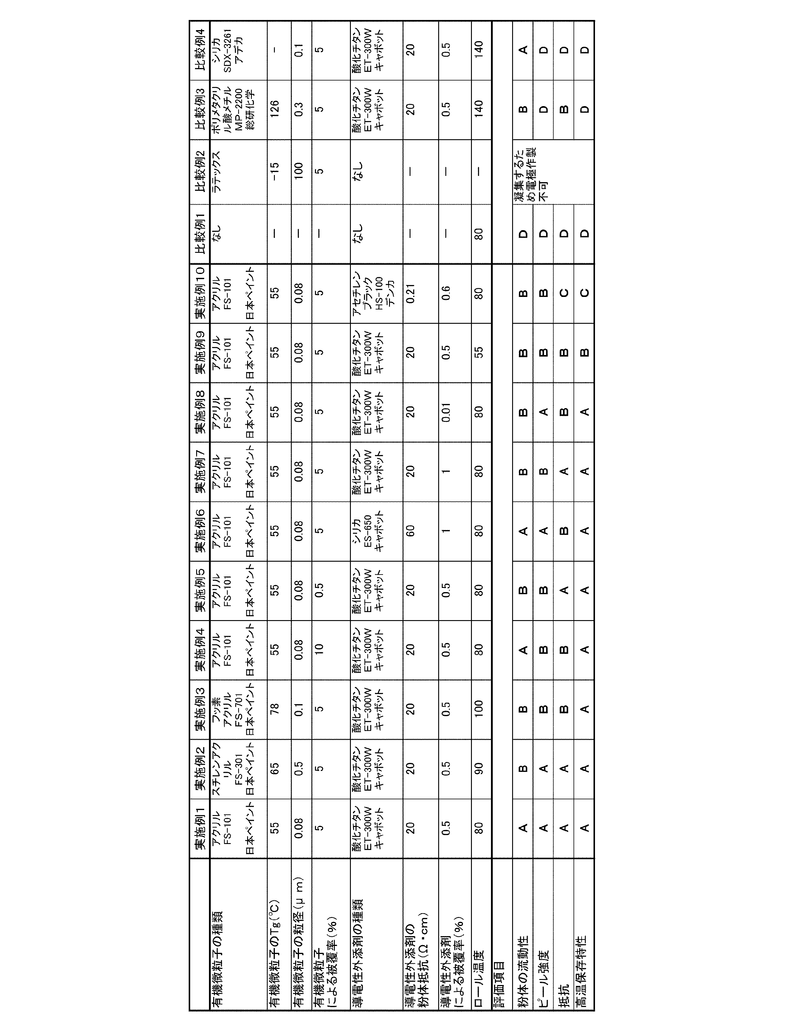
以上より、外添粒子に用いる外添剤が、ガラス転移温度が30℃以上80℃以下である有機微粒子を含んでいると、粉体の流動性に優れ、得られる電気化学素子は、ピール強度、抵抗及び高温保存特性の何れも良好であることが示された。
Claims (10)
- 電極活物質と結着剤とを含む複合粒子の表面を外添剤で被覆した電気化学素子電極用複合粒子であって、
前記外添剤は、ガラス転移温度が30℃以上80℃以下である有機微粒子を含む電気化学素子電極用複合粒子。 - 前記有機微粒子により被覆される被覆率が0.1~20%である請求項1記載の電気化学素子電極用複合粒子。
- 前記外添剤は、粉体抵抗が100Ω・cm未満である導電性外添剤をさらに含む請求項1または2記載の電気化学素子電極用複合粒子。
- 前記導電性外添剤により被覆される被覆率が0.01~2%である請求項3記載の電気化学素子電極用複合粒子。
- 請求項1~4の何れかに記載の電気化学素子電極用複合粒子の製造方法であって、少なくとも結着剤と溶媒とを含む混合物を分散させスラリーを得る工程(I)と、
前記スラリーを噴霧乾燥して複合粒子を得る工程(II)と、
前記複合粒子と外添剤を乾式混合する工程(III)とを含み、前記工程(I)において、前記混合物に電極活物質をさらに含有させるか、又は前記工程(II)において、加熱された気流中に電極活物質を流動させ、そこにスラリーを噴霧して乾燥させる、電気化学素子電極用複合粒子の製造方法。 - 請求項1~4の何れか一項に記載の電気化学素子電極用複合粒子を含んでなる電気化学素子電極材料。
- 請求項6に記載の電気化学素子電極材料から形成される活物質層を集電体上に積層してなる電気化学素子電極。
- 前記活物質層は、加圧成形により前記集電体上に積層される請求項7記載の電気化学素子電極。
- 前記加圧成形は、ロール加圧成形である請求項8記載の電気化学素子電極。
- 前記ロール加圧成形におけるロール温度は、前記有機微粒子のガラス転移温度よりも10℃以上50℃未満高い請求項9記載の電気化学素子電極。
Priority Applications (1)
| Application Number | Priority Date | Filing Date | Title |
|---|---|---|---|
| JP2014502367A JP6281488B2 (ja) | 2012-02-29 | 2013-02-28 | リチウムイオン二次電池電極用複合粒子、リチウムイオン二次電池電極用複合粒子の製造方法、リチウムイオン二次電池電極材料、リチウムイオン二次電池電極及びリチウムイオン二次電池電極の製造方法 |
Applications Claiming Priority (2)
| Application Number | Priority Date | Filing Date | Title |
|---|---|---|---|
| JP2012-043388 | 2012-02-29 | ||
| JP2012043388 | 2012-02-29 |
Publications (1)
| Publication Number | Publication Date |
|---|---|
| WO2013129571A1 true WO2013129571A1 (ja) | 2013-09-06 |
Family
ID=49082762
Family Applications (1)
| Application Number | Title | Priority Date | Filing Date |
|---|---|---|---|
| PCT/JP2013/055400 Ceased WO2013129571A1 (ja) | 2012-02-29 | 2013-02-28 | 電気化学素子電極用複合粒子、電気化学素子電極用複合粒子の製造方法、電気化学素子電極材料及び電気化学素子電極 |
Country Status (2)
| Country | Link |
|---|---|
| JP (1) | JP6281488B2 (ja) |
| WO (1) | WO2013129571A1 (ja) |
Cited By (4)
| Publication number | Priority date | Publication date | Assignee | Title |
|---|---|---|---|---|
| JP2016152169A (ja) * | 2015-02-18 | 2016-08-22 | トヨタ自動車株式会社 | 電極の製造方法 |
| JP2023122455A (ja) * | 2022-02-22 | 2023-09-01 | Apb株式会社 | 電極の製造方法 |
| WO2024117227A1 (ja) * | 2022-11-30 | 2024-06-06 | 日本ゼオン株式会社 | 非水系二次電池電極用複合粒子及びその製造方法、非水系二次電池用負極、並びに、非水系二次電池 |
| US12009520B2 (en) | 2018-04-26 | 2024-06-11 | Samsung Sdi Co., Ltd. | Secondary lithium battery anode and secondary lithium battery including same |
Families Citing this family (1)
| Publication number | Priority date | Publication date | Assignee | Title |
|---|---|---|---|---|
| JP7242834B2 (ja) | 2019-03-26 | 2023-03-20 | 株式会社東芝 | 電極、非水電解質電池、及び電池パック |
Citations (6)
| Publication number | Priority date | Publication date | Assignee | Title |
|---|---|---|---|---|
| JPS64649A (en) * | 1987-03-25 | 1989-01-05 | Toshiba Battery Co Ltd | Hydrogen storage alloy electrode and its manufacture |
| JPH01140554A (ja) * | 1987-11-25 | 1989-06-01 | Matsushita Electric Ind Co Ltd | 非水電解液電池 |
| JP2001319656A (ja) * | 2000-05-09 | 2001-11-16 | Matsushita Electric Ind Co Ltd | リチウムイオン電池用活物質粉体とリチウムイオン電池用電極およびその製造方法とリチウムイオン電池 |
| JP2011060701A (ja) * | 2009-09-14 | 2011-03-24 | Hitachi Maxell Ltd | 非水二次電池 |
| JP2011060432A (ja) * | 2009-09-04 | 2011-03-24 | Ube Industries Ltd | 微細な炭素繊維で覆われた粒子 |
| JP2011134618A (ja) * | 2009-12-25 | 2011-07-07 | Toyo Ink Sc Holdings Co Ltd | 非水系二次電池電極用バインダー組成物 |
Family Cites Families (3)
| Publication number | Priority date | Publication date | Assignee | Title |
|---|---|---|---|---|
| JP5471307B2 (ja) * | 2009-10-29 | 2014-04-16 | 日本ゼオン株式会社 | 電気化学素子用電極の製造方法、電気化学素子用電極及び電気化学素子 |
| JP2012138319A (ja) * | 2010-12-28 | 2012-07-19 | Hitachi Ltd | リチウムイオン二次電池 |
| CN103563133B (zh) * | 2011-05-31 | 2016-08-17 | 日本瑞翁株式会社 | 锂二次电池正极用复合粒子、锂二次电池正极用复合粒子的制造方法、锂二次电池用正极的制造方法、锂二次电池用正极、及锂二次电池 |
-
2013
- 2013-02-28 JP JP2014502367A patent/JP6281488B2/ja active Active
- 2013-02-28 WO PCT/JP2013/055400 patent/WO2013129571A1/ja not_active Ceased
Patent Citations (6)
| Publication number | Priority date | Publication date | Assignee | Title |
|---|---|---|---|---|
| JPS64649A (en) * | 1987-03-25 | 1989-01-05 | Toshiba Battery Co Ltd | Hydrogen storage alloy electrode and its manufacture |
| JPH01140554A (ja) * | 1987-11-25 | 1989-06-01 | Matsushita Electric Ind Co Ltd | 非水電解液電池 |
| JP2001319656A (ja) * | 2000-05-09 | 2001-11-16 | Matsushita Electric Ind Co Ltd | リチウムイオン電池用活物質粉体とリチウムイオン電池用電極およびその製造方法とリチウムイオン電池 |
| JP2011060432A (ja) * | 2009-09-04 | 2011-03-24 | Ube Industries Ltd | 微細な炭素繊維で覆われた粒子 |
| JP2011060701A (ja) * | 2009-09-14 | 2011-03-24 | Hitachi Maxell Ltd | 非水二次電池 |
| JP2011134618A (ja) * | 2009-12-25 | 2011-07-07 | Toyo Ink Sc Holdings Co Ltd | 非水系二次電池電極用バインダー組成物 |
Cited By (4)
| Publication number | Priority date | Publication date | Assignee | Title |
|---|---|---|---|---|
| JP2016152169A (ja) * | 2015-02-18 | 2016-08-22 | トヨタ自動車株式会社 | 電極の製造方法 |
| US12009520B2 (en) | 2018-04-26 | 2024-06-11 | Samsung Sdi Co., Ltd. | Secondary lithium battery anode and secondary lithium battery including same |
| JP2023122455A (ja) * | 2022-02-22 | 2023-09-01 | Apb株式会社 | 電極の製造方法 |
| WO2024117227A1 (ja) * | 2022-11-30 | 2024-06-06 | 日本ゼオン株式会社 | 非水系二次電池電極用複合粒子及びその製造方法、非水系二次電池用負極、並びに、非水系二次電池 |
Also Published As
| Publication number | Publication date |
|---|---|
| JPWO2013129571A1 (ja) | 2015-07-30 |
| JP6281488B2 (ja) | 2018-02-21 |
Similar Documents
| Publication | Publication Date | Title |
|---|---|---|
| KR101245055B1 (ko) | 전기화학 소자 전극용 복합 입자, 전기화학 소자 전극용 복합 입자의 제조 방법 및 전기화학 소자 전극 | |
| JP5201313B2 (ja) | 電気化学素子用電極およびその製造方法 | |
| WO2013128776A1 (ja) | 電気化学素子電極用複合粒子、電気化学素子電極用複合粒子の製造方法、電気化学素子電極材料及び電気化学素子電極 | |
| CN101410915B (zh) | 电化学元件电极用复合粒子、电化学元件电极用复合粒子的制造方法及电化学元件电极 | |
| JP6217741B2 (ja) | 電気化学素子電極用複合粒子、電気化学素子電極用複合粒子の製造方法、電気化学素子電極および電気化学素子 | |
| JP6344384B2 (ja) | 電気化学素子電極用複合粒子、電気化学素子電極用複合粒子の製造方法、電気化学素子電極および電気化学素子 | |
| JP5141002B2 (ja) | 電気化学素子電極用複合粒子の製造方法 | |
| JP2012129536A (ja) | 電気化学素子電極材料および複合粒子 | |
| JP6380526B2 (ja) | 電気化学素子電極用複合粒子 | |
| JP5999237B2 (ja) | 粉体圧延装置及び圧延シートの製造方法 | |
| WO2013031854A1 (ja) | 粉体成形装置及び粉体成形物の製造方法 | |
| JP2013077558A (ja) | 電気化学素子用電極 | |
| WO2013011936A1 (ja) | 電気化学素子電極用複合粒子、電気化学素子電極材料、及び電気化学素子電極 | |
| JP6281488B2 (ja) | リチウムイオン二次電池電極用複合粒子、リチウムイオン二次電池電極用複合粒子の製造方法、リチウムイオン二次電池電極材料、リチウムイオン二次電池電極及びリチウムイオン二次電池電極の製造方法 | |
| JP6485359B2 (ja) | 電気化学素子電極用複合粒子 | |
| JP2013041819A (ja) | 電気化学素子負極電極用複合粒子、電気化学素子負極電極材料、及び電気化学素子負極電極 | |
| JP5311706B2 (ja) | 電気化学素子電極用複合粒子の製造方法 | |
| JP5790353B2 (ja) | 粉体圧延装置及び圧延シートの製造方法 | |
| WO2013118758A1 (ja) | 電気化学素子電極用複合粒子の製造装置及び電気化学素子電極用複合粒子の製造方法 | |
| JP5845748B2 (ja) | 粉体圧延装置及び圧延シートの製造方法 | |
| JP2006060193A (ja) | 複合粒子の製造方法 | |
| JP2013062202A (ja) | 電極成形装置及び電極成形方法 |
Legal Events
| Date | Code | Title | Description |
|---|---|---|---|
| 121 | Ep: the epo has been informed by wipo that ep was designated in this application |
Ref document number: 13755527 Country of ref document: EP Kind code of ref document: A1 |
|
| ENP | Entry into the national phase |
Ref document number: 2014502367 Country of ref document: JP Kind code of ref document: A |
|
| NENP | Non-entry into the national phase |
Ref country code: DE |
|
| 122 | Ep: pct application non-entry in european phase |
Ref document number: 13755527 Country of ref document: EP Kind code of ref document: A1 |