WO2013129262A1 - 発泡樹脂芯材複合板の締結構造 - Google Patents
発泡樹脂芯材複合板の締結構造 Download PDFInfo
- Publication number
- WO2013129262A1 WO2013129262A1 PCT/JP2013/054597 JP2013054597W WO2013129262A1 WO 2013129262 A1 WO2013129262 A1 WO 2013129262A1 JP 2013054597 W JP2013054597 W JP 2013054597W WO 2013129262 A1 WO2013129262 A1 WO 2013129262A1
- Authority
- WO
- WIPO (PCT)
- Prior art keywords
- foamed resin
- fastening
- core material
- hole
- composite plate
- Prior art date
- Legal status (The legal status is an assumption and is not a legal conclusion. Google has not performed a legal analysis and makes no representation as to the accuracy of the status listed.)
- Ceased
Links
Images


Classifications
-
- F—MECHANICAL ENGINEERING; LIGHTING; HEATING; WEAPONS; BLASTING
- F16—ENGINEERING ELEMENTS AND UNITS; GENERAL MEASURES FOR PRODUCING AND MAINTAINING EFFECTIVE FUNCTIONING OF MACHINES OR INSTALLATIONS; THERMAL INSULATION IN GENERAL
- F16B—DEVICES FOR FASTENING OR SECURING CONSTRUCTIONAL ELEMENTS OR MACHINE PARTS TOGETHER, e.g. NAILS, BOLTS, CIRCLIPS, CLAMPS, CLIPS OR WEDGES; JOINTS OR JOINTING
- F16B5/00—Joining sheets or plates, e.g. panels, to one another or to strips or bars parallel to them
- F16B5/0096—Joining sheets or plates, e.g. panels, to one another or to strips or bars parallel to them by using permanent deformation
-
- B—PERFORMING OPERATIONS; TRANSPORTING
- B21—MECHANICAL METAL-WORKING WITHOUT ESSENTIALLY REMOVING MATERIAL; PUNCHING METAL
- B21D—WORKING OR PROCESSING OF SHEET METAL OR METAL TUBES, RODS OR PROFILES WITHOUT ESSENTIALLY REMOVING MATERIAL; PUNCHING METAL
- B21D39/00—Application of procedures in order to connect objects or parts, e.g. coating with sheet metal otherwise than by plating; Tube expanders
- B21D39/03—Application of procedures in order to connect objects or parts, e.g. coating with sheet metal otherwise than by plating; Tube expanders of sheet metal otherwise than by folding
- B21D39/031—Joining superposed plates by locally deforming without slitting or piercing
- B21D39/032—Joining superposed plates by locally deforming without slitting or piercing by fitting a projecting part integral with one plate in a hole of the other plate
-
- B—PERFORMING OPERATIONS; TRANSPORTING
- B21—MECHANICAL METAL-WORKING WITHOUT ESSENTIALLY REMOVING MATERIAL; PUNCHING METAL
- B21J—FORGING; HAMMERING; PRESSING METAL; RIVETING; FORGE FURNACES
- B21J15/00—Riveting
- B21J15/02—Riveting procedures
- B21J15/04—Riveting hollow rivets mechanically
-
- B—PERFORMING OPERATIONS; TRANSPORTING
- B23—MACHINE TOOLS; METAL-WORKING NOT OTHERWISE PROVIDED FOR
- B23K—SOLDERING OR UNSOLDERING; WELDING; CLADDING OR PLATING BY SOLDERING OR WELDING; CUTTING BY APPLYING HEAT LOCALLY, e.g. FLAME CUTTING; WORKING BY LASER BEAM
- B23K11/00—Resistance welding; Severing by resistance heating
- B23K11/002—Resistance welding; Severing by resistance heating specially adapted for particular articles or work
-
- B—PERFORMING OPERATIONS; TRANSPORTING
- B60—VEHICLES IN GENERAL
- B60R—VEHICLES, VEHICLE FITTINGS, OR VEHICLE PARTS, NOT OTHERWISE PROVIDED FOR
- B60R13/00—Elements for body-finishing, identifying, or decorating; Arrangements or adaptations for advertising purposes
- B60R13/02—Internal Trim mouldings ; Internal Ledges; Wall liners for passenger compartments; Roof liners
- B60R13/0206—Arrangements of fasteners and clips specially adapted for attaching inner vehicle liners or mouldings
-
- F—MECHANICAL ENGINEERING; LIGHTING; HEATING; WEAPONS; BLASTING
- F16—ENGINEERING ELEMENTS AND UNITS; GENERAL MEASURES FOR PRODUCING AND MAINTAINING EFFECTIVE FUNCTIONING OF MACHINES OR INSTALLATIONS; THERMAL INSULATION IN GENERAL
- F16B—DEVICES FOR FASTENING OR SECURING CONSTRUCTIONAL ELEMENTS OR MACHINE PARTS TOGETHER, e.g. NAILS, BOLTS, CIRCLIPS, CLAMPS, CLIPS OR WEDGES; JOINTS OR JOINTING
- F16B13/00—Dowels or other devices fastened in walls or the like by inserting them in holes made therein for that purpose
-
- F—MECHANICAL ENGINEERING; LIGHTING; HEATING; WEAPONS; BLASTING
- F16—ENGINEERING ELEMENTS AND UNITS; GENERAL MEASURES FOR PRODUCING AND MAINTAINING EFFECTIVE FUNCTIONING OF MACHINES OR INSTALLATIONS; THERMAL INSULATION IN GENERAL
- F16B—DEVICES FOR FASTENING OR SECURING CONSTRUCTIONAL ELEMENTS OR MACHINE PARTS TOGETHER, e.g. NAILS, BOLTS, CIRCLIPS, CLAMPS, CLIPS OR WEDGES; JOINTS OR JOINTING
- F16B19/00—Bolts without screw-thread; Pins, including deformable elements; Rivets
- F16B19/02—Bolts or sleeves for positioning of machine parts, e.g. notched taper pins, fitting pins, sleeves, eccentric positioning rings
-
- F—MECHANICAL ENGINEERING; LIGHTING; HEATING; WEAPONS; BLASTING
- F16—ENGINEERING ELEMENTS AND UNITS; GENERAL MEASURES FOR PRODUCING AND MAINTAINING EFFECTIVE FUNCTIONING OF MACHINES OR INSTALLATIONS; THERMAL INSULATION IN GENERAL
- F16B—DEVICES FOR FASTENING OR SECURING CONSTRUCTIONAL ELEMENTS OR MACHINE PARTS TOGETHER, e.g. NAILS, BOLTS, CIRCLIPS, CLAMPS, CLIPS OR WEDGES; JOINTS OR JOINTING
- F16B19/00—Bolts without screw-thread; Pins, including deformable elements; Rivets
- F16B19/04—Rivets; Spigots or the like fastened by riveting
- F16B19/08—Hollow rivets; Multi-part rivets
-
- F—MECHANICAL ENGINEERING; LIGHTING; HEATING; WEAPONS; BLASTING
- F16—ENGINEERING ELEMENTS AND UNITS; GENERAL MEASURES FOR PRODUCING AND MAINTAINING EFFECTIVE FUNCTIONING OF MACHINES OR INSTALLATIONS; THERMAL INSULATION IN GENERAL
- F16B—DEVICES FOR FASTENING OR SECURING CONSTRUCTIONAL ELEMENTS OR MACHINE PARTS TOGETHER, e.g. NAILS, BOLTS, CIRCLIPS, CLAMPS, CLIPS OR WEDGES; JOINTS OR JOINTING
- F16B5/00—Joining sheets or plates, e.g. panels, to one another or to strips or bars parallel to them
- F16B5/04—Joining sheets or plates, e.g. panels, to one another or to strips or bars parallel to them by means of riveting
-
- F—MECHANICAL ENGINEERING; LIGHTING; HEATING; WEAPONS; BLASTING
- F16—ENGINEERING ELEMENTS AND UNITS; GENERAL MEASURES FOR PRODUCING AND MAINTAINING EFFECTIVE FUNCTIONING OF MACHINES OR INSTALLATIONS; THERMAL INSULATION IN GENERAL
- F16B—DEVICES FOR FASTENING OR SECURING CONSTRUCTIONAL ELEMENTS OR MACHINE PARTS TOGETHER, e.g. NAILS, BOLTS, CIRCLIPS, CLAMPS, CLIPS OR WEDGES; JOINTS OR JOINTING
- F16B5/00—Joining sheets or plates, e.g. panels, to one another or to strips or bars parallel to them
- F16B5/08—Joining sheets or plates, e.g. panels, to one another or to strips or bars parallel to them by means of welds or the like
-
- B—PERFORMING OPERATIONS; TRANSPORTING
- B29—WORKING OF PLASTICS; WORKING OF SUBSTANCES IN A PLASTIC STATE IN GENERAL
- B29C—SHAPING OR JOINING OF PLASTICS; SHAPING OF MATERIAL IN A PLASTIC STATE, NOT OTHERWISE PROVIDED FOR; AFTER-TREATMENT OF THE SHAPED PRODUCTS, e.g. REPAIRING
- B29C65/00—Joining or sealing of preformed parts, e.g. welding of plastics materials; Apparatus therefor
- B29C65/56—Joining or sealing of preformed parts, e.g. welding of plastics materials; Apparatus therefor using mechanical means or mechanical connections, e.g. form-fits
- B29C65/562—Joining or sealing of preformed parts, e.g. welding of plastics materials; Apparatus therefor using mechanical means or mechanical connections, e.g. form-fits using extra joining elements, i.e. which are not integral with the parts to be joined
-
- B—PERFORMING OPERATIONS; TRANSPORTING
- B29—WORKING OF PLASTICS; WORKING OF SUBSTANCES IN A PLASTIC STATE IN GENERAL
- B29C—SHAPING OR JOINING OF PLASTICS; SHAPING OF MATERIAL IN A PLASTIC STATE, NOT OTHERWISE PROVIDED FOR; AFTER-TREATMENT OF THE SHAPED PRODUCTS, e.g. REPAIRING
- B29C65/00—Joining or sealing of preformed parts, e.g. welding of plastics materials; Apparatus therefor
- B29C65/56—Joining or sealing of preformed parts, e.g. welding of plastics materials; Apparatus therefor using mechanical means or mechanical connections, e.g. form-fits
- B29C65/64—Joining a non-plastics element to a plastics element, e.g. by force
-
- B—PERFORMING OPERATIONS; TRANSPORTING
- B29—WORKING OF PLASTICS; WORKING OF SUBSTANCES IN A PLASTIC STATE IN GENERAL
- B29C—SHAPING OR JOINING OF PLASTICS; SHAPING OF MATERIAL IN A PLASTIC STATE, NOT OTHERWISE PROVIDED FOR; AFTER-TREATMENT OF THE SHAPED PRODUCTS, e.g. REPAIRING
- B29C66/00—General aspects of processes or apparatus for joining preformed parts
- B29C66/01—General aspects dealing with the joint area or with the area to be joined
- B29C66/05—Particular design of joint configurations
- B29C66/20—Particular design of joint configurations particular design of the joint lines, e.g. of the weld lines
- B29C66/21—Particular design of joint configurations particular design of the joint lines, e.g. of the weld lines said joint lines being formed by a single dot or dash or by several dots or dashes, i.e. spot joining or spot welding
-
- B—PERFORMING OPERATIONS; TRANSPORTING
- B29—WORKING OF PLASTICS; WORKING OF SUBSTANCES IN A PLASTIC STATE IN GENERAL
- B29C—SHAPING OR JOINING OF PLASTICS; SHAPING OF MATERIAL IN A PLASTIC STATE, NOT OTHERWISE PROVIDED FOR; AFTER-TREATMENT OF THE SHAPED PRODUCTS, e.g. REPAIRING
- B29C66/00—General aspects of processes or apparatus for joining preformed parts
- B29C66/70—General aspects of processes or apparatus for joining preformed parts characterised by the composition, physical properties or the structure of the material of the parts to be joined; Joining with non-plastics material
- B29C66/71—General aspects of processes or apparatus for joining preformed parts characterised by the composition, physical properties or the structure of the material of the parts to be joined; Joining with non-plastics material characterised by the composition of the plastics material of the parts to be joined
-
- B—PERFORMING OPERATIONS; TRANSPORTING
- B29—WORKING OF PLASTICS; WORKING OF SUBSTANCES IN A PLASTIC STATE IN GENERAL
- B29C—SHAPING OR JOINING OF PLASTICS; SHAPING OF MATERIAL IN A PLASTIC STATE, NOT OTHERWISE PROVIDED FOR; AFTER-TREATMENT OF THE SHAPED PRODUCTS, e.g. REPAIRING
- B29C66/00—General aspects of processes or apparatus for joining preformed parts
- B29C66/70—General aspects of processes or apparatus for joining preformed parts characterised by the composition, physical properties or the structure of the material of the parts to be joined; Joining with non-plastics material
- B29C66/72—General aspects of processes or apparatus for joining preformed parts characterised by the composition, physical properties or the structure of the material of the parts to be joined; Joining with non-plastics material characterised by the structure of the material of the parts to be joined
- B29C66/723—General aspects of processes or apparatus for joining preformed parts characterised by the composition, physical properties or the structure of the material of the parts to be joined; Joining with non-plastics material characterised by the structure of the material of the parts to be joined being multi-layered
- B29C66/7232—General aspects of processes or apparatus for joining preformed parts characterised by the composition, physical properties or the structure of the material of the parts to be joined; Joining with non-plastics material characterised by the structure of the material of the parts to be joined being multi-layered comprising a non-plastics layer
- B29C66/72321—General aspects of processes or apparatus for joining preformed parts characterised by the composition, physical properties or the structure of the material of the parts to be joined; Joining with non-plastics material characterised by the structure of the material of the parts to be joined being multi-layered comprising a non-plastics layer consisting of metals or their alloys
-
- B—PERFORMING OPERATIONS; TRANSPORTING
- B29—WORKING OF PLASTICS; WORKING OF SUBSTANCES IN A PLASTIC STATE IN GENERAL
- B29C—SHAPING OR JOINING OF PLASTICS; SHAPING OF MATERIAL IN A PLASTIC STATE, NOT OTHERWISE PROVIDED FOR; AFTER-TREATMENT OF THE SHAPED PRODUCTS, e.g. REPAIRING
- B29C66/00—General aspects of processes or apparatus for joining preformed parts
- B29C66/70—General aspects of processes or apparatus for joining preformed parts characterised by the composition, physical properties or the structure of the material of the parts to be joined; Joining with non-plastics material
- B29C66/72—General aspects of processes or apparatus for joining preformed parts characterised by the composition, physical properties or the structure of the material of the parts to be joined; Joining with non-plastics material characterised by the structure of the material of the parts to be joined
- B29C66/727—General aspects of processes or apparatus for joining preformed parts characterised by the composition, physical properties or the structure of the material of the parts to be joined; Joining with non-plastics material characterised by the structure of the material of the parts to be joined being porous, e.g. foam
-
- B—PERFORMING OPERATIONS; TRANSPORTING
- B29—WORKING OF PLASTICS; WORKING OF SUBSTANCES IN A PLASTIC STATE IN GENERAL
- B29C—SHAPING OR JOINING OF PLASTICS; SHAPING OF MATERIAL IN A PLASTIC STATE, NOT OTHERWISE PROVIDED FOR; AFTER-TREATMENT OF THE SHAPED PRODUCTS, e.g. REPAIRING
- B29C66/00—General aspects of processes or apparatus for joining preformed parts
- B29C66/70—General aspects of processes or apparatus for joining preformed parts characterised by the composition, physical properties or the structure of the material of the parts to be joined; Joining with non-plastics material
- B29C66/74—Joining plastics material to non-plastics material
- B29C66/742—Joining plastics material to non-plastics material to metals or their alloys
-
- B—PERFORMING OPERATIONS; TRANSPORTING
- B29—WORKING OF PLASTICS; WORKING OF SUBSTANCES IN A PLASTIC STATE IN GENERAL
- B29C—SHAPING OR JOINING OF PLASTICS; SHAPING OF MATERIAL IN A PLASTIC STATE, NOT OTHERWISE PROVIDED FOR; AFTER-TREATMENT OF THE SHAPED PRODUCTS, e.g. REPAIRING
- B29C66/00—General aspects of processes or apparatus for joining preformed parts
- B29C66/80—General aspects of machine operations or constructions and parts thereof
- B29C66/81—General aspects of the pressing elements, i.e. the elements applying pressure on the parts to be joined in the area to be joined, e.g. the welding jaws or clamps
- B29C66/814—General aspects of the pressing elements, i.e. the elements applying pressure on the parts to be joined in the area to be joined, e.g. the welding jaws or clamps characterised by the design of the pressing elements, e.g. of the welding jaws or clamps
- B29C66/8141—General aspects of the pressing elements, i.e. the elements applying pressure on the parts to be joined in the area to be joined, e.g. the welding jaws or clamps characterised by the design of the pressing elements, e.g. of the welding jaws or clamps characterised by the surface geometry of the part of the pressing elements, e.g. welding jaws or clamps, coming into contact with the parts to be joined
- B29C66/81427—General aspects of the pressing elements, i.e. the elements applying pressure on the parts to be joined in the area to be joined, e.g. the welding jaws or clamps characterised by the design of the pressing elements, e.g. of the welding jaws or clamps characterised by the surface geometry of the part of the pressing elements, e.g. welding jaws or clamps, coming into contact with the parts to be joined comprising a single ridge, e.g. for making a weakening line; comprising a single tooth
-
- B—PERFORMING OPERATIONS; TRANSPORTING
- B29—WORKING OF PLASTICS; WORKING OF SUBSTANCES IN A PLASTIC STATE IN GENERAL
- B29C—SHAPING OR JOINING OF PLASTICS; SHAPING OF MATERIAL IN A PLASTIC STATE, NOT OTHERWISE PROVIDED FOR; AFTER-TREATMENT OF THE SHAPED PRODUCTS, e.g. REPAIRING
- B29C66/00—General aspects of processes or apparatus for joining preformed parts
- B29C66/80—General aspects of machine operations or constructions and parts thereof
- B29C66/81—General aspects of the pressing elements, i.e. the elements applying pressure on the parts to be joined in the area to be joined, e.g. the welding jaws or clamps
- B29C66/814—General aspects of the pressing elements, i.e. the elements applying pressure on the parts to be joined in the area to be joined, e.g. the welding jaws or clamps characterised by the design of the pressing elements, e.g. of the welding jaws or clamps
- B29C66/8141—General aspects of the pressing elements, i.e. the elements applying pressure on the parts to be joined in the area to be joined, e.g. the welding jaws or clamps characterised by the design of the pressing elements, e.g. of the welding jaws or clamps characterised by the surface geometry of the part of the pressing elements, e.g. welding jaws or clamps, coming into contact with the parts to be joined
- B29C66/81431—General aspects of the pressing elements, i.e. the elements applying pressure on the parts to be joined in the area to be joined, e.g. the welding jaws or clamps characterised by the design of the pressing elements, e.g. of the welding jaws or clamps characterised by the surface geometry of the part of the pressing elements, e.g. welding jaws or clamps, coming into contact with the parts to be joined comprising a single cavity, e.g. a groove
-
- B—PERFORMING OPERATIONS; TRANSPORTING
- B29—WORKING OF PLASTICS; WORKING OF SUBSTANCES IN A PLASTIC STATE IN GENERAL
- B29C—SHAPING OR JOINING OF PLASTICS; SHAPING OF MATERIAL IN A PLASTIC STATE, NOT OTHERWISE PROVIDED FOR; AFTER-TREATMENT OF THE SHAPED PRODUCTS, e.g. REPAIRING
- B29C66/00—General aspects of processes or apparatus for joining preformed parts
- B29C66/80—General aspects of machine operations or constructions and parts thereof
- B29C66/83—General aspects of machine operations or constructions and parts thereof characterised by the movement of the joining or pressing tools
- B29C66/832—Reciprocating joining or pressing tools
- B29C66/8322—Joining or pressing tools reciprocating along one axis
-
- B—PERFORMING OPERATIONS; TRANSPORTING
- B29—WORKING OF PLASTICS; WORKING OF SUBSTANCES IN A PLASTIC STATE IN GENERAL
- B29L—INDEXING SCHEME ASSOCIATED WITH SUBCLASS B29C, RELATING TO PARTICULAR ARTICLES
- B29L2031/00—Other particular articles
- B29L2031/737—Articles provided with holes, e.g. grids, sieves
-
- F—MECHANICAL ENGINEERING; LIGHTING; HEATING; WEAPONS; BLASTING
- F16—ENGINEERING ELEMENTS AND UNITS; GENERAL MEASURES FOR PRODUCING AND MAINTAINING EFFECTIVE FUNCTIONING OF MACHINES OR INSTALLATIONS; THERMAL INSULATION IN GENERAL
- F16B—DEVICES FOR FASTENING OR SECURING CONSTRUCTIONAL ELEMENTS OR MACHINE PARTS TOGETHER, e.g. NAILS, BOLTS, CIRCLIPS, CLAMPS, CLIPS OR WEDGES; JOINTS OR JOINTING
- F16B5/00—Joining sheets or plates, e.g. panels, to one another or to strips or bars parallel to them
- F16B5/01—Joining sheets or plates, e.g. panels, to one another or to strips or bars parallel to them by means of fastening elements specially adapted for honeycomb panels
-
- Y—GENERAL TAGGING OF NEW TECHNOLOGICAL DEVELOPMENTS; GENERAL TAGGING OF CROSS-SECTIONAL TECHNOLOGIES SPANNING OVER SEVERAL SECTIONS OF THE IPC; TECHNICAL SUBJECTS COVERED BY FORMER USPC CROSS-REFERENCE ART COLLECTIONS [XRACs] AND DIGESTS
- Y10—TECHNICAL SUBJECTS COVERED BY FORMER USPC
- Y10T—TECHNICAL SUBJECTS COVERED BY FORMER US CLASSIFICATION
- Y10T403/00—Joints and connections
- Y10T403/49—Member deformed in situ
- Y10T403/4949—Deforming component is inserted section
Definitions
- the present invention relates to a fastening structure of a foamed resin core material composite plate for fastening a foamed resin core material composite plate to a counterpart member.
- a core composite plate may be used (see, for example, Patent Document 1). These are intended to reduce the weight of the automobile, to provide damping performance, sound insulation performance, and the like.
- Automobile panel members and cover members are often fastened with other members of the same part, such as frame members, or other members by resistance welding or bolt fastening.
- these members formed of the foamed resin core material composite plate cannot be fastened by resistance welding because a soft foamed resin that does not conduct electricity is interposed as a core material.
- an object of the present invention is to provide a fastening structure of a foamed resin core material composite plate that can be applied with either bolt fastening or resistance welding and can maintain strong fastening with a counterpart member for a long period of time. is there.
- the present invention is a fastening structure of a foamed resin core material composite plate in which a foamed resin core material composite plate laminated with a foamed resin core material sandwiched between metal plates is fastened to a counterpart member.
- the fastening portion of the foamed resin core material composite plate is provided with a through hole and a crushing peripheral edge portion that crushes the foamed resin core material around the through hole, and is fitted into the through hole.
- the structure which the said fastening member was fastened with the said other party member was employ
- the metal fastening member inserted into the through hole is crushed by crimping or welding and joined to the peripheral portion, and the fastening member is fastened to the other member, so that the metal fastening member is joined by caulking or welding. It is firmly bonded to the fastening portion of the foamed resin core composite plate. Thereby, any fastening of bolt fastening and resistance welding can be applied, and strong fastening with the counterpart member can be maintained for a long period of time.
- the fastening member has a cylindrical shape with a pedestal provided with a pedestal at one end of the cylindrical part, and rises from the periphery of the through hole to the crushing peripheral part.
- a cylindrical vertical wall portion is provided, the cylindrical portion of the fastening member is fitted into the through hole from the proximal end side of the vertical wall portion, the pedestal portion is pressed against the crushing peripheral edge portion, and the vertical wall
- the fastening member may be crimped to the distal end side of the vertical wall portion so as to expand the distal end side of the cylindrical portion protruding from the distal end side of the portion.
- the eyelet-shaped member is placed on the outer side of the vertical wall portion so that the eyelet of the eyelet-shaped member is aligned with the through hole, and the tip end side of the cylindrical portion is the tip side of the vertical wall portion via the eyelet-like member. It may be caulked. Thereby, a fastening member can be combined more firmly so that a vertical wall part may be pinched by a cylindrical part and an eyelet-like member.
- the fastening member has a hat shape having a flange portion at the lower end of the hat portion, and the flange portion is an outer surface of one of the metal plates at a peripheral edge portion of the through hole.
- the foamed resin core material at the peripheral part of the through hole so that the cap part fitted into the through hole is pressed flat to the outer surface side of the other metal plate in a flat shape.
- the fastening member has a dish shape including an inclined wall portion that extends to the outer peripheral side around the bottom portion, and the dish-shaped fastening member is inserted into the through-hole,
- the dish-shaped fastening member By crushing the dish-shaped fastening member together with the foamed resin core at the peripheral edge of the through-hole so as to expand the inclined wall portion into a flat shape toward the foamed resin side between the metal plates,
- the inclined wall portion squeezed and expanded in the flat shape is sandwiched between the metal plates on the front and back sides of the crushing peripheral portion, and the sandwiched inclined wall portions are welded to the metal plates on the front and back sides of the crushing peripheral portion. It may be a thing.
- the rigidity in the vicinity of the fastening portion can be increased by forming the step portion on the outer peripheral side of the fastening portion of the foamed resin core material composite plate.
- the stepped portion After the stepped portion is formed in the unfoamed state, the stepped portion can be easily formed by press molding or the like by foaming the foamed resin. Will not be crushed.
- the fastening structure of the foamed resin core composite plate according to the present invention includes a through hole in the fastening portion of the foam resin core composite plate, and a crushing peripheral portion obtained by crushing the foamed resin core around the through hole.
- the metal fastening member provided and inserted into the through hole is crushed by crimping or welding and joined to the peripheral edge so that the fastening member is fastened to the counterpart member. Can be applied, and strong fastening with the counterpart member can be maintained.
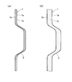
- the longitudinal cross-sectional view which shows the fastening structure of the foaming resin core material composite board of 1st Embodiment (A), (b) is sectional drawing which shows the process in which a level
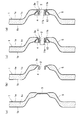
- step-difference part is formed in the foaming resin core material composite board of FIG. (A)-(d) is sectional drawing which shows the process in which the fastening structure of FIG. 1 is formed.
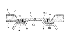
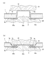
- the longitudinal cross-sectional view which shows the fastening structure of the foaming resin core material composite board of 2nd Embodiment (A), (b) is sectional drawing which shows the process in which the fastening structure of FIG. 4 is formed.
- FIG. 1, FIG. 2 (a) (b), FIG. 3 (a) (b) (c) (d) shows 1st Embodiment.
- the foamed resin core composite plate 1 is formed by laminating a polyolefin resin foam resin 1c core material between front and back metal plates 1a and 1b, which are steel plates or aluminum plates. Is done.
- the fastening portion of the foamed resin core composite plate 1 is provided with a through hole 2 and a crushing peripheral edge portion 3 a formed by crushing the foamed resin 1 c around the through hole 2.
- the crushing peripheral edge 3 a is provided with a cylindrical vertical wall 4 that rises from the peripheral edge of the through hole 2.
- the metal fastening member 11 provided with the pedestal portion 11b on one end side of the cylindrical portion 11a is fitted into the through hole 2 from the base end side of the vertical wall portion 4 so as to crush the pedestal portion 11b and press it against the peripheral edge portion 3a. Inserted.
- the eyelet-shaped member 12 is put on the outside of the vertical wall portion 4, and the eyelet of the eyelet-shaped member 12 is aligned with the through hole 2.
- the fastening member 11 is crimped to the distal end side of the vertical wall portion 4 via the eyelet-shaped member 12 so as to expand the distal end side of the cylindrical portion 11a protruding from the distal end side of the vertical wall portion 4, and is a foamed resin core material
- the composite plate 1 is firmly coupled to the fastening portion.
- Bolts 13 are inserted into the penetrating cylindrical portion 11a, and the fastening member 11 and the counterpart member A are bolted together by tightening the fastening member 11 and the counterpart member A with the nut 14.
- a step part 5 is formed for increasing the rigidity in the vicinity of the fastening part.
- FIG. 2 shows a process of forming the stepped portion 5 of the foamed resin core material composite plate 1.
- step-difference part 5 is formed in the state by which the foamed resin 1c is unfoamed.
- the foamed resin 1 c is foamed by heating the foamed resin core material composite plate 1 on which the step portions 5 are formed. Accordingly, the stepped portion 5 can be easily formed by press molding or the like, and the foamed resin 1c of the stepped portion 5 is not crushed during the forming.
- FIG. 3A a crushing portion 3 that crushes the foamed resin 1 c is formed around the fastening portion of the foamed resin core composite plate 1 by press working.
- FIG.3 (b) by punching the through-hole 2 in the fastening part of the center of the crushing part 3, the crushing peripheral part 3a by which the through-hole 2 was pierced from the periphery of the through-hole 2 is carried out.
- a cylindrical vertical wall portion 4 that rises is formed.
- the cylindrical portion 11a of the fastening member 11 is fitted and inserted from the base end side of the vertical wall portion 4, and the pedestal portion 11b is crushed and pressed against the peripheral edge portion 3a.
- the eyelet-shaped member 12 is put on the outer side of the front end surface and the outer peripheral surface of the vertical wall portion 4.
- the fastening member 11 is the vertical wall part 4 via the eyelet-shaped member 12 so that the front end side of the cylindrical part 11a which protrudes from the front end side of the vertical wall part 4 may be expanded. It can be crimped on the tip side.
- the other member A is bolted to the fastening member 11 by fastening the fastening member 11 and the other member A with the bolt 13 and the nut 14 that are fitted and inserted into the cylindrical portion 11 a. .
- the fastening member 11 and the counterpart member A are fastened by bolt fastening.
- the pedestal portion 11b and the counterpart member A can be fastened by resistance welding by a configuration in which the pedestal portion 11b of the fastening member 11 closes one end side of the cylindrical portion 11a.
- FIG. 4 and 5 (a) and 5 (b) show a second embodiment.
- a hat-shaped metal fastening member 15 having a flange portion 15b at the lower end of the hat portion 15a is used.
- a through hole 2 is provided in the fastening portion of the foamed resin core composite plate 1 similar to that of the first embodiment.
- the cap portion 15 a of the fastening member 15 is fitted into the through hole 2, and the flange portion 15 b is pressed against the lower surface side of the back metal plate 1 b around the through hole 2.
- the fastening member 15 crushes the inserted cap portion 15a together with the core material of the foamed resin 1c around the through-hole 2 so as to be expanded in a flat shape toward the upper surface side of the front metal plate 1a.
- the cap portion 15a and the flange portion 15b which are expanded in a flat shape, sandwich the metal plates 1a, 1b on the front and back of the crushed peripheral portion 3a around the through hole 2 where the foamed resin 1c is crushed, It is firmly coupled to the metal plates 1a and 1b by resistance welding 16a.
- the counterpart member A is fastened to the ceiling portion of the cap portion 15a that closes the through hole 2 by resistance welding 17a.
- a stepped portion for increasing rigidity is formed on the outer peripheral side of the fastening portion of the foamed resin core composite plate 1 as in the first embodiment.
- FIGS. 5A and 5B show a process of forming the fastening structure of the second embodiment.
- the cap part 15a of the fastening member 15 is inserted by insertion in the through-hole 2 provided in the fastening part of the foamed resin core material composite board 1 from the downward direction.
- the fastening member 15 is set between the punch 21 and the die 22 by pressing the flange portion 15 b against the lower surface side of the metal plate 1 b on the back side at the peripheral edge portion of the through hole 2.
- the punch 21 is a flat head punch.
- the die 22 is formed with a circular convex portion 22a that fits into the cap portion 15a and an annular concave portion 22b into which the flange portion 15b fits on the die surface with which the metal plate 1b abuts.
- the punch 21 is lowered to a position where the ceiling portion of the cap portion 15 a hits the convex portion 22 a of the die 22.
- the punch 21 crushes the cap portion 15a together with the foamed resin 1c around the through hole 2 so as to expand the cap portion 15a in a flat shape toward the upper surface side of the front metal plate 1a.
- the metal plates 1a and 1b on the front and back sides of the crushing peripheral edge portion 3a in which the foamed resin 1c is crushed are sandwiched between the cap portion 15a and the flange portion 15b that are expanded in a flat shape.
- the expanded cap portion 15a and the flange portion 15b are joined to the front and back metal plates 1a and 1b by resistance welding 16a, and the mating member A is attached to the ceiling portion of the cap portion 15a. Fastened by resistance welding 17a.
- the metal plates 1a and 1b on the front and back sides of the foamed resin core composite plate 1 are aluminum alloy plates
- the metal plate 1a of the aluminum alloy plate is formed by forming the metal fastening member 15 with an aluminum-plated steel plate. The welding strength with 1b can be increased.
- the surface plating layer of the fastening member 15 is aluminum with a high heat ray reflectance, the effect which prevents the heat conduction to the foamed resin 1c by the fastening member 15 absorbing a heat ray can also be anticipated.
- FIGS. 6, 7 and 8 (a) and 8 (b) show a third embodiment.
- a dish-shaped metal fastening member 18 having an inclined wall portion 18 b that extends to the outer peripheral side around the bottom portion 18 a is used.
- the through hole 2 is provided in the fastening portion of the foamed resin core material composite plate 1 similar to the first embodiment, and the fastening member 18 is inserted into the through hole 2.
- the inclined wall portion 18b is crushed together with the foamed resin 1c around the through hole 2 so as to be expanded in a flat shape toward the foamed resin 1c side between the front and back metal plates 1a, 1b.
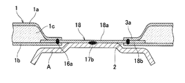
- the inclined wall portion 18b expanded so as to be sandwiched between the metal plates 1a and 1b of the crushing peripheral edge portion 3a around the through-hole 2 where the foamed resin 1c is crushed is formed by resistance welding 16b and the metal on the front and back sides. It is firmly coupled to the plates 1a and 1b.
- the counterpart member A is fastened to the bottom 18a of the fastening member 18 by resistance welding 17b.
- a stepped portion for increasing rigidity is formed on the outer peripheral side of the fastening portion of the foamed resin core composite plate 1 as in the first embodiment.
- FIG. 7 shows the dish-shaped fastening member 18.
- the inclined wall portion 18b is provided with a flat portion 18c having no inclination on the outer peripheral side in order to facilitate the deformation of the crushing peripheral edge portion 3a between the metal plates 1a and 1b.
- the notch 18d is inserted. Note that a plurality of the fastening members 18 can be used in a stacked manner.
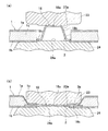
- FIG. 8A and 8B show a process of forming the fastening structure of the third embodiment.
- a dish-shaped fastening member 18 is inserted into the through-hole 2 provided in the fastening portion of the foamed resin core composite plate 1, and the punch 23 and the die 24 are interposed.
- the punch 23 is provided with a circular step portion 23 a that abuts the fastening member 18, and the die 24 is provided with a circular step portion 24 a on which the fastening member 18 is placed.
- the height of each step part 23a, 24a is formed substantially equal to the thickness of the metal plates 1a, 1b on the front and back sides.
- the punch 23 is lowered.
- the punch 23 crushes the inclined wall portion 18b of the fastening member 18 between the step portions 23a and 24a so as to be expanded in a flat shape toward the foamed resin 1c side between the front and back metal plates 1a and 1b. Further, the punch 23 crushes the foamed resin 1c around the through hole 2 between the punch 23 on the outer peripheral side of each stepped portion 23a, 24a and the die 24.
- the expanded inclined wall portion 18b is sandwiched between the metal plates 1a and 1b on the front and back of the crushed peripheral edge portion 3a in which the foamed resin 1c is crushed.
- the opposing member A is connected to the bottom portion 18 a of the fastening member 18 by resistance welding 17 b by joining the expanded inclined wall portion 18 b to the front and back metal plates 1 a and 1 b by resistance welding 16 b. It is concluded with.
- the counterpart member A is fastened by resistance welding, but the fastening members 15 and 19 and the counterpart member A can be fastened by bolt fastening.
- the metal fastening member is formed in a cylindrical shape with a pedestal, a hat shape, or a dish shape, but is not limited to these embodiments.
- the fastening member may be any member that can be firmly bonded to the crushing peripheral portion of the foamed resin core composite plate by caulking or welding.
- the front and back metal plates of the foamed resin core composite plate are steel plates or aluminum plates, but the front and back metal plates are aluminum plated steel plates, other surface-treated steel plates, surface-treated aluminum alloy plates, etc. Other metal plates can also be used.
- a metal fastening member can be formed with an aluminum plating steel plate, another surface treatment steel plate, an aluminum plywood board, a surface treatment aluminum plywood board, etc.
Landscapes
- Engineering & Computer Science (AREA)
- General Engineering & Computer Science (AREA)
- Mechanical Engineering (AREA)
- Connection Of Plates (AREA)
- Bolts, Nuts, And Washers (AREA)
- Vehicle Interior And Exterior Ornaments, Soundproofing, And Insulation (AREA)
Description
本発明は、発泡樹脂芯材複合板を相手方部材と締結する発泡樹脂芯材複合板の締結構造に関する。
自動車の各種アウタパネル、インナパネル等のパネル部材や、ヒートインシュレータ、フロアアンダカバー等のカバー部材には、鋼板やアルミニウム板等の金属板間に発泡樹脂の芯材を挟むことにより形成される発泡樹脂芯材複合板が用いられることがある(例えば、特許文献1参照)。これらは、自動車の軽量化や、制振性能、遮音性能等の付与を目的としている。
自動車のパネル部材やカバー部材は、抵抗溶接やボルト締結によって、同じパーツの他の部材やフレーム部材等の相手方部材と締結されることが多い。しかしながら、発泡樹脂芯材複合板で形成されたこれらの部材は、電気を通さない軟質の発泡樹脂が芯材として介在するので、抵抗溶接による締結ができない。また、ボルト締結によっても、相手方部材と強固に締結できないという難点がある。
発泡樹脂芯材複合板をボルト締結によって相手方部材と強固に締結する手段としては、複合板に設けたボルト孔にボルトを挿通し、複合板の厚みよりも長い胴部と鍔部からなる円筒状部材をボルトとボルト孔との間に介在させる締結構造が提案されている。この構造では、ボルトで円筒状部材の胴部を締め込むことにより、芯材層側へはみ出し変形した胴部と鍔部または相手方部材との間で表裏の金属板が挟持される。また、同様にボルト孔に挿通したボルトとボルト孔との間に、円錐面を有する複数の皿ばねを介在させる締結構造が提案されている(例えば、特許文献2参照)。この構造では、ボルトで皿ばねを締め込むことにより、扁平に変形して芯材層側へはみ出した皿ばねと座金または相手方部材との間で、表裏の金属板が挟持される。
特許文献2に記載された発泡樹脂芯材複合板の締結構造によれば、締結当初は強固な締結が可能である。しかしながら、このような構造では、ボルトの締め込みにより芯材層側へはみ出す円筒状部材の胴部または皿ばねと表裏面の金属板との間や、複数の皿ばねの層間に、ボルトの締結力が作用する領域で芯材の発泡樹脂が入り込む。この入り込んだ熱膨張係数の大きい発泡樹脂が、気温差、エンジンからの熱等で生じる冷熱サイクルによる膨張、収縮の繰り返しや、車の振動等によって徐々に抜け出すため、ボルトの締結力が経時的に低下するという問題がある。また、この締結構造は、簡便な抵抗溶接による締結には適用できないという問題もある。
そこで、本発明の課題は、ボルト締結と抵抗溶接のいずれの締結も適用でき、相手方部材との強固な締結を長期間維持することができる発泡樹脂芯材複合板の締結構造を提供することである。
上記の課題を解決するために、本発明は、金属板間に発泡樹脂の芯材を挟んで積層した発泡樹脂芯材複合板を相手方部材と締結する発泡樹脂芯材複合板の締結構造であって、前記発泡樹脂芯材複合板の締結部に、貫通孔と、この貫通孔の周囲で前記発泡樹脂の芯材を押し潰した押し潰し周縁部と、が設けられ、前記貫通孔に嵌挿された金属製の締結部材をカシメ付けまたは溶接によって前記押し潰し周縁部に結合することにより、前記締結部材が前記相手方部材と締結される構成を採用した。
すなわち、貫通孔に嵌挿した金属製の締結部材を、カシメ付けまたは溶接によって押し潰し周縁部に結合し、締結部材を相手方部材と締結することにより、カシメ付けまたは溶接によって金属製の締結部材が発泡樹脂芯材複合板の締結部に強固に結合される。これにより、ボルト締結と抵抗溶接のいずれの締結も適用でき、相手方部材との強固な締結を長期間維持できる。
上記発泡樹脂芯材複合板の締結構造は、前記締結部材が、円筒部の一端側に台座部を設けた台座付き円筒形状を有し、前記押し潰し周縁部に、前記貫通孔の周縁から立ち上がる筒状の縦壁部が設けられ、前記締結部材の円筒部を前記縦壁部の基端側から前記貫通孔に嵌挿して、前記台座部を前記押し潰し周縁部に押し当て、前記縦壁部の先端側から突出する前記円筒部の先端側を押し拡げるように、前記締結部材が前記縦壁部の先端側にカシメ付けられるものであってもよい。
鳩目状部材の鳩目を前記貫通孔に合わせるように、前記鳩目状部材が前記縦壁部の外側に被せられ、前記鳩目状部材を介して、前記円筒部の先端側が前記縦壁部の先端側にカシメ付けられるものであってもよい。これにより、円筒部と鳩目状部材とで縦壁部を挟持するようにして、締結部材をより強固に結合することができる。
上記発泡樹脂芯材複合板の締結構造は、前記締結部材が、帽子部の下端に鍔部を備える帽子形を有し、前記鍔部を前記貫通孔の周縁部で一方の前記金属板の外面側に押し当て、前記貫通孔に嵌挿された前記帽子部を他方の前記金属板の外面側へ扁平形状に押し拡げるように、前記貫通孔の周縁部の前記発泡樹脂の芯材と一緒に前記帽子部を押し潰すことにより、前記扁平形状に押し拡げた帽子部と前記鍔部とで前記押し潰し周縁部の表裏の前記金属板が挟持され、且つこの挟持する前記帽子部と前記鍔部とが前記押し潰し周縁部の表裏の前記金属板に溶接されるものであってもよい。
上記発泡樹脂芯材複合板の締結構造は、前記締結部材が、底部の周囲に外周側へ拡がる傾斜壁部を備える皿形を有し、前記皿形の締結部材を前記貫通孔に嵌挿し、前記金属板間の発泡樹脂側へ前記傾斜壁部を扁平形状に押し拡げるように、前記皿形の締結部材を前記貫通孔の周縁部の前記発泡樹脂の芯材と一緒に押し潰すことにより、前記扁平形状に押し拡げた傾斜壁部が前記押し潰し周縁部の表裏の前記金属板で挟持され、且つこの挟持される前記傾斜壁部が前記押し潰し周縁部の表裏の前記金属板に溶接されるものであってもよい。
前記発泡樹脂芯材複合板の前記締結部の外周側に段差部が形成されることにより、締結部近傍の剛性を高めることができる。
前記発泡樹脂が未発泡の状態で前記段差部が形成されたのち、前記発泡樹脂が発泡させられることにより、プレス成形等によって段差部を容易に形成することができ、成形時に段差部の発泡樹脂が押し潰されることもない。
本発明に係る発泡樹脂芯材複合板の締結構造は、発泡樹脂芯材複合板の締結部に貫通孔と、この貫通孔の周囲で発泡樹脂の芯材を押し潰した押し潰し周縁部とを設け、貫通孔に嵌挿した金属製の締結部材を、カシメ付けまたは溶接によって押し潰し周縁部に結合し、締結部材を相手方部材と締結するようにしたので、ボルト締結と抵抗溶接のいずれの締結も適用でき、相手方部材との強固な締結を維持することができる。
以下、図面に基づき、本発明の実施形態を説明する。図1、図2(a)(b)、図3(a)(b)(c)(d)は、第1の実施形態を示す。図1に示すように、発泡樹脂芯材複合板1は、鋼板またはアルミニウム板である表裏の金属板1a、1b間に、ポリオレフィン系樹脂の発泡樹脂1cの芯材を挟んで積層することにより形成される。この発泡樹脂芯材複合板1の締結部には、貫通孔2と、貫通孔2の周囲の発泡樹脂1cを押し潰して形成された押し潰し周縁部3aと、が設けられる。押し潰し周縁部3aには、貫通孔2の周縁から立ち上がる筒状の縦壁部4が設けられる。円筒部11aの一端側に台座部11bを設けた金属製の締結部材11は、台座部11bを押し潰し周縁部3aに押し当てるように、縦壁部4の基端側から貫通孔2に嵌挿される。縦壁部4の外側には鳩目状部材12が被せられ、鳩目状部材12の鳩目が貫通孔2に合わせられている。締結部材11は、縦壁部4の先端側から突出する円筒部11aの先端側を押し拡げるように、鳩目状部材12を介して縦壁部4の先端側にカシメ付けられ、発泡樹脂芯材複合板1の締結部に強固に結合されている。貫通した円筒部11aにはボルト13が嵌挿され、ナット14で締結部材11と相手方部材Aとを締め付けることにより、締結部材11と相手方部材Aがボルト締結されている。発泡樹脂芯材複合板1の締結部の外周側には、締結部近傍の剛性を高めるための段差部5が形成されている。
図2は、前記発泡樹脂芯材複合板1の段差部5を形成する過程を示す。まず、図2(a)に示すように、発泡樹脂1cが未発泡の状態で段差部5が形成される。こののち、図2(b)に示すように、段差部5を形成した発泡樹脂芯材複合板1を加熱することにより、発泡樹脂1cを発泡させる。したがって、プレス成形等によって段差部5が容易に成形でき、成形時に段差部5の発泡樹脂1cが押し潰されることもない。
図3(a)~(d)は、第1実施形態の締結構造を形成する過程を示す。まず、プレス加工によって、図3(a)に示すように、発泡樹脂芯材複合板1の締結部の周囲に、発泡樹脂1cを押し潰した押し潰し部3が形成される。そして、図3(b)に示すように、押し潰し部3の中央の締結部に貫通孔2を打ち抜くことにより、貫通孔2が打ち抜かれた押し潰し周縁部3aに、貫通孔2の周縁から立ち上がる筒状の縦壁部4が形成される。
こののち、図3(c)に示すように、縦壁部4の基端側から締結部材11の円筒部11aが嵌挿され、台座部11bが押し潰し周縁部3aに押し当てられる。さらに、縦壁部4の先端面と外周面の外側に、鳩目状部材12が被せられる。そして、図3(d)に示すように、縦壁部4の先端側から突出する円筒部11aの先端側を押し拡げるように、締結部材11が、鳩目状部材12を介して縦壁部4の先端側にカシメ付けられる。最後に、図1に示したように、円筒部11aに嵌挿したボルト13およびナット14で、締結部材11と相手方部材Aとを締め付けることにより、締結部材11に相手方部材Aがボルト締結される。
上述した第1の実施形態では、ボルト締結によって締結部材11と相手方部材Aが締結されている。しかしながら、締結部材11の台座部11bが円筒部11aの一端側を閉塞するような構成によって、この台座部11bと相手方部材Aを抵抗溶接によって締結することもできる。
図4および図5(a)(b)は、第2の実施形態を示す。この発泡樹脂芯材複合板の締結構造においては、図4に示すように、帽子部15aの下端に鍔部15bを有する帽子形の金属製締結部材15が用いられる。第1の実施形態と同様の発泡樹脂芯材複合板1の締結部には、貫通孔2が設けられている。締結部材15の帽子部15aが貫通孔2に嵌挿され、鍔部15bが貫通孔2の周囲で裏側の金属板1bの下面側に押し当てられる。締結部材15は、嵌挿された帽子部15aを、表側の金属板1aの上面側へ扁平形状に押し拡げるように、貫通孔2の周囲の発泡樹脂1cの芯材と一緒に押し潰す。これにより、扁平形状に押し拡げた帽子部15aと鍔部15bとが、発泡樹脂1cが押し潰された貫通孔2の周囲の押し潰し周縁部3aの表裏の金属板1a、1bを挟持し、抵抗溶接16aで、金属板1a、1bに強固に結合されている。相手方部材Aは、貫通孔2を閉塞する帽子部15aの天井部に、抵抗溶接17aで締結されている。図示は省略するが、発泡樹脂芯材複合板1の締結部の外周側には、第1の実施形態と同様に、剛性を高めるための段差部が形成されている。
図5(a)(b)は、第2実施形態の締結構造を形成する過程を示す。まず、図5(a)に示すように、発泡樹脂芯材複合板1の締結部に設けた貫通孔2に、締結部材15の帽子部15aが下方から嵌挿される。鍔部15bを貫通孔2の周縁部で裏側の金属板1bの下面側に押し当てて、締結部材15がポンチ21とダイス22の間にセットされる。ポンチ21は平頭ポンチである。ダイス22には、金属板1bが当接するダイス面に、帽子部15aに嵌まり込む円形の凸部22aと、鍔部15bが嵌まり込む環状の凹部22bが形成されている。
こののち、図5(b)に示すように、ポンチ21が帽子部15aの天井部がダイス22の凸部22aに当たる位置まで下降される。ポンチ21は、帽子部15aを表側の金属板1aの上面側へ扁平形状に押し拡げるように、貫通孔2の周囲の発泡樹脂1cと一緒に押し潰す。発泡樹脂1cが押し潰された押し潰し周縁部3aの表裏の金属板1a、1bは、扁平形状に押し拡げられた帽子部15aと鍔部15bとで挟持される。最後に、図4に示したように、押し拡げられた帽子部15aと鍔部15bとが表裏の金属板1a、1bに抵抗溶接16aで結合され、相手方部材Aが帽子部15aの天井部に抵抗溶接17aで締結される。なお、発泡樹脂芯材複合板1の表裏の金属板1a、1bがアルミニウム合金板である場合には、金属製の締結部材15をアルミニウムめっき鋼板で形成することにより、アルミニウム合金板の金属板1a、1bとの溶接強度を高めることができる。また、締結部材15の表面めっき層は熱線反射率の高いアルミニウムであるため、締結部材15が熱線を吸収することによる発泡樹脂1cへの熱伝導を防止する効果も期待できる。
図6、図7および図8(a)(b)は、第3の実施形態を示す。この発泡樹脂芯材複合板の締結構造では、図6に示すように、底部18aの周囲に外周側へ拡がる傾斜壁部18bを有する皿形の金属製締結部材18が用いられる。第1の実施形態と同様の発泡樹脂芯材複合板1の締結部には貫通孔2が設けられ、締結部材18が貫通孔2に嵌挿される。傾斜壁部18bは、表裏の金属板1a、1b間の発泡樹脂1c側へ扁平形状に押し拡げられるように、貫通孔2の周囲の発泡樹脂1cと一緒に押し潰される。発泡樹脂1cが押し潰された貫通孔2の周囲の押し潰し周縁部3aの金属板1a、1b間に挟持されるように押し拡げられた傾斜壁部18bは、抵抗溶接16bで、表裏の金属板1a、1bに強固に結合している。相手方部材Aは締結部材18の底部18aに抵抗溶接17bで締結されている。図示は省略するが、発泡樹脂芯材複合板1の締結部の外周側には、第1の実施形態と同様に、剛性を高めるための段差部が形成されている。
図7は、前記皿形の締結部材18を示す。傾斜壁部18bには、押し潰し周縁部3aの金属板1a、1b間への押し拡げ変形を容易にするために、外周側に傾斜のない平坦部18cが設けられるとともに、外周側からの複数の切込み18dが入れられている。なお、この締結部材18は複数枚重ねて用いることもできる。
図8(a)(b)は、第3実施形態の締結構造を形成する過程を示す。まず、図8(a)に示すように、発泡樹脂芯材複合板1の締結部に設けた貫通孔2に、皿形の締結部材18が嵌挿され、ポンチ23とダイス24との間にセットされる。ポンチ23には、締結部材18に当接される円形の段部23aが設けられ、ダイス24には、締結部材18を載せる円形の段部24aが設けられている。各段部23a、24aの高さは、表裏の金属板1a、1bの厚みと略等しく形成されている。
こののち、図8(b)に示すように、ポンチ23が下降される。ポンチ23は、各段部23a、24aの間で締結部材18の傾斜壁部18bを、表裏の金属板1a、1b間の発泡樹脂1c側へ扁平形状に押し拡げるように押し潰す。また、ポンチ23は、各段部23a、24aの外周側のポンチ23とダイス24との間で貫通孔2の周囲の発泡樹脂1cを押し潰す。発泡樹脂1cが押し潰された押し潰し周縁部3aの表裏の金属板1a、1b間に、押し拡げた傾斜壁部18bが挟持される。最後に、図6に示したように、押し拡げた傾斜壁部18bを表裏の金属板1a、1bに抵抗溶接16bで結合することにより、相手方部材Aが締結部材18の底部18aに抵抗溶接17bで締結される。
上述した第2および第3の実施形態では、抵抗溶接によって相手方部材Aが締結されるが、締結部材15、19と相手方部材Aはボルト締結によって締結することもできる。
上述した各実施形態では、金属製の締結部材が、台座付き円筒状、帽子形、または皿形に形成されているが、これらの各実施形態に限定されない。締結部材は、カシメ付けまたは溶接によって発泡樹脂芯材複合板の押し潰し周縁部に強固に結合できるものであればよい。
上述した各実施形態では、発泡樹脂芯材複合板の表裏の金属板は鋼板またはアルミニウム板であるが、表裏の金属板は、アルミニウムめっき鋼板や他の表面処理鋼板、表面処理アルミニウム合金板等の他の金属板とすることもできる。また、金属製締結部材は、アルミニウムめっき鋼板、他の表面処理鋼板、アルミニウム合板板、表面処理アルミニウム合板板等で形成することができる。
以上、本発明の各実施形態について説明したが、本発明は上述の実施形態に限られるものではなく、特許請求の範囲に記載した限りにおいて様々に変更して実施することが可能である。本出願は2012年2月27日出願の日本特許出願(特願2012-040183)に基づくものであり、その内容はここに参照として取り込まれる。
1 発泡樹脂芯材複合板
1a、1b 金属板
1c 発泡樹脂
2 貫通孔
3 押し潰し部
3a 押し潰し周縁部
4 縦壁部
5 段差部
11 締結部材
11a 円筒部
11b 台座部
12 鳩目状部材
13 ボルト
1a、1b 金属板
1c 発泡樹脂
2 貫通孔
3 押し潰し部
3a 押し潰し周縁部
4 縦壁部
5 段差部
11 締結部材
11a 円筒部
11b 台座部
12 鳩目状部材
13 ボルト
Claims (7)
- 金属板間に発泡樹脂の芯材を挟んで積層した発泡樹脂芯材複合板を相手方部材と締結する発泡樹脂芯材複合板の締結構造であって、
前記発泡樹脂芯材複合板の締結部に、貫通孔と、この貫通孔の周囲で前記発泡樹脂の芯材を押し潰した押し潰し周縁部と、が設けられ、
前記貫通孔に嵌挿された金属製の締結部材をカシメ付けまたは溶接によって前記押し潰し周縁部に結合することにより、前記締結部材が前記相手方部材と締結されることを特徴とする発泡樹脂芯材複合板の締結構造。 - 前記締結部材が、円筒部の一端側に台座部を設けた台座付き円筒形状を有し、
前記押し潰し周縁部に、前記貫通孔の周縁から立ち上がる筒状の縦壁部が設けられ、
前記締結部材の円筒部を前記縦壁部の基端側から前記貫通孔に嵌挿して、前記台座部を前記押し潰し周縁部に押し当て、前記縦壁部の先端側から突出する前記円筒部の先端側を押し拡げるように、前記締結部材が前記縦壁部の先端側にカシメ付けられた請求項1に記載の発泡樹脂芯材複合板の締結構造。 - 鳩目状部材の鳩目を前記貫通孔に合わせるように、前記鳩目状部材が前記縦壁部の外側に被せられ、
前記鳩目状部材を介して、前記円筒部の先端側が前記縦壁部の先端側にカシメ付けられた請求項2に記載の発泡樹脂芯材複合板の締結構造。 - 前記締結部材が、帽子部の下端に鍔部を備える帽子形を有し、
前記鍔部を前記貫通孔の周縁部で一方の前記金属板の外面側に押し当て、前記貫通孔に嵌挿された前記帽子部を他方の前記金属板の外面側へ扁平形状に押し拡げるように、前記貫通孔の周縁部の前記発泡樹脂の芯材と一緒に前記帽子部を押し潰すことにより、前記扁平形状に押し拡げた帽子部と前記鍔部とで前記押し潰し周縁部の表裏の前記金属板が挟持され、且つこの挟持する前記帽子部と前記鍔部とが前記押し潰し周縁部の表裏の前記金属板に溶接された請求項1に記載の発泡樹脂芯材複合板の締結構造。 - 前記締結部材が、底部の周囲に外周側へ拡がる傾斜壁部を備える皿形を有し、
前記皿形の締結部材を前記貫通孔に嵌挿し、前記金属板間の発泡樹脂側へ前記傾斜壁部を扁平形状に押し拡げるように、前記皿形の締結部材を前記貫通孔の周縁部の前記発泡樹脂の芯材と一緒に押し潰すことにより、前記扁平形状に押し拡げた傾斜壁部が前記押し潰し周縁部の表裏の前記金属板で挟持され、且つこの挟持される前記傾斜壁部が前記押し潰し周縁部の表裏の前記金属板に溶接された請求項1に記載の発泡樹脂芯材複合板の締結構造。 - 前記発泡樹脂芯材複合板の前記締結部の外周側に段差部が形成された請求項1から5のいずれか1項に記載の発泡樹脂芯材複合板の締結構造。
- 前記発泡樹脂が未発泡の状態で前記段差部が形成されたのち、前記発泡樹脂が発泡させられた請求項6に記載の発泡樹脂芯材複合板の締結構造。
Priority Applications (2)
| Application Number | Priority Date | Filing Date | Title |
|---|---|---|---|
| US14/375,923 US9719538B2 (en) | 2012-02-27 | 2013-02-22 | Fastening structure for resin-foam core composite plate |
| CN201380010869.8A CN104136785B (zh) | 2012-02-27 | 2013-02-22 | 发泡树脂芯材复合板的连结结构 |
Applications Claiming Priority (2)
| Application Number | Priority Date | Filing Date | Title |
|---|---|---|---|
| JP2012-040183 | 2012-02-27 | ||
| JP2012040183A JP5893955B2 (ja) | 2012-02-27 | 2012-02-27 | 発泡樹脂芯材複合板の締結構造の製造方法 |
Publications (1)
| Publication Number | Publication Date |
|---|---|
| WO2013129262A1 true WO2013129262A1 (ja) | 2013-09-06 |
Family
ID=49082462
Family Applications (1)
| Application Number | Title | Priority Date | Filing Date |
|---|---|---|---|
| PCT/JP2013/054597 Ceased WO2013129262A1 (ja) | 2012-02-27 | 2013-02-22 | 発泡樹脂芯材複合板の締結構造 |
Country Status (4)
| Country | Link |
|---|---|
| US (1) | US9719538B2 (ja) |
| JP (1) | JP5893955B2 (ja) |
| CN (1) | CN104136785B (ja) |
| WO (1) | WO2013129262A1 (ja) |
Families Citing this family (12)
| Publication number | Priority date | Publication date | Assignee | Title |
|---|---|---|---|---|
| DE202011103327U1 (de) * | 2011-07-13 | 2012-10-24 | Brose Fahrzeugteile Gmbh & Co. Kommanditgesellschaft, Hallstadt | Baugruppe mit mindestens zwei aneinander fixierten Bauteilen |
| DE102012223863A1 (de) * | 2012-12-19 | 2014-06-26 | Bayerische Motoren Werke Aktiengesellschaft | Befestigungsvorrichtung für ein aus einem kohlenstofffaserverstärkten Kunststoff bestehendes Bauteil an einer Komponente, insbes. einer Fahrwerkskomponente eines Fahrzeugs |
| TW201525304A (zh) * | 2013-12-31 | 2015-07-01 | Index Automatic Technology Co Ltd | 組合式定位固定結構 |
| DE102015002697A1 (de) * | 2015-03-04 | 2016-09-08 | GM Global Technology Operations LLC (n. d. Ges. d. Staates Delaware) | Verfahren zur Herstellung eines Verbundbauteiles |
| US9850927B2 (en) * | 2015-08-04 | 2017-12-26 | The Boeing Company | Fastener installation in composite panels with fastener insert |
| CN106015251A (zh) * | 2016-07-29 | 2016-10-12 | 奇瑞新能源汽车技术有限公司 | 一种电动汽车全铝白车身用搭铁螺栓结构 |
| CN106321606A (zh) * | 2016-08-30 | 2017-01-11 | 丰业迪睦斯(芜湖)汽车部件有限公司 | 汽车铰链防水机构 |
| JP6718603B2 (ja) * | 2016-10-11 | 2020-07-08 | 株式会社東海理化電機製作所 | 接続構造体及びタッチセンサ |
| US10487863B2 (en) * | 2017-02-17 | 2019-11-26 | Ford Global Technologies, Llc | Castellated joint for improved adhesive coverage when using mechanical fixings and adhesive in one joint |
| JP2018194193A (ja) * | 2017-05-12 | 2018-12-06 | シャープ株式会社 | 制御装置、冷蔵庫、冷蔵システム、制御方法、および制御プログラム |
| JP2019202669A (ja) * | 2018-05-24 | 2019-11-28 | トヨタ紡織株式会社 | 乗物用内装材及びその製造方法 |
| JP7406515B2 (ja) * | 2021-02-04 | 2023-12-27 | 東海興業株式会社 | ベルトモール及びその製造方法 |
Citations (4)
| Publication number | Priority date | Publication date | Assignee | Title |
|---|---|---|---|---|
| JPS6023338U (ja) * | 1983-07-25 | 1985-02-18 | いすゞ自動車株式会社 | 制振部材製オイルパンのガイドチューブ取付構造 |
| JPH01153807A (ja) * | 1987-11-11 | 1989-06-16 | Avdel Syst Ltd | ブッシュ |
| JP2000291711A (ja) * | 1999-04-02 | 2000-10-20 | Sanwa Packing Kogyo Co Ltd | 緩衝ワッシャ及び緩衝構造 |
| JP2012037051A (ja) * | 2010-07-15 | 2012-02-23 | Kobe Steel Ltd | 締結具付き樹脂板、その構造体、その締結具及びその製造方法 |
Family Cites Families (24)
| Publication number | Priority date | Publication date | Assignee | Title |
|---|---|---|---|---|
| SE323846B (ja) * | 1967-07-07 | 1970-05-11 | Bofors Ab | |
| US3434262A (en) * | 1967-09-08 | 1969-03-25 | Nat Screw & Mfg Co The | Blind fastener for sandwich panel and method |
| US4010519A (en) * | 1975-11-24 | 1977-03-08 | Shur-Lok Corporation | Fastener structures utilizing a thermoplastic adhesive |
| US4557100A (en) * | 1983-02-07 | 1985-12-10 | The Boeing Company | Unitary fastener insert for structural sandwich panels |
| US4647264A (en) * | 1985-07-22 | 1987-03-03 | Russell, Burdsall & Ward Corporation | Sealing cap tubular rivet head and assembly |
| US4817264A (en) * | 1987-08-10 | 1989-04-04 | Shur-Lok Corporation | Fastener and assembly process |
| US4792475A (en) * | 1987-10-16 | 1988-12-20 | Chrysler Motors Corporation | Composite joint pad for synthetic resin panel |
| US4973102A (en) * | 1989-11-16 | 1990-11-27 | Chrysler Corporation | Fastening arrangement for plastic to metal parts |
| US5542777A (en) * | 1994-07-12 | 1996-08-06 | Martin Marietta Corporation | Fastener for composite structures |
| US20050155305A1 (en) * | 2004-01-20 | 2005-07-21 | Cosenza Frank J. | Panel spacer |
| JP3924304B2 (ja) * | 2005-06-16 | 2007-06-06 | ダイキョーニシカワ株式会社 | 樹脂成形体 |
| DE102005033992B3 (de) * | 2005-07-21 | 2007-04-19 | Airbus Deutschland Gmbh | Verfahren zum Verbinden von mindestens zwei Flächengebilden, insbesondere von mindestens zwei Metallblechen für eine Leichtbaustruktur sowie Verbindung und Leichtbaustruktur |
| FR2891324B1 (fr) | 2005-09-26 | 2011-02-18 | Valeo Systemes Thermiques | Dispositif d'assemblage entre deux plaques stratifiees composees d'une couche de resine interposee entre deux toles metalliques |
| JP2009090522A (ja) * | 2007-10-05 | 2009-04-30 | Kobe Steel Ltd | 複合板および複合成形体 |
| JP5043924B2 (ja) * | 2009-12-25 | 2012-10-10 | 株式会社神戸製鋼所 | 複合板の固定構造および固定方法 |
| WO2012013352A1 (de) * | 2010-07-27 | 2012-02-02 | Faurecia Innenraum Systeme Gmbh | Vorformling für ein innenverkleidungsteil eines fahrzeuges und innenverkleidungsteil |
| JP2012037015A (ja) * | 2010-08-11 | 2012-02-23 | Kubota-Ci Co | 分岐管継手 |
| JP5830819B2 (ja) * | 2011-06-21 | 2015-12-09 | ポップリベット・ファスナー株式会社 | 金属カラーの取付方法 |
| US8859074B2 (en) * | 2012-04-23 | 2014-10-14 | Global Ip Holdings, Llc | Sandwich-type, generally planar, structural member having an attachment feature and assembly utilizing same |
| US8808830B2 (en) * | 2012-04-23 | 2014-08-19 | Global Ip Holdings, Llc | Sandwich-type, structural, composite component having a cut-out feature with a substantially hidden core, assembly utilizing same and panel for use in a vehicle load floor assembly |
| US9539958B2 (en) * | 2012-04-23 | 2017-01-10 | Global Ip Holdings, Llc | Assembly including a compression-molded, composite panel having a cellulose-based core and a hinged mounting flange |
| US20150137560A1 (en) * | 2012-05-24 | 2015-05-21 | Global Ip Holdings, Llc | Assembly including a compression-molded composite component having a sandwich structure with a cellulose-based core and at least one fastener component |
| US8747015B1 (en) * | 2013-02-15 | 2014-06-10 | Gm Global Technology Operations | Hemispherical joint for composite material joining |
| JP2014224563A (ja) * | 2013-05-16 | 2014-12-04 | ポップリベット・ファスナー株式会社 | 金属カラーの取付構造及び取付方法 |
-
2012
- 2012-02-27 JP JP2012040183A patent/JP5893955B2/ja active Active
-
2013
- 2013-02-22 US US14/375,923 patent/US9719538B2/en active Active
- 2013-02-22 CN CN201380010869.8A patent/CN104136785B/zh active Active
- 2013-02-22 WO PCT/JP2013/054597 patent/WO2013129262A1/ja not_active Ceased
Patent Citations (4)
| Publication number | Priority date | Publication date | Assignee | Title |
|---|---|---|---|---|
| JPS6023338U (ja) * | 1983-07-25 | 1985-02-18 | いすゞ自動車株式会社 | 制振部材製オイルパンのガイドチューブ取付構造 |
| JPH01153807A (ja) * | 1987-11-11 | 1989-06-16 | Avdel Syst Ltd | ブッシュ |
| JP2000291711A (ja) * | 1999-04-02 | 2000-10-20 | Sanwa Packing Kogyo Co Ltd | 緩衝ワッシャ及び緩衝構造 |
| JP2012037051A (ja) * | 2010-07-15 | 2012-02-23 | Kobe Steel Ltd | 締結具付き樹脂板、その構造体、その締結具及びその製造方法 |
Also Published As
| Publication number | Publication date |
|---|---|
| US9719538B2 (en) | 2017-08-01 |
| CN104136785A (zh) | 2014-11-05 |
| CN104136785B (zh) | 2016-01-13 |
| US20150016871A1 (en) | 2015-01-15 |
| JP2013174332A (ja) | 2013-09-05 |
| JP5893955B2 (ja) | 2016-03-23 |
Similar Documents
| Publication | Publication Date | Title |
|---|---|---|
| JP5893955B2 (ja) | 発泡樹脂芯材複合板の締結構造の製造方法 | |
| EP2481046B1 (en) | Multi-layer assembly with retention feature | |
| US9963172B2 (en) | Body structure of vehicle | |
| US8052198B2 (en) | Pedestrian safe automotive hood having reinforcing foam | |
| KR101767992B1 (ko) | 음향 감쇠 패치 | |
| US8720641B2 (en) | Metal panel assembly | |
| JP2013133044A (ja) | 車載用バッテリートレイおよび車載用バッテリーフレーム | |
| KR102019219B1 (ko) | 차량 후부 구조 | |
| CN104421288A (zh) | 冲压铆钉和将单组件彼此附接的方法及设备 | |
| JP6007132B2 (ja) | サイドパネル | |
| US11607751B2 (en) | Laminate including weldable regions | |
| KR20210095204A (ko) | 차체 골격 부품 | |
| US9771108B2 (en) | Vehicle body assembly and method of joining vehicle body components | |
| US20170100767A1 (en) | Method for Joining Sections of at Least Two Components | |
| JP2014172334A (ja) | 樹脂複合材製構造体及びその製造方法 | |
| JP2019513632A (ja) | 補強エレメントを有する自動車用構造構成部材 | |
| US20100031604A1 (en) | Door panel | |
| JP2009008181A (ja) | プラグ入り免震装置の製造方法 | |
| US20140341643A1 (en) | Structure and method for mounting a metal collar | |
| JP2016034825A (ja) | 車両用フェンダーエネルギー吸収装置 | |
| JP2017071309A (ja) | 車両用パネル構造体、およびその製造方法 | |
| JP2012081826A (ja) | サンドイッチパネル | |
| JP4276189B2 (ja) | スペアタイヤ固定ベース | |
| JP2016179583A (ja) | 複合構造体の製造方法及び温度調節パネル | |
| JP2020131624A (ja) | 樹脂成形体及びその製造方法 |
Legal Events
| Date | Code | Title | Description |
|---|---|---|---|
| 121 | Ep: the epo has been informed by wipo that ep was designated in this application |
Ref document number: 13755278 Country of ref document: EP Kind code of ref document: A1 |
|
| WWE | Wipo information: entry into national phase |
Ref document number: 14375923 Country of ref document: US |
|
| NENP | Non-entry into the national phase |
Ref country code: DE |
|
| 122 | Ep: pct application non-entry in european phase |
Ref document number: 13755278 Country of ref document: EP Kind code of ref document: A1 |