WO2013129057A1 - 熱電モジュール、熱電発電装置および熱電発電器 - Google Patents
熱電モジュール、熱電発電装置および熱電発電器 Download PDFInfo
- Publication number
- WO2013129057A1 WO2013129057A1 PCT/JP2013/052822 JP2013052822W WO2013129057A1 WO 2013129057 A1 WO2013129057 A1 WO 2013129057A1 JP 2013052822 W JP2013052822 W JP 2013052822W WO 2013129057 A1 WO2013129057 A1 WO 2013129057A1
- Authority
- WO
- WIPO (PCT)
- Prior art keywords
- temperature side
- thermoelectric
- high temperature
- low temperature
- low
- Prior art date
Links
Images


Classifications
-
- H—ELECTRICITY
- H10—SEMICONDUCTOR DEVICES; ELECTRIC SOLID-STATE DEVICES NOT OTHERWISE PROVIDED FOR
- H10N—ELECTRIC SOLID-STATE DEVICES NOT OTHERWISE PROVIDED FOR
- H10N10/00—Thermoelectric devices comprising a junction of dissimilar materials, i.e. devices exhibiting Seebeck or Peltier effects
- H10N10/80—Constructional details
- H10N10/82—Connection of interconnections
-
- H—ELECTRICITY
- H10—SEMICONDUCTOR DEVICES; ELECTRIC SOLID-STATE DEVICES NOT OTHERWISE PROVIDED FOR
- H10N—ELECTRIC SOLID-STATE DEVICES NOT OTHERWISE PROVIDED FOR
- H10N10/00—Thermoelectric devices comprising a junction of dissimilar materials, i.e. devices exhibiting Seebeck or Peltier effects
- H10N10/10—Thermoelectric devices comprising a junction of dissimilar materials, i.e. devices exhibiting Seebeck or Peltier effects operating with only the Peltier or Seebeck effects
- H10N10/17—Thermoelectric devices comprising a junction of dissimilar materials, i.e. devices exhibiting Seebeck or Peltier effects operating with only the Peltier or Seebeck effects characterised by the structure or configuration of the cell or thermocouple forming the device
-
- H—ELECTRICITY
- H10—SEMICONDUCTOR DEVICES; ELECTRIC SOLID-STATE DEVICES NOT OTHERWISE PROVIDED FOR
- H10N—ELECTRIC SOLID-STATE DEVICES NOT OTHERWISE PROVIDED FOR
- H10N10/00—Thermoelectric devices comprising a junction of dissimilar materials, i.e. devices exhibiting Seebeck or Peltier effects
- H10N10/10—Thermoelectric devices comprising a junction of dissimilar materials, i.e. devices exhibiting Seebeck or Peltier effects operating with only the Peltier or Seebeck effects
- H10N10/13—Thermoelectric devices comprising a junction of dissimilar materials, i.e. devices exhibiting Seebeck or Peltier effects operating with only the Peltier or Seebeck effects characterised by the heat-exchanging means at the junction
-
- H—ELECTRICITY
- H10—SEMICONDUCTOR DEVICES; ELECTRIC SOLID-STATE DEVICES NOT OTHERWISE PROVIDED FOR
- H10N—ELECTRIC SOLID-STATE DEVICES NOT OTHERWISE PROVIDED FOR
- H10N19/00—Integrated devices, or assemblies of multiple devices, comprising at least one thermoelectric or thermomagnetic element covered by groups H10N10/00 - H10N15/00
- H10N19/101—Multiple thermocouples connected in a cascade arrangement
Definitions
- the present invention relates to a thermoelectric module, a thermoelectric generator, and a thermoelectric generator, and more particularly to a cascade type thermoelectric module, and a thermoelectric generator and thermoelectric generator including the cascade type thermoelectric module.
- thermoelectric conversion element can convert electric energy into heat energy by the Peltier effect, and can convert heat energy into electric energy by the Seebeck effect.
- thermoelectric modules including a plurality of aligned thermoelectric conversion elements have been created and used.
- thermoelectric module including a plurality of thermoelectric conversion elements is disclosed in, for example, Japanese Patent Laid-Open No. 2005-79347 (Patent Document 1).
- a thermoelectric conversion element is sandwiched between a high temperature side insulating substrate and a low temperature side insulating substrate, and a lead wire electrically connected to the thermoelectric conversion element is attached to the low temperature side insulating substrate.
- a radiation prevention plate is provided between the high temperature side insulating substrate and the low temperature side insulating substrate.
- thermoelectric conversion element has different temperature regions having high thermoelectric conversion efficiency depending on the material. Therefore, the thermoelectric conversion efficiency of the entire thermoelectric module can be improved by using thermoelectric conversion elements made of different materials in a temperature region having high thermoelectric conversion efficiency. For this reason, thermoelectric conversion elements made of different materials are stacked on top of each other, a thermoelectric conversion element made of a material having high thermoelectric conversion efficiency in a high temperature range is arranged on the high temperature side, and a thermoelectric conversion made of a material having high thermoelectric conversion efficiency in a low temperature range.
- a cascade-type thermoelectric module in which conversion elements are arranged on the low temperature side has been proposed.
- thermoelectric module has a problem that the wiring of the thermoelectric conversion element on the high temperature side is on the high temperature side, and the wiring is burnt out by the heat on the high temperature side.
- the present invention has been made in view of the above problems, and an object of the present invention is to provide a thermoelectric module capable of suppressing burnout of wiring, a thermoelectric power generation apparatus and a thermoelectric generator including the thermoelectric module.
- the thermoelectric module of the present invention includes a low temperature side member, a plurality of low temperature side thermoelectric conversion elements, a low temperature side electrode, a low temperature side wiring, a high temperature side member, a plurality of high temperature side thermoelectric conversion elements, a high temperature side electrode, A high-temperature side wiring, an insulating member, and a radiant heat shielding plate are provided.
- the plurality of low temperature side thermoelectric conversion elements are arranged on the low temperature side member side and are made of BiTe (bismuth tellurium) -based material.
- the low temperature side electrode electrically connects a plurality of low temperature side thermoelectric conversion elements either in series or in parallel.
- the low temperature side wiring is electrically connected to the low temperature side electrode.
- the high temperature side member faces the low temperature side member.
- the plurality of high temperature side thermoelectric conversion elements are disposed on the high temperature side member side and are made of a material different from the BiTe-based material.
- the high temperature side electrode electrically connects a plurality of high temperature side thermoelectric conversion elements either in series or in parallel.
- the high temperature side wiring is electrically connected to the high temperature side electrode.
- the insulating member is sandwiched between the low temperature side thermoelectric conversion element and the high temperature side thermoelectric conversion element.
- the radiant heat shield plate is disposed between the insulating member and the high temperature side member. The radiant heat shielding plate is disposed on the high temperature side member side with respect to the low temperature side wiring and the high temperature side wiring.
- thermoelectric module of the present invention the insulating member is sandwiched between the plurality of low-temperature side thermoelectric conversion elements made of BiTe-based material and the plurality of high-temperature side thermoelectric conversion elements made of a material different from the BiTe-based material.
- the radiant heat shielding board is arrange
- the thermoelectric module further includes a thermal circuit member for connecting the radiant heat shield plate to the low temperature side member.
- a thermal circuit member for connecting the radiant heat shield plate to the low temperature side member.
- the thermal circuit member includes the spring member. Therefore, when the spring member is elastically deformed, the thermal stress generated in the thermal circuit member due to the thermal deformation of the radiant heat shield plate can be suppressed. For this reason, failure of the thermal circuit member can be suppressed.
- the low temperature side member includes the low temperature side plate connected to the thermal circuit member. Therefore, the temperature rise of a radiant heat shielding board can be suppressed by transmitting the heat of a radiant heat shielding board to a low temperature side plate via a thermal circuit member.
- the low temperature side member is made of an insulating material and includes a low temperature side heat equalizing plate sandwiched between a plurality of low temperature side thermoelectric conversion elements and the low temperature side plate. Thereby, the heat distribution from the low temperature side plate can be made uniform by the low temperature side heat equalizing plate.
- the radiant heat shield plate includes an insulating substrate and a covering portion that covers at least a part of the surface of the insulating substrate on the high temperature side member side.
- the high-temperature side thermoelectric conversion element is made of the group consisting of MgSi (magnesium silicon) -based material, SiGe (silicon germanium) -based material, CoSb (cobalt antimony) -based material, and PbTe (lead tellurium) -based material. Contains one or more selected materials.
- thermoelectric conversion efficiency can be improved by being used in the temperature range in which each has high thermoelectric conversion efficiency.
- the low temperature side thermoelectric conversion element is attached to the low temperature side electrode with a solder material, and the high temperature side thermoelectric conversion element is attached to the high temperature side electrode with a brazing material.
- the low temperature side thermoelectric conversion element can be fixed to the low temperature side electrode with the solder material, and the high temperature side thermoelectric conversion element can be reliably fixed to the high temperature side electrode with the brazing material.
- the high temperature side wiring penetrates the insulating member and is disposed closer to the low temperature side member than the insulating member. Thereby, a high temperature side wiring can be arrange
- the thermoelectric generator of the present invention includes a plurality of the above thermoelectric modules.
- the low temperature side wiring electrically connects the low temperature side electrodes of the plurality of thermoelectric modules
- the high temperature side wiring electrically connects the high temperature side electrodes of the plurality of thermoelectric modules.
- thermoelectric generator of the present invention is attached to the above-described thermoelectric generator, the low-temperature member of the thermoelectric generator, and the low-temperature heat medium member through which the low-temperature heat medium circulates, and the high-temperature member of the thermoelectric generator And a high-temperature heat medium member through which the high-temperature heat medium circulates.
- thermoelectric power generation can be performed by the thermoelectric power generation device by the heat supplied by the low temperature heat medium member and the high temperature heat medium member.
- thermoelectric generator According to the thermoelectric generator described above, the thermoelectric generator, the low-temperature heat medium member, and the housing surrounding the high-temperature heat medium member are further provided.
- the internal space of the enclosure is vacuum sealed. Thereby, it can suppress that a high temperature side thermoelectric conversion element and a low temperature side thermoelectric conversion element are oxidized, and thermoelectric conversion efficiency falls.
- thermoelectric module wiring can be suppressed.
- FIG. 4 is a plan view schematically showing a configuration of a low-temperature module in a P1 part of FIGS. 2 and 3.
- FIG. 4 is a plan view schematically showing a configuration of a low-temperature module in a P1 part of FIGS. 2 and 3.
- FIG. 4 is a side view schematically showing a configuration of a low-temperature module in a P1 part of FIGS. 2 and 3. It is an enlarged view of the P2 part of FIG. It is a top view which shows roughly the structure of the module for high temperature of the P1 part of FIG. 2 and FIG. It is a side view which shows roughly the structure of the module for high temperature of P1 part of FIG. 2 and FIG. It is an enlarged view of the P3 part of FIG.
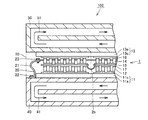
- FIG. 4 is an exploded perspective view schematically showing a configuration of a high-temperature module in a P1 portion of FIGS. 2 and 3. It is a disassembled perspective view which shows schematically the structure of the periphery of the high temperature side thermoelectric conversion element of FIG. FIG.
- FIG. 10 is an enlarged view schematically showing an example of a P4 portion in FIG. 9. It is a front view which shows roughly the state which the radiant heat shielding board of the thermoelectric generator in Embodiment 1 of this invention deform
- thermoelectric generator in Embodiment 3 of this invention. It is sectional drawing which shows schematically the structure of the thermoelectric generator in Embodiment 4 of this invention. It is a top view which shows roughly the structure of the module for low temperature in Embodiment 5 of this invention. It is a top view which shows roughly the structure of the module for high temperature in Embodiment 5 of this invention.
- Embodiment 1 First, the configuration of the thermoelectric generator in Embodiment 1 of the present invention will be described.
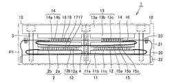
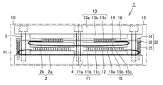
- the thermoelectric generator 1 has a plurality of thermoelectric modules 10.
- the plurality of thermoelectric modules 10 are for converting thermal energy into electrical energy.
- the plurality of thermoelectric modules 10 are electrically connected to each other by the wiring 2.
- the wiring 2 has a low temperature side wiring 2a and a high temperature side wiring 2b.
- the plurality of thermoelectric modules 10 are supported by screws 3 and columns 4.
- Each of the plurality of thermoelectric modules 10 includes a low temperature side wiring 2a, a high temperature side wiring 2b, a low temperature side member 11, a plurality of low temperature side thermoelectric conversion elements 12, a high temperature side member 13, and a plurality of high temperature side thermoelectric conversion elements. 14, an insulating member 15, a radiant heat blocking plate 16, a low temperature side electrode 17, a high temperature side electrode 18, a thermal circuit member 20, a screw 22, and a bolt 23.
- the low-temperature side thermoelectric conversion element 12 and the like are shown in a simplified manner for easy viewing.
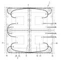
- the low temperature side member 11 supports the low temperature side plate 11 a that supports the thermoelectric module 10, the low temperature side heat equalizing plate 11 b that is made of an insulating material and uniformizes the heat from the low temperature side plate 11 a, and the low temperature side thermoelectric conversion element 12. And a low temperature side substrate 11c.
- the plurality of low temperature side thermoelectric conversion elements 12 are arranged on the low temperature side member 11 side.
- the plurality of low temperature side thermoelectric conversion elements 12 are made of a BiTe-based material.
- the plurality of low temperature side thermoelectric conversion elements 12 includes a p-type thermoelectric semiconductor element 12a and an n-type thermoelectric semiconductor element 12b that are adjacent to each other.
- the high temperature side member 13 is disposed so as to face the low temperature side member 11.
- the high temperature side member 13 supports a high temperature side plate 13 a that supports the thermoelectric module 10, a high temperature side temperature equalizing plate 13 b that is made of an insulating material and uniformizes heat from the high temperature side plate 13 a, and a high temperature side thermoelectric conversion element 14. And a high temperature side substrate 13c.
- the plurality of high temperature side thermoelectric conversion elements 14 are made of a material different from the BiTe material disposed on the high temperature side member 13 side.
- the high temperature side thermoelectric conversion element 14 preferably includes one or more materials selected from the group consisting of MgSi-based materials, SiGe-based materials, CoSb-based materials, and PbTe-based materials.
- the plurality of high temperature side thermoelectric conversion elements 14 includes a p-type thermoelectric semiconductor element 14a and an n-type thermoelectric semiconductor element 14b adjacent to each other.
- the insulating member 15 is sandwiched between the low temperature side thermoelectric conversion element 12 and the high temperature side thermoelectric conversion element 14.
- the insulating member 15 includes a central heat equalizing plate 15a, a low temperature side insulating substrate 15b, and a high temperature side insulating substrate 15c.
- the radiant heat shielding plate 16 is disposed between the insulating member 15 and the high temperature side member 13.
- the radiant heat blocking plate 16 is disposed closer to the high temperature side member 13 than the low temperature side wiring 2a and the high temperature side wiring 2b.
- the radiant heat blocking plate 16 is disposed between the low temperature side wiring 2 a and the high temperature side wiring 2 b and the high temperature side member 13.
- the low temperature side electrode 17 electrically connects a plurality of low temperature side thermoelectric conversion elements 12 in series.
- the low temperature side wiring 2 a is electrically connected to the low temperature side electrode 17.
- the high temperature side electrode 18 electrically connects a plurality of high temperature side thermoelectric conversion elements 14 in series.
- the high temperature side electrode 2 is electrically connected to the high temperature side electrode 18.
- the thermal circuit member 20 connects the radiant heat blocking plate 16 to the low temperature side member 11.
- the thermal circuit member 20 has a spring member 21.
- the thermal circuit member 20 has a flexible structure by the spring member 21.
- the thermal circuit member 20 is attached to the low temperature side member 11 with screws 22, and is attached to the radiant heat shield plate 16 with bolts 23.
- the low temperature side wiring 2a electrically connects the low temperature side electrodes 17 of the plurality of thermoelectric modules 10 to each other.
- the high temperature side wiring 2 b electrically connects the high temperature side electrodes 18 of the plurality of thermoelectric modules 10.
- the low temperature side thermoelectric conversion element 12 and the high temperature side thermoelectric conversion element 14 are illustrated in a simplified manner, and the low temperature side wiring 2 a and the high temperature side wiring 2 b are indicated by solid lines.
- the low temperature side thermoelectric conversion element 12 and the high temperature side thermoelectric conversion element 14 of each thermoelectric module 10 of the plurality of thermoelectric modules 10 are electrically connected in series with each other. 4 and 5, the low temperature side thermoelectric conversion element 12 and the high temperature side thermoelectric conversion element 14 are shown by solid lines for the sake of clarity.
- thermoelectric modules 10 the plus side terminal of the low temperature side electrode 17 of each thermoelectric module 10 and the minus side terminal of the high temperature side electrode 18 of each thermoelectric module 10 are electrically connected to each other. Thereby, the low temperature side thermoelectric conversion elements 12 of each thermoelectric module 10 are electrically connected in series with each other. Then, the low temperature side wiring 2a electrically connected to the plus side terminal of the low temperature side electrode 17 of one thermoelectric module 10 and the minus side terminal of the low temperature side electrode 17 of another thermoelectric module 10 were electrically connected. The low temperature side wiring 2 a is drawn to the outside of the thermoelectric generator 1.
- the high temperature side thermoelectric conversion elements 14 of each thermoelectric module 10 are electrically connected in series with each other. That is, in the plurality of thermoelectric modules 10, the plus side terminal of the high temperature side electrode 18 of each thermoelectric module 10 and the minus side terminal of the high temperature side electrode 18 of each thermoelectric module 10 are electrically connected to each other. Then, the low temperature side wiring 2a electrically connected to the plus side terminal of the high temperature side electrode 18 of one thermoelectric module 10 and the minus side terminal of the high temperature side electrode 18 of another thermoelectric module 10 were electrically connected. The low temperature side wiring 2 a is drawn to the outside of the thermoelectric generator 1.
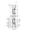
- the low temperature module of the thermoelectric module 10 includes a p-type thermoelectric semiconductor element 12a and an n-type thermoelectric semiconductor element made of BiTe material between the low temperature side substrate 11c and the low temperature side insulating substrate 15b. 12b are alternately joined in series so as to be electrically connected in series.
- the low temperature side substrate 11c and the low temperature side insulating substrate 15b are made of alumina, aluminum nitride, or the like, for example.
- the low temperature side electrode 17 is disposed via the thermal conductive grease 30.
- a pair of p-type thermoelectric semiconductor elements 12 a and n-type thermoelectric semiconductor elements 12 b are mounted on each of the independent low-temperature side electrodes 17 via solder materials 31.
- a similar low temperature side electrode 17 is also disposed on the lower surface of the low temperature side insulating substrate 15b via the heat conductive grease 30.
- the position of the low temperature side electrode 17 of the low temperature side insulating substrate 15b is shifted relative to the low temperature side electrode 17 of the low temperature side substrate 11c.
- the plurality of p-type thermoelectric semiconductor elements 12a and n bonded to each other through the solder material 31 between the plurality of low temperature side electrodes 17 of the low temperature side insulating substrate 15b and the plurality of low temperature side electrodes 17 of the low temperature side substrate 11c.
- the type thermoelectric semiconductor elements 12b are electrically connected in series alternately.
- one low temperature side wiring 2a is attached to the low temperature side electrode 17 on which only one p-type thermoelectric semiconductor element 12a is mounted by a solder material. It has been.
- Each of the low temperature side substrate 11c and the low temperature side insulating substrate 15b has, for example, a length D1 and a width D2 of 50 mm.
- the p-type thermoelectric semiconductor element 12a and the n-type thermoelectric semiconductor element 12b each have a length D3 and a width D4 of, for example, 1.95 mm.
- the low temperature module of the thermoelectric module 10 has a height of 4.2 mm, for example.
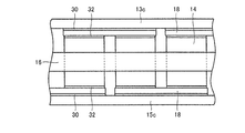
- the high temperature module of thermoelectric module 10 includes p-type thermoelectric semiconductor elements 14a and n made of a material different from BiTe-based material between high temperature side substrate 13c and high temperature side insulating substrate 15c.
- the type thermoelectric semiconductor elements 14b are joined and alternately connected in series.
- the high temperature side substrate 13c and the high temperature side insulating substrate 15c are made of alumina, aluminum nitride, or the like, for example.
- the high temperature side electrode 18 is disposed via the heat conductive grease 30.
- a pair of p-type thermoelectric semiconductor elements 14 a and n-type thermoelectric semiconductor elements 14 b are mounted on each of the independent high temperature side electrodes 18 via a brazing material 32.
- a similar high temperature side electrode 18 is also disposed on the lower surface of the high temperature side insulating substrate 15 c via the heat conductive grease 30.
- the high temperature side electrode 18 of the high temperature side insulating substrate 15c is relatively displaced from the high temperature side electrode 18 of the high temperature side substrate 13c.
- a plurality of p-type thermoelectric semiconductor elements 14a and n bonded via a brazing material 32 between the plurality of high temperature side electrodes 18 of the high temperature side insulating substrate 15c and the plurality of high temperature side electrodes 18 of the high temperature side substrate 13c.
- the type thermoelectric semiconductor elements 14b are alternately electrically connected in series.
- thermoelectric module 10 On the high temperature side substrate 13c, in order to supply electric power from the thermoelectric module 10, one high temperature side wiring 2b is attached to the high temperature side electrode 18 on which only one p-type thermoelectric semiconductor element 14a is mounted with a brazing material. It has been.
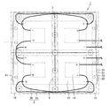
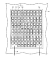
- a radiant heat shielding plate 16 is disposed between the high temperature side substrate 13c and the high temperature side insulating substrate 15c.
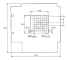
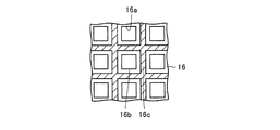
- the radiant heat shield plate 16 has a plurality of through holes 16a.
- the radiant heat blocking plate 16 has a grid-like frame formed by a plurality of through holes 16a.
- a p-type thermoelectric semiconductor element 14a and an n-type thermoelectric semiconductor element 14b are inserted into each of the plurality of through holes 16a.
- Each of the high temperature side substrate 13c and the high temperature side insulating substrate 15c has, for example, a length D11 and a width D12 of 25 mm.
- the p-type thermoelectric semiconductor element 12a and the n-type thermoelectric semiconductor element 12b each have a length D13 and a width D14 of 2.15 mm, for example.
- the radiant heat shield plate 16 has, for example, a length D17 of 69.5 mm and a width D18 of 70.0 mm.
- Each of the plurality of through holes 16a of the radiant heat shield plate 16 has a length D15 and a width D16 of 2.35 mm, for example.
- the high temperature module of the thermoelectric module 10 has a height of 4.2 mm, for example.
- the radiant heat shield plate 16 may have an insulating substrate 16b and a covering portion 16c.
- the covering portion 16c covers at least a part of the surface of the insulating substrate 16b on the high temperature side member 13 side.
- the covering portion 16c is formed between the plurality of through holes 16a, and is not formed in the through holes 16a.
- the covering portion 16c is formed, for example, by painting or plating with a high heat reflectance.
- As a material of the covering portion 16c Ag (silver), Au (gold), Cr (chromium), Ni (nickel), Pt (platinum), Sn (tin), aluminum oxide, and the like are preferable.
- thermoelectric power generation apparatus 1 of the present embodiment low temperature heat is applied to the low temperature side member 11 of the thermoelectric module 10 and high temperature heat is applied to the high temperature side member 13, whereby the low temperature side thermoelectric conversion element 12 and the high temperature side.
- An electromotive force is generated in each of the thermoelectric conversion elements 14, and a current flows through each of the low temperature side wiring 2a and the high temperature side wiring 2b. That is, electric power is taken out by the temperature difference between the high temperature side and the low temperature side of the thermoelectric module 10.
- the high temperature side is greatly extended by heat than the low temperature side.
- the high temperature side is more thermally deformed than the low temperature side.
- the high temperature side member 13 extends larger than the low temperature side member 11.
- the radiant heat blocking plate 16 also extends larger than the low temperature side member 11. Therefore, the radiant heat shielding plate 16 is deformed into a convex shape toward the high temperature side member 13.
- the thermal circuit member 20 attached to the radiant heat shield plate 16 is elastically deformed by the spring member 21.
- the spring member 21 of the thermal circuit member 20 is deformed to the low temperature side member 11 side in accordance with the thermal deformation of the radiant heat blocking plate 16. Thereby, the thermal stress which arises in the thermal circuit member 20 is reduced.
- thermoelectric module 10 of the present embodiment the insulating member 15 is sandwiched between the plurality of low-temperature side thermoelectric conversion elements 12 made of BiTe-based material and the plurality of high-temperature side thermoelectric conversion elements 14 made of a material different from the BiTe-based material. It is. And the radiant heat shielding board 16 is arrange
- the radiant heat blocking plate 16 blocks the radiant heat from the high temperature side member 13 so that the high temperature side. Burnout of the wiring 2b can be suppressed.
- thermoelectric module 10 includes the thermal circuit member 20 that connects the radiant heat shield plate 16 to the low temperature side member 11, the heat of the radiant heat shield plate 16 is transmitted to the low temperature side member 11 via the thermal circuit member 20. By doing so, the temperature rise of the radiant heat shielding plate 16 can be suppressed. For this reason, burning of the high temperature side wiring 2b due to radiant heat from the radiant heat blocking plate 16 can be suppressed.
- the thermal circuit member 20 has the spring member 21
- the thermal stress generated in the thermal circuit member 20 due to thermal deformation of the radiant heat shield plate 16 can be suppressed by elastically deforming the spring member 21. For this reason, the failure of the thermal circuit member 20 can be suppressed.
- the low temperature side member 11 has the low temperature side plate 11a connected to the thermal circuit member 20, the heat of the radiant heat shielding plate 16 is transmitted to the low temperature side plate 11a via the thermal circuit member 20, thereby radiant heat.
- the temperature rise of the blocking plate 16 can be suppressed.
- the low temperature side member 11 has the low temperature side heat equalizing plate 11b sandwiched between the plurality of low temperature side thermoelectric conversion elements 12 and the low temperature side plate 11a, the low temperature side heat equalizing plate 11b causes the low temperature side plate to be cooled.
- the heat distribution from 11a can be made uniform.
- the radiant heat shield plate 16 includes the insulating substrate 16b and the covering portion 16c that covers at least a part of the surface of the insulating substrate 16b on the high temperature side member 13 side, the high temperature side thermoelectric conversion element is formed by the insulating substrate 16b. 14 can be secured, and the radiant heat from the high temperature side member 13 can be reflected by the covering portion 16c.
- the high temperature side thermoelectric conversion element 14 is one or more selected from the group consisting of MgSi (magnesium silicon) -based materials, SiGe (silicon germanium) -based materials, CoSb (cobalt antimony) -based materials, and PbTe (lead tellurium) -based materials. Contains material. Thereby, thermoelectric conversion efficiency can be improved by being used in the temperature range in which each has high thermoelectric conversion efficiency.
- the low temperature side thermoelectric conversion element is attached to the low temperature side electrode with a solder material, and the high temperature side thermoelectric conversion element is attached to the high temperature side electrode with a brazing material.
- the low temperature side thermoelectric conversion element 12 can be fixed to the low temperature side electrode 17 by the solder material 31, and the high temperature side thermoelectric conversion element 14 can be reliably fixed to the high temperature side electrode 18 by the brazing material 32.
- the thermoelectric generator 1 of this embodiment includes a plurality of thermoelectric modules 10.
- the low temperature side wiring 2a electrically connects the low temperature side electrodes 17 of the plurality of thermoelectric modules 10, and the high temperature side wiring 2b electrically connects the high temperature side electrodes 18 of the plurality of thermoelectric modules 10. is doing.
- the thermoelectric power generation amount of the thermoelectric generator 1 can be increased by providing a plurality of thermoelectric modules 10.
- electrically connecting the low temperature side electrodes 17 and the high temperature side electrodes 18 of the plurality of thermoelectric modules 10 it is possible to use voltages suitable for the low temperature side and the high temperature side, respectively.
- the configuration of the thermal circuit member 20 is different from that of the first embodiment.
- the thermal circuit member 20 includes a bolt 24 and a coil spring 25.
- the thermal circuit member 20 may have a washer 26.
- the bolt 24 is inserted into the through hole of the radiant heat shield plate 16 and the washer 26 disposed on the lower surface of the radiant heat shield plate 16 and the washer 26 disposed on the upper surface of the low temperature side plate 11a.
- the bolt 24 is fixed to the low temperature side plate 11a by screwing the tip of the bolt 24 into the low temperature side plate 11a.
- the coil spring 25 is disposed between a washer 26 disposed on the lower surface of the radiant heat shield plate 16 and a washer 26 disposed on the upper surface of the low temperature side plate 11a.
- thermoelectric module 10 of the present embodiment low temperature heat is applied to the low temperature side member 11, and high temperature heat is applied to the high temperature side member 13, so that the radiant heat shield plate 16 is convex toward the high temperature side member 13. Transforms into At this time, the coil spring 25 is elastically deformed so as to contract along the bolt 24 in accordance with the thermal deformation of the radiant heat blocking plate 16. Thereby, the thermal stress which arises in the thermal circuit member 20 can be suppressed. For this reason, the failure of the thermal circuit member 20 can be suppressed.
- thermoelectric generator 100 includes thermoelectric generator 1, low-temperature heat medium member 40, and high-temperature heat medium member 50.
- the low temperature heat medium member 40 is attached to the low temperature side member 11 of the thermoelectric generator 1.
- the low-temperature heat medium member 40 is attached to the low-temperature side plate 11a.
- a low-temperature heat medium 41 circulates inside the low-temperature heat medium member 40.
- the low-temperature heat medium 41 for example, water vapor can be applied.
- the temperature of the low-temperature heat medium 41 is, for example, 140 ° C. or higher and 170 ° C. or lower.
- the high temperature heat medium member 50 is attached to the high temperature side member 13 of the thermoelectric generator 1.
- the high temperature heat medium member 50 is attached to the high temperature side plate 13a.
- a high temperature heat medium 51 circulates inside the high temperature heat medium member 50.
- a molten salt can be applied as the high-temperature heating medium 51.
- the temperature of the high-temperature heat medium 51 is, for example, 550 ° C. or higher.
- the temperature of the insulating member 15 is about 280 degreeC, for example.
- the heat circuit member 20 is attached to the low-temperature heat medium member 40.
- the thermal circuit member 20 may be attached to the low temperature side plate 11a.
- the high temperature side wiring 2b penetrates each insulating member 15 of the plurality of thermoelectric modules 10 and electrically connects the high temperature side electrodes 18 of the plurality of thermoelectric modules 10 across the low temperature side member 11 side from the insulating member 15. Connected.
- the high temperature side wiring 2 b penetrates the insulating member 15 and is disposed closer to the low temperature side member 11 than the insulating member 15.
- thermoelectric generator 100 of the present embodiment is attached to the low temperature side member 11 of the thermoelectric power generation device 1, and the low temperature heat medium member 40 through which the low temperature heat medium 41 circulates, and the high temperature side member 13 of the thermoelectric power generation device 1. And a high temperature heat medium member 50 in which the high temperature heat medium 51 circulates. Thereby, thermoelectric power generation can be performed by the thermoelectric power generation apparatus 1 by the heat supplied by the low temperature heat medium member 40 and the high temperature heat medium member 50.
- the high temperature side wiring 2 b penetrates the insulating member 15 and is disposed closer to the low temperature side member 11 than the insulating member 15. Thereby, the high temperature side wiring 2b can be arrange
- thermoelectric generator 100 Referring to FIG. 21, the thermoelectric generator 100 according to the fourth embodiment of the present invention includes a thermoelectric generator 1, a low temperature heat medium member 40, a high temperature heat medium member 50, a housing 60, a vacuum pump 62, And a valve 63.
- thermoelectric generator 1, the low-temperature heat medium member 40, and the high-temperature heat medium member 50 are surrounded by the housing 60.
- the thermoelectric generator 1, the low-temperature heat medium member 40, and the high-temperature heat medium member 50 are accommodated in the internal space 61 of the housing 60.
- the internal space 61 of the housing 60 is evacuated by a vacuum pump 62 through a valve 63. Thereby, the internal space 61 of the housing 60 is vacuum-sealed. That is, the pressure in the internal space 61 of the housing 60 is lower than atmospheric pressure.
- the low temperature side pipe 42 for supplying the low temperature heat medium 41 to the low temperature heat medium member 40 is drawn out from the internal space 61 of the housing 60 to the outside.
- the low-temperature heat medium 41 is circulated inside the low-temperature heat medium member 40 by a supply device for the low-temperature heat medium 41 (not shown).
- a high temperature side pipe 52 that supplies the high temperature heat medium 51 to the high temperature heat medium member 50 is drawn out from the internal space 61 of the housing 60 to the outside.
- the high temperature heat medium 51 is circulated inside the high temperature heat medium member 50 by a supply device for the high temperature heat medium 51 (not shown).
- the high temperature side wiring 2b is also drawn out from the internal space 61 of the housing 60 to the outside.
- the low temperature side pipe 42, the high temperature side pipe 52 and the wiring 2 are drawn out from the internal space 61 of the housing 60, but the internal space 61 is kept in a vacuum-sealed state.
- thermoelectric generator 100 of the present embodiment the internal space 61 of the casing 60 surrounding the thermoelectric generator 1, the low temperature heat medium member 40, and the high temperature heat medium member 50 is hermetically sealed. Thereby, it can suppress that the high temperature side thermoelectric conversion element 14 and the low temperature side thermoelectric conversion element 12 are oxidized, and thermoelectric conversion efficiency falls.
- thermoelectric semiconductor elements are electrically connected in parallel.
- the p type thermoelectric semiconductor element 12a is sandwiched between the low temperature side substrate 11c and the low temperature side insulating substrate (not shown) by the low temperature side electrode 17.
- the low temperature side wiring 2a is arranged.
- the low temperature side insulating substrate or the like is not shown, and the low temperature side electrode 17 on the low temperature side insulating substrate side is shown by a broken line.
- Two p-type thermoelectric semiconductor elements 12 a and low-temperature side wiring 2 a are arranged on one end of the low-temperature side electrode 17, and two n-type thermoelectric semiconductor elements 12 b and low-temperature on the other end of the low-temperature side electrode 17.
- Side wiring 2a is arranged. Between the one end portion and the other end portion of the low temperature side electrode 17, the central portion of the low temperature side electrode 17 is disposed. The central portion of the low temperature side electrode 17 is configured independently, and a pair of p-type thermoelectric semiconductor element 12a and n-type thermoelectric semiconductor element 12b is mounted on each of the low temperature side electrodes 17.
- the two p-type thermoelectric semiconductor elements 12a mounted on one end of the low-temperature side electrode 17 are respectively the n-type thermoelectric semiconductor element 12b arranged at the center of another low-temperature side electrode 17 and the low-temperature indicated by a broken line. They are connected by side electrodes 17.
- two n-type thermoelectric semiconductor elements 12b mounted on the other end of the low-temperature side electrode 17 are respectively indicated by broken lines with a p-type thermoelectric semiconductor element 12a disposed at the center of another low-temperature side electrode 17.
- the low temperature side electrode 17 is connected.
- thermoelectric semiconductor element 12a disposed outside the one end portion of the low temperature side electrode 17, the n type thermoelectric semiconductor element 12b disposed outside the other end portion of the low temperature side electrode 17, and the low temperature side electrode.
- a p-type thermoelectric semiconductor element 12 a and an n-type thermoelectric semiconductor element 12 b arranged at the center of 17 are electrically connected by a low temperature side electrode 17. In this way, an outer circuit is formed.
- the p-type thermoelectric semiconductor element 12 a disposed inside one end of the low-temperature side electrode 17, the n-type thermoelectric semiconductor element 12 b disposed inside the other end of the low-temperature side electrode 17, and the low-temperature side electrode 17 The p-type thermoelectric semiconductor element 12a and the n-type thermoelectric semiconductor element 12b disposed in the central part of each are electrically connected. In this way, an inner circuit is formed.
- the outer circuit and the inner circuit are electrically connected in parallel at one end and the other end of the low temperature side electrode 17. That is, the low temperature side electrode 17 electrically connects a plurality of p-type thermoelectric semiconductor elements 12a and n-type thermoelectric semiconductor elements 12b in parallel.
- the p type thermoelectric semiconductor element 14a is sandwiched between the high temperature side insulating substrate 13c and the high temperature side substrate (not shown) by the high temperature side electrode 18.
- a high temperature side wiring 2b is arranged.
- the high temperature side substrate or the like is not shown, and the high temperature side electrode 18 on the high temperature side substrate side is shown by a broken line.
- Two p-type thermoelectric semiconductor elements 14 a and high-temperature side wiring 2 b are arranged on one end of the high-temperature side electrode 18, and two n-type thermoelectric semiconductor elements 14 b and high-temperature on the other end of the high-temperature side electrode 18.
- Side wiring 2b is arranged.
- a central portion of the high temperature side electrode 18 is disposed between one end and the other end of the high temperature side electrode 18.
- the central portion of the high temperature side electrode 18 is independently configured, and a pair of p-type thermoelectric semiconductor element 14a and n-type thermoelectric semiconductor element 14b is mounted on each of the high temperature side electrodes 18.
- the radiant heat blocking plate 16 is inserted into the plurality of through holes 16a.
- Two p-type thermoelectric semiconductor elements 14a mounted on one end of the high-temperature side electrode 18 are respectively connected to an n-type thermoelectric semiconductor element 14b arranged at the center of another high-temperature side electrode 18 and a high temperature indicated by a broken line. They are connected by side electrodes 18.
- two n-type thermoelectric semiconductor elements 14b mounted on the other end of the high-temperature side electrode 18 are each indicated by a broken line of the p-type thermoelectric semiconductor element 14a disposed at the center of another high-temperature side electrode 18. They are connected by a high temperature side electrode 18.
- thermoelectric semiconductor element 14a disposed outside the one end of the high temperature side electrode 18, the n type thermoelectric semiconductor element 14b disposed outside the other end of the high temperature side electrode 18, and the low temperature side electrode
- a p-type thermoelectric semiconductor element 14 a and an n-type thermoelectric semiconductor element 14 b arranged at the center of 18 are electrically connected by a high temperature side electrode 18. In this way, an outer circuit is formed.
- the p-type thermoelectric semiconductor element 14a and the n-type thermoelectric semiconductor element 14b disposed in the central part of are electrically connected. In this way, an inner circuit is formed.
- the outer circuit and the inner circuit are electrically connected in parallel at one end and the other end of the high temperature side electrode 18. That is, the high temperature side electrode 18 electrically connects a plurality of p-type thermoelectric semiconductor elements 14a and n-type thermoelectric semiconductor elements 14b in parallel.
- the logarithms of the p-type thermoelectric semiconductor element 14a and the n-type thermoelectric semiconductor element 14b of the external circuit and the internal circuit that are arranged in parallel are made the same.
- the generated voltage of the external circuit and the internal circuit are aligned.
- the parallel number of the external circuit and the internal circuit in the thermoelectric module is two, but the generated voltage of the thermoelectric module may be defined to match the power module that adjusts the output, and the parallel number is two. Not necessarily.
- thermoelectric module 10 of the thermoelectric generator 1 may not be provided with a soaking plate.
- thermoelectric module having a low-temperature side and a high-temperature side thermoelectric conversion element, and a thermoelectric power generation apparatus and a thermoelectric generator including the thermoelectric module.
- thermoelectric conversion element 15 Insulation member, 15a Central soaking plate, 15b Low temperature side insulating substrate, 15c High temperature side insulation Substrate, 16 radiant heat blocking plate, 16a through hole, 16b insulating substrate, 16c coating, 17 low temperature side electrode, 18 high temperature side electrode, 20 thermal circuit member, 21 spring member, 24 bolt, 25 coil spring, 31 solder material, 32 solder Material, 40 low temperature heating medium member, 41 low temperature heating medium, 50 high temperature heating medium member, 51 high temperature heating medium, 6 Casing, 61 the internal space, 100 thermoelectric
Abstract
Description
(実施の形態1)
まず本発明の実施の形態1における熱電発電装置の構成について説明する。
図6~図8を参照して、熱電モジュール10の低温用モジュールは、低温側基板11cと低温側絶縁基板15bとの間にBiTe系材料からなるp型熱電半導体素子12aとn型熱電半導体素子12bとを交互に電気的に直列接続するように接合して構成されている。低温側基板11cと低温側絶縁基板15bとは、たとえばアルミナおよび窒化アルミニウムなどで形成されている。
本実施の形態の熱電モジュール10によれば、BiTe系材料からなる複数の低温側熱電変換素子12とBiTe系材料とは異なる材料からなる複数の高温側熱電変換素子14とに絶縁部材15が挟まれている。そして、輻射熱遮断板16は、絶縁部材15と高温側部材13との間に配置されており、低温側配線2aおよび高温側配線2bよりも高温側部材13側に配置されている。これにより、複数の低温側熱電変換素子12および複数の高温側熱電変換素子14を有するカスケード型の熱電モジュール10において、輻射熱遮断板16によって高温側部材13からの輻射熱を遮断することにより、高温側配線2bの焼損を抑制することができる。
本発明の実施の形態2では、実施の形態1と対比して熱回路部材20の構成が異なっている。図16~図19を参照して、本実施の形態の熱電発電装置1では、熱回路部材20はボルト24と、コイルバネ25とを有している。また熱回路部材20はワッシャ26を有していてもよい。本実施の形態ではボルト24は輻射熱遮断板16の貫通孔ならびに輻射熱遮断板16の下面上に配置されたワッシャ26および低温側プレート11aの上面上に配置されたワッシャ26に挿入されている。
図20を参照して、本発明の実施の形態3の熱電発電器100は、熱電発電装置1と、低温熱媒部材40と、高温熱媒部材50とを有している。低温熱媒部材40は熱電発電装置1の低温側部材11に取付けられている。本実施の形態では、低温熱媒部材40は低温側プレート11aに取付けられている。低温熱媒部材40の内部を低温熱媒41が循環している。低温熱媒41としてはたとえば水蒸気が適用され得る。低温熱媒41の温度はたとえば140℃以上170℃以下である。
図21を参照して、本発明の実施の形態4の熱電発電器100は、熱電発電装置1と、低温熱媒部材40と、高温熱媒部材50と、筺体60と、真空ポンプ62と、バルブ63とを有している。
本発明の実施の形態5では、実施の形態1と対比して複数の熱電半導体素子が電気的に並列に接続されている点で異なっている。
今回開示された実施の形態はすべての点で例示であって制限的なものではないと考えられるべきである。本発明の範囲は上記した説明ではなくて請求の範囲によって示され、請求の範囲と均等の意味および範囲内でのすべての変更が含まれることを意図される。
Claims (12)
- 低温側部材と、
前記低温側部材側に配置されたBiTe系材料からなる複数の低温側熱電変換素子と、
前記複数の低温側熱電変換素子を電気的に直列および並列のいずれかに接続する低温側電極と、
前記低温側電極に電気的に接続された低温側配線と、
前記低温側部材と対向する高温側部材と、
前記高温側部材側に配置された前記BiTe系材料とは異なる材料からなる複数の高温側熱電変換素子と、
前記複数の高温側熱電変換素子を電気的に直列および並列のいずれかに接続する高温側電極と、
前記高温側電極に電気的に接続された高温側配線と、
前記低温側熱電変換素子と前記高温側熱電変換素子とに挟まれた絶縁部材と、
前記絶縁部材と前記高温側部材との間に配置された輻射熱遮断板とを備え、
前記輻射熱遮断板は、前記低温側配線および前記高温側配線よりも前記高温側部材側に配置されている、熱電モジュール。 - 前記輻射熱遮断板を前記低温側部材に接続する熱回路部材をさらに備えた、請求項1に記載の熱電モジュール。
- 前記熱回路部材はバネ部材を含む、請求項2に記載の熱電モジュール。
- 前記低温側部材は前記熱回路部材に接続される低温側プレートを含む、請求項2または3に記載の熱電モジュール。
- 前記低温側部材は、絶縁材料からなり、前記複数の低温側熱電変換素子と前記低温側プレートとの間に挟まれた低温側均熱板を含む、請求項4に記載の熱電モジュール。
- 前記輻射熱遮断板は、
絶縁基板と、
前記絶縁基板の少なくとも前記高温側部材側の表面の一部を被覆する被覆部とを含む、請求項1~5のいずれかに記載の熱電モジュール。 - 前記高温側熱電変換素子は、MgSi系材料、SiGe系材料、CoSb系材料およびPbTe系材料よりなる群から選ばれる1種以上の材料を含む、請求項1~6のいずれかに記載の熱電モジュール。
- 前記低温側熱電変換素子は前記低温側電極に半田材によって取り付けられており、
前記高温側熱電変換素子は前記高温側電極にロウ材によって取り付けられている、請求項1~7のいずれかに記載の熱電モジュール。 - 前記高温側配線は、前記絶縁部材を貫通し、前記絶縁部材よりも前記低温側部材側に配設されている、請求項1~8のいずれかに記載の熱電モジュール。
- 請求項1~9のいずれかに記載の熱電モジュールを複数備え、
前記低温側配線は前記複数の熱電モジュールの各々の前記低温側電極同士を電気的に接続しており、
前記高温側配線は前記複数の熱電モジュールの各々の前記高温側電極同士を電気的に接続している、熱電発電装置。 - 請求項10に記載の熱電発電装置と、
前記熱電発電装置の前記低温側部材に取り付けられ、かつ低温熱媒が内部を循環する低温熱媒部材と、
前記熱電発電装置の前記高温側部材に取り付けられ、かつ高温熱媒が内部を循環する高温熱媒部材とをさらに備えた、熱電発電器。 - 前記熱電発電装置と、前記低温熱媒部材と、前記高温熱媒部材とを取り囲む筺体をさらに備え、
前記筺体の内部空間は真空密閉されている、請求項11に記載の熱電発電器。
Priority Applications (3)
| Application Number | Priority Date | Filing Date | Title |
|---|---|---|---|
| JP2014502100A JP5815112B2 (ja) | 2012-02-27 | 2013-02-07 | 熱電モジュール、熱電発電装置および熱電発電器 |
| US14/379,626 US9793462B2 (en) | 2012-02-27 | 2013-02-07 | Thermoelectric module, thermoelectric power generating apparatus, and thermoelectric generator |
| CN201380010047.XA CN104115294B (zh) | 2012-02-27 | 2013-02-07 | 热电模块、热电发电装置以及热电发电器 |
Applications Claiming Priority (2)
| Application Number | Priority Date | Filing Date | Title |
|---|---|---|---|
| JP2012040385 | 2012-02-27 | ||
| JP2012-040385 | 2012-02-27 |
Publications (1)
| Publication Number | Publication Date |
|---|---|
| WO2013129057A1 true WO2013129057A1 (ja) | 2013-09-06 |
Family
ID=49082260
Family Applications (1)
| Application Number | Title | Priority Date | Filing Date |
|---|---|---|---|
| PCT/JP2013/052822 WO2013129057A1 (ja) | 2012-02-27 | 2013-02-07 | 熱電モジュール、熱電発電装置および熱電発電器 |
Country Status (4)
| Country | Link |
|---|---|
| US (1) | US9793462B2 (ja) |
| JP (1) | JP5815112B2 (ja) |
| CN (1) | CN104115294B (ja) |
| WO (1) | WO2013129057A1 (ja) |
Cited By (3)
| Publication number | Priority date | Publication date | Assignee | Title |
|---|---|---|---|---|
| JP2017098327A (ja) * | 2015-11-19 | 2017-06-01 | 昭和電線ケーブルシステム株式会社 | 積層型熱電変換モジュール及び熱電変換装置 |
| KR20180022427A (ko) * | 2016-08-24 | 2018-03-06 | 주식회사 엘지화학 | 열전 모듈 패키징 장치 |
| KR101860600B1 (ko) * | 2014-11-05 | 2018-05-23 | 국방과학연구소 | 열전소자를 이용한 폐열 회수형 열전 발전장치 |
Families Citing this family (11)
| Publication number | Priority date | Publication date | Assignee | Title |
|---|---|---|---|---|
| USD816198S1 (en) | 2015-01-28 | 2018-04-24 | Phononic, Inc. | Thermoelectric heat pump |
| WO2016134285A1 (en) * | 2015-02-19 | 2016-08-25 | Novus Energy Technologies, Inc. | Large footprint, high power density thermoelectric modules for high temperature applications |
| JP6859739B2 (ja) * | 2016-02-24 | 2021-04-14 | 三菱マテリアル株式会社 | 熱電変換セル及び熱電変換モジュール |
| KR102528360B1 (ko) * | 2016-09-02 | 2023-05-03 | 엘지이노텍 주식회사 | 열전 소자 및 열전 모듈 |
| US11462669B2 (en) * | 2017-03-17 | 2022-10-04 | Sheetak, Inc. | Thermoelectric device structures |
| JP6889016B2 (ja) * | 2017-04-21 | 2021-06-18 | 株式会社Kelk | 熱電発電装置 |
| USD833588S1 (en) | 2017-10-11 | 2018-11-13 | Phononic, Inc. | Thermoelectric heat pump |
| WO2020149811A1 (en) * | 2019-01-14 | 2020-07-23 | Saydere Savas | Electrical to thermal to electrical converter (etec) |
| KR20200098391A (ko) * | 2019-02-12 | 2020-08-20 | 엘지이노텍 주식회사 | 열전모듈 |
| US20230043063A1 (en) * | 2019-12-24 | 2023-02-09 | Mitsubishi Materials Corporation | Thermoelectric conversion material, thermoelectric conversion element, and thermoelectric conversion module |
| US11892204B2 (en) | 2020-11-20 | 2024-02-06 | Sheetak, Inc. | Nested freezers for storage and transportation of covid vaccine |
Citations (7)
| Publication number | Priority date | Publication date | Assignee | Title |
|---|---|---|---|---|
| JPH0370483A (ja) * | 1989-08-04 | 1991-03-26 | Japan Atom Power Co Ltd:The | 高熱抵抗型熱電発電装置 |
| JPH1079532A (ja) * | 1996-09-04 | 1998-03-24 | Nanba Kikujiro | 熱電変換装置 |
| JP2000091649A (ja) * | 1998-09-14 | 2000-03-31 | Ngk Insulators Ltd | 熱電素子、熱電変換モジュールコア、熱電変換モジュールおよびその製造方法 |
| JP2004064015A (ja) * | 2002-07-31 | 2004-02-26 | Eco 21 Inc | 熱電変換装置の製造方法ならびに熱電変換装置 |
| JP2006165457A (ja) * | 2004-12-10 | 2006-06-22 | Ishikawajima Harima Heavy Ind Co Ltd | 熱電モジュール、熱電ユニット及び熱電モジュールの取付け方法 |
| JP2009141079A (ja) * | 2007-12-05 | 2009-06-25 | Jr Higashi Nippon Consultants Kk | 熱電素子モジュール |
| JP2012038980A (ja) * | 2010-08-09 | 2012-02-23 | Fujitsu Ltd | 熱電変換モジュールおよびその製造方法 |
Family Cites Families (14)
| Publication number | Priority date | Publication date | Assignee | Title |
|---|---|---|---|---|
| US3326726A (en) * | 1963-03-22 | 1967-06-20 | Gen Motors Corp | Thermoelectric array and method of manufacture |
| WO1997013010A1 (en) * | 1995-09-29 | 1997-04-10 | Union Material Inc. | Method of manufacturing shaped crystals by upward pressurization type liquid injection |
| JP2000244024A (ja) * | 1999-02-23 | 2000-09-08 | Matsushita Electric Works Ltd | 熱電素子モジュール |
| JP2000286469A (ja) * | 1999-03-30 | 2000-10-13 | Nissan Motor Co Ltd | 熱電発電装置 |
| US6759586B2 (en) * | 2001-03-26 | 2004-07-06 | Kabushiki Kaisha Toshiba | Thermoelectric module and heat exchanger |
| JP2004281451A (ja) * | 2003-03-12 | 2004-10-07 | Seiko Instruments Inc | 熱電変換素子 |
| JP4481606B2 (ja) | 2003-08-29 | 2010-06-16 | 株式会社東芝 | 熱電変換装置 |
| JP4133873B2 (ja) * | 2004-03-04 | 2008-08-13 | 株式会社デンソー | 熱電発電装置 |
| JP4622585B2 (ja) * | 2005-03-02 | 2011-02-02 | 株式会社Ihi | 熱電変換用カスケードモジュール |
| JP4832137B2 (ja) * | 2006-03-29 | 2011-12-07 | 岡野電線株式会社 | 熱電変換モジュール |
| JP2008034664A (ja) | 2006-07-29 | 2008-02-14 | Tekkusu Iijii:Kk | 熱電変換装置 |
| DE102008005694B4 (de) | 2008-01-23 | 2015-05-07 | Fraunhofer-Gesellschaft zur Förderung der angewandten Forschung e.V. | Verfahren zur Herstellung eines thermoelektrischen Bauelementes |
| DE102009009586A1 (de) * | 2009-02-19 | 2010-08-26 | Emitec Gesellschaft Für Emissionstechnologie Mbh | Thermoelektrische Vorrichtung |
| KR101680766B1 (ko) | 2010-01-14 | 2016-11-29 | 삼성전자주식회사 | 열전 소자 및 열전 소자 어레이 |
-
2013
- 2013-02-07 JP JP2014502100A patent/JP5815112B2/ja not_active Expired - Fee Related
- 2013-02-07 US US14/379,626 patent/US9793462B2/en not_active Expired - Fee Related
- 2013-02-07 WO PCT/JP2013/052822 patent/WO2013129057A1/ja active Application Filing
- 2013-02-07 CN CN201380010047.XA patent/CN104115294B/zh not_active Expired - Fee Related
Patent Citations (7)
| Publication number | Priority date | Publication date | Assignee | Title |
|---|---|---|---|---|
| JPH0370483A (ja) * | 1989-08-04 | 1991-03-26 | Japan Atom Power Co Ltd:The | 高熱抵抗型熱電発電装置 |
| JPH1079532A (ja) * | 1996-09-04 | 1998-03-24 | Nanba Kikujiro | 熱電変換装置 |
| JP2000091649A (ja) * | 1998-09-14 | 2000-03-31 | Ngk Insulators Ltd | 熱電素子、熱電変換モジュールコア、熱電変換モジュールおよびその製造方法 |
| JP2004064015A (ja) * | 2002-07-31 | 2004-02-26 | Eco 21 Inc | 熱電変換装置の製造方法ならびに熱電変換装置 |
| JP2006165457A (ja) * | 2004-12-10 | 2006-06-22 | Ishikawajima Harima Heavy Ind Co Ltd | 熱電モジュール、熱電ユニット及び熱電モジュールの取付け方法 |
| JP2009141079A (ja) * | 2007-12-05 | 2009-06-25 | Jr Higashi Nippon Consultants Kk | 熱電素子モジュール |
| JP2012038980A (ja) * | 2010-08-09 | 2012-02-23 | Fujitsu Ltd | 熱電変換モジュールおよびその製造方法 |
Cited By (4)
| Publication number | Priority date | Publication date | Assignee | Title |
|---|---|---|---|---|
| KR101860600B1 (ko) * | 2014-11-05 | 2018-05-23 | 국방과학연구소 | 열전소자를 이용한 폐열 회수형 열전 발전장치 |
| JP2017098327A (ja) * | 2015-11-19 | 2017-06-01 | 昭和電線ケーブルシステム株式会社 | 積層型熱電変換モジュール及び熱電変換装置 |
| KR20180022427A (ko) * | 2016-08-24 | 2018-03-06 | 주식회사 엘지화학 | 열전 모듈 패키징 장치 |
| KR102028017B1 (ko) * | 2016-08-24 | 2019-10-02 | 주식회사 엘지화학 | 열전 모듈 패키징 장치 |
Also Published As
| Publication number | Publication date |
|---|---|
| US9793462B2 (en) | 2017-10-17 |
| JPWO2013129057A1 (ja) | 2015-07-30 |
| JP5815112B2 (ja) | 2015-11-17 |
| CN104115294B (zh) | 2016-11-23 |
| US20150013740A1 (en) | 2015-01-15 |
| CN104115294A (zh) | 2014-10-22 |
Similar Documents
| Publication | Publication Date | Title |
|---|---|---|
| JP5815112B2 (ja) | 熱電モジュール、熱電発電装置および熱電発電器 | |
| US8841540B2 (en) | High temperature thermoelectrics | |
| JP5065077B2 (ja) | 熱電発電装置 | |
| JP2005277206A (ja) | 熱電変換装置 | |
| JP4481606B2 (ja) | 熱電変換装置 | |
| JP2008177356A (ja) | 熱電発電素子 | |
| JP4287262B2 (ja) | 熱電変換装置 | |
| KR102323978B1 (ko) | 열전 모듈 | |
| JP7052200B2 (ja) | 熱電変換モジュール | |
| KR102304603B1 (ko) | 열전모듈 | |
| EP3232483B1 (en) | Thermoelectric conversion module | |
| WO2017164217A1 (ja) | 熱電変換モジュール | |
| KR102456680B1 (ko) | 열전소자 | |
| KR102021664B1 (ko) | 다중 다열 배열식 열전 발전장치 및 그 제조방법 | |
| JP2005057124A (ja) | 熱電変換モジュール及び熱電変換装置 | |
| KR102423607B1 (ko) | 열전 모듈 | |
| JP2013247123A (ja) | 熱電変換装置 | |
| JP7281715B2 (ja) | 熱電変換モジュール | |
| JP2018125498A (ja) | 熱電変換装置 | |
| US20200028058A1 (en) | Thermoelectric conversion device | |
| US10103311B2 (en) | Flexible sink for a thermoelectric energy generation system | |
| JP2020013956A (ja) | 熱電変換装置 | |
| KR20190094039A (ko) | 열전 모듈 및 그 제조 방법 | |
| JP2017143101A (ja) | 熱電変換モジュール | |
| JP2017098514A (ja) | ペルチェ温度制御装置 |
Legal Events
| Date | Code | Title | Description |
|---|---|---|---|
| 121 | Ep: the epo has been informed by wipo that ep was designated in this application |
Ref document number: 13754820 Country of ref document: EP Kind code of ref document: A1 |
|
| ENP | Entry into the national phase |
Ref document number: 2014502100 Country of ref document: JP Kind code of ref document: A |
|
| WWE | Wipo information: entry into national phase |
Ref document number: 14379626 Country of ref document: US |
|
| NENP | Non-entry into the national phase |
Ref country code: DE |
|
| 122 | Ep: pct application non-entry in european phase |
Ref document number: 13754820 Country of ref document: EP Kind code of ref document: A1 |