WO2013122157A1 - タイヤ - Google Patents
タイヤ Download PDFInfo
- Publication number
- WO2013122157A1 WO2013122157A1 PCT/JP2013/053553 JP2013053553W WO2013122157A1 WO 2013122157 A1 WO2013122157 A1 WO 2013122157A1 JP 2013053553 W JP2013053553 W JP 2013053553W WO 2013122157 A1 WO2013122157 A1 WO 2013122157A1
- Authority
- WO
- WIPO (PCT)
- Prior art keywords
- tire
- elastomer
- gas
- polyamide
- layer
- Prior art date
Links
Images


Classifications
-
- B—PERFORMING OPERATIONS; TRANSPORTING
- B60—VEHICLES IN GENERAL
- B60C—VEHICLE TYRES; TYRE INFLATION; TYRE CHANGING; CONNECTING VALVES TO INFLATABLE ELASTIC BODIES IN GENERAL; DEVICES OR ARRANGEMENTS RELATED TO TYRES
- B60C1/00—Tyres characterised by the chemical composition or the physical arrangement or mixture of the composition
- B60C1/0008—Compositions of the inner liner
-
- B—PERFORMING OPERATIONS; TRANSPORTING
- B60—VEHICLES IN GENERAL
- B60C—VEHICLE TYRES; TYRE INFLATION; TYRE CHANGING; CONNECTING VALVES TO INFLATABLE ELASTIC BODIES IN GENERAL; DEVICES OR ARRANGEMENTS RELATED TO TYRES
- B60C1/00—Tyres characterised by the chemical composition or the physical arrangement or mixture of the composition
- B60C1/0041—Compositions of the carcass layers
-
- B—PERFORMING OPERATIONS; TRANSPORTING
- B60—VEHICLES IN GENERAL
- B60C—VEHICLE TYRES; TYRE INFLATION; TYRE CHANGING; CONNECTING VALVES TO INFLATABLE ELASTIC BODIES IN GENERAL; DEVICES OR ARRANGEMENTS RELATED TO TYRES
- B60C5/00—Inflatable pneumatic tyres or inner tubes
- B60C5/007—Inflatable pneumatic tyres or inner tubes made from other material than rubber
-
- B—PERFORMING OPERATIONS; TRANSPORTING
- B60—VEHICLES IN GENERAL
- B60C—VEHICLE TYRES; TYRE INFLATION; TYRE CHANGING; CONNECTING VALVES TO INFLATABLE ELASTIC BODIES IN GENERAL; DEVICES OR ARRANGEMENTS RELATED TO TYRES
- B60C5/00—Inflatable pneumatic tyres or inner tubes
- B60C5/01—Inflatable pneumatic tyres or inner tubes without substantial cord reinforcement, e.g. cordless tyres, cast tyres
-
- B—PERFORMING OPERATIONS; TRANSPORTING
- B60—VEHICLES IN GENERAL
- B60C—VEHICLE TYRES; TYRE INFLATION; TYRE CHANGING; CONNECTING VALVES TO INFLATABLE ELASTIC BODIES IN GENERAL; DEVICES OR ARRANGEMENTS RELATED TO TYRES
- B60C5/00—Inflatable pneumatic tyres or inner tubes
- B60C5/12—Inflatable pneumatic tyres or inner tubes without separate inflatable inserts, e.g. tubeless tyres with transverse section open to the rim
- B60C5/14—Inflatable pneumatic tyres or inner tubes without separate inflatable inserts, e.g. tubeless tyres with transverse section open to the rim with impervious liner or coating on the inner wall of the tyre
-
- C—CHEMISTRY; METALLURGY
- C08—ORGANIC MACROMOLECULAR COMPOUNDS; THEIR PREPARATION OR CHEMICAL WORKING-UP; COMPOSITIONS BASED THEREON
- C08F—MACROMOLECULAR COMPOUNDS OBTAINED BY REACTIONS ONLY INVOLVING CARBON-TO-CARBON UNSATURATED BONDS
- C08F216/00—Copolymers of compounds having one or more unsaturated aliphatic radicals, each having only one carbon-to-carbon double bond, and at least one being terminated by an alcohol, ether, aldehydo, ketonic, acetal or ketal radical
- C08F216/02—Copolymers of compounds having one or more unsaturated aliphatic radicals, each having only one carbon-to-carbon double bond, and at least one being terminated by an alcohol, ether, aldehydo, ketonic, acetal or ketal radical by an alcohol radical
- C08F216/04—Acyclic compounds
- C08F216/06—Polyvinyl alcohol ; Vinyl alcohol
-
- C—CHEMISTRY; METALLURGY
- C08—ORGANIC MACROMOLECULAR COMPOUNDS; THEIR PREPARATION OR CHEMICAL WORKING-UP; COMPOSITIONS BASED THEREON
- C08G—MACROMOLECULAR COMPOUNDS OBTAINED OTHERWISE THAN BY REACTIONS ONLY INVOLVING UNSATURATED CARBON-TO-CARBON BONDS
- C08G69/00—Macromolecular compounds obtained by reactions forming a carboxylic amide link in the main chain of the macromolecule
- C08G69/02—Polyamides derived from amino-carboxylic acids or from polyamines and polycarboxylic acids
- C08G69/08—Polyamides derived from amino-carboxylic acids or from polyamines and polycarboxylic acids derived from amino-carboxylic acids
- C08G69/14—Lactams
-
- C—CHEMISTRY; METALLURGY
- C08—ORGANIC MACROMOLECULAR COMPOUNDS; THEIR PREPARATION OR CHEMICAL WORKING-UP; COMPOSITIONS BASED THEREON
- C08G—MACROMOLECULAR COMPOUNDS OBTAINED OTHERWISE THAN BY REACTIONS ONLY INVOLVING UNSATURATED CARBON-TO-CARBON BONDS
- C08G69/00—Macromolecular compounds obtained by reactions forming a carboxylic amide link in the main chain of the macromolecule
- C08G69/02—Polyamides derived from amino-carboxylic acids or from polyamines and polycarboxylic acids
- C08G69/26—Polyamides derived from amino-carboxylic acids or from polyamines and polycarboxylic acids derived from polyamines and polycarboxylic acids
-
- C—CHEMISTRY; METALLURGY
- C08—ORGANIC MACROMOLECULAR COMPOUNDS; THEIR PREPARATION OR CHEMICAL WORKING-UP; COMPOSITIONS BASED THEREON
- C08L—COMPOSITIONS OF MACROMOLECULAR COMPOUNDS
- C08L23/00—Compositions of homopolymers or copolymers of unsaturated aliphatic hydrocarbons having only one carbon-to-carbon double bond; Compositions of derivatives of such polymers
- C08L23/02—Compositions of homopolymers or copolymers of unsaturated aliphatic hydrocarbons having only one carbon-to-carbon double bond; Compositions of derivatives of such polymers not modified by chemical after-treatment
- C08L23/16—Elastomeric ethene-propene or ethene-propene-diene copolymers, e.g. EPR and EPDM rubbers
-
- C—CHEMISTRY; METALLURGY
- C08—ORGANIC MACROMOLECULAR COMPOUNDS; THEIR PREPARATION OR CHEMICAL WORKING-UP; COMPOSITIONS BASED THEREON
- C08L—COMPOSITIONS OF MACROMOLECULAR COMPOUNDS
- C08L29/00—Compositions of homopolymers or copolymers of compounds having one or more unsaturated aliphatic radicals, each having only one carbon-to-carbon double bond, and at least one being terminated by an alcohol, ether, aldehydo, ketonic, acetal or ketal radical; Compositions of hydrolysed polymers of esters of unsaturated alcohols with saturated carboxylic acids; Compositions of derivatives of such polymers
- C08L29/02—Homopolymers or copolymers of unsaturated alcohols
- C08L29/04—Polyvinyl alcohol; Partially hydrolysed homopolymers or copolymers of esters of unsaturated alcohols with saturated carboxylic acids
-
- C—CHEMISTRY; METALLURGY
- C08—ORGANIC MACROMOLECULAR COMPOUNDS; THEIR PREPARATION OR CHEMICAL WORKING-UP; COMPOSITIONS BASED THEREON
- C08L—COMPOSITIONS OF MACROMOLECULAR COMPOUNDS
- C08L77/00—Compositions of polyamides obtained by reactions forming a carboxylic amide link in the main chain; Compositions of derivatives of such polymers
- C08L77/02—Polyamides derived from omega-amino carboxylic acids or from lactams thereof
-
- C—CHEMISTRY; METALLURGY
- C08—ORGANIC MACROMOLECULAR COMPOUNDS; THEIR PREPARATION OR CHEMICAL WORKING-UP; COMPOSITIONS BASED THEREON
- C08L—COMPOSITIONS OF MACROMOLECULAR COMPOUNDS
- C08L77/00—Compositions of polyamides obtained by reactions forming a carboxylic amide link in the main chain; Compositions of derivatives of such polymers
- C08L77/06—Polyamides derived from polyamines and polycarboxylic acids
-
- C—CHEMISTRY; METALLURGY
- C08—ORGANIC MACROMOLECULAR COMPOUNDS; THEIR PREPARATION OR CHEMICAL WORKING-UP; COMPOSITIONS BASED THEREON
- C08G—MACROMOLECULAR COMPOUNDS OBTAINED OTHERWISE THAN BY REACTIONS ONLY INVOLVING UNSATURATED CARBON-TO-CARBON BONDS
- C08G2380/00—Tyres
-
- C—CHEMISTRY; METALLURGY
- C08—ORGANIC MACROMOLECULAR COMPOUNDS; THEIR PREPARATION OR CHEMICAL WORKING-UP; COMPOSITIONS BASED THEREON
- C08L—COMPOSITIONS OF MACROMOLECULAR COMPOUNDS
- C08L2201/00—Properties
- C08L2201/14—Gas barrier composition
-
- C—CHEMISTRY; METALLURGY
- C08—ORGANIC MACROMOLECULAR COMPOUNDS; THEIR PREPARATION OR CHEMICAL WORKING-UP; COMPOSITIONS BASED THEREON
- C08L—COMPOSITIONS OF MACROMOLECULAR COMPOUNDS
- C08L2205/00—Polymer mixtures characterised by other features
- C08L2205/02—Polymer mixtures characterised by other features containing two or more polymers of the same C08L -group
-
- C—CHEMISTRY; METALLURGY
- C08—ORGANIC MACROMOLECULAR COMPOUNDS; THEIR PREPARATION OR CHEMICAL WORKING-UP; COMPOSITIONS BASED THEREON
- C08L—COMPOSITIONS OF MACROMOLECULAR COMPOUNDS
- C08L2205/00—Polymer mixtures characterised by other features
- C08L2205/03—Polymer mixtures characterised by other features containing three or more polymers in a blend
Definitions
- the present invention relates to a tire mounted on a rim, and particularly relates to a tire formed at least partially from a resin material.
- pneumatic tires made of rubber, organic fiber materials, steel members, and the like are used for vehicles such as passenger cars.
- Patent Document 1 Japanese Patent Laid-Open No. 2003-104008
- Patent Document 2 Japanese Patent Laid-Open No. 03-143701
- JP 2003-104008 A Japanese Patent Laid-Open No. 03-143701
- a tire using a thermoplastic polymer material is easier to manufacture and lower in cost than a conventional rubber tire.
- a tire using a thermoplastic polymer material is rich in flexibility and has an advantage that a light weight can be manufactured because the structure is simpler than that of a conventional rubber tire.
- a tire using a thermoplastic polymer material is rich in flexibility, there is still room for improvement in terms of gas retention characteristics against air or the like in the tire.
- IIR rubber rubber-like copolymer of isobutene and isoprene (butyl rubber)
- is used as a gas retention layer in order to improve gas retention characteristics.
- the gas retaining layer formed of IIR rubber is heavy, and is not suitable for a tire using a polymer material intended for weight reduction. Further, when a gas retaining layer formed of IIR rubber is provided on a tire using a polymer material, it is necessary to use a vulcanized adhesive in order to bond the gas retaining layer and the tire skeleton. As described above, when a vulcanized adhesive is used for bonding the gas retention layer, there are many restrictions in the manufacturing process, such as restrictions on vulcanization molding.
- the present invention has been made to solve the above-described problems, and is intended to provide a tire that is formed using a resin material, is lightweight, and has excellent retention characteristics of gas contained in a tire skeleton. is there.
- the tire of the present invention has an annular tire skeleton formed of at least a resin material and having a laminated structure, and the tire skeleton includes at least one gas retaining layer.
- 1 is a perspective view showing a partial cross section of a tire according to an embodiment of the present invention. It is sectional drawing of the bead part with which the rim
- 1 is a cross-sectional view along a tire rotation axis showing a state in which a reinforcement cord is embedded in a crown portion of a tire case of a tire according to Embodiment 1-1. It is explanatory drawing for demonstrating the operation
- FIG. 3 is a cross-sectional view along the tire width direction showing the periphery of a reinforcing layer of a tire according to the first to second embodiments. It is a schematic diagram for demonstrating the salami structure of a gas retention layer. It is a SEM image which shows the structure of the gas retention layer of Example 2-1. 3 is a SEM image showing the structure of a gas retention layer of Example 3-1.
- the tire of the present invention has an annular tire skeleton formed of at least a resin material and having a laminated structure, and is configured to include at least one gas retaining layer.
- the tire of the present invention has an annular tire skeleton formed of a resin material.
- the “resin material” is a concept including a thermoplastic resin (including a thermoplastic elastomer) and a thermosetting resin, and does not include vulcanized rubber.
- the tire frame is formed of a resin material, the vulcanization process, which is an essential process in the conventional rubber tire, is not essential.
- the tire frame is molded by injection molding or the like. be able to.
- a tire skeleton formed using a resin material has an advantage that the weight is light because the structure is generally simpler than that of a conventional rubber tire. For this reason, the wear resistance and rolling resistance of the tire can be improved.
- the tire frame has a laminated structure and has a gas retention layer. Since the tire frame of the present invention is provided with a gas retention layer in the tire frame body, the gas retention characteristic of the tire frame body with respect to a gas such as air or nitrogen gas can be improved. For this reason, the tire of the present invention can be effectively used as a so-called pneumatic tire in which the tire skeleton is attached to a rim and gas is filled in a cavity surrounded by the tire skeleton and the rim. Further, when the gas holding property of the tire is improved, the internal pressure holding property of the tire is also improved at the same time.
- the tire of the present invention has a gas retention layer.
- the gas retaining layer has a gas permeability coefficient at 80 ° C. (hereinafter simply referred to as “gas permeability coefficient”) of 2.0 ⁇ 10 ⁇ 15 cm 3 ⁇ cm / (cm 2 ⁇ s ⁇ Pa) or less. can do.
- gas permeability coefficient a gas permeability coefficient at 80 ° C.
- the gas equivalent coefficient is 2.0 ⁇ 10 ⁇ 15 cm 3 ⁇ cm / (cm 2 ⁇ s ⁇ Pa) or less
- the gas retention of the tire frame body with a film thickness that exhibits sufficient flexibility as a tire constituent member The characteristics can be sufficiently improved.
- the gas permeability coefficient of the gas retention layer is preferably 1.0 ⁇ 10 ⁇ 15 cm 3 ⁇ cm / (cm 2 ⁇ s ⁇ Pa) or less. Moreover, when the gas retention property of a gas retention layer is high, there exists an advantage that the barrier property with respect to a water
- the gas permeability coefficient of the gas retaining layer can be measured by, for example, JIS K7126-1: 2006 (A method: differential pressure method). Specifically, the gas permeability coefficient can be measured under conditions of a cell temperature: 80 ° C. and an absolute differential pressure: 0.30 Pa using a gas permeability measuring device “GTR-30X” manufactured by GTE Tech.
- the tire frame has a laminated structure in which at least two layers are laminated in the radial direction.
- the gas retention layer only needs to constitute one layer or a plurality of layers of the laminated structure of the tire frame body.
- the gas retention layer is continuously formed over the entire crown and side portions of the tire frame, that is, over the entire region in the circumferential direction and the width direction of the tire frame. It is preferable.
- the gas retaining layer may be located on the radially outermost, intermediate, or innermost side in the laminated structure of the tire frame body, but the viewpoint of effectively improving the ease of design and the gas retaining property Is preferably located on the inner side in the radial direction of the tire frame body, and more preferably on the second layer from the innermost side in the radial direction or the innermost side in the radial direction.
- the reinforcement cord for reinforcing the tire frame is not an essential component, but when the reinforcement cord is wound around the tire frame as in the embodiment described later, It is preferable to provide the gas retaining layer on the radially inner side of the reinforcing cord layer so as not to contact.
- the gas retention layer has a certain degree of flexibility.
- the flexibility of the gas retaining layer can be based on a uniaxial tensile elongation test (JIS K 7161, 1994 Plastic-Tensile Properties Test Method) based on 4% tensile elongation stress.
- the stress at the time of 4% tensile elongation of the gas retaining layer is usually preferably 70 MPa or less, and preferably 50 MPa or less from the viewpoint of improving the durability of the tire skeleton and the gas retaining layer in relation to the elastic modulus of the tire skeleton. Is more preferable, and 40 MPa or less is particularly preferable.
- the lower limit of the stress when the gas retaining layer is stretched by 4% is not particularly limited.
- the thickness of the gas retention layer is preferably as thick as possible from the viewpoint of gas retention characteristics, but is preferably determined in consideration of the flexibility (elastic modulus) of the gas retention layer. From the viewpoint of achieving both gas retention characteristics and flexibility, the thickness of the gas retention layer is preferably 20 ⁇ m to 300 ⁇ m, and more preferably 20 ⁇ m to 100 ⁇ m.
- the method for forming the gas retaining layer is not particularly limited, and the gas retaining layer may be molded integrally with the tire skeleton, or the material for the gas retaining layer after the shape of the tire skeleton is molded may be used for the tire skeleton. You may install inside. As the forming method, known methods such as co-extrusion, injection molding, blow molding and the like can be appropriately used. Moreover, when attaching a gas retention layer to a tire frame body, you may provide an adhesion layer separately, for example for adhesion
- the material constituting the gas retention layer is not particularly limited as long as it is a material that can achieve the gas permeability coefficient, but from the viewpoint of weight reduction of the tire, and durability of the tire skeleton and the gas retention layer, It is preferable to use a resin material, and it is particularly preferable to use a thermoplastic resin.
- the “resin material” is a concept including a thermoplastic resin and a thermosetting resin, and does not include vulcanized rubber.
- the thermosetting resin include phenol resin, urea resin, melamine resin, epoxy resin, and polyamide resin.
- thermoplastic resin examples include urethane resin, olefin resin, vinyl chloride resin, polyamide resin, and the like.
- thermoplastic resin used in the gas retaining layer a polyamide-based thermoplastic resin or an ethylene-vinyl alcohol copolymer (hereinafter sometimes referred to as “EVOH”) is preferable from the viewpoint of gas barrier properties.
- EVOH ethylene-vinyl alcohol copolymer
- polyamide-based thermoplastic resin include polyamides obtained by ring-opening polycondensation of ⁇ -caprolactam (hereinafter sometimes referred to as “polyamide 6”) or polyamides having metaxylenediamine as structural units (hereinafter referred to as “polyamide”). MX ”) is preferable from the viewpoint of gas barrier properties, and polyamide 6 is preferable in view of heat resistance.
- EVOH -Ethylene-vinyl alcohol copolymer
- the ethylene-vinyl alcohol copolymer is not particularly limited, but in the ethylene-vinyl alcohol copolymer, when the composition ratio of ethylene is large and the composition ratio of vinyl alcohol is small, the property is close to that of polyethylene. . For this reason, although the flexibility of EVOH itself is improved, the melting point is lowered and the gas barrier property is further impaired. On the other hand, when the composition ratio of ethylene is small and the composition ratio of vinyl alcohol is increased, the flexibility is impaired, but the melting point is increased and the gas barrier property is greatly improved. Considering both the flexibility and gas barrier properties of EVOH, the ethylene content in EVOH is preferably about 28 to 40 mol%. As the ethylene-vinyl alcohol copolymer, one kind may be used alone, or two or more kinds having different molecular weights and composition ratios may be used in combination.
- the flowability of EVOH is measured according to ASTM D1238 at 250 ° C. under a load of 5005 g (hereinafter referred to as “MFR (250 ° C./5005 g)”). Is preferably 3.0 or more. Moreover, although there is no restriction
- the EVOH for example, commercially available “EVAL” series E-104, F-101, G-151 manufactured by Kuraray Co., Ltd. can be used. From the viewpoint of gas barrier properties, the ethylene content is 50% or less. It is preferable to select a brand.
- the gas retention layer can be configured to include an ethylene-vinyl alcohol copolymer and an elastomer.
- the gas retaining layer contains an ethylene-vinyl alcohol copolymer and an elastomer, so that the gas retaining layer is formed by using a single ethylene-vinyl alcohol copolymer to form the gas retaining layer. Flexibility can be increased. Furthermore, since the gas holding layer having an ethylene-vinyl alcohol copolymer and an elastomer has sufficient strength and adhesiveness, there is an advantage that the gas holding layer can be made thin.
- the gas retention coefficient of the gas retaining layer at 80 ° C. is 7.5 ⁇ 10 ⁇ 14 cm 3 ⁇ cm / (cm 2 ⁇ s ⁇ Pa. )
- the following layers are preferred.
- the gas equivalent coefficient is 7.5 ⁇ 10 ⁇ 14 cm 3 ⁇ cm / (cm 2 ⁇ s ⁇ Pa) or less
- the gas retention characteristics of the tire frame body can be sufficiently improved.
- the gas permeability coefficient of the gas retention layer is more preferably 7.5 ⁇ 10 ⁇ 15 cm 3 ⁇ cm / (cm 2 ⁇ s ⁇ Pa).
- moisture content becomes high.
- the gas retention layer preferably has a certain degree of flexibility.
- the flexibility of the gas retaining layer can be based on the stress at the time of 4% tensile elongation in a uniaxial tensile elongation test (JIS K 7161-1994 plastic-tensile property test method).
- the elastic modulus of the gas retention layer is usually preferably a stress of 40 MPa or less at 4% tensile elongation, 30 MPa or less is more preferable.
- the lower limit of the stress when the gas retaining layer is stretched by 4% is not particularly limited.
- the ethylene-vinyl alcohol copolymer is not particularly limited, but the ethylene-vinyl alcohol copolymer has a composition ratio of ethylene.
- the composition ratio of vinyl alcohol is decreased, the properties are close to those of polyethylene. For this reason, although the flexibility of EVOH itself is improved, the melting point is lowered and the gas barrier property is further impaired.
- the composition ratio of ethylene is small and the composition ratio of vinyl alcohol is increased, the flexibility is impaired, but the melting point is increased and the gas barrier property is greatly improved.
- the ethylene content in EVOH is preferably about 25 to 50 mol%, and preferably 27 to 40 mol%.
- the ethylene-vinyl alcohol copolymer one kind may be used alone, or two or more kinds having different molecular weights and composition ratios may be used in combination.
- the EVOH includes, for example, commercially available “EVAL” series L-101, F-101, H-101, E-manufactured by Kuraray. 105, G-156, etc. can be used.
- the gas permeability coefficient of the ethylene-vinyl alcohol copolymer is 7.5 ⁇ 10 ⁇ 14 cm 3 ⁇ from the viewpoint of gas barrier properties. It is preferably not more than cm / (cm 2 ⁇ s ⁇ Pa), more preferably not more than 7.5 ⁇ 10 ⁇ 15 cm 3 ⁇ cm / (cm 2 ⁇ s ⁇ Pa).
- thermoplastic elastomer that can be used for the gas retaining layer is not particularly limited, and for example, a thermoplastic elastomer can be used.
- thermoplastic elastomer examples include polyamide-based thermoplastic elastomer (TPA), polyester-based thermoplastic elastomer (TPC), polyolefin-based thermoplastic elastomer (TPO), polystyrene-based thermoplastic elastomer (TPS), polyurethane as defined in JIS K6418.
- TPU polyamide-based thermoplastic elastomer
- TPC polyester-based thermoplastic elastomer
- TPO polyolefin-based thermoplastic elastomer
- TPS polystyrene-based thermoplastic elastomer
- TPU crosslinked thermoplastic rubber
- TPZ other thermoplastic elastomer
- polyolefin thermoplastic elastomer is preferable.
- the flexibility of the elastomer can be based on the stress at the time of 4% tensile elongation according to the tensile property test method of JIS K7161-1994 plastic.
- the stress at the time of 4% tensile elongation of the elastomer is usually preferably 10 MPa or less and more preferably 5 MPa or less from the viewpoint of improving the durability of the tire skeleton and the gas retaining layer in relation to the elastic modulus of the tire skeleton. preferable.
- polyolefin-based thermoplastic elastomer examples include, for example, ethylene / butene copolymer, EPR (ethylene-propylene copolymer), modified ethylene / butene copolymer, EEA (ethylene-ethyl acrylate copolymer), modified EEA, Modified EPR, Modified EPDM (ethylene-propylene-diene terpolymer), ionomer, ⁇ -olefin copolymer, modified IR (isoprene rubber), modified SEBS (styrene-ethylene-butylene-styrene copolymer), halogen And an isobutylene-paramethylstyrene copolymer, an ethylene-acrylic acid modified product, an ethylene-vinyl acetate copolymer, an acid-modified product thereof, and a mixture containing them as a main component. These may be used alone or in combination of two or more.
- a modified elastomer or a mixture of a modified elastomer and an unmodified elastomer can be used.
- an acid anhydride such as maleic anhydride, an acrylic acid alkyl ester such as glycidyl methacrylate, an epoxy and a modified product thereof, and the like have a fine alloy structure based on the ethylene-vinyl alcohol copolymer. It can be obtained and is preferable.
- the content of the elastomer with respect to the ethylene-vinyl alcohol copolymer is preferably 10 to 48% by volume, and more preferably 25 to 45% by volume.
- the content of the modified elastomer in the ethylene-vinyl alcohol copolymer is preferably 20% by volume or less, for example, 5 to 20% by volume.
- it is preferable that 40 to 100% by volume of the elastomer in the ethylene-vinyl alcohol copolymer is an acid-modified elastomer.
- an ethylene-vinyl alcohol copolymer is not compatible with various elastomers such as the aforementioned polyolefin elastomers.
- the object of the present invention is achieved by forming a compatible state, that is, a good dispersion state in such an incompatible system.
- a compatible state that is, a good dispersion state in such an incompatible system.
- the acid modification rate is preferably 3.0 mg-CH 3 ONa / g or more.
- the acid value of the elastomer is preferably low in a range where a good dispersion state can be obtained, and the average acid value of the whole elastomer used is 7.5 mg. It is preferably ⁇ CH 3 ONa / g or less.
- the acid value of the modified elastomer to be used is preferably 15.0 mg-CH 3 ONa / g or less.
- the mixed elastomer A and the mixed elastomer B in which an acid-modified elastomer having an acid value of 10 and an unmodified elastomer are mixed at a weight ratio of 50:50 so that the average acid value of the entire elastomer is 5 are obtained using this.
- the acid value of the modified elastomer used is preferably 15.0 mg-CH 3 ONa / g or less.
- the lower limit of the acid value of the modified elastomer is 3 mg-CH 3 ONa / g, which is the lower limit of the average acid value of the elastomer.
- unmodified elastomer for example, a commercially available ⁇ -olefin elastomer “Tuffmer A” series manufactured by Mitsui Chemicals, Inc. can be used.
- acid-modified elastomer for example, a commercially available ⁇ -olefin elastomer “Tuffmer M” series manufactured by Mitsui Chemicals, Inc. can be used.
- Total amount of ethylene-vinyl alcohol copolymer (total of ethylene-vinyl alcohol copolymer constituting the sea phase and ethylene-vinyl alcohol copolymer phase (pond phase) existing in the form of dots in the island phase of the elastomer )
- the ratio is referred to as “scattered dispersion”
- is 2.5 to It is preferably about 30% by volume, more preferably 5 to 20% by volume.
- this ratio is in the range of 2.5 to 30% by volume, the effect of allowing the ethylene-vinyl alcohol copolymer phase to be scattered in the island phase of the elastomer can be sufficiently obtained. It can be suppressed that the ethylene-vinyl alcohol copolymer phase becomes too small and the gas barrier property is lowered.
- the size of the elastomeric island phase and the size of the ethylene-vinyl alcohol copolymer phase in the elastomeric island phase are preferably such that the size of the elastomeric island phase is about 0.4 to 4.0 ⁇ m. .
- the size of the ethylene-vinyl alcohol copolymer phase (pond phase) present in the form of dots in the elastomeric island phase is preferably about 0.05 to 1.0 ⁇ m, and preferably 0.1 to 0.5 ⁇ m. Further preferred.
- the size of each phase can be measured by, for example, a scanning electron microscope.
- the ethylene-vinyl alcohol copolymer may contain a resin component other than the ethylene-vinyl alcohol copolymer as a resin component. In this case, all the resin components in the ethylene-vinyl alcohol copolymer are included. Of these, 70% by mass or more is preferably an ethylene-vinyl alcohol copolymer in order to ensure gas barrier properties.
- the mixture of the ethylene-vinyl alcohol copolymer and the elastomer, particularly the mixture of the ethylene-vinyl alcohol copolymer and the elastomer having the sea-island structure as described above is, for example, the following (1) or (2): It can be manufactured by the method.
- (1) A method in which an ethylene-vinyl alcohol copolymer and a polyolefin are kneaded at a predetermined blending ratio to form a master batch, and then the master batch and the ethylene-vinyl alcohol copolymer are kneaded.
- Examples of the combination of the ethylene-vinyl alcohol copolymer and the elastomer that form the salami structure include, for example, commercially available EVOH “L-101” manufactured by Kuraray Co., Ltd. and “Toughmer MH7010” manufactured by Mitsui Chemicals, Inc. (Combination ratio: 60:40 (volume ratio)); combination of commercially available Kuraray EVOH “F-101” and Mitsui DuPont Chemical "HPR AR201" (composition ratio: 60:40 (volume ratio) Ratio).
- polyamide-based thermoplastic resin examples include polyamides that constitute a hard segment of a polyamide-based thermoplastic elastomer described later.
- the polyamide-based thermoplastic resin used in the gas retaining layer may be polyamide (polyamide 6) obtained by ring-opening polycondensation of ⁇ -caprolactam or polyamide (polyamide MX) having meta-xylenediamine as a structural unit from the viewpoint of gas barrier properties. In view of heat resistance, polyamide 6 is preferable.
- the polyamide 6 can be represented by, for example, ⁇ CO— (CH 2 ) 5 —NH ⁇ n .
- the polyamide MX having meta-xylenediamine as a structural unit can be represented by, for example, the following structural formula (A-1) [wherein n represents the number of repeating units in (A-1)].
- A-1 the structural formula [wherein n represents the number of repeating units in (A-1)].
- UBE nylon 1022B, 1011FB manufactured by Ube Industries, Ltd. and the like
- the polyamide MX for example, commercially available products such as MX nylon-S S6011, S6021, S6001 manufactured by Mitsubishi Gas Chemical Co., Ltd. can be used.
- the polyamide-based thermoplastic resin may be a homopolymer composed only of the above-described structural unit, or may be a copolymer of the above-described structural unit and another monomer. In the case of a copolymer, the content of the structural unit in each polyamide-based thermoplastic resin is preferably 60% by mass or more.
- the tire of the present invention has an annular tire skeleton formed of at least a resin material and having a laminated structure, and includes a resin composition comprising a polyamide-based thermoplastic resin and an elastomer, and a gas permeability coefficient at 80 ° C.
- the gas retention layer includes a polyamide-based thermoplastic resin and an elastomer. Therefore, when the gas retention layer is formed using a single polyamide-based thermoplastic resin. In comparison, the flexibility of the gas retention layer can be increased.
- the gas permeability coefficient of the gas retaining layer is larger than 2.0 ⁇ 10 ⁇ 14 cm 3 ⁇ cm / (cm 2 ⁇ s ⁇ Pa), the gas retaining properties of the tire frame cannot be sufficiently improved.
- the gas retention coefficient of the gas retention layer (gas permeability coefficient of the resin composition) is 1.0 ⁇ 10 ⁇ 14 cm 3 ⁇ cm / (cm 2 -It is preferable that it is the following layer.
- the gas equivalent coefficient is 1.0 ⁇ 10 ⁇ 14 cm 3 ⁇ cm / (cm 2 ⁇ s ⁇ Pa) or less, the gas retention characteristics of the tire frame body can be sufficiently improved.
- the gas retention property of a gas retention layer is high, there exists an advantage that the barrier property with respect to a water
- the gas-permeability coefficient of the polyamide-based thermoplastic resin used is 2.0 ⁇ 10 ⁇ 14 cm 3 ⁇ cm / (from the viewpoint of gas barrier properties. cm 2 ⁇ s ⁇ Pa) or less, preferably 1 ⁇ 10 ⁇ 14 cm 3 ⁇ cm / (cm 2 ⁇ s ⁇ Pa) or less.
- the elastomer that can be used for the gas retaining layer is not particularly limited, and for example, a thermoplastic elastomer can be used.
- the thermoplastic elastomer include polyamide-based thermoplastic elastomer (TPA), polyester-based thermoplastic elastomer (TPC), polyolefin-based thermoplastic elastomer (TPO), polystyrene-based thermoplastic elastomer (TPS), polyurethane as defined in JIS K6418.
- the flexibility of the elastomer can be based on the stress at 4% tensile elongation according to the tensile property test method of JIS K7161-1994 plastic.
- the stress at the time of 4% tensile elongation of the elastomer is usually 10 MPa or less at the time of 4% tensile elongation from the viewpoint of improving the durability of the tire frame and gas retaining layer in relation to the elastic modulus of the tire frame. Is preferably 5 MPa or less.
- polyolefin-based thermoplastic elastomer examples include, for example, ethylene / butene copolymer, EPR (ethylene-propylene copolymer), modified ethylene / butene copolymer, EEA (ethylene-ethyl acrylate copolymer), modified EEA, Modified EPR, Modified EPDM (ethylene-propylene-diene terpolymer), ionomer, ⁇ -olefin copolymer, modified IR (isoprene rubber), modified SEBS (styrene-ethylene-butylene-styrene copolymer), halogen And an isobutylene-paramethylstyrene copolymer, an ethylene-acrylic acid modified product, an ethylene-vinyl acetate copolymer, an acid-modified product thereof, and a mixture containing them as a main component. These may be used alone or in combination of two or more.
- a modified elastomer or a mixture of a modified elastomer and an unmodified elastomer can be used.
- an acid anhydride such as maleic anhydride, an acrylic acid alkyl ester such as glycidyl methacrylate, an epoxy or a modified product thereof, and the like can obtain a fine alloy structure based on the polyamide-based thermoplastic resin. This is preferable.
- the content of the elastomer relative to the polyamide-based thermoplastic resin is preferably 10 to 48% by volume, and more preferably 20 to 45% by volume.
- the content of the modified elastomer in the polyamide-based thermoplastic resin is preferably 20% by volume or less, for example, 5 to 20% by volume.
- a polyamide-based thermoplastic resin is not compatible with various elastomers such as the aforementioned polyolefin-based elastomer.
- the object of the present invention is achieved by forming a compatible state, that is, a good dispersion state in such an incompatible system.
- a compatible state that is, a good dispersion state in such an incompatible system.
- the acid modification rate is preferably 3.0 mg-CH 3 ONa / g or more.
- the acid value of the elastomer is preferably low in a range where a good dispersion state can be obtained, and the average acid value of the whole elastomer used is 7.5 mg. It is preferably ⁇ CH 3 ONa / g or less.
- the acid value of the modified elastomer to be used is preferably 15.0 mg-CH 3 ONa / g or less.
- the mixed elastomer A and the mixed elastomer B in which an acid-modified elastomer having an acid value of 10 and an unmodified elastomer are mixed at a weight ratio of 50:50 so that the average acid value of the entire elastomer is 5 are obtained using this. Even if the apparent viscosity and dispersed particle size of the polyamide-based thermoplastic resin are the same, the processing stability is greatly different.
- the acid value of the modified elastomer used is preferably 15.0 mg-CH 3 ONa / g or less.
- the lower limit of the acid value of the modified elastomer is 3 mg-CH 3 ONa / g, which is the lower limit of the average acid value of the elastomer.
- unmodified elastomer for example, a commercially available ⁇ -olefin elastomer “Tuffmer A” series manufactured by Mitsui Chemicals, Inc. can be used.
- acid-modified elastomer for example, a commercially available ⁇ -olefin elastomer “Tuffmer M” series manufactured by Mitsui Chemicals, Inc. can be used.
- Island phase of elastomer relative to the total amount of polyamide-based thermoplastic resin (total of polyamide-based thermoplastic resin constituting the sea phase and polyamide-based thermoplastic resin phase (pond phase) existing in the form of dots in the island phase of the elastomer)
- the proportion of the polyamide-based thermoplastic resin phase (pond phase) existing in the form of scattered dots is about 2.5 to 30% by volume. Preferably, 3 to 20% by volume is more preferable.
- this ratio is in the range of 2.5 to 30% by volume, the effect of having the polyamide-based thermoplastic resin phase present in the form of scattered dots in the island phase of the elastomer can be sufficiently obtained, and as the sea phase It can suppress that a polyamide-type thermoplastic resin phase decreases too much and gas barrier property falls.
- the size of the elastomeric island phase and the size of the polyamide-based thermoplastic resin phase in the elastomeric island phase are preferably about 0.4 to 4.0 ⁇ m. Further, the size of the polyamide-based thermoplastic resin phase (pond phase) existing in the form of dots in the island phase of the elastomer is preferably about 0.05 to 1.0 ⁇ m, more preferably 0.1 to 0.5. . The size of each phase can be measured by, for example, a scanning electron microscope.
- the polyamide-based thermoplastic resin may contain a resin component other than the polyamide-based thermoplastic resin as a resin component. In that case, 70% by volume of the total resin component in the polyamide-based thermoplastic resin.
- the above is preferably a polyamide-based thermoplastic resin in order to ensure gas barrier properties.
- the mixture of the polyamide-based thermoplastic resin and the elastomer in particular, the mixture of the polyamide-based thermoplastic resin having the sea-island morphology as described above and the elastomer is manufactured by the following method (1) or (2), for example. can do.
- (1) A method in which a polyamide-based thermoplastic resin and a polyolefin are kneaded at a predetermined blending ratio to form a master batch, and then the master batch and the polyamide-based thermoplastic resin are kneaded.
- Examples of the combination of the polyamide-based thermoplastic resin and the elastomer that form the salami structure include, for example, a commercially available product, Ube Industries, Ltd. “6 Nylon 1022B”, and Mitsui Chemicals, Inc., “Toughmer MH7010”. A combination (mixing ratio: 65:45) is mentioned.
- the gas retention layer is preferably composed only of a material (gas barrier component) for achieving the gas permeability coefficient of the gas retention layer, such as the above-mentioned resin material.
- An additive such as an agent may be included.
- the content of the gas barrier component in the gas retention layer is preferably 51% by volume or more, and more preferably 55% by volume or more based on the total solid content, from the viewpoint of gas retention characteristics of the gas retention layer.
- the content of the additive is preferably 5% by mass or less with respect to the total solid content, and is usually about 0.2 to 3.0% by mass.
- the “resin material” is a concept including a thermoplastic resin (including a thermoplastic elastomer) and a thermosetting resin, and does not include vulcanized rubber.
- thermosetting resin include phenol resin, urea resin, melamine resin, epoxy resin, polyamide resin, ester resin, and the like.
- thermoplastic resin include urethane resin, olefin resin, vinyl chloride resin, polyamide resin, ester resin, and the like.
- the thermoplastic elastomer generally means a thermoplastic resin material composed of a copolymer having a crystalline polymer having a high melting point and a non-crystalline polymer having a low glass transition temperature.
- examples of the thermoplastic elastomer include polyamide-based thermoplastic elastomer (TPA), polyester-based thermoplastic elastomer (TPC), polyolefin-based thermoplastic elastomer (TPO), and polystyrene-based thermoplastic elastomer (specified in JIS K6418: 2007). TPS), polyurethane-based thermoplastic elastomer (TPU), crosslinked thermoplastic rubber (TPV), or other thermoplastic elastomer (TPZ).
- TPA polyamide-based thermoplastic elastomer
- TPC polyester-based thermoplastic elastomer
- TPO polyolefin-based thermoplastic elastomer
- TPZ polystyrene-based thermoplastic elastomer
- the tire frame body preferably uses a thermoplastic resin as the resin material, and more preferably uses a thermoplastic elastomer. Further, when an amide thermoplastic resin or EVOH is used as the gas retention layer, it is particularly preferable to use a polyamide thermoplastic elastomer.
- a polyamide thermoplastic elastomer In the following resin materials, the same type refers to forms such as ester groups and styrene groups.
- the polyamide-based thermoplastic elastomer is a thermoplastic resin material comprising a copolymer having a crystalline polymer having a high melting point and a non-crystalline polymer having a low glass transition temperature. It means that having an amide bond (—CONH—) in the main chain of the polymer constituting the hard segment.
- Examples of the polyamide-based thermoplastic elastomer include an amide-based thermoplastic elastomer (TPA) defined in JIS K6418: 2007, a polyamide-based elastomer described in JP-A-2004-346273, and the like.
- the polyamide-based thermoplastic elastomer constitutes a hard segment having a high melting point and at least a polyamide being crystalline, and a soft segment having a low glass transition temperature and other polymers (for example, polyester or polyether). Materials.
- the polyamide thermoplastic elastomer may use a chain extender such as dicarboxylic acid in addition to the hard segment and the soft segment. Examples of the polyamide that forms the hard segment include polyamides produced from monomers represented by the following general formula (1) or general formula (2).
- R 1 represents a molecular chain of a hydrocarbon having 2 to 20 carbon atoms or an alkylene group having 2 to 20 carbon atoms.
- R 2 represents a hydrocarbon molecular chain having 3 to 20 carbon atoms or an alkylene group having 3 to 20 carbon atoms.
- R 1 is preferably a hydrocarbon molecular chain having 3 to 18 carbon atoms or an alkylene group having 3 to 18 carbon atoms, and a hydrocarbon molecular chain having 4 to 15 carbon atoms or 4 carbon atoms.
- An alkylene group having 15 to 15 carbon atoms is more preferable, and a molecular chain of a hydrocarbon having 10 to 15 carbon atoms or an alkylene group having 10 to 15 carbon atoms is particularly preferable.
- R 2 is preferably a hydrocarbon molecular chain having 3 to 18 carbon atoms or an alkylene group having 3 to 18 carbon atoms, and a hydrocarbon molecular chain having 4 to 15 carbon atoms or carbon.
- alkylene group having 4 to 15 carbon atoms is more preferable, and a hydrocarbon molecular chain having 10 to 15 carbon atoms or an alkylene group having 10 to 15 carbon atoms is particularly preferable.
- the monomer represented by the general formula (1) or the general formula (2) include ⁇ -aminocarboxylic acid and lactam.
- the polyamide forming the hard segment include polycondensates of these ⁇ -aminocarboxylic acids and lactams, and co-condensation polymers of diamines and dicarboxylic acids.
- Examples of the ⁇ -aminocarboxylic acid include 6-aminocaproic acid, 7-aminoheptanoic acid, 8-aminooctanoic acid, 10-aminocapric acid, 11-aminoundecanoic acid, and 12-aminododecanoic acid.
- Examples of the lactam include aliphatic lactams having 5 to 20 carbon atoms such as lauryl lactam, ⁇ -caprolactam, udecan lactam, ⁇ -enantolactam, and 2-pyrrolidone.
- diamine examples include ethylenediamine, trimethylenediamine, tetramethylenediamine, hexamethylenediamine, heptamethylenediamine, octamethylenediamine, nonamethylenediamine, decamethylenediamine, undecamethylenediamine, dodecamethylenediamine, 2,2, Examples thereof include diamine compounds such as aliphatic diamines having 2 to 20 carbon atoms such as 4-trimethylhexamethylenediamine, 2,4,4-trimethylhexamethylenediamine, 3-methylpentamethylenediamine, and metaxylenediamine.
- the dicarboxylic acid can be represented by HOOC- (R 3 ) m-COOH (R 3 : molecular chain of hydrocarbon having 3 to 20 carbon atoms, m: 0 or 1).
- R 3 molecular chain of hydrocarbon having 3 to 20 carbon atoms, m: 0 or 1.
- oxalic acid, succinic acid And aliphatic dicarboxylic acids having 2 to 20 carbon atoms such as glutaric acid, adipic acid, pimelic acid, suberic acid, azelaic acid, sebacic acid and dodecanedioic acid.
- a polyamide obtained by ring-opening polycondensation of lauryl lactam, ⁇ -caprolactam, or udecan lactam can be preferably used.
- polymer that forms the soft segment examples include polyesters and polyethers, such as polyethylene glycol, propylene glycol, polytetramethylene ether glycol, ABA type triblock polyether, and the like.
- polyethers such as polyethylene glycol, propylene glycol, polytetramethylene ether glycol, ABA type triblock polyether, and the like.
- a single compound or two or more compounds can be used.
- polyether diamine etc. which are obtained by making animonia etc. react with the terminal of polyether can be used.
- the “ABA type triblock polyether” means a polyether represented by the following general formula (3).
- each of x and z is preferably an integer of 1 to 18, more preferably an integer of 1 to 16, particularly preferably an integer of 1 to 14, and most preferably an integer of 1 to 12.
- each of y is preferably an integer of 5 to 45, more preferably an integer of 6 to 40, particularly preferably an integer of 7 to 35, and most preferably an integer of 8 to 30. .
- the combination of the hard segment and the soft segment the combination of the hard segment and the soft segment mentioned above can be given.
- lauryl lactam ring-opening polycondensate / polyethylene glycol combination lauryl lactam ring-opening polycondensate / polypropylene glycol combination, lauryl lactam ring-opening polycondensate / polytetramethylene ether glycol combination, lauryl lactam
- the ring-opening polycondensate / ABA triblock polyether combination is preferred, and the lauryl lactam ring-opening polycondensate / ABA triblock polyether combination is particularly preferred.
- the number average molecular weight of the polymer (polyamide) constituting the hard segment is preferably 300 to 15000 from the viewpoint of melt moldability.
- the number average molecular weight of the polymer constituting the soft segment is preferably 200 to 6000 from the viewpoint of toughness and low temperature flexibility.
- the mass ratio (x: y) to the hard segment (x) and the soft segment (y) is preferably 50:50 to 90:10, more preferably 50:50 to 80:20 from the viewpoint of moldability. preferable.
- the polyamide-based thermoplastic elastomer can be synthesized by copolymerizing the polymer that forms the hard segment and the polymer that forms the soft segment by a known method.
- polyamide-based thermoplastic elastomer examples include “UBESTA XPA” series (for example, XPA9063X1, XPA9055X1, XPA9048X2, XPA9048X1, XPA9040X1, XPA9040X2, etc.) manufactured by Ube Industries, Ltd.
- "Stamide” series for example, E40-S3, E47-S1, E47-S3, E55-S1, E55-S3, EX9200, E50-R2
- polystyrene thermoplastic elastomer In the polystyrene thermoplastic elastomer, at least polystyrene constitutes a hard segment, and other polymers (for example, polybutadiene, polyisoprene, polyethylene, hydrogenated polybutadiene, hydrogenated polyisoprene, etc.) are amorphous. And a material constituting a soft segment having a low glass transition temperature.
- the polystyrene forming the hard segment for example, those obtained by a known radical polymerization method or ionic polymerization method can be suitably used, and examples thereof include polystyrene having anion living polymerization.
- polystyrene resin examples include polybutadiene, polyisoprene, poly (2,3-dimethyl-butadiene), and the like.
- the combination of the hard segment and the soft segment described above can include the combination of the hard segment and the soft segment mentioned above.
- a combination of polystyrene / polybutadiene and a combination of polystyrene / polyisoprene are preferable.
- the soft segment is preferably hydrogenated.
- the number average molecular weight of the polymer (polystyrene) constituting the hard segment is preferably 5,000 to 500,000, and preferably 10,000 to 200,000.
- the number average molecular weight of the polymer constituting the soft segment is preferably from 5,000 to 1,000,000, more preferably from 10,000 to 800,000, particularly preferably from 30,000 to 500,000.
- the volume ratio (x: y) to the hard segment (x) and the soft segment (y) is preferably 5:95 to 80:20, and more preferably 10:90 to 70:30, from the viewpoint of moldability. preferable.
- the polystyrene-based thermoplastic elastomer can be synthesized by copolymerizing the polymer that forms the hard segment and the polymer that forms the soft segment by a known method.
- the polystyrene-based thermoplastic elastomer include styrene-butadiene copolymers [SBS (polystyrene-poly (butylene) block-polystyrene), SEBS (polystyrene-poly (ethylene / butylene) block-polystyrene)], styrene-isoprene copolymer.
- Polymer [polystyrene-polyisoprene block-polystyrene), styrene-propylene copolymer [SEP (polystyrene- (ethylene / propylene) block), SEPS (polystyrene-poly (ethylene / propylene) block-polystyrene), SEEPS (polystyrene) -Poly (ethylene-ethylene / propylene) block-polystyrene), SEB (polystyrene (ethylene / butylene) block) and the like.
- SEP polystyrene- (ethylene / propylene) block
- SEPS polystyrene-poly (ethylene / propylene) block-polystyrene
- SEEPS polystyrene
- SEB polystyrene (ethylene / butylene) block
- polystyrene-based thermoplastic elastomer examples include commercially available “Tuftec” series manufactured by Asahi Kasei Co., Ltd. (for example, H1031, H1041, H1043, H1051, H1052, H1053, Tuftec H1062, H1082, H1141, H1221, H1272), SEBS (8007, 8076, etc.), SEPS (2002, 2063, etc.) manufactured by Kuraray Co., Ltd. can be used.
- the polyurethane-based thermoplastic elastomer comprises a hard segment in which at least polyurethane forms pseudo-crosslinks due to physical aggregation, and other polymers constitute a soft segment having an amorphous and low glass transition temperature.
- it can be represented as a copolymer containing a soft segment containing a unit structure represented by the following formula A and a hard segment containing a unit structure represented by the following formula B.
- P represents a long-chain aliphatic polyether or a long-chain aliphatic polyester.
- R represents an aliphatic hydrocarbon, an alicyclic hydrocarbon, or an aromatic hydrocarbon.
- P ′ represents a short-chain aliphatic hydrocarbon, an alicyclic hydrocarbon, or an aromatic hydrocarbon.
- the long-chain aliphatic polyether and long-chain aliphatic polyester represented by P for example, those having a molecular weight of 500 to 5000 can be used.
- the P is derived from a diol compound containing a long-chain aliphatic polyether represented by the P and a long-chain aliphatic polyester.
- Examples of such a diol compound include polyethylene glycol, propylene glycol, polytetramethylene ether glycol, poly (butylene adipate) diol, poly- ⁇ -caprolactone diol, poly (hexamethylene) having a molecular weight within the above range.
- Carbonate) diol, the ABA type triblock polyether, and the like may be used alone or in combination of two or more.
- R is derived from a diisocyanate compound containing an aliphatic hydrocarbon, alicyclic hydrocarbon, or aromatic hydrocarbon represented by R.
- aliphatic diisocyanate compound containing an aliphatic hydrocarbon represented by R include 1,2-ethylene diisocyanate, 1,3-propylene diisocyanate, 1,4-butane diisocyanate, and 1,6-hexamethylene diisocyanate. Etc.
- Examples of the diisocyanate compound containing an alicyclic hydrocarbon represented by R include 1,4-cyclohexane diisocyanate and 4,4-cyclohexane diisocyanate.
- aromatic diisocyanate compound containing an aromatic hydrocarbon represented by R include 4,4′-diphenylmethane diisocyanate and tolylene diisocyanate. These may be used alone or in combination of two or more.
- the short-chain aliphatic hydrocarbon, alicyclic hydrocarbon, or aromatic hydrocarbon represented by P ′ for example, those having a molecular weight of less than 500 can be used.
- the P ′ is derived from a diol compound containing a short chain aliphatic hydrocarbon, alicyclic hydrocarbon or aromatic hydrocarbon represented by the P ′.
- Examples of the aliphatic diol compound containing a short-chain aliphatic hydrocarbon represented by P ′ include glycol and polyalkylene glycol, such as ethylene glycol, propylene glycol, trimethylene glycol, 1,4-butanediol, 1,3-butanediol, 1,5-pentanediol, 1,6-hexanediol, 1,7-heptanediol, 1,8-octanediol, 1,9-nonanediol and 1,10-decanediol It is done.
- polyalkylene glycol such as ethylene glycol, propylene glycol, trimethylene glycol, 1,4-butanediol, 1,3-butanediol, 1,5-pentanediol, 1,6-hexanediol, 1,7-heptanediol, 1,8-octanediol, 1,9-n
- Examples of the alicyclic diol compound containing the alicyclic hydrocarbon represented by P ′ include cyclopentane-1,2-diol, cyclohexane-1,2-diol, and cyclohexane-1,3-diol. , Cyclohexane-1,4-diol, cyclohexane-1,4-dimethanol, and the like.
- examples of the aromatic diol compound containing an aromatic hydrocarbon represented by P ′ include hydroquinone, resorcin, chlorohydroquinone, bromohydroquinone, methylhydroquinone, phenylhydroquinone, methoxyhydroquinone, phenoxyhydroquinone, 4,4 ′.
- the number average molecular weight of the polymer (polyurethane) constituting the hard segment is preferably 300 to 1500 from the viewpoint of melt moldability.
- the number average molecular weight of the polymer constituting the soft segment is preferably 500 to 20000, more preferably 500 to 5000, and particularly preferably 500 to 5000, from the viewpoints of flexibility and thermal stability of the polyurethane-based thermoplastic elastomer. 3000.
- the mass ratio (x: y) to the hard segment (x) and the soft segment (y) is preferably 15:85 to 90:10, more preferably 30:70 to 90:10, from the viewpoint of moldability. preferable.
- the polyurethane-based thermoplastic elastomer can be synthesized by copolymerizing the polymer that forms the hard segment and the polymer that forms the soft segment by a known method.
- the polyurethane-based thermoplastic elastomer for example, thermoplastic polyurethane described in JP-A-5-331256 can be used.
- the polyurethane-based thermoplastic elastomer specifically, a combination of a hard segment composed of an aromatic diol and an aromatic diisocyanate and a soft segment composed of a polycarbonate is preferable.
- polyurethane-based thermoplastic elastomer examples include, for example, commercially available “Elastollan” series (for example, ET680, ET880, ET690, ET890, etc.) manufactured by BASF, and “Clamiron U” series (manufactured by Kuraray Co., Ltd.) For example, 2000 series, 3000 series, 8000 series, 9000 series), “Milactolan” series (for example, XN-2001, XN-2004, P390RSUP, P480RSUI, P26MRNAT, E490, E590, P890) manufactured by Japan Miraclan Co., Ltd. Can be used.
- “Elastollan” series for example, ET680, ET880, ET690, ET890, etc.
- Clamiron U manufactured by Kuraray Co., Ltd.
- “Milactolan” series for example, XN-2001, XN-2004, P390RSUP, P480RSUI, P26
- thermoplastic elastomer The above-mentioned polyolefin-based thermoplastic elastomer is a soft segment having at least a crystalline polyolefin having a high melting point and other polymers (for example, the above-mentioned polyolefin, other polyolefins, and polyvinyl compounds) being amorphous and having a low glass transition temperature.
- the material which comprises the segment is mentioned.
- the polyolefin forming the hard segment include polyethylene, polypropylene, isotactic polypropylene, polybutene, and the like.
- polystyrene-based thermoplastic elastomer examples include olefin- ⁇ -olefin random copolymers, olefin block copolymers, and the like.
- propylene block copolymers examples include ethylene-propylene copolymers, propylene-1-hexene copolymers.
- polystyrene-based thermoplastic elastomer examples include propylene block copolymer, ethylene-propylene copolymer, propylene-1-hexene copolymer, propylene-4-methyl-1-pentene copolymer, propylene-1-butene copolymer.
- polyolefin resin like ethylene and propylene.
- the polyolefin content in the polyolefin-based thermoplastic elastomer is preferably 50% by mass or more and 100% by mass or less.
- the number average molecular weight of the polyolefin-based thermoplastic elastomer is preferably 5,000 to 10,000,000.
- the mechanical properties of the thermoplastic resin material are sufficient, and the processability is also excellent. From the same viewpoint, it is more preferably 7,000 to 1,000,000, and particularly preferably 10,000 to 1,000,000. Thereby, the mechanical properties and processability of the thermoplastic resin material can be further improved.
- the number average molecular weight of the polymer constituting the soft segment is preferably 200 to 6000 from the viewpoint of toughness and low temperature flexibility.
- the mass ratio (x: y) to the hard segment (x) and the soft segment (y) is preferably 50:50 to 95:15, more preferably 50:50 to 90:10, from the viewpoint of moldability. preferable.
- the polyolefin-based thermoplastic elastomer can be synthesized by copolymerization by a known method.
- polyolefin-based thermoplastic elastomer examples include, for example, commercially available “Tafmer” series manufactured by Mitsui Chemicals (for example, A0550S, A1050S, A4050S, A1070S, A4070S, A35070S, A1085S, A4085S, A7090, A700090, MH7007, MH7010, XM-7070, XM-7080, BL4000, BL2481, BL3110, BL3450, P-0275, P-0375, P-0775, P-0180, P-0280, P-0480, P-0680), Mitsui DuPont Polychemical "Nucrel” series (for example, AN4214C, AN4225C, AN42115C, N0903HC, N0908C, AN42012C, N410, N1050H, N1108C, 1110H, N1207C, N1214, AN4221C, N
- “Prime TPO” series made of commercially available prime polymers for example, E-2900H, F-3900H, E-2900, F-3900, J-5900, E- 2910, F-3910, J-5910, E-2710, F-3710, J-5910, E-2740, F-3740, R110MP, R110E, T310E, M142E, etc.
- prime polymers for example, E-2900H, F-3900H, E-2900, F-3900, J-5900, E- 2910, F-3910, J-5910, E-2710, F-3710, J-5910, E-2740, F-3740, R110MP, R110E, T310E, M142E, etc.
- thermoplastic elastomer comprises a hard segment having at least a crystalline polyester and a high melting point, and a soft segment having a low glass transition temperature and other polymers (for example, polyester or polyether). Materials.
- An aromatic polyester can be used as the polyester forming the hard segment.
- the aromatic polyester can be formed, for example, from an aromatic dicarboxylic acid or an ester-forming derivative thereof and an aliphatic diol.
- the aromatic polyester is preferably terephthalic acid and / or polybutylene terephthalate derived from dimethyl terephthalate and 1,4-butanediol.
- aliphatic diols such as ethylene glycol, trimethylene glycol, pentamethylene glycol, hexamethylene glycol, neopentyl glycol, decamethylene glycol, 1,4-cyclohexanedimethanol, tricyclodecanedi
- Cycloaliphatic diols such as methylol, xylylene glycol, bis (p-hydroxy) diphenyl, bis (p-hydroxyphenyl) propane, 2,2-bis [4- (2-hydroxyethoxy)
- polyester that forms the hard segment include polyethylene terephthalate, prebutylene terephthalate, polymethylene terephthalate, polyethylene naphthalate, polybutylene naphthalate, and the like, and polybutylene terephthalate is preferable.
- Examples of the polymer that forms the soft segment include aliphatic polyesters and aliphatic polyethers.
- the aliphatic polyether include poly (ethylene oxide) glycol, poly (propylene oxide) glycol, poly (tetramethylene oxide) glycol, poly (hexamethylene oxide) glycol, a copolymer of ethylene oxide and propylene oxide, and poly (propylene oxide).
- ethylene oxide addition polymer of glycol, and a copolymer of ethylene oxide and tetrahydrofuran examples of the aliphatic polyester include poly ( ⁇ -caprolactone), polyenantlactone, polycaprylolactone, polybutylene adipate, and polyethylene adipate.
- poly (tetramethylene oxide) glycol poly (propylene oxide) glycol ethylene oxide adduct, poly ( ⁇ -Caprolactone), polybutylene adipate, polyethylene adipate and the like are preferred.
- the number average molecular weight of the polymer constituting the soft segment is preferably 300 to 6000 from the viewpoint of toughness and low temperature flexibility. Further, the mass ratio (x: y) to the hard segment (x) and the soft segment (y) is preferably 99: 1 to 20:80, more preferably 98: 2 to 30:70 from the viewpoint of moldability. preferable.
- the combination of the hard segment and the soft segment described above can include the combination of the hard segment and the soft segment mentioned above.
- a combination of polybutylene terephthalate and soft segment aliphatic polyether is preferable for the hard segment, polybutylene terephthalate for the hard segment, and poly (ethylene oxide) glycol for the soft segment is more preferable.
- thermoplastic elastomer one obtained by acid-modifying a thermoplastic elastomer may be used.
- the above-mentioned “obtained by acid-modifying a thermoplastic elastomer” means that an unsaturated compound having an acidic group such as a carboxylic acid group, a sulfuric acid group, or a phosphoric acid group is bonded to the thermoplastic elastomer.
- an unsaturated carboxylic acid generally maleic anhydride
- an unsaturated bond site of the unsaturated carboxylic acid is bonded to the olefin-based thermoplastic elastomer (for example, Graft polymerization).
- the compound having an acidic group is preferably a compound having a carboxylic acid group, which is a weak acid group, from the viewpoint of suppressing deterioration of the thermoplastic elastomer other than the polyamide-based thermoplastic elastomer and the polyamide-based thermoplastic elastomer.
- Examples include acid, itaconic acid, crotonic acid, isocrotonic acid, maleic acid and the like.
- polyester-based thermoplastic elastomer examples include a commercially available “Hytrel” series (for example, 3046, 5557, 6347, 4047, 4767, etc.) manufactured by Toray DuPont, and “Velprene” series (P30B, P40B, manufactured by Toyobo Co., Ltd.). P40H, P55B, P70B, P150B, P280B, P450B, P150M, S1001, S2001, S5001, S6001, S9001, etc.) can be used.
- thermoplastic elastomer can be synthesized by copolymerizing the polymer forming the hard segment and the polymer forming the soft segment by a known method.
- the melting point of the resin material is usually about 100 ° C. to 350 ° C., but is preferably about 100 to 250 ° C., more preferably 100 ° C. to 200 ° C. from the viewpoint of tire productivity. Further, the durability and productivity of the tire can be improved.
- the resin material include rubber, elastomer, thermoplastic resin, various fillers (for example, silica, calcium carbonate, clay), anti-aging agent, oil, plasticizer, color former, weathering agent, and the like. An additive may be contained (blended).
- the resin material preferably has a tensile modulus of elasticity defined in JIS K7113: 1995 (hereinafter, unless otherwise specified, “elastic modulus” means a tensile modulus of elasticity in this specification) of 100 to 1000 MPa. More preferably, the pressure is more than 800 MPa, and particularly preferably 100 MPa to 700 MPa. When the tensile modulus of the resin material is 100 to 1000 MPa, the rim can be assembled efficiently while maintaining the shape of the tire frame.
- the tensile yield strength specified in JIS K7113: 1995 of the resin material is preferably 5 MPa or more, preferably 5 to 20 MPa, and more preferably 5 to 17 MPa.
- the resin material can withstand deformation against a load applied to the tire during traveling.
- the tensile yield elongation defined by JIS K7113: 1995 of the resin material is preferably 10% or more, preferably 10 to 70%, and more preferably 15 to 60%.
- the tensile yield elongation of the resin material is 10% or more, the elastic region is large and the rim assembly property can be improved.
- the tensile fracture elongation specified in JIS K7113: 1995 of the resin material is preferably 50% or more, preferably 100% or more, more preferably 150% or more, and particularly preferably 200% or more.
- the rim assembly property is good and it is possible to make it difficult to break against a collision.
- the deflection temperature under load (at the time of 0.45 MPa load) specified in ISO 75-2 or ASTM D648 of the resin material is preferably 50 ° C. or more, preferably 50 to 150 ° C., more preferably 50 to 130 ° C.
- the deflection temperature under load of the resin material is 50 ° C. or higher, deformation of the tire frame body can be suppressed even when vulcanization is performed in the manufacture of the tire.
- the tire according to the first embodiment of the present invention has an annular tire skeleton formed of at least a resin material and having a laminated structure, and the tire skeleton has a gas permeability coefficient of 2.0 ⁇ 10 at 80 ° C. At least one gas retaining layer of ⁇ 15 cm 3 ⁇ cm / (cm 2 ⁇ s ⁇ Pa) or less is included.
- the tire according to the first embodiment of the present invention has an annular tire skeleton formed of a resin material.
- the tire frame is formed of a resin material, the vulcanization process that is an essential process in the conventional rubber tire is not essential.
- a tire frame can be formed.
- a tire skeleton formed using a resin material has an advantage that the weight is light because the structure is generally simpler than that of a conventional rubber tire. For this reason, the wear resistance and rolling resistance of the tire can be improved.
- the tire frame has a laminated structure, and the gas permeability coefficient at 80 ° C. of at least one layer is 2.0 ⁇ 10 ⁇ 15 cm 3 ⁇ cm / (cm 2 ⁇ s ⁇ Pa)
- the following gas holding layer is included. Since the tire according to the first embodiment of the present invention includes a gas retention layer in the tire frame, the gas retention characteristics of the tire frame against gas such as air and nitrogen gas can be improved. For this reason, the tire according to the first embodiment of the present invention is effectively used as a so-called pneumatic tire in which the tire frame is attached to a rim and gas is filled in a cavity surrounded by the tire frame and the rim. be able to. Further, when the gas holding property of the tire is improved, the internal pressure holding property of the tire is also improved.
- the tire according to the first embodiment of the present invention can be configured such that the gas retention layer includes a thermoplastic resin.
- the thermoplastic resin is excellent in adhesiveness (thermal fusing property) to the tire frame due to the compatibility with the resin material forming the tire frame. For this reason, since the gas retention layer using a thermoplastic resin is excellent in the adhesiveness with respect to the resin material contained in a tire frame body, durability and productivity of a tire frame body can be improved.
- the stress at the time of 4% tensile elongation of the gas retaining layer can be set to 70 MPa or less.
- the tensile modulus of elasticity of the gas retention layer is 70% or less as a stress at the time of tensile elongation of 4%, the flexibility of the gas retention layer is sufficient, and the modulus of elasticity of the tire skeleton formed of a resin material is approached. be able to. Thereby, it is possible to suppress the gas retaining layer from being cracked or peeled off from the tire frame body by an impact or the like input from the outside.
- the stress during 4% tensile elongation of the gas retaining layer is preferably 50 MPa or less, and more preferably 40 MPa or less.
- thermoplastic resin can be used as the resin material forming the tire frame body.
- thermoplastic elastomer can be used as the resin material forming the tire frame body.
- FIG. 1A is a perspective view showing a partial cross section of a tire according to an embodiment of the present invention.
- FIG. 1B is a cross-sectional view of a bead portion attached to a rim.
- the tire 10 of the present embodiment has a cross-sectional shape that is substantially the same as that of a conventional general rubber pneumatic tire.
- the tire 10 includes a pair of bead portions 12 that contact the bead seat 21 and the rim flange 22 of the rim 20 shown in FIG. 1B, and side portions 14 that extend outward from the bead portion 12 in the tire radial direction.
- a tire case 17 is provided that includes a crown portion 16 (outer peripheral portion) that connects an outer end in the tire radial direction of one side portion 14 and an outer end in the tire radial direction of the other side portion 14.
- a gas retention layer 2A is provided on the entire inner peripheral surface of the tire case.
- FIG. 2 is an enlarged view for explaining the gas retention layer of the present embodiment.
- the tire case 17 of the present embodiment is formed of a polyamide-based thermoplastic elastomer (“UBESTA XPA9055X1” manufactured by Ube Industries, Ltd., melting point 162 ° C.).
- the tire case 17 is formed of a single thermoplastic resin material (polyamide thermoplastic elastomer).
- polyamide thermoplastic elastomer polyamide thermoplastic elastomer
- the present invention is not limited to this configuration, and a conventional general rubber pneumatic tire and Similarly, a thermoplastic resin material having different characteristics for each part of the tire case 17 (side portion 14, crown portion 16, bead portion 12, etc.) may be used.
- a reinforcing material (polymer material, metal fiber, cord, nonwoven fabric, woven fabric, etc.) is embedded in the tire case 17 (for example, the bead portion 12, the side portion 14, the crown portion 16 and the like), and the reinforcing material is provided.
- the tire case 17 may be reinforced.
- the tire case 17 of the present embodiment is obtained by joining a pair of tire case halves (tire frame pieces) 17A formed of a polyamide-based thermoplastic elastomer.
- the tire case half 17A is formed by injection molding or the like so that one bead portion 12, one side portion 14, and a half-width crown portion 16 are integrated with each other so as to face each other. It is formed by joining at the tire equator part.
- the tire case 17 is not limited to the one formed by joining two members, and may be formed by joining three or more members.
- the tire case half 17A formed of a polyamide-based thermoplastic elastomer can be formed by, for example, vacuum forming, pressure forming, injection molding, melt casting, or the like. For this reason, it is not necessary to perform vulcanization compared to the case where a tire case is molded with rubber as in the prior art, the manufacturing process can be greatly simplified, and molding time can be omitted.
- the tire case half body 17A has a bilaterally symmetric shape, that is, one tire case half body 17A and the other tire case half body 17A have the same shape. There is also an advantage that only one type of mold is required.
- an annular bead core 18 made of a steel cord is embedded in the bead portion 12, similar to a conventional general pneumatic tire.
- the present invention is not limited to this configuration, and the bead core 18 can be omitted if the rigidity of the bead portion 12 is ensured and there is no problem in fitting with the rim 20.
- an organic fiber cord, a resin-coated organic fiber cord, or a hard resin may be used.
- an annular seal layer 24 made of rubber is formed.
- the seal layer 24 may also be formed at a portion where the tire case 17 (bead portion 12) and the bead sheet 21 are in contact with each other.
- a material having better sealing properties than the polyamide thermoplastic elastomer constituting the tire case 17 a softer material than the polyamide thermoplastic elastomer constituting the tire case 17 can be used.
- the rubber that can be used for the seal layer 24 it is preferable to use the same type of rubber as that used on the outer surface of the bead portion of a conventional general rubber pneumatic tire. If the sealing property with the rim 20 can be secured only with the polyamide-based thermoplastic elastomer, the rubber seal layer 24 may be omitted, and other thermoplastic resins (sealability superior to that of the polyamide-based thermoplastic elastomer) ( Thermoplastic elastomer) may be used. Examples of such other thermoplastic resins include resins such as polyurethane resins, olefin resins, and polystyrene resins, and blends of these resins with rubbers or elastomers.
- Thermoplastic elastomers can also be used.
- polyester-based thermoplastic elastomers, polyurethane-based thermoplastic elastomers, polystyrene-based thermoplastic elastomers, polyolefin-based thermoplastic elastomers, combinations of these elastomers, and blends with rubber Thing etc. are mentioned.
- a reinforcing cord 26 having higher rigidity than the polyamide thermoplastic elastomer constituting the tire case 17 is wound around the crown portion 16 in the circumferential direction of the tire case 17.
- the reinforcing cord 26 is wound spirally in a state in which at least a part thereof is embedded in the crown portion 16 in a cross-sectional view along the axial direction of the tire case 17, thereby forming a reinforcing cord layer 28.
- the gas holding layer 2A is made of polyamide 6 (6 nylon “1022B” manufactured by Ube Industries, Ltd.).
- the thickness of the gas retaining layer 2A is about 100 ⁇ m
- the gas permeability coefficient is 2.00 ⁇ 10 ⁇ 15 cm 3 ⁇ cm / (cm 2 ⁇ s ⁇ Pa)
- the tensile elongation is 4%.
- the stress is 40 MPa.
- the gas retention layer 2 ⁇ / b> A is located on the radially inner side of the crown portion 16. .
- FIG. 3 is a cross-sectional view along the tire rotation axis showing a state in which a reinforcing cord is embedded in the crown portion of the tire case of the tire according to the 1-1 embodiment.
- the reinforcing cord 26 is spirally wound in a state in which at least a part is embedded in the crown portion 16 in a sectional view along the axial direction of the tire case 17.
- a reinforcing cord layer 28 indicated by a broken line portion in FIG. 3 is formed together with a part of the outer peripheral portion 17.
- the portion embedded in the crown portion 16 of the reinforcing cord 26 is in close contact with the polyamide thermoplastic elastomer constituting the crown portion 16 (tire case 17).
- a monofilament (single wire) such as a metal fiber or an organic fiber, or a multifilament (twisted wire) obtained by twisting these fibers such as a steel cord twisted with a steel fiber can be used.
- a steel cord is used for the reinforcing cord 26.
- the burying amount L indicates the burying amount of the reinforcing cord 26 with respect to the tire case 17 (crown portion 16) in the tire rotation axis direction.
- the embedding amount L of the reinforcing cord 26 in the crown portion 16 is preferably 1/5 or more of the diameter D of the reinforcing cord 26, and more preferably more than 1/2. Most preferably, the entire reinforcing cord 26 is embedded in the crown portion 16. When the embedment amount L of the reinforcing cord 26 exceeds 1/2 of the diameter D of the reinforcing cord 26, it is difficult to jump out of the embedded portion due to the size of the reinforcing cord 26.
- the reinforcing cord layer 28 corresponds to a belt disposed on the outer peripheral surface of the carcass of a conventional rubber pneumatic tire.
- the tread 30 is disposed on the outer circumferential side of the reinforcing cord layer 28 in the tire radial direction.
- the rubber used for the tread 30 is preferably the same type of rubber as that used in conventional rubber pneumatic tires.
- a tread formed of another type of thermoplastic resin material that is more excellent in wear resistance than the polyamide thermoplastic elastomer constituting the tire case 17 may be used.
- the tread 30 is formed with a tread pattern including a plurality of grooves on the ground contact surface with the road surface in the same manner as a conventional rubber pneumatic tire.
- the joining portion of the tire case half is heated and pressurized by the joining mold, the joining portion is melted and the tire case halves are fused together, and the tire case 17 is formed by integrating these members.
- the joining portion of the tire case half is heated using the joining mold, but the present invention is not limited to this, and the joining portion is heated by, for example, a separately provided high-frequency heater.
- the tire case halves may be joined by softening or melting in advance by irradiation with hot air, infrared rays, or the like and pressurizing with a joining mold.
- FIG. 4 is an explanatory diagram for explaining an operation of embedding a reinforcing cord in a crown portion of a tire case using a cord heating device and rollers.
- the cord supply device 56 is disposed on the reel 58 around which the reinforcing cord 26 is wound, the cord heating device 59 disposed on the downstream side of the reel 58 in the cord transport direction, and the downstream side of the reinforcing cord 26 in the transport direction.
- the second roller 64 can be used as a metal cooling roller.
- the surface of the first roller 60 or the second roller 64 is made of a fluororesin (in this embodiment, Teflon (registered trademark)) in order to suppress adhesion of a melted or softened polyamide-based thermoplastic elastomer. )).
- the cord supply device 56 has two rollers, the first roller 60 or the second roller 64, but the present invention is not limited to this configuration, and any one of the rollers. It is also possible to have only one (that is, one roller).
- the cord heating device 59 includes a heater 70 and a fan 72 that generate hot air. Further, the cord heating device 59 includes a heating box 74 through which the reinforcing cord 26 passes through an internal space in which hot air is supplied, and a discharge port 76 for discharging the heated reinforcing cord 26.
- the temperature of the heater 70 of the cord heating device 59 is raised, and the ambient air heated by the heater 70 is sent to the heating box 74 by the wind generated by the rotation of the fan 72.
- the reinforcing cord 26 unwound from the reel 58 is fed into a heating box 74 in which the internal space is heated with hot air (for example, the temperature of the reinforcing cord 26 is heated to about 100 to 200 ° C.).
- the heated reinforcing cord 26 passes through the discharge port 76 and is wound spirally around the outer peripheral surface of the crown portion 16 of the tire case 17 rotating in the direction of arrow R in FIG.
- the polyamide-based thermoplastic elastomer at the contact portion is melted or softened, and at least a part of the heated reinforcing cord 26 is at the outer periphery of the crown portion 16. Buried in the surface.
- the heated reinforcing cord 26 is embedded in the melted or softened polyamide thermoplastic elastomer, the polyamide thermoplastic elastomer and the reinforcing cord 26 are in a state where there is no gap, that is, a tight contact state. Thereby, the air entering to the portion where the reinforcing cord 26 is embedded is suppressed.
- the burying amount L of the reinforcing cord 26 can be adjusted by the heating temperature of the reinforcing cord 26, the tension applied to the reinforcing cord 26, the pressing force by the first roller 60, and the like.
- the embedding amount L of the reinforcing cord 26 is set to be 1/5 or more of the diameter D of the reinforcing cord 26.
- the burying amount L of the reinforcing cord 26 is more preferably more than 1/2 of the diameter D, and most preferably the entire reinforcing cord 26 is embedded.
- the reinforcing cord layer 28 is formed on the outer peripheral side of the crown portion 16 of the tire case 17 by winding the heated reinforcing cord 26 while being embedded in the outer peripheral surface of the crown portion 16.
- the tire case 17 is installed in a blow molding device (not shown).
- the melted polyamide 6 is extruded from a die, and blow molding is performed so that a layer of polyamide 6 is formed on the entire inner surface in the radial direction of the tire case 17.
- the extrusion amount of the melted polyamide 6 is determined so that the film thickness of the gas retaining layer 2A is 100 ⁇ m.
- the gas retaining layer 2 ⁇ / b> A is formed on the radially inner side of the tire case 17.
- the blow molding can be performed according to a known method.
- the vulcanized belt-like tread 30 is wound around the outer peripheral surface of the tire case 17 by one turn, and the tread 30 is bonded to the outer peripheral surface of the tire case 17 using an adhesive or the like.
- the precure tread used for the retread tire conventionally known can be used for the tread 30, for example. This step is the same step as the step of bonding the precure tread to the outer peripheral surface of the base tire of the retreaded tire.
- the seal layer 24 made of vulcanized rubber is bonded to the bead portion 12 of the tire case 17 using an adhesive or the like, the tire 10 is completed.
- a gas retention layer 2A having a gas permeability coefficient of 2.0 ⁇ 10 ⁇ 15 cm 3 ⁇ cm / (cm 2 ⁇ s ⁇ Pa) is formed on the radially inner side of the tire case 17A. Therefore, the gas retention characteristic of the tire 10 can be improved. For this reason, when the tire 10 of the present embodiment is incorporated in the rim 20, the retention characteristic of the gas filled in the tire 10 is high.
- the gas holding layer 2A is formed of polyamide 6 which is a polyamide-based thermoplastic resin, an increase in the weight of the tire 10 is also suppressed by the formation of the gas holding layer 2A. Adhesiveness (heat fusibility) with the tire case 17 formed of a thermoplastic elastomer is also high. Furthermore, since the stress at the time of 4% tensile elongation of the gas retention layer 2A is 40 MPa, the durability of the gas retention layer 2A against an impact on the tire 10 is high.
- the tire case 17 is made of a polyamide-based thermoplastic elastomer
- the tire case 17 is excellent in heat resistance, tensile elastic modulus, tensile strength, and breaking strain, and further compared to a conventional rubber tire.
- the weight is light because the structure is simple. For this reason, the tire 10 of this embodiment has high friction resistance and durability.
- the polyamide thermoplastic elastomer constituting the tire case 17 has a melting point of 162 ° C.
- the tire case piece 17A can be sufficiently joined at, for example, about 210 ° C., so that energy consumption can be suppressed and heating can be performed. Such costs can be suppressed.
- the polyamide lastomer has high adhesion to the reinforcing cord 26 and is excellent in fixing performance such as welding strength. For this reason, the phenomenon (air entering) in which air remains around the reinforcing cord 26 in the reinforcing cord winding step can be suppressed. If the adhesion to the reinforcement cord 26 and the weldability are high, and if air entry around the reinforcement cord member is suppressed, it is possible to effectively suppress the movement of the reinforcement cord 26 due to input during traveling or the like. . Thereby, for example, even when the tire constituent member is provided so as to cover the entire reinforcing cord member on the outer peripheral portion of the tire frame body, the movement of the reinforcing cord member is suppressed. The peeling of the tire frame (including the tire frame) is suppressed, and the durability of the tire 10 is improved.
- a reinforcing cord 26 having a rigidity higher than that of the polyamide-based thermoplastic elastomer is spirally wound in the circumferential direction on the outer peripheral surface of the crown portion 16 of the tire case 17 formed of a thermoplastic resin material. Since it is rotated, puncture resistance, cut resistance, and circumferential rigidity of the tire 10 are improved. In addition, the creep of the tire case 17 formed of the thermoplastic resin material is prevented by improving the circumferential rigidity of the tire 10.
- the reinforcing cord 26 is formed on the outer peripheral surface of the crown portion 16 of the tire case 17 formed of a polyamide-based thermoplastic elastomer in a cross-sectional view along the axial direction of the tire case 17 (the cross section shown in FIG. 1). Is embedded and is in close contact with the polyamide-based thermoplastic elastomer, air entry during manufacture is suppressed, and movement of the reinforcing cord 26 due to input during travel is suppressed. Thereby, it is suppressed that peeling etc. arise in the reinforcement cord 26, the tire case 17, and the tread 30, and durability of the tire 10 improves.
- the embedding amount L of the reinforcement cord 26 is 1/5 or more of the diameter D as shown in FIG. 3, the air entry at the time of manufacture is suppressed effectively, the input at the time of driving, etc. This further suppresses the movement of the reinforcing cord 26.
- the reinforcing cord layer 28 is configured to include the polyamide-based thermoplastic elastomer as described above, the hardness of the tire case 17 and the reinforcing cord layer 28 is higher than that in the case where the reinforcing cord 26 is fixed with cushion rubber. Since the difference can be reduced, the reinforcing cord 26 can be further adhered and fixed to the tire case 17.
- the reinforcing cord 26 is a steel cord
- the reinforcing cord 26 can be easily separated and recovered from the polyamide-based thermoplastic elastomer by heating at the time of disposal of the tire, which is advantageous in terms of recyclability of the tire 10.
- the polyamide-based thermoplastic elastomer has a lower loss factor (Tan ⁇ ) than vulcanized rubber, if the reinforcing cord layer 28 contains a large amount of the polyamide-based thermoplastic elastomer, the rolling property of the tire can be improved. it can.
- the polyamide-based thermoplastic elastomer has an advantage that the in-plane shear rigidity is larger than that of the vulcanized rubber, and the stability and wear resistance during running of the tire are excellent.
- the tread 30 that is in contact with the road surface is made of a rubber material that is more wear resistant than the polyamide-based thermoplastic elastomer, the wear resistance of the tire 10 is improved. Further, since an annular bead core 18 made of a metal material is embedded in the bead portion 12, the tire case 17, that is, the tire 10 is strong against the rim 20 like the conventional rubber pneumatic tire. Retained.
- a seal layer 24 made of a rubber material having a sealing property rather than a polyamide-based thermoplastic elastomer is provided at a portion of the bead portion 12 that contacts the rim 20, the space between the tire 10 and the rim 20 is provided. Sealability is improved. For this reason, the air leak in a tire is further suppressed compared with the case where it seals with the rim
- the reinforcing cord 26 is heated, and the polyamide-based thermoplastic elastomer in the portion where the heated reinforcing cord 26 contacts is melted or softened.
- the present invention is not limited to this configuration, and the reinforcing cord It is also possible to use a hot air generating device without heating 26 and heat the outer peripheral surface of the crown portion 16 in which the reinforcing cord 26 is embedded, and then embed the reinforcing cord 26 in the crown portion 16.
- the heat source of the cord heating device 59 is a heater and a fan.
- the present invention is not limited to this configuration, and the reinforcement cord 26 is directly heated by radiant heat (for example, infrared rays). It is good.
- the portion in which the thermoplastic resin material in which the reinforcing cord 26 is embedded is melted or softened is forcibly cooled by the metal second roller 64.
- the configuration is not limited, and a configuration may be adopted in which cold air is directly blown onto a portion where the thermoplastic resin material is melted or softened, and the melted or softened portion of the thermoplastic resin material is forcibly cooled and solidified.
- the reinforcement cord 26 is heated.
- the outer periphery of the reinforcement cord 26 may be covered with the same thermoplastic resin material as the tire case 17.
- the thermoplastic resin material covered with the reinforcing cord 26 is also heated, thereby effectively suppressing air entry when embedded in the crown portion 16. Can do.
- the tire 10 according to the first to first embodiments is a so-called tubeless tire in which an air chamber is formed between the tire 10 and the rim 20 by attaching the bead portion 12 to the rim 20.
- it may be a complete tube shape.
- a gas retention layer made of an ethylene-vinyl alcohol copolymer (EVOH) is provided in the second layer from the radially innermost side of the tire case 200.
- the tire according to the present embodiment has substantially the same cross-sectional shape as a conventional general rubber pneumatic tire, as in the first to first embodiments. Therefore, in the following drawings, the same reference numerals are given to the same configurations as those in the first to first embodiments.
- FIG. 6 is an enlarged view for explaining the gas retention layer of the present embodiment.
- FIG. 5A is a cross-sectional view of the tire according to the 1-2 embodiment along the tire width direction
- FIG. 5B shows a bead tire with the rim fitted to the tire according to the 1-2 embodiment. It is an enlarged view of the cross section along the width direction
- FIG. 7 is a cross-sectional view along the tire width direction showing the periphery of the reinforcing layer of the tire according to the first to second embodiments.
- the tire case 17 is formed of a polyamide-based thermoplastic elastomer (“UBESTA XPA9055X1” manufactured by Ube Industries, Ltd., melting point 162 ° C.) as in the first to first embodiments. ing.
- the tire 200 includes a reinforcing cord layer 28 (indicated by a broken line in FIG. 7) formed by winding a covering cord member 26 ⁇ / b> B around the crown portion 16 in the circumferential direction. Are stacked).
- the reinforcing cord layer 28 constitutes the outer peripheral portion of the tire case 17 and reinforces the circumferential rigidity of the crown portion 16.
- the outer peripheral surface of the reinforcing cord layer 28 is included in the outer peripheral surface 17S of the tire case 17.
- the gas retention layer 2B is composed of EVOH (“L-101” manufactured by Kuraray Co., Ltd.).
- the film thickness of the gas retention layer 2B is about 100 ⁇ m
- the gas permeability coefficient is 1.00 ⁇ 10 ⁇ 17 cm 3 ⁇ cm / (cm 2 ⁇ s ⁇ Pa)
- the tensile elongation is 4%.
- the stress is 52 MPa.
- the gas retention layer 2B is located on the radially inner side (second layer) of the crown portion 16, but in this embodiment, the gas retention layer 2B includes the side portion 14 and the diameter of the tire case 17. It is provided in the entire area inside the direction.
- the covering cord member 26B covers a covering resin material 27 separate from the polyamide thermoplastic elastomer forming the tire case 17 on the cord member 26A having higher rigidity than the polyamide thermoplastic elastomer forming the tire case 17. Is formed. Further, the covering cord member 26B is joined (for example, welded or adhered with an adhesive) at the contact portion with the crown portion 16 where the covering cord member 26B and the crown portion 16 are joined.
- the elastic modulus of the coating resin material 27 is set within a range of 0.1 to 10 times the elastic modulus of the resin material forming the tire case 17.
- the elastic modulus of the coating resin material 27 is 10 times or less than the elastic modulus of the thermoplastic resin material forming the tire case 17, the crown portion does not become too hard and rim assembly is facilitated.
- the elastic modulus of the coating resin material 27 is 0.1 times or more of the elastic modulus of the thermoplastic resin material forming the tire case 17, the resin constituting the reinforcing cord layer 28 is not too soft and the belt surface Excellent internal shear rigidity and improved cornering force.
- the same material as the thermoplastic resin material in this embodiment, “UBESTA XPA9055X1” manufactured by Ube Industries, Ltd.) is used as the coating resin material 27.
- the covering cord member 26B has a substantially trapezoidal cross section.
- the upper surface (the surface on the outer side in the tire radial direction) of the covering cord member 26B is denoted by reference numeral 26U
- the lower surface (the surface on the inner side in the tire radial direction) is denoted by reference numeral 26D.
- the cross-sectional shape of the covering cord member 26B is a substantially trapezoidal shape.
- the present invention is not limited to this configuration, and the cross-sectional shape is from the lower surface 26D side (the tire radial direction inner side) to the upper surface 26U. Any shape may be used as long as the shape excluding the shape that becomes wider toward the side (the tire radial direction outer side).
- a fine roughened unevenness 96 is uniformly formed on the outer peripheral surface 17S (including the unevenness) of the tire case 17, and a cushion rubber 29 is bonded thereon via a bonding agent. In the cushion rubber 29, the radially inner rubber portion flows into the roughened unevenness 96.
- the rubber used for the tread 30 is preferably the same type of rubber as that used for conventional rubber pneumatic tires.
- a tread formed of another type of resin material that is more excellent in wear resistance than the resin material forming the tire case 17 may be used.
- the tread 30 is formed with a tread pattern (not shown) including a plurality of grooves on the ground contact surface with the road surface, similarly to the conventional rubber pneumatic tire.
- the tire manufacturing apparatus is the same as that of the above-mentioned 1-1 embodiment.
- the reel 58 is covered with the cord member 26A.
- a material obtained by wrapping a covering cord member 26B having a substantially trapezoidal cross-sectional shape covered with a resin material 27 (a thermoplastic material in this embodiment) is used.
- the temperature of the heater 70 is raised, and the ambient air heated by the heater 70 is sent to the heating box 74 by the wind generated by the rotation of the fan 72.
- the coated cord member 26B unwound from the reel 58 is fed into the heating box 74 in which the internal space is heated with hot air (for example, the temperature of the outer peripheral surface of the coated cord member 26B is equal to or higher than the melting point of the coating resin material 27).
- the covering cord member 26B is heated, the covering resin material 27 is melted or softened.
- the covering cord member 26B is spirally wound around the outer peripheral surface of the crown portion 16 of the tire case 17 that rotates in the front direction of the paper through the discharge port 76 with a certain tension.
- the lower surface 26 ⁇ / b> D of the covering cord member 26 ⁇ / b> B contacts the outer peripheral surface of the crown portion 16.
- the melted or softened covering resin material 27 in the contacted portion spreads on the outer peripheral surface of the crown portion 16, and the covering cord member 26 ⁇ / b> B is welded to the outer peripheral surface of the crown portion 16. Thereby, the joint strength between the crown portion 16 and the covering cord member 26B is improved.
- a blasting device (not shown) emits a projection material at a high speed toward the outer peripheral surface 17S while rotating the tire case 17 side toward the outer peripheral surface 17S of the tire case 17.
- the ejected projection material collides with the outer peripheral surface 17S, and fine roughening unevenness 96 having an arithmetic average roughness Ra of 0.05 mm or more is formed on the outer peripheral surface 17S.
- the outer peripheral surface 17S becomes hydrophilic, and the wettability of the bonding agent described later is improved.
- a bonding agent is applied to the outer peripheral surface 17S of the tire case 17 subjected to the roughening treatment.
- the bonding agent is not particularly limited, such as triazine thiol adhesive, chlorinated rubber adhesive, phenolic resin adhesive, isocyanate adhesive, halogenated rubber adhesive, rubber adhesive, etc. It is preferable to react at a temperature (90 ° C. to 140 ° C.) at which the rubber 29 can be vulcanized.
- the cushion rubber 29 in an unvulcanized state is wound around the outer peripheral surface 17S to which the bonding agent is applied for one round, and a bonding agent such as a rubber cement composition is applied on the cushion rubber 29, A vulcanized or semi-cured tread rubber 30A is wound for one turn to obtain a raw tire case state.
- the raw tire case is accommodated in a vulcanizing can or mold and vulcanized.
- the unvulcanized cushion rubber 29 flows into the roughened irregularities 96 formed on the outer peripheral surface 17S of the tire case 17 by the roughening treatment.
- the anchor rubber is exerted by the cushion rubber 29 flowing into the roughened unevenness 96, and the bonding strength between the tire case 17 and the cushion rubber 29 is improved. That is, the bonding strength between the tire case 17 and the tread 30 is improved via the cushion rubber 29.
- the tire case 17 is installed in a blow molding device (not shown).
- the melted EVOH is extruded from a die, and blow molding is performed so that an EVOH layer is formed on the entire inner surface in the radial direction of the tire case 17.
- the extrusion amount of the melted EVOH is determined so that the film thickness of the gas holding layer 2B is 100 ⁇ m.
- a molten polyamide thermoplastic elastomer (“UBESTA XPA9055X1" manufactured by Ube Industries, Ltd.) is further extruded, and a layer made of a polyamide thermoplastic elastomer on the EVOH layer surface by blow molding Form.
- Ube Industries, Ltd. a molten polyamide thermoplastic elastomer manufactured by Ube Industries, Ltd.
- a layer made of a polyamide thermoplastic elastomer on the EVOH layer surface by blow molding Form As a result, the tire case 17 in which the gas holding layer 2B made of EVOH is formed as the second layer from the radially inner side of the tire case 17 is formed.
- the blow molding can be performed according to a known method.
- the seal layer 24 made of a soft material softer than the resin material is bonded to the bead portion 12 of the tire case 17 using an adhesive or the like, the tire 200 is completed.
- the gas retention layer 2B having a gas permeability coefficient of 1.00 ⁇ 10 ⁇ 17 cm 3 ⁇ cm / (cm 2 ⁇ s ⁇ Pa) is provided in the second layer from the radially inner side of the tire case 17A. Since it is formed, the gas retention characteristics of the tire 10 can be improved. For this reason, when the tire 200 of this embodiment is incorporated in the rim 20, the retention characteristic of the gas filled in the tire 200 is high. Further, in the present embodiment, since the gas retention layer 2B is formed of EVOH, an increase in the weight of the tire 200 is suppressed even by the formation of the gas retention layer 2B, and is formed of a polyamide-based thermoplastic elastomer.
- Adhesion with the tire case 17 (heat fusion property) is also high. Further, since the stress at the time of 4% tensile elongation of the gas retaining layer 2B is 52 MPa, the durability of the gas retaining layer 2B against impacts on the tire 200 and the like is high. Furthermore, in the tire 200 of this embodiment, since the tire case 17 is formed of a polyamide-based thermoplastic elastomer, the tire case 17 is excellent in heat resistance, tensile elastic modulus, tensile strength, and breaking strain, and further compared to a conventional rubber tire. The weight is light because the structure is simple. For this reason, the tire 200 of this embodiment has high friction resistance and durability.
- the polyamide thermoplastic elastomer constituting the tire case 17 has a melting point of 154 ° C.
- the tire case piece 17A can be sufficiently joined at, for example, about 210 ° C., so that energy consumption can be suppressed and heating can be performed. Such costs can be suppressed.
- the polyamide lastomer has high adhesion to the coated cord member 26B.
- the reinforcing cord layer 28 is configured to include the covering cord member 26B as described above, the hardness of the tire case 17 and the reinforcing cord layer 28 compared to the case where the reinforcing cord 26A is simply fixed by the cushion rubber 29. Therefore, the coated cord member 26 ⁇ / b> B can be further adhered and fixed to the tire case 17. Thereby, the above-mentioned air entering can be prevented effectively, and it can control effectively that a reinforcement cord member moves at the time of driving. Further, when the reinforcing cord 26A is a steel cord, the cord member 26A can be easily separated and recovered from the coated cord member 26B by heating at the time of disposal of the tire, which is advantageous in terms of the recyclability of the tire 200.
- the polyamide-based thermoplastic elastomer has a lower loss factor (Tan ⁇ ) than vulcanized rubber, if the reinforcing cord layer 28 contains a large amount of the polyamide-based thermoplastic elastomer, the rolling property of the tire can be improved. it can. Furthermore, the polyamide-based thermoplastic elastomer has an advantage that the in-plane shear rigidity is larger than that of the vulcanized rubber, and the stability and wear resistance during running of the tire are excellent.
- the bondability is achieved by the anchor effect. (Adhesiveness) is improved. Further, since the resin material forming the tire case 17 is dug up by the collision of the projection material, the wettability of the bonding agent is improved. Thereby, the bonding agent is held in a uniform applied state on the outer peripheral surface 17S of the tire case 17, and the bonding strength between the tire case 17 and the cushion rubber 29 can be ensured.
- the projection case is collided with the projection (gap 28A) to roughen the periphery of the recess (concave wall, bottom), so that the tire case 17
- the bonding strength between the cushion rubber 29 and the cushion rubber 29 can be ensured.
- the cushion rubber 29 is laminated in the roughened region of the outer peripheral surface 17S of the tire case 17, the bonding strength between the tire case 17 and the cushion rubber can be effectively ensured.
- the cushion rubber 29 In the vulcanization process, when the cushion rubber 29 is vulcanized, the cushion rubber 29 flows into the roughened irregularities 96 formed on the outer peripheral surface 17S of the tire case 17 by the roughening treatment. When the vulcanization is completed, the anchor rubber is exerted by the cushion rubber 29 flowing into the roughened unevenness 96, and the bonding strength between the tire case 17 and the cushion rubber 29 is improved.
- the tire 200 manufactured by such a tire manufacturing method ensures the bonding strength between the tire case 17 and the cushion rubber 29, that is, the bonding between the tire case 17 and the tread 30 via the cushion rubber 29. Strength is secured. Thereby, the peeling between the outer peripheral surface 17S of the tire case 17 of the tire 200 and the cushion rubber 29 is suppressed during traveling or the like.
- the reinforcing cord layer 28 is formed on the outer peripheral portion of the tire case 17, the puncture resistance and the cut resistance are improved as compared with the case where the outer peripheral portion is configured with something other than the reinforcing cord layer 28. To do.
- the reinforcing cord layer 28 is formed by winding the covering cord member 26B, the circumferential rigidity of the tire 200 is improved.
- creep of the tire case 17 (a phenomenon in which plastic deformation of the tire case 17 increases with time under a constant stress) is suppressed, and pressure resistance against air pressure from the inner side in the tire radial direction is suppressed. improves.
- corrugation was comprised in the outer peripheral surface 17S of the tire case 17, this invention is not restricted to this, It is good also as a structure which forms the outer peripheral surface 17S flatly.
- the tire case 17 may be formed with a reinforcing cord layer so as to cover the coated cord member wound and joined to the crown portion of the tire case with a thermoplastic material for coating.
- the coating thermoplastic material in a molten or softened state can be discharged onto the reinforcing cord layer 28 to form the coating layer.
- the welding sheet may be heated to be in a molten or softened state and attached to the surface (outer peripheral surface) of the reinforcing cord layer 28 to form a coating layer.
- the case divided body (the tire case half body 17A) is joined to form the tire case 17.
- the present invention is not limited to this configuration, and a mold or the like is used.
- the tire case 17 may be integrally formed.
- the tire 200 according to the first to second embodiments is a so-called tubeless tire in which an air chamber is formed between the tire 200 and the rim 20 by attaching the bead portion 12 to the rim 20.
- the tire 200 may have a complete tube shape, for example.
- the cushion rubber 29 is disposed between the tire case 17 and the tread 30.
- the present invention is not limited thereto, and the cushion rubber 29 may not be disposed.
- the covering cord member 26B is spirally wound around the crown portion 16.
- the present invention is not limited to this, and the covering cord member 26B is discontinuous in the width direction. It is good also as a structure wound up like this.
- the covering resin material 27 forming the covering cord member 26B is made of a thermoplastic material, and the covering resin material 27 is heated to be melted or softened on the outer peripheral surface of the crown portion 16.
- the coating cord member 26B is welded, the present invention is not limited to this configuration, and the coating cord member 26B is attached to the outer peripheral surface of the crown portion 16 using an adhesive or the like without heating the coating resin material 27. It is good also as a structure to adhere
- the covering resin material 27 for forming the covering cord member 26B may be a thermosetting resin, and the covering cord member 26B may be bonded to the outer peripheral surface of the crown portion 16 using an adhesive or the like without being heated.
- the covering resin material 27 for forming the covering cord member 26B may be a thermosetting resin, and the tire case 17 may be formed of a thermoplastic material.
- the covering cord member 26B may be bonded to the outer peripheral surface of the crown portion 16 using an adhesive or the like, and the portion of the tire case 17 where the covering cord member 26B is disposed is heated to be melted or softened.
- the coated cord member 26B may be welded to the outer peripheral surface of the crown portion 16 in a state.
- the covering resin material 27 for forming the covering cord member 26B may be made of a thermoplastic material, and the tire case 17 may be made of a thermoplastic material.
- the covering cord member 26B may be bonded to the outer peripheral surface of the crown portion 16 using an adhesive or the like, and the portion of the tire case 17 where the covering cord member 26B is disposed is heated to be melted or softened. While being in the state, the covering resin material 27 may be heated to be melted or softened, and the covering cord member 26 ⁇ / b> B may be welded to the outer peripheral surface of the crown portion 16. In addition, when both the tire case 17 and the covering cord member 26B are heated and melted or softened, the two are mixed well, so that the bonding strength is improved.
- both the resin material forming the tire case 17 and the covering resin material 27 forming the covering cord member 26B are thermoplastic materials
- the same kind of thermoplastic material particularly the same thermoplastic material, should be used. Is preferred.
- the outer peripheral surface 17S of the tire case 17 subjected to further roughening treatment may be applied with corona treatment, plasma treatment or the like to activate the surface of the outer peripheral surface 17S and increase the hydrophilicity, and then apply the adhesive.
- the order for manufacturing the tire 200 is not limited to the order of the first to second embodiments, and may be changed as appropriate.
- the embodiments of the present invention have been described above with reference to the embodiments. However, these embodiments are merely examples, and various modifications can be made without departing from the scope of the invention. Further, it goes without saying that the scope of rights of the present invention is not limited to these embodiments.
- the reinforcing cord is not an essential component in the present invention.
- the structure which does not wind around a case may be sufficient.
- the tire according to the second embodiment of the present invention has an annular tire skeleton formed of at least a resin material and having a laminated structure, and the tire skeleton includes a resin composition comprising a polyamide-based thermoplastic resin and an elastomer.
- the gas permeation coefficient at 80 ° C. including the object is configured to include at least one gas holding layer having a gas permeability coefficient of 2.0 ⁇ 10 ⁇ 14 cm 3 ⁇ cm / (cm 2 ⁇ s ⁇ Pa) or less.
- a material having a high gas barrier property may be used.
- a thermoplastic resin having a high gas barrier property usually has a problem of low flexibility in inverse proportion to this. That is, if the gas barrier property of the thermoplastic resin is increased, the flexibility of the thermoplastic resin is reduced in inverse proportion to this.
- the gas holding layer is formed using the thermoplastic resin having low flexibility as described above, a difference in elastic modulus between the gas holding layer and the tire frame body is increased. As a result, it is expected that the gas retention layer is likely to be missing from the tire frame body due to impact or the like, and cracks are likely to occur in the gas retention layer.
- the durability of the gas retaining layer is lowered in this manner, the gas retaining property (internal pressure retaining property) of the tire frame body is likely to be degraded, and as a result, the durability of the tire is assumed to be degraded. For this reason, development of a gas holding layer suitable for tires using a polymer material and having high gas holding characteristics and high flexibility is desired.
- the tire frame has a laminated structure, and the gas permeability coefficient at 80 ° C. of at least one layer is 2.0 ⁇ 10 ⁇ 14 cm 3 ⁇ cm / (cm 2 ⁇ s ⁇ . Pa) It has the following gas retention layer.
- the gas retaining layer has a resin composition composed of a polyamide-based thermoplastic resin and an elastomer. Since the tire according to the second embodiment of the present invention includes the gas retention layer in the tire frame body, the gas retention characteristics of the tire frame body with respect to a gas such as air or nitrogen gas can be improved.
- the tire of the present invention can be effectively used as a so-called pneumatic tire in which the tire frame is attached to a rim and gas is filled in a cavity surrounded by the tire frame and the rim. Further, when the gas holding property of the tire is improved, the internal pressure holding property of the tire is also improved.
- the gas retaining layer includes a resin composition composed of a polyamide-based thermoplastic resin and an elastomer
- the gas retaining layer is compared with the case where the gas retaining layer is formed using a single polyamide-based thermoplastic resin.
- the flexibility of the layer can be increased. Thereby, since it can control that a gas maintenance layer loses by the impact etc. which a tire absorbs from the outside, durability of a tire can be improved.
- the gas retention layer is formed of a polyamide-based thermoplastic resin and an elastomer, an increase in tire weight is suppressed and gas retention characteristics are improved.
- the polyamide-based thermoplastic resin is excellent in adhesiveness (heat-fusibility) to the tire frame due to the compatibility with the resin material forming the tire frame.
- the said gas holding layer is excellent in the adhesiveness with respect to the resin material which comprises a tire frame body, and can improve durability and productivity of a tire frame body.
- the stress at the time of 4% tensile elongation of the gas retaining layer is usually 50 MPa or less from the viewpoint of improving the durability of the tire skeleton and the gas retaining layer in relation to the elastic modulus of the tire skeleton. Is preferable, 40 MPa or less is more preferable, and 30 MP is particularly preferable.
- the lower limit of the stress when the gas retaining layer is stretched by 4% is not particularly limited.
- the content of the elastomer relative to the polyamide-based thermoplastic resin may be 10 to 48% by volume.
- the content of the elastomer relative to the polyamide-based thermoplastic resin is in the range of 10 to 48 volume%, the flexibility and durability can be sufficiently improved by blending the elastomer while maintaining a high gas barrier property. Can do.
- the elastomer content relative to the polyamide-based thermoplastic resin is more preferably 20 to 45% by volume.
- thermoplastic elastomer can be used as the elastomer.
- a thermoplastic elastomer as the elastomer, an increase in the weight of the gas retaining layer can be suppressed.
- a polyolefin-based thermoplastic elastomer can be used as the thermoplastic elastomer.
- a polyolefin-based thermoplastic elastomer is used in combination with the polyamide-based thermoplastic resin, high gas-holding properties, flexibility and durability can be imparted to the gas-holding layer.
- the stress at the time of 4% tensile elongation of the gas retaining layer can be 50 MPa or less.
- the tensile modulus of elasticity of the gas retention layer is 50 MPa or less, the flexibility of the gas retention layer is sufficient, and the modulus of elasticity of the tire skeleton formed of a resin material can be approached. Thereby, it is possible to suppress the gas retaining layer from being cracked or peeled off from the tire frame body by an impact or the like input from the outside.
- the tensile elastic modulus of the gas retaining layer is preferably 40 MPa or less, and more preferably 30 MPa or less.
- a modified elastomer or a mixture of a modified elastomer and an unmodified elastomer can be used as the elastomer.
- a fine sea-island structure can be obtained by using a modified elastomer or a mixture of a modified elastomer and an unmodified elastomer as the elastomer.
- flexibility and durability can also be improved, improving the gas retention characteristic of the said gas retention layer.
- the gas retaining layer is formed such that the sea phase is the polyamide thermoplastic resin, the island phase is the elastomer, and the polyamide phase is contained in the island phase of the elastomer. It can be set as a structure (salami structure) so that a thermoplastic resin may be disperse
- thermoplastic resin can be used as the resin material forming the tire frame body.
- thermoplastic elastomer can be used as the resin material forming the tire skeleton.
- the gas retaining layer 2A of the tire 10 illustrated in FIGS. 1 to 4 is a polyamide-based thermoplastic resin in the tire according to the 1-1 embodiment.
- a gas retaining layer (2.0 ⁇ 10 ⁇ 14 cm 3 ⁇ cm / (cm 2 ⁇ s ⁇ ) composed of a resin composition comprising (polyamide 6) and two polyolefin elastomers (ethylene butene copolymer) It has the same structure except that it is Pa)).
- the present embodiment will be described with reference to FIGS.
- the gas retaining structure constituted by a resin composition comprising a polyamide-based thermoplastic resin (polyamide 6) and two types of polyolefin-based elastomer (ethylene / butene copolymer) on the radially innermost side of the tire case 10.
- a layer 2.0 ⁇ 10 ⁇ 14 cm 3 ⁇ cm / (cm 2 ⁇ s ⁇ Pa) is provided.
- the polyamide 6 and the polyolefin-based thermoplastic elastomer can be mixed with a general biaxial kneader (for example, “TEX-30” manufactured by Nippon Steel Works, Ltd.).
- the thickness of the gas retaining layer 2A is about 100 ⁇ m
- the gas permeability coefficient is 2.0 ⁇ 10 ⁇ 14 cm 3 ⁇ cm / (cm 2 ⁇ s ⁇ Pa)
- the stress at is 30 MPa.
- the gas retention layer 2 ⁇ / b> A is located on the radially inner side of the crown portion 16. .
- the gas retaining layer 2A has a salami structure composed of polyamide 6 and a polyolefin-based thermoplastic elastomer.
- FIG. 8 is a schematic diagram for explaining the salami structure of the gas retention layer.
- the gas retaining layer 2A is composed of a sea phase 3 formed of a polyamide-based thermoplastic resin (polyamide 6) and an island phase formed of a polyolefin-based thermoplastic elastomer (ethylene / butene copolymer). 4 and a pond phase 5 formed of a polyamide-based thermoplastic resin (polyamide 6).
- the pond phase 5 exists in a dotted pattern in the island phase 4.
- the tire manufacturing method of the present embodiment when the tire case 17 is installed in the blow molding apparatus in the gas retaining layer forming process in the 1-1 embodiment, the melted polyamide 6 and the polyolefin-based thermoplastic elastomer ( Except for extruding the mixture of 2 types) from the die, it is the same as the 1-1 embodiment.
- a resin composition of a gas-permeability coefficient polyamide-based thermoplastic resin (polyamide 6) and a polyolefin-based elastomer (ethylene / butene copolymer (2 types)) is provided on the radially inner side of the tire case 17A. Since the gas holding layer 2A having 2.0 ⁇ 10 ⁇ 14 cm 3 ⁇ cm / (cm 2 ⁇ s ⁇ Pa) is formed, the gas holding characteristics of the tire 10 are improved while enhancing the flexibility of the gas holding layer 2A. Can be improved. For this reason, the tire 10 of this embodiment has a high retention characteristic of the gas filled in the tire 10 when it is incorporated in the rim 20.
- the gas holding layer 2A is formed including the polyamide 6 that is a polyamide-based thermoplastic resin, an increase in the weight of the tire 10 is suppressed even by the formation of the gas holding layer 2A. Adhesiveness (heat fusibility) with the tire case 17 formed of a polyamide-based thermoplastic elastomer is also high. Furthermore, since the stress at the time of 4% tensile elongation of the gas retaining layer 2A is 30 MPa, the durability of the gas retaining layer 2A against impacts on the tire 10 and the like is high.
- the tire case 17 is formed of a polyamide-based thermoplastic elastomer, it is excellent in heat resistance, tensile elastic modulus, tensile strength, and breaking strain, and further has a structure compared to conventional rubber. Is simple and light weight. For this reason, the tire 10 of this embodiment has high friction resistance and durability. Further, since the polyamide thermoplastic elastomer constituting the tire case 17 has a melting point of 162 ° C., the tire case piece 17A can be sufficiently joined at, for example, about 210 ° C., so that energy consumption can be suppressed and heating can be performed. Such costs can be suppressed.
- the polyamide lastomer has high adhesion to the reinforcing cord 26 and is excellent in fixing performance such as welding strength. For this reason, the phenomenon (air entering) in which air remains around the reinforcing cord 26 in the reinforcing cord winding step can be suppressed. If the adhesion to the reinforcement cord 26 and the weldability are high, and if air entry around the reinforcement cord member is suppressed, it is possible to effectively suppress the movement of the reinforcement cord 26 due to input during traveling or the like. . Thereby, for example, even when the tire constituent member is provided so as to cover the entire reinforcing cord member on the outer peripheral portion of the tire frame body, the movement of the reinforcing cord member is suppressed. The peeling of the tire frame (including the tire frame) is suppressed, and the durability of the tire 10 is improved.
- a reinforcing cord 26 having a rigidity higher than that of the polyamide-based thermoplastic elastomer is spirally wound in the circumferential direction on the outer peripheral surface of the crown portion 16 of the tire case 17 formed of a thermoplastic resin material. Since it is rotated, puncture resistance, cut resistance, and circumferential rigidity of the tire 10 are improved. In addition, the creep of the tire case 17 formed of the thermoplastic resin material is prevented by improving the circumferential rigidity of the tire 10.
- the reinforcing cord 26 is formed on the outer peripheral surface of the crown portion 16 of the tire case 17 formed of polyamide-based thermoplastic elastomer in a cross-sectional view along the axial direction of the tire case 17 (the cross section shown in FIG. 1A). Is embedded and is in close contact with the polyamide-based thermoplastic elastomer, air entry during manufacture is suppressed, and movement of the reinforcing cord 26 due to input during travel is suppressed. Thereby, it is suppressed that peeling etc. arise in the reinforcement cord 26, the tire case 17, and the tread 30, and durability of the tire 10 improves.
- the embedding amount L of the reinforcement cord 26 is 1/5 or more of the diameter D as shown in FIG. 3, the air entry at the time of manufacture is suppressed effectively, the input at the time of driving, etc. This further suppresses the movement of the reinforcing cord 26.
- the reinforcing cord layer 28 is configured to include the polyamide-based thermoplastic elastomer as described above, the hardness of the tire case 17 and the reinforcing cord layer 28 is higher than that in the case where the reinforcing cord 26 is fixed with cushion rubber. Since the difference can be reduced, the reinforcing cord 26 can be further adhered and fixed to the tire case 17.
- the reinforcing cord 26 is a steel cord
- the reinforcing cord 26 can be easily separated and recovered from the polyamide-based thermoplastic elastomer by heating at the time of disposal of the tire, which is advantageous in terms of recyclability of the tire 10.
- the polyamide-based thermoplastic elastomer has a lower loss factor (Tan ⁇ ) than vulcanized rubber, if the reinforcing cord layer 28 contains a large amount of the polyamide-based thermoplastic elastomer, the rolling property of the tire can be improved. it can.
- the polyamide-based thermoplastic elastomer has an advantage that the in-plane shear rigidity is larger than that of the vulcanized rubber, and the stability and wear resistance during running of the tire are excellent.
- the tread 30 that is in contact with the road surface is made of a rubber material that is more wear resistant than the polyamide-based thermoplastic elastomer, the wear resistance of the tire 10 is improved. Further, since an annular bead core 18 made of a metal material is embedded in the bead portion 12, the tire case 17, that is, the tire 10 is strong against the rim 20 like the conventional rubber pneumatic tire. Retained.
- a seal layer 24 made of a rubber material having a sealing property rather than a polyamide-based thermoplastic elastomer is provided at a portion of the bead portion 12 that contacts the rim 20, the space between the tire 10 and the rim 20 is provided. Sealability is improved. For this reason, the air leak in a tire is further suppressed compared with the case where it seals with the rim
- the reinforcing cord 26 is heated, and the polyamide-based thermoplastic elastomer in the portion where the heated reinforcing cord 26 contacts is melted or softened.
- the present invention is not limited to this configuration, and the reinforcing cord It is also possible to use a hot air generating device without heating 26 and heat the outer peripheral surface of the crown portion 16 in which the reinforcing cord 26 is embedded, and then embed the reinforcing cord 26 in the crown portion 16.
- the heat source of the cord heating device 59 is a heater and a fan.
- the present invention is not limited to this configuration, and the reinforcement cord 26 is directly heated by radiant heat (for example, infrared rays). It is good.
- the portion where the thermoplastic resin material in which the reinforcing cord 26 is embedded is melted or softened is forcibly cooled by the metal second roller 64.
- the configuration is not limited, and a configuration may be adopted in which cold air is directly blown onto a portion where the thermoplastic resin material is melted or softened, and the melted or softened portion of the thermoplastic resin material is forcibly cooled and solidified.
- the reinforcement cord 26 is heated.
- the outer circumference of the reinforcement cord 26 may be covered with the same thermoplastic resin material as the tire case 17.
- the thermoplastic resin material covered with the reinforcing cord 26 is also heated, thereby effectively suppressing air entry when embedded in the crown portion 16. Can do.
- the tire 10 according to the 2-1 embodiment is a so-called tubeless tire in which an air chamber is formed between the tire 10 and the rim 20 by attaching the bead portion 12 to the rim 20.
- it may be a complete tube shape.
- the gas retention layer 2B is a resin composition comprising polyamide MX (“MX06-DA S6011” manufactured by Mitsubishi Gas Chemical Co., Ltd.) and a polyolefin-based thermoplastic elastomer (“Toughmer MH7010” manufactured by Mitsui Chemicals, Inc.). It is comprised by the thing (volume ratio: 55:45).
- the polyamide 6 and the polyolefin-based thermoplastic elastomer can be mixed with a general biaxial kneader (for example, “TEX-30” manufactured by Nippon Steel Works, Ltd.).
- the thickness of the gas retention layer 2B is about 100 ⁇ m
- the gas permeability coefficient is 1.0 ⁇ 10 ⁇ 14 cm 3 ⁇ cm / (cm 2 ⁇ s ⁇ Pa))
- the tensile elongation is 4%.
- the stress at the time is 38 MPa.
- the gas retention layer 2B is located on the radially inner side (second layer) of the crown portion 16, but in this embodiment, the gas retention layer includes the side portion 14 and the radially inner side of the tire case 17. It is provided throughout.
- the gas retention layer 2B has a salami structure as shown in FIG.
- the resin of polyamide MX and polyolefin-based thermoplastic elastomer is used when the tire case 17 is installed in the blow molding device in the gas retaining layer forming step in the first to second embodiments. Except that the composition is extruded from a die, it is the same as the embodiment 1-2.
- the tire 200 of the present embodiment is formed of a resin composition of a polyamide-based thermoplastic resin (polyamide MX) and a polyolefin-based elastomer (ethylene / butene copolymer) in the second layer from the radially inner side of the tire case 17A. Since the gas holding layer 2B has a gas permeability coefficient of 1.0 ⁇ 10 ⁇ 14 cm 3 ⁇ cm / (cm 2 ⁇ s ⁇ Pa)), the gas holding characteristics of the tire 200 are improved while increasing the flexibility of the gas holding layer 2B. Can be improved. For this reason, when the tire 200 of this embodiment is incorporated in the rim 20, the retention characteristic of the gas filled in the tire 200 is high.
- the gas retaining layer 2B is formed of a polyamide-based thermoplastic resin, which is a polyamide-based thermoplastic resin, and a polyolefin-based elastomer. Therefore, even when the gas retaining layer 2B is formed, the weight of the tire 200 is increased. Is suppressed, and the adhesiveness (heat-fusibility) with the tire case 17 formed of a polyamide-based thermoplastic elastomer is also high. Moreover, since the stress at the time of 4% tensile elongation of the gas retention layer 2B is 38 MPa, the durability of the gas retention layer 2B against an impact on the tire 200 is high.
- the tire case 17 is formed of a polyamide-based thermoplastic elastomer
- the tire case 17 is excellent in heat resistance, tensile elastic modulus, tensile strength, and breaking strain, and further has a structure compared to conventional rubber. Is simple and light weight. For this reason, the tire 200 of this embodiment has high friction resistance and durability.
- the polyamide thermoplastic elastomer constituting the tire case 17 has a melting point of 162 ° C.
- the tire case piece 17A can be sufficiently joined at, for example, about 210 ° C., so that energy consumption can be suppressed and heating can be performed. Such costs can be suppressed.
- the polyamide lastomer has high adhesion to the coated cord member 26B.
- the reinforcing cord layer 28 is configured to include the covering cord member 26B as described above, the hardness of the tire case 17 and the reinforcing cord layer 28 compared to the case where the reinforcing cord 26A is simply fixed by the cushion rubber 29. Therefore, the coated cord member 26 ⁇ / b> B can be further adhered and fixed to the tire case 17. Thereby, the above-mentioned air entering can be prevented effectively, and it can control effectively that a reinforcement cord member moves at the time of driving. Further, when the reinforcing cord 26A is a steel cord, the cord member 26A can be easily separated and recovered from the coated cord member 26B by heating at the time of disposal of the tire, which is advantageous in terms of the recyclability of the tire 200.
- the polyamide-based thermoplastic elastomer has a lower loss factor (Tan ⁇ ) than vulcanized rubber, if the reinforcing cord layer 28 contains a large amount of the polyamide-based thermoplastic elastomer, the rolling property of the tire can be improved. it can. Furthermore, the polyamide-based thermoplastic elastomer has an advantage that the in-plane shear rigidity is larger than that of the vulcanized rubber, and the stability and wear resistance during running of the tire are excellent.
- the bondability is achieved by the anchor effect. (Adhesiveness) is improved. Further, since the resin material forming the tire case 17 is dug up by the collision of the projection material, the wettability of the bonding agent is improved. Thereby, the bonding agent is held in a uniform applied state on the outer peripheral surface 17S of the tire case 17, and the bonding strength between the tire case 17 and the cushion rubber 29 can be ensured.
- the projection case is collided with the projection (gap 28A) to roughen the periphery of the recess (concave wall, bottom), so that the tire case 17
- the bonding strength between the cushion rubber 29 and the cushion rubber 29 can be ensured.
- the cushion rubber 29 is laminated in the roughened region of the outer peripheral surface 17S of the tire case 17, the bonding strength between the tire case 17 and the cushion rubber can be effectively ensured.
- the cushion rubber 29 In the vulcanization process, when the cushion rubber 29 is vulcanized, the cushion rubber 29 flows into the roughened irregularities 96 formed on the outer peripheral surface 17S of the tire case 17 by the roughening treatment. When the vulcanization is completed, the anchor rubber is exerted by the cushion rubber 29 flowing into the roughened unevenness 96, and the bonding strength between the tire case 17 and the cushion rubber 29 is improved.
- the tire 200 manufactured by such a tire manufacturing method ensures the bonding strength between the tire case 17 and the cushion rubber 29, that is, the bonding between the tire case 17 and the tread 30 via the cushion rubber 29. Strength is secured. Thereby, the peeling between the outer peripheral surface 17S of the tire case 17 of the tire 200 and the cushion rubber 29 is suppressed during traveling or the like.
- the cord covering layer 28 is formed on the outer peripheral portion of the tire case 17, the puncture resistance and the cut resistance are improved as compared with the case where the outer peripheral portion is made of other than the cord covering layer 28. To do.
- the cord covering layer 28 is formed by winding the covering cord member 26B, the circumferential rigidity of the tire 200 is improved.
- creep of the tire case 17 (a phenomenon in which plastic deformation of the tire case 17 increases with time under a constant stress) is suppressed, and pressure resistance against air pressure from the inner side in the tire radial direction is suppressed. improves.
- corrugation was comprised in the outer peripheral surface 17S of the tire case 17, this invention is not restricted to this, It is good also as a structure which forms the outer peripheral surface 17S flatly.
- the tire case 17 may be formed with a reinforcing cord layer so as to cover the coated cord member wound and joined to the crown portion of the tire case with a thermoplastic material for coating.
- the coating thermoplastic material in a molten or softened state can be discharged onto the reinforcing cord layer 28 to form the coating layer.
- the welding sheet may be heated to be in a molten or softened state and attached to the surface (outer peripheral surface) of the reinforcing cord layer 28 to form a coating layer.
- the case case 17 (the tire case half 17A) is joined to form the tire case 17.
- the present invention is not limited to this configuration, and a mold or the like is used.
- the tire case 17 may be integrally formed.
- the tire 200 according to the 2-2 embodiment is a so-called tubeless tire in which an air chamber is formed between the tire 200 and the rim 20 by attaching the bead portion 12 to the rim 20.
- the tire 200 may have a complete tube shape.
- the cushion rubber 29 is disposed between the tire case 17 and the tread 30, but the present invention is not limited to this, and the cushion rubber 29 may not be disposed.
- the covering cord member 26B is spirally wound around the crown portion 16, but the present invention is not limited to this, and the covering cord member 26B is discontinuous in the width direction. It is good also as a structure wound up like this.
- the covering resin material 27 forming the covering cord member 26B is made of a thermoplastic material, and the covering resin material 27 is heated to be melted or softened on the outer peripheral surface of the crown portion 16.
- the coating cord member 26B is welded, the present invention is not limited to this configuration, and the coating cord member 26B is attached to the outer peripheral surface of the crown portion 16 using an adhesive or the like without heating the coating resin material 27. It is good also as a structure to adhere
- the covering resin material 27 for forming the covering cord member 26B may be a thermosetting resin, and the covering cord member 26B may be bonded to the outer peripheral surface of the crown portion 16 using an adhesive or the like without being heated.
- the covering resin material 27 for forming the covering cord member 26B may be a thermosetting resin, and the tire case 17 may be formed of a thermoplastic material.
- the covering cord member 26B may be bonded to the outer peripheral surface of the crown portion 16 using an adhesive or the like, and the portion of the tire case 17 where the covering cord member 26B is disposed is heated to be melted or softened.
- the coated cord member 26B may be welded to the outer peripheral surface of the crown portion 16 in a state.
- the covering resin material 27 for forming the covering cord member 26B may be made of a thermoplastic material, and the tire case 17 may be made of a thermoplastic material.
- the covering cord member 26B may be bonded to the outer peripheral surface of the crown portion 16 using an adhesive or the like, and the portion of the tire case 17 where the covering cord member 26B is disposed is heated to be melted or softened. While being in the state, the covering resin material 27 may be heated to be melted or softened, and the covering cord member 26 ⁇ / b> B may be welded to the outer peripheral surface of the crown portion 16. In addition, when both the tire case 17 and the covering cord member 26B are heated and melted or softened, the two are mixed well, so that the bonding strength is improved.
- both the resin material forming the tire case 17 and the covering resin material 27 forming the covering cord member 26B are thermoplastic materials
- the same kind of thermoplastic material particularly the same thermoplastic material, should be used. Is preferred.
- the outer peripheral surface 17S of the tire case 17 subjected to further roughening treatment may be applied with corona treatment, plasma treatment or the like to activate the surface of the outer peripheral surface 17S and increase the hydrophilicity, and then apply the adhesive.
- the order for manufacturing the tire 200 is not limited to the order of the 2-2 embodiment, and may be changed as appropriate.
- the embodiments of the present invention have been described above with reference to the embodiments. However, these embodiments are merely examples, and various modifications can be made without departing from the scope of the invention. Further, it goes without saying that the scope of rights of the present invention is not limited to these embodiments.
- the reinforcing cord is not an essential component in the present invention.
- the structure which does not wind around a case may be sufficient.
- the tire according to the third embodiment of the present invention has an annular tire skeleton formed of at least a resin material and having a laminated structure, and the tire skeleton includes an ethylene-vinyl alcohol copolymer, an elastomer, It is comprised so that at least one gas holding layer containing may be included.
- a material having a high gas barrier property may be used.
- a thermoplastic resin having a high gas barrier property usually has a problem of low flexibility in inverse proportion to this. That is, if the gas barrier property of the thermoplastic resin is increased, the flexibility of the thermoplastic resin is reduced in inverse proportion to this.
- the gas holding layer is formed using a thermoplastic resin having low flexibility in this way, the difference in elastic modulus between the gas holding layer and the tire frame body becomes large. As a result, it is expected that the gas retention layer is likely to be missing from the tire frame body due to impact or the like, and cracks are likely to occur in the gas retention layer.
- the durability of the gas retaining layer is lowered in this manner, the gas retaining property (internal pressure retaining property) of the tire frame body is likely to be degraded, and as a result, the durability of the tire is assumed to be degraded. For this reason, development of a gas holding layer suitable for tires using a polymer material and having high gas holding characteristics and high flexibility is desired.
- the tire frame has a laminated structure and has at least one gas retaining layer.
- the gas retention layer has an ethylene-vinyl alcohol copolymer and an elastomer. Since the ethylene-vinyl alcohol copolymer is a material having excellent gas barrier properties, the tire of the present invention is provided with the gas retaining layer in the tire frame body, so that the gas to the gas such as air and nitrogen gas of the tire frame body is provided. The retention characteristics can be improved. For this reason, the tire of the present invention can be effectively used as a so-called pneumatic tire in which the tire frame is attached to a rim and gas is filled in a cavity surrounded by the tire frame and the rim. Further, when the gas holding property of the tire is improved, the internal pressure holding property of the tire is also improved.
- the gas retention layer contains an ethylene-vinyl alcohol copolymer and an elastomer
- the gas retention layer is compared with the case where the gas retention layer is formed using a single ethylene-vinyl alcohol copolymer.
- the gas holding layer having an ethylene-vinyl alcohol copolymer and an elastomer has sufficient strength and adhesiveness, there is an advantage that the gas holding layer can be made thin.
- the gas retention layer is formed of an ethylene-vinyl alcohol copolymer and an elastomer, an increase in tire weight is suppressed and gas retention characteristics are improved.
- the ethylene-vinyl alcohol copolymer is excellent in adhesiveness (heat fusion property) to the tire frame due to the compatibility with the resin material forming the tire frame.
- the said gas holding layer is excellent in the adhesiveness with respect to the resin material which comprises a tire frame body, and can improve durability and productivity of a tire frame body.
- the ethylene content in the ethylene-vinyl alcohol copolymer is preferably 25 to 50 mol%, more preferably 27 to 40 mol%.
- the content of the elastomer relative to the ethylene-vinyl alcohol copolymer may be 10 to 48% by volume.
- the content of the elastomer relative to the ethylene-vinyl alcohol copolymer is in the range of 10 to 48% by volume, the effect of improving the flexibility and durability due to the blending of the elastomer while maintaining a high gas barrier property is sufficiently obtained.
- the content of the elastomer with respect to the ethylene-vinyl alcohol copolymer is more preferably 25 to 45% by volume.
- thermoplastic elastomer can be used as the elastomer.
- a thermoplastic elastomer as the elastomer, an increase in the weight of the gas retaining layer can be suppressed.
- a polyolefin-based thermoplastic elastomer can be used as the thermoplastic elastomer.
- a polyolefin-based thermoplastic elastomer is used in combination with the ethylene-vinyl alcohol copolymer, high gas retention characteristics, flexibility and durability can be imparted to the gas retention layer.
- the stress at the time of 4% tensile elongation of the gas retaining layer can be 40 MPa or less.
- the stress at the time of 4% tensile elongation of the gas retaining layer is 40 MPa or less, the flexibility of the gas retaining layer is sufficient, and the elastic modulus of the tire skeleton formed of the resin material can be approached. Thereby, it is possible to suppress the gas retaining layer from being cracked or peeled off from the tire frame body by an impact or the like input from the outside.
- the tensile elastic modulus of the gas retaining layer is more preferably 30 MPa or less.
- a modified elastomer or a mixture of a modified elastomer and an unmodified elastomer can be used as the elastomer.
- a fine sea-island structure can be obtained by using a modified elastomer or a mixture of a modified elastomer and an unmodified elastomer as the elastomer.
- flexibility and durability can also be improved, improving the gas retention characteristic of the said gas retention layer.
- the gas retaining layer is formed such that the sea phase is the ethylene-vinyl alcohol copolymer, the island phase is the elastomer, and the island phase of the elastomer is in the island phase.
- a configuration (salami structure) may be employed such that the ethylene-vinyl alcohol copolymer is dispersed in the form of dots. Since the gas retaining layer has a salami structure, the unit area is simply maintained while maintaining flexibility as compared to the case where an island phase of elastomer is formed in the sea phase of the ethylene-vinyl alcohol copolymer. The hit gas retention characteristic can be improved.
- thermoplastic resin can be used as the resin material forming the tire frame body.
- thermoplastic elastomer can be used as the resin material forming the tire frame body.
- the gas retention layer 2A of the tire 10 illustrated in FIGS. It has the same structure except that it is a gas retaining layer composed of a polymer (ethylene content: 27 mol%) and two polyolefin elastomers (ethylene / butene copolymer).
- a gas retaining layer composed of a polymer (ethylene content: 27 mol%) and two polyolefin elastomers (ethylene / butene copolymer).
- the radially innermost tire case 10 is composed of an ethylene-vinyl alcohol copolymer (ethylene content: 27 mol%) and two types of polyolefin-based elastomer (ethylene-butene copolymer). A gas retention layer is provided.
- the EVOH and the polyolefin-based thermoplastic elastomer can be mixed with a general biaxial kneader (for example, “TEX-30” manufactured by Nippon Steel Co., Ltd.).
- the thickness of the gas retention layer 2A is about 100 ⁇ m
- the gas permeability coefficient is 8.50 ⁇ 10 ⁇ 17 cm 3 ⁇ cm / (cm 2 ⁇ s ⁇ Pa)
- the elastic modulus is 4
- the stress at% tensile elongation is 28 MPa.
- the gas retention layer 2 ⁇ / b> A is located on the radially inner side of the crown portion 16. .
- the gas retention layer 2A has a salami structure composed of EVOH and a polyolefin-based thermoplastic elastomer.
- the gas retaining layer 2A is composed of a sea phase 3 formed of an ethylene-vinyl alcohol copolymer (EVOH) and a polyolefin-based thermoplastic elastomer (ethylene-butene copolymer). ), And a pond phase 5 formed by an ethylene-vinyl alcohol copolymer (EVOH).
- the pond phase 5 exists in a dotted pattern in the island phase 4.
- the above-mentioned EVOH and polyolefin-based thermoplastic elastomer (melted when the tire case 17 is installed in the blow molding apparatus) Except for extruding the mixture of 2 types) from the die, it is the same as the 1-1 embodiment.
- the gas retaining layer 2A is formed on the radially inner side of the tire case 17A by a mixture of an ethylene-vinyl alcohol copolymer (EVOH) and a polyolefin-based elastomer (ethylene-butene copolymer (two types)). Therefore, the gas retention characteristics of the tire 10 can be improved while enhancing the flexibility of the gas retention layer 2A. For this reason, the tire 10 of this embodiment has a high retention characteristic of the gas filled in the tire 10 when it is incorporated in the rim 20.
- EVOH ethylene-vinyl alcohol copolymer
- polyolefin-based elastomer ethylene-butene copolymer (two types)
- the gas holding layer 2A is formed to contain an ethylene-vinyl alcohol copolymer (EVOH), an increase in the weight of the tire 10 is also suppressed by the formation of the gas holding layer 2A. Moreover, the adhesiveness (heat fusion property) with the tire case 17 formed of a polyamide-based thermoplastic elastomer is also high. Furthermore, since the stress at the time of 4% tensile elongation of the gas retaining layer 2A is 28 MPa, the durability of the gas retaining layer 2A against an impact on the tire 10 is high.
- EVOH ethylene-vinyl alcohol copolymer
- the tire case 17 is formed of a polyamide-based thermoplastic elastomer, it is excellent in heat resistance, tensile elastic modulus, tensile strength, and breaking strain, and further has a structure compared to conventional rubber. Is simple and light weight. For this reason, the tire 10 of this embodiment has high friction resistance and durability. Further, since the polyamide thermoplastic elastomer constituting the tire case 17 has a melting point of 162 ° C., the tire case piece 17A can be sufficiently joined at, for example, about 210 ° C., so that energy consumption can be suppressed and heating can be performed. Such costs can be suppressed.
- the polyamide lastomer has high adhesion to the reinforcing cord 26 and is excellent in fixing performance such as welding strength. For this reason, the phenomenon (air entering) in which air remains around the reinforcing cord 26 in the reinforcing cord winding step can be suppressed. If the adhesion to the reinforcement cord 26 and the weldability are high, and if air entry around the reinforcement cord member is suppressed, it is possible to effectively suppress the movement of the reinforcement cord 26 due to input during traveling or the like. . Thereby, for example, even when the tire constituent member is provided so as to cover the entire reinforcing cord member on the outer peripheral portion of the tire frame body, the movement of the reinforcing cord member is suppressed. The peeling of the tire frame (including the tire frame) is suppressed, and the durability of the tire 10 is improved.
- a reinforcing cord 26 having a rigidity higher than that of the polyamide-based thermoplastic elastomer is spirally wound in the circumferential direction on the outer peripheral surface of the crown portion 16 of the tire case 17 formed of a thermoplastic resin material. Since it is rotated, puncture resistance, cut resistance, and circumferential rigidity of the tire 10 are improved. In addition, the creep of the tire case 17 formed of the thermoplastic resin material is prevented by improving the circumferential rigidity of the tire 10.
- the reinforcing cord 26 is formed on the outer peripheral surface of the crown portion 16 of the tire case 17 formed of a polyamide-based thermoplastic elastomer in a cross-sectional view along the axial direction of the tire case 17 (the cross section shown in FIG. 1). Is embedded and is in close contact with the polyamide-based thermoplastic elastomer, air entry during manufacture is suppressed, and movement of the reinforcing cord 26 due to input during travel is suppressed. Thereby, it is suppressed that peeling etc. arise in the reinforcement cord 26, the tire case 17, and the tread 30, and durability of the tire 10 improves.
- the embedding amount L of the reinforcement cord 26 is 1/5 or more of the diameter D as shown in FIG. 3, the air entry at the time of manufacture is suppressed effectively, the input at the time of driving, etc. This further suppresses the movement of the reinforcing cord 26.
- the reinforcing cord layer 28 is configured to include the polyamide-based thermoplastic elastomer as described above, the hardness of the tire case 17 and the reinforcing cord layer 28 is higher than that in the case where the reinforcing cord 26 is fixed with cushion rubber. Since the difference can be reduced, the reinforcing cord 26 can be further adhered and fixed to the tire case 17.
- the reinforcing cord 26 is a steel cord
- the reinforcing cord 26 can be easily separated and recovered from the polyamide-based thermoplastic elastomer by heating at the time of disposal of the tire, which is advantageous in terms of recyclability of the tire 10.
- the polyamide-based thermoplastic elastomer has a lower loss factor (Tan ⁇ ) than vulcanized rubber, if the reinforcing cord layer 28 contains a large amount of the polyamide-based thermoplastic elastomer, the rolling property of the tire can be improved. it can.
- the polyamide-based thermoplastic elastomer has an advantage that the in-plane shear rigidity is larger than that of the vulcanized rubber, and the stability and wear resistance during running of the tire are excellent.
- the tread 30 that is in contact with the road surface is made of a rubber material that is more wear resistant than the polyamide-based thermoplastic elastomer, the wear resistance of the tire 10 is improved. Further, since an annular bead core 18 made of a metal material is embedded in the bead portion 12, the tire case 17, that is, the tire 10 is strong against the rim 20 like the conventional rubber pneumatic tire. Retained.
- a seal layer 24 made of a rubber material having a sealing property rather than a polyamide-based thermoplastic elastomer is provided at a portion of the bead portion 12 that contacts the rim 20, the space between the tire 10 and the rim 20 is provided. Sealability is improved. For this reason, the air leak in a tire is further suppressed compared with the case where it seals with the rim
- the reinforcing cord 26 is heated, and the polyamide-based thermoplastic elastomer in the portion where the heated reinforcing cord 26 contacts is melted or softened.
- the present invention is not limited to this configuration, and the reinforcing cord It is also possible to use a hot air generating device without heating 26 and heat the outer peripheral surface of the crown portion 16 in which the reinforcing cord 26 is embedded, and then embed the reinforcing cord 26 in the crown portion 16.
- the heat source of the cord heating device 59 is a heater and a fan.
- the present invention is not limited to this configuration, and the reinforcement cord 26 is directly heated by radiant heat (for example, infrared rays). It is good.
- the portion in which the thermoplastic resin material in which the reinforcing cord 26 is embedded is melted or softened is forcibly cooled by the metal second roller 64.
- the configuration is not limited, and a configuration may be adopted in which cold air is directly blown onto a portion where the thermoplastic resin material is melted or softened, and the melted or softened portion of the thermoplastic resin material is forcibly cooled and solidified.
- the reinforcement cord 26 is heated.
- the outer periphery of the reinforcement cord 26 may be covered with the same thermoplastic resin material as the tire case 17.
- the thermoplastic resin material covered with the reinforcing cord 26 is also heated, thereby effectively suppressing air entry when embedded in the crown portion 16. Can do.
- the tire 10 of the third to third embodiments is a so-called tubeless tire in which an air chamber is formed between the tire 10 and the rim 20 by attaching the bead portion 12 to the rim 20, but the present invention has this configuration. However, it may be a complete tube shape.
- the tire according to the 3-2 embodiment of the present invention is the same as the tire according to the 1-2 embodiment except that the gas retention layer 2B of the tire 200 illustrated in FIGS. It has the same structure except that it is a gas retaining layer composed of a polymer (ethylene content: 27 mol%) and a polyolefin elastomer (ethylene / butene copolymer). For this reason, the present embodiment will be described below with reference to FIGS. 5 to 7, and description of similar members will be omitted.
- the gas retention layer 2B includes EVOH (manufactured by Kuraray Co., Ltd., EVOH “L-101” (ethylene content 27 mol%)), and polyolefin-based thermoplastic elastomer (manufactured by Mitsui Chemicals, Inc., ⁇ -olefin). Elastomer (MH7010)) (volume ratio: 55:45).
- the EVOH and the polyolefin-based thermoplastic elastomer can be mixed with a general biaxial kneader (for example, “TEX-30” manufactured by Nippon Steel Works, Ltd.).
- the thickness of the gas retention layer 2B is about 100 ⁇ m
- the gas permeability coefficient is 2.0 ⁇ 10 ⁇ 13 cm 3 ⁇ cm / (cm 2 ⁇ s ⁇ Pa)
- the elastic modulus is 4
- the stress at% tensile elongation is 28 MPa.
- the gas holding layer 2 ⁇ / b> B is located on the radially inner side of the crown portion 16, but in this embodiment, the gas holding layer is provided in the entire radial inner side of the tire case 17 including the side portion 14. .
- the gas retention layer 2B has a salami structure as shown in FIG.
- the tire manufacturing method of the present embodiment is the same as that of the first and second embodiments, in the gas retaining layer forming step, when the tire case 17 is installed in the blow molding apparatus, the molten EVOH and the polyolefin-based thermoplastic elastomer are mixed. Except for extruding the mixture from a die, this is the same as the embodiment 1-2.
- the gas retaining layer 2B is made of a mixture of an ethylene-vinyl alcohol copolymer (EVOH) and a polyolefin-based elastomer (ethylene / butene copolymer) as a second layer from the radially inner side of the tire case 17A. Therefore, the gas retention characteristics of the tire 200 can be improved while enhancing the flexibility of the gas retention layer 2B. For this reason, when the tire 200 of this embodiment is incorporated in the rim 20, the retention characteristic of the gas filled in the tire 200 is high.
- EVOH ethylene-vinyl alcohol copolymer
- ethylene / butene copolymer polyolefin-based elastomer
- the gas retaining layer 2B is formed of an ethylene-vinyl alcohol copolymer, which is an ethylene-vinyl alcohol copolymer, and a polyolefin-based elastomer
- the tire 200 is also formed by forming the gas retaining layer 2B.
- the increase in the weight of the tire is suppressed, and the adhesiveness (heat-fusibility) with the tire case 17 formed of a polyamide-based thermoplastic elastomer is also high.
- the elastic modulus of the gas retention layer 2B is 28% and the stress at the time of tensile elongation is 28 MPa, the durability of the gas retention layer 2B against the impact on the tire 200 is high.
- the tire case 17 is formed of a polyamide-based thermoplastic elastomer
- the tire case 17 is excellent in heat resistance, tensile elastic modulus, tensile strength, and breaking strain, and further has a structure compared to conventional rubber. Is simple and light weight. For this reason, the tire 200 of this embodiment has high friction resistance and durability.
- the polyamide thermoplastic elastomer constituting the tire case 17 has a melting point of 162 ° C.
- the tire case piece 17A can be sufficiently joined at, for example, about 210 ° C., so that energy consumption can be suppressed and heating can be performed. Such costs can be suppressed.
- the polyamide lastomer has high adhesion to the coated cord member 26B.
- the reinforcing cord layer 28 is configured to include the covering cord member 26B as described above, the hardness of the tire case 17 and the reinforcing cord layer 28 compared to the case where the reinforcing cord 26A is simply fixed by the cushion rubber 29. Therefore, the coated cord member 26 ⁇ / b> B can be further adhered and fixed to the tire case 17. Thereby, the above-mentioned air entering can be prevented effectively, and it can control effectively that a reinforcement cord member moves at the time of driving. Further, when the reinforcing cord 26A is a steel cord, the cord member 26A can be easily separated and recovered from the coated cord member 26B by heating at the time of disposal of the tire, which is advantageous in terms of the recyclability of the tire 200.
- the polyamide-based thermoplastic elastomer has a lower loss factor (Tan ⁇ ) than vulcanized rubber, if the reinforcing cord layer 28 contains a large amount of the polyamide-based thermoplastic elastomer, the rolling property of the tire can be improved. it can. Furthermore, the polyamide-based thermoplastic elastomer has an advantage that the in-plane shear rigidity is larger than that of the vulcanized rubber, and the stability and wear resistance during running of the tire are excellent.
- the bondability is achieved by the anchor effect. (Adhesiveness) is improved. Further, since the resin material forming the tire case 17 is dug up by the collision of the projection material, the wettability of the bonding agent is improved. Thereby, the bonding agent is held in a uniform applied state on the outer peripheral surface 17S of the tire case 17, and the bonding strength between the tire case 17 and the cushion rubber 29 can be ensured.
- the projection case is collided with the projection (gap 28A) to roughen the periphery of the recess (concave wall, bottom), so that the tire case 17
- the bonding strength between the cushion rubber 29 and the cushion rubber 29 can be ensured.
- the cushion rubber 29 is laminated in the roughened region of the outer peripheral surface 17S of the tire case 17, the bonding strength between the tire case 17 and the cushion rubber can be effectively ensured.
- the cushion rubber 29 In the vulcanization process, when the cushion rubber 29 is vulcanized, the cushion rubber 29 flows into the roughened irregularities 96 formed on the outer peripheral surface 17S of the tire case 17 by the roughening treatment. When the vulcanization is completed, the anchor rubber is exerted by the cushion rubber 29 flowing into the roughened unevenness 96, and the bonding strength between the tire case 17 and the cushion rubber 29 is improved.
- the tire 200 manufactured by such a tire manufacturing method ensures the bonding strength between the tire case 17 and the cushion rubber 29, that is, the bonding between the tire case 17 and the tread 30 via the cushion rubber 29. Strength is secured. Thereby, the peeling between the outer peripheral surface 17S of the tire case 17 of the tire 200 and the cushion rubber 29 is suppressed during traveling or the like.
- the cord covering layer 28 is formed on the outer peripheral portion of the tire case 17, the puncture resistance and the cut resistance are improved as compared with the case where the outer peripheral portion is made of other than the cord covering layer 28. To do.
- the cord covering layer 28 is formed by winding the covering cord member 26B, the circumferential rigidity of the tire 200 is improved.
- creep of the tire case 17 (a phenomenon in which plastic deformation of the tire case 17 increases with time under a constant stress) is suppressed, and pressure resistance against air pressure from the inner side in the tire radial direction is suppressed. improves.
- corrugation was comprised in the outer peripheral surface 17S of the tire case 17, this invention is not restricted to this, It is good also as a structure which forms the outer peripheral surface 17S flatly.
- the tire case 17 may be formed with a reinforcing cord layer so as to cover the coated cord member wound and joined to the crown portion of the tire case with a thermoplastic material for coating.
- the coating thermoplastic material in a molten or softened state can be discharged onto the reinforcing cord layer 28 to form the coating layer.
- the welding sheet may be heated to be in a molten or softened state and attached to the surface (outer peripheral surface) of the reinforcing cord layer 28 to form a coating layer.
- the case divided body (the tire case half body 17A) is joined to form the tire case 17.
- the present invention is not limited to this configuration, and a mold or the like is used.
- the tire case 17 may be integrally formed.
- the tire 200 of the third to third embodiments is a so-called tubeless tire in which an air chamber is formed between the tire 200 and the rim 20 by attaching the bead portion 12 to the rim 20, but the present invention has this configuration.
- the tire 200 may have a complete tube shape, for example.
- the cushion rubber 29 is disposed between the tire case 17 and the tread 30.
- the present invention is not limited thereto, and the cushion rubber 29 may not be disposed.
- the covering cord member 26B is spirally wound around the crown portion 16.
- the present invention is not limited to this, and the covering cord member 26B is discontinuous in the width direction. It is good also as a structure wound up like this.
- the covering resin material 27 forming the covering cord member 26B is made of a thermoplastic material, and the covering resin material 27 is heated to be melted or softened on the outer peripheral surface of the crown portion 16.
- the coating cord member 26B is welded, the present invention is not limited to this configuration, and the coating cord member 26B is attached to the outer peripheral surface of the crown portion 16 using an adhesive or the like without heating the coating resin material 27. It is good also as a structure to adhere
- the covering resin material 27 for forming the covering cord member 26B may be a thermosetting resin, and the covering cord member 26B may be bonded to the outer peripheral surface of the crown portion 16 using an adhesive or the like without being heated.
- the covering resin material 27 for forming the covering cord member 26B may be a thermosetting resin, and the tire case 17 may be formed of a thermoplastic material.
- the covering cord member 26B may be bonded to the outer peripheral surface of the crown portion 16 using an adhesive or the like, and the portion of the tire case 17 where the covering cord member 26B is disposed is heated to be melted or softened.
- the coated cord member 26B may be welded to the outer peripheral surface of the crown portion 16 in a state.
- the covering resin material 27 for forming the covering cord member 26B may be made of a thermoplastic material, and the tire case 17 may be made of a thermoplastic material.
- the covering cord member 26B may be bonded to the outer peripheral surface of the crown portion 16 using an adhesive or the like, and the portion of the tire case 17 where the covering cord member 26B is disposed is heated to be melted or softened. While being in the state, the covering resin material 27 may be heated to be melted or softened, and the covering cord member 26 ⁇ / b> B may be welded to the outer peripheral surface of the crown portion 16. In addition, when both the tire case 17 and the covering cord member 26B are heated and melted or softened, the two are mixed well, so that the bonding strength is improved.
- both the resin material forming the tire case 17 and the covering resin material 27 forming the covering cord member 26B are thermoplastic materials
- the same kind of thermoplastic material particularly the same thermoplastic material, should be used. Is preferred.
- the outer peripheral surface 17S of the tire case 17 subjected to further roughening treatment may be applied with corona treatment, plasma treatment or the like to activate the surface of the outer peripheral surface 17S and increase the hydrophilicity, and then apply the adhesive.
- the order for manufacturing the tire 200 is not limited to the order of the third to second embodiments, and may be changed as appropriate.
- the embodiments of the present invention have been described above with reference to the embodiments. However, these embodiments are merely examples, and various modifications can be made without departing from the scope of the invention. Further, it goes without saying that the scope of rights of the present invention is not limited to these embodiments.
- the reinforcing cord is not an essential component in the present invention, and the reinforcing cord is used as the tire.
- the structure which does not wind around a case may be sufficient.
- Example 1 tires of examples and comparative examples shown in Table 1 below were manufactured according to the first and first to second embodiments described above.
- the obtained tire of each example has a gas retention layer in the innermost layer or the second layer. Further, the gas retaining layer was not provided in the tire of Comparative Example 1-1.
- the internal pressure retention characteristics (gas retention characteristics) of each tire obtained were measured according to the following.
- the gas permeability coefficient of the gas retention layer is measured for each material using a gas permeability measuring device “GTR-30X” manufactured by GTE Tech under the conditions of cell temperature: 80 ° C. and absolute differential pressure: 0.30 Pa. did.
- the tensile modulus of elasticity of the gas retaining layer was measured by performing a tensile test according to JIS K 6404-3 and measuring the elastic modulus from the slope of the stress strain curve in the linear elastic range of 0 to 4% strain. At this time, a film thickness of 300 ⁇ m was used as a resin sample.
- the molded tire was assembled into a rim, and the tire was filled with air so that the internal pressure was 0.3 MPa.
- the obtained tire was left in a constant temperature and humidity chamber for 3 months while being kept in an environment of 40 ° C./50% RH.
- the internal pressure was measured every month, and the pressure drop rate in months was measured. From the obtained results, the monthly average pressure drop rate was calculated, and the internal pressure retention characteristics of the tire were evaluated according to the following criteria.
- Standard A: The pressure drop rate was 0.002 MPa / month or less.
- B The rate of pressure drop was greater than 0.002 MPa / month and 0.005 MPa or less.
- C The pressure drop rate was greater than 0.005 MPa / month and 0.009 MPa / month or less.
- D The pressure drop rate was greater than 0.009 MPa / month.
- the tire internal pressure retention characteristics were all “B” or more, and it was found that the internal pressure retention properties were excellent. For this reason, it turns out that the tire of an Example is excellent in an air retention characteristic.
- the tire of Comparative Example 1 had an internal pressure retention characteristic of “C” and was inferior to the internal pressure retention characteristic as compared with the tire having the gas retention layer.
- Example 2 According to the above-described 2-1 embodiment, tires of examples having the gas retaining layer shown in Table 2 below as the innermost layer were produced. For each tire obtained, the internal pressure retention characteristics (gas retention characteristics) and the gas permeability coefficient of the gas retention layer were measured under the same conditions as in Example 1.
- PA1 Polyamide-based thermoplastic elastomer (“UBESTA XPA9055X1” manufactured by Ube Industries, Ltd., melting point 162 ° C.) Gas permeation coefficient (unit): cm 3 ⁇ cm / (cm 2 ⁇ s ⁇ Pa) -Tensile modulus (unit): MPa
- Example 2-1 when the structure of the gas retention layer of Example 2-1 was confirmed using an SEM (scanning electron microscope: device name “S-3000M” manufactured by Hitachi, Ltd.), it was confirmed to have a salami structure. It was. An SEM image of the gas retention layer of Example 2-1 is shown in FIG.
- Examples 2-1 to 2- in which an elastomer is used in combination with a polyamide-based thermoplastic resin of 2.0 ⁇ 10 ⁇ 14 cm 3 ⁇ cm / (cm 2 ⁇ s ⁇ Pa) or less in the gas retaining layer.
- No. 6 was found to be excellent in both internal pressure retention and durability.
- Examples 2-7 to 2-8 in which a polyamide-based thermoplastic resin was used alone, the internal pressure retention was sufficient, but durability was higher than in Examples 2-1 to 2-6. I found it inferior. For this reason, it turns out that the tire of an Example is excellent in an air retention characteristic.
- Example 3 Example tires shown in Table 3 below were manufactured according to the above-described 3-1 embodiment. For each of the obtained tires, the internal pressure retention characteristics (gas retention characteristics) and the gas permeability coefficient durability of the gas retention layer were measured and evaluated under the same conditions as in Example 2.
- EVOH-A “EVAL L-101” manufactured by Kuraray (Ethylene content 27 mol%, melting point 191 ° C, glass transition point 72 ° C)
- EVOH-B “Eval G-156” manufactured by Kuraray (Ethylene content 47 mol%, melting point 157 ° C, glass transition point 50 ° C)
- Tuffmer A “Tuffmer A1050” manufactured by Mitsui Chemicals, Inc. (Unmodified ⁇ -olefin elastomer, glass transition point -70 ° C)
- Tuffmer M “Tuffmer MH7010” manufactured by Mitsui Chemicals, Inc.
- PA1 Polyamide-based thermoplastic elastomer (“UBESTA XPA9055X1” manufactured by Ube Industries, Ltd., melting point 162 ° C.) Gas permeation coefficient (unit): cm 3 ⁇ cm / (cm 2 ⁇ s ⁇ Pa) -Tensile modulus (unit): MPa
- Example 1 when the structure of the gas retention layer of Example 1 was confirmed using an SEM (scanning electron microscope: device name “S-3000M” manufactured by Hitachi, Ltd.), it was confirmed to have a salami structure.
- SEM scanning electron microscope: device name “S-3000M” manufactured by Hitachi, Ltd.
- Examples 3-1 to 3-6 in which an elastomer and an ethylene-vinyl alcohol copolymer were used in combination in the gas retention layer, were found to be excellent in both internal pressure retention and durability. .
- Examples 3-7 to 3-8 using an ethylene-vinyl alcohol copolymer alone, the internal pressure retention was sufficient, but it was more durable than Examples 3-1 to 3-6. It turns out that the nature is inferior. For this reason, it turns out that the tire of an Example is excellent in an air retention characteristic.
Abstract
Description
例えば、特許文献1(特開2003-104008号)及び特許文献2(特開平03-143701号公報)には、熱可塑性の高分子材料を用いて成形された空気入りタイヤが開示されている。
しかし、熱可塑性の高分子材料を用いたタイヤは柔軟性に富むものの、タイヤ中の空気等に対するガス保持特性に関しては未だ改良の余地がある。
また、従来の空気入り加硫タイヤでは、ガス保持特性を向上させるために、IIR系ゴム(イソブテンとイソプレンとのゴム状共重合体(ブチルゴム))をガス保持層として利用している。しかし、IIR系ゴムで形成されたガス保持層は重量があり、軽量化を目的の一つとする高分子材料を用いたタイヤには適していない。また、高分子材料を用いたタイヤにIIR系ゴムで形成されたガス保持層を設ける場合、ガス保持層とタイヤ骨格体とを接着するために加硫接着剤を用いる必要がある。このようにガス保持層の接着に加硫接着剤を用いると、加硫成型時に制約を受けるなど製造工程において制限が多くなってしまう。
本発明のタイヤは、樹脂材料で形成された環状のタイヤ骨格体を有する。ここで、「樹脂材料」とは、熱可塑性樹脂(熱可塑性エラストマーを含む)及び熱硬化性樹脂を含む概念であり、加硫ゴムは含まない。本発明のタイヤは、タイヤ骨格体が樹脂材料で形成されているため、従来のゴム製タイヤで必須工程であった加硫工程を必須とせず、例えば、射出成形等でタイヤ骨格体を成形することができる。このため、製造工程の簡素化、時間短縮及びコストダウンなどを図ることができる。また、樹脂材料を用いて形成されたタイヤ骨格体は、一般に従来のゴム製のタイヤに比して構造が簡易であるため重量が軽いという利点がある。このため、タイヤの耐摩耗性や転がり抵抗を向上させることができる。
本発明のタイヤはガス保持層を有する。
前記ガス保持層は、80℃におけるガス透過係数(以下、単に「ガス透過係数」と称する。)が2.0×10⁻¹⁵cm3・cm/(cm2・s・Pa)以下の層とすることができる。前記ガス等価係数が2.0×10-15cm3・cm/(cm2・s・Pa)以下であると、タイヤ構成部材として十分な柔軟性を発揮する膜厚でタイヤ骨格体のガス保持特性を十分に向上させることができる。タイヤ骨格体のガス保持特性の観点から、前記ガス保持層のガス透過係数は、1.0×10-15cm3・cm/(cm2・s・Pa)以下が好ましい。また、ガス保持層のガス保持特性が高いと、水分に対するバリア性も高くなるという利点がある。
前記エチレン-ビニルアルコール共重合体は、特に限定されるものではないが、前記エチレン-ビニルアルコール共重合体中、エチレンの組成割合が多くビニルアルコールの組成割合が少なくなるとその性状はポリエチレンに近くなる。このため、EVOH自体の柔軟性は向上するものの、融点が下がり、更にガスバリア性が損なわれる。一方、エチレンの組成割外が少なく、ビニルアルコールの組成割合が多くなると柔軟性は損なわれるが、融点が上昇し、ガスバリア性が大きく向上する。これらEVOHの柔軟性及びガスバリア性の両立を考慮すると、EVOH中のエチレン含量は、28~40モル%程度であることが好ましい。
前記エチレン-ビニルアルコール共重合体としては、1種を単独で用いても良く、分子量、組成比等の異なるものの2種以上を組み合わせて用いても良い。
前記エチレン-ビニルアルコール共重合体としては、1種を単独で用いても良く、分子量、組成比等の異なるものの2種以上を組み合わせて用いても良い。
前記ガス保持層に用いることのできるエラストマーとしては、特に限定はないが、例えば、熱可塑性エラストマーを用いることができる。前記熱可塑性エラストマーとしては、JIS K6418に規定されるポリアミド系熱可塑性エラストマー(TPA)、ポリエステル系熱可塑性エラストマー(TPC)、ポリオレフィン系熱可塑性エラストマー(TPO)、ポリスチレン系熱可塑性エラストマー(TPS)、ポリウレタン系熱可塑性エラストマー(TPU)、熱可塑性ゴム架橋体(TPV)、若しくはその他の熱可塑性エラストマー(TPZ)等が挙げられ、ポリオレフィン系熱可塑性エラストマーが好ましい。
このようにエチレン-ビニルアルコール共重合体にエラストマーを配合することにより、柔軟性、耐久性は改善されるものの、ガスバリア性の低下は避けられない。しかしながら、エチレン-ビニルアルコール共重合体とエラストマーとの微細なアロイ構造をとることにより、特に、エチレン-ビニルアルコール共重合体の海相内にエラストマーの島相が分散すると共に、このエラストマーの島相内にエチレン-ビニルアルコール共重合体が散点状に(池相となって)分散した所謂サラミ構造であることにより、エラストマーを配合したことによるガスバリア性の低下を抑制することができ、好ましい。
(1)エチレン-ビニルアルコール共重合体とポリオレフィンとを所定の配合比にして混練りし、マスターバッチを作った後、そのマスターバッチとエチレン-ビニルアルコール共重合体を混練りする方法。
(2)エチレン-ビニルアルコール共重合体及びポリオレフィンブレンド物を高剪断により溶融混練りする方法。
前記ポリアミド系熱可塑性樹脂としては、後述のポリアミド系熱可塑性エラストマーのハードセグメントを構成するポリアミドを挙げることができる。また、前記ガス保持層に用いられるポリアミド系熱可塑性樹脂としては、ガスバリア性の観点から、ε-カプロラクタムを開環重縮合したポリアミド(ポリアミド6)又はメタキシレンジアミンを構成単位として有するポリアミド(ポリアミドMX)が好ましく、更に耐熱性を考慮すると、ポリアミド6が好ましい。

この場合、本発明のタイヤは、少なくとも樹脂材料で形成され且つ積層構造を有する環状のタイヤ骨格体を有し、ポリアミド系熱可塑性樹脂とエラストマーとからなる樹脂組成物を含む80℃におけるガス透過係数が2.0×10⁻¹⁴cm3・cm/(cm2・s・Pa)以下のガス保持層を少なくとも一層含むように構成することができる。
ポリアミド系熱可塑性樹脂とエラストマーとを併用する場合、前記ガス保持層は、ポリアミド系熱可塑性樹脂とエラストマーとを含むため、ポリアミド系熱可塑性樹脂を単一で用いてガス保持層を形成した場合に比して、ガス保持層の柔軟性を高めることができる。前記ガス保持層のガス透過係数が、2.0×10⁻¹⁴cm3・cm/(cm2・s・Pa)より大きいと、タイヤ骨格体のガス保持特性を十分に向上させることができない。
ポリアミド系熱可塑性樹脂とエラストマーとを併用する場合、前記ガス保持層に用いることのできるエラストマーとしては、特に限定はないが、例えば、熱可塑性エラストマーを用いることができる。前記熱可塑性エラストマーとしては、JIS K6418に規定されるポリアミド系熱可塑性エラストマー(TPA)、ポリエステル系熱可塑性エラストマー(TPC)、ポリオレフィン系熱可塑性エラストマー(TPO)、ポリスチレン系熱可塑性エラストマー(TPS)、ポリウレタン系熱可塑性エラストマー(TPU)、熱可塑性ゴム架橋体(TPV)、若しくはその他の熱可塑性エラストマー(TPZ)等が挙げられ、ポリオレフィン系熱可塑性エラストマーが好ましい。
このようにポリアミド系熱可塑性樹脂にエラストマーを配合することにより、柔軟性、耐久性は改善されるものの、ガスバリア性の低下は避けられない。しかしながら、ポリアミド系熱可塑性樹脂とエラストマーとの微細なアロイ構造をとることにより、特に、ポリアミド系熱可塑性樹脂の海相内にエラストマーの島相が分散すると共に、このエラストマーの島相内にポリアミド系熱可塑性樹脂が散点状に(池相となって)分散した所謂サラミ構造であることにより、エラストマーを配合したことによるガスバリア性の低下を抑制することができ、好ましい。
(1)ポリアミド系熱可塑性樹脂とポリオレフィンとを所定の配合比にして混練りし、マスターバッチを作った後、そのマスターバッチとポリアミド系熱可塑性樹脂を混練りする方法。
(2)ポリアミド系熱可塑性樹脂及びポリオレフィンブレンド物を高剪断により溶融混練りする方法。
次に、タイヤ骨格体を形成する樹脂材料について説明する。ここで、「樹脂材料」とは、熱可塑性樹脂(熱可塑性エラストマーを含む)及び熱硬化性樹脂を含む概念であり、加硫ゴムは含まない。
前記熱硬化性樹脂としては、例えば、フェノール樹脂、ユリア樹脂、メラミン樹脂、エポキシ樹脂、ポリアミド樹脂、エステル樹脂等が挙げられる。
前記熱可塑性樹脂としては、例えば、ウレタン樹脂、オレフィン樹脂、塩化ビニル樹脂、ポリアミド樹脂、エステル樹脂等が挙げられる。
また、以下樹脂材料において同種とは、エステル系同士、スチレン系同士などの形態を指す。
前記ポリアミド系熱可塑性エラストマーとは、結晶性で融点の高いハードセグメントを構成するポリマーと非晶性でガラス転移温度の低いソフトセグメントを構成するポリマーとを有する共重合体からなる熱可塑性樹脂材料であって、ハードセグメントを構成するポリマーの主鎖にアミド結合(-CONH-)を有するものを意味する。ポリアミド系熱可塑性エラストマーとしては、例えば、JIS K6418:2007に規定されるアミド系熱可塑性エラストマー(TPA)等や、特開2004-346273号公報に記載のポリアミド系エラストマー等を挙げることができる。

[一般式(1)中、R1は、炭素数2~20の炭化水素の分子鎖、または、炭素数2~20のアルキレン基を表す。]

[一般式(2)中、R2は、炭素数3~20の炭化水素の分子鎖、または、炭素数3~20のアルキレン基を表す。]
前記一般式(1)または一般式(2)で表されるモノマーとしては、ω-アミノカルボン酸やラクタムが挙げられる。また、前記ハードセグメントを形成するポリアミドとしては、これらω-アミノカルボン酸やラクタムの重縮合体や、ジアミンとジカルボン酸との共縮重合体等が挙げられる。
前記ジアミンとしては、例えば、エチレンジアミン、トリメチレンジアミン、テトラメチレンジアミン、ヘキサメチレンジアミン、ヘプタメチレンジアミン、オクタメチレンジアミン、ノナメチレンジアミン、デカメチレンジアミン、ウンデカメチレンジアミン、ドデカメチレンジアミン、2,2,4-トリメチルヘキサメチレンジアミン、2,4,4-トリメチルヘキサメチレンジアミン、3-メチルペンタメチレンジアミン、メタキシレンジアミンなどの炭素数2~20の脂肪族ジアミンなどのジアミン化合物を挙げることができる。また、ジカルボン酸は、HOOC-(R3)m-COOH(R3:炭素数3~20の炭化水素の分子鎖、m:0または1)で表すことができ、例えば、シュウ酸、コハク酸、グルタル酸、アジピン酸、ピメリン酸、スベリン酸、アゼライン酸、セバシン酸、ドデカン二酸などの炭素数2~20の脂肪族ジカルボン酸を挙げることができる。
前記ハードセグメントを形成するポリアミドとしては、ラウリルラクタム、ε-カプロラクタムまたはウデカンラクタムを開環重縮合したポリアミドを好ましく用いることができる。
ここで、「ABA型トリブロックポリエーテル」とは、下記一般式(3)に示されるポリエーテルを意味する。
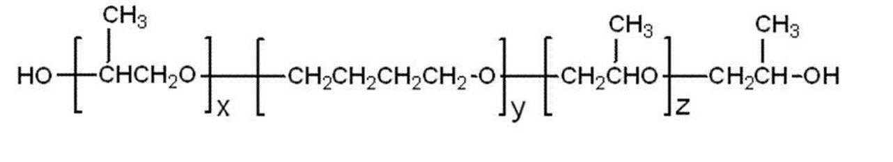
[一般式(3)中、xおよびzは、1~20の整数を表す。yは、4~50の整数を表す。]
前記ポリスチレン系熱可塑性エラストマーは、少なくともポリスチレンがハードセグメントを構成し、他のポリマー(例えば、ポリブタジエン、ポリイソプレン、ポリエチレン、水添ポリブタジエン、水添ポリイソプレン等)が非晶性でガラス転移温度の低いソフトセグメントを構成している材料が挙げられる。前記ハードセグメントを形成するポリスチレンとしては、例えば、公知のラジカル重合法、イオン性重合法で得られるものが好適に使用でき、例えば、アニオンリビング重合を持つポリスチレンが挙げられる。
また、前記ソフトセグメントを構成するポリマーの数平均分子量としては、5000~1000000が好ましく、10000~800000が更に好ましく、30000~500000が特に好ましい。更に、前記ハードセグメント(x)およびソフトセグメント(y)との体積比(x:y)は、成形性の観点から、5:95~80:20が好ましく、10:90~70:30が更に好ましい。
前記ポリスチレン系熱可塑性エラストマーとしては、スチレン-ブタジエン系共重合体[SBS(ポリスチレン-ポリ(ブチレン)ブロック-ポリスチレン)、SEBS(ポリスチレン-ポリ(エチレン/ブチレン)ブロック-ポリスチレン)]、スチレン-イソプレン共重合体[ポリスチレン-ポリイソプレンブロック-ポリスチレン)、スチレン-プロピレン系共重合体[SEP(ポリスチレン-(エチレン/プロピレン)ブロック)、SEPS(ポリスチレン-ポリ(エチレン/プロピレン)ブロック-ポリスチレン)、SEEPS(ポリスチレン-ポリ(エチレン-エチレン/プロピレン)ブロック-ポリスチレン)、SEB(ポリスチレン(エチレン/ブチレン)ブロック)等が挙げられる。
前記ポリウレタン系熱可塑性エラストマーは、少なくともポリウレタンが物理的な凝集によって疑似架橋を形成しているハードセグメントを構成し、他のポリマーが非晶性でガラス転移温度の低いソフトセグメントを構成している材料が挙げられ、例えば、下記式Aで表される単位構造を含むソフトセグメントと、下記式Bで表される単位構造を含むハードセグメントとを含む共重合体として表すことができる。

[前記式中、Pは、長鎖脂肪族ポリエーテルまたは長鎖脂肪族ポリエステルを表す。Rは、脂肪族炭化水素、脂環族炭化水素、芳香族炭化水素を表す。P’は、短鎖脂肪族炭化水素、脂環族炭化水素、または、芳香族炭化水素を表す。]
これらは単独で使用されてもよく、また2種以上が併用されてもよい。
また、前記Rで表される脂環族炭化水素を含むジイソシアネート化合物としては、例えば、1,4-シクロヘキサンジイソシアネートおよび4,4-シクロヘキサンジイソシアネート等が挙げられる。更に、前記Rで表される芳香族炭化水素を含む芳香族ジイソシアネート化合物としては例えば、4,4’-ジフェニルメタンジイソシアネート、トリレンジイソシアネートが挙げられる。
これらは単独で使用されてもよく、また2種以上が併用されてもよい。
また、前記P’で表される脂環族炭化水素を含む脂環族ジオール化合物としては、例えば、シクロペンタン-1,2-ジオール、シクロヘキサン-1,2-ジオール、シクロヘキサン-1,3-ジオール、シクロヘキサン-1,4-ジオール、およびシクロヘキサン-1,4-ジメタノール等が挙げられる。
更に、前記P’で表される芳香族炭化水素を含む芳香族ジオール化合物としては、例えば、ヒドロキノン、レゾルシン、クロロヒドロキノン、ブロモヒドロキノン、メチルヒドロキノン、フェニルヒドロキノン、メトキシヒドロキノン、フェノキシヒドロキノン、4,4’-ジヒドロキシビフェニル、4,4’-ジヒドロキシジフェニルエーテル、4,4’-ジヒドロキシジフェニルサルファイド、4,4’-ジヒドロキシジフェニルスルホン、4,4’-ジヒドロキシベンゾフェノン、4,4’-ジヒドロキシジフェニルメタン、ビスフェノールA、1,1-ジ(4-ヒドロキシフェニル)シクロヘキサン、1,2-ビス(4-ヒドロキシフェノキシ)エタン、1,4-ジヒドロキシナフタリン、および2,6-ジヒドロキシナフタリン等が挙げられる。
これらは単独で使用されてもよく、また2種以上が併用されてもよい。
前記ポリウレタン系熱可塑性エラストマーは、前記ハードセグメントを形成するポリマー及びソフトセグメントを形成するポリマーを公知の方法によって共重合することで合成することができる。前記ポリウレタン系熱可塑性エラストマーとしては、例えば、特開平5-331256に記載の熱可塑性ポリウレタンを用いることができる。
前記ポリウレタン系熱可塑性エラストマーとして、具体的には、芳香族ジオールと芳香族ジイソシアネートとからなるハードセグメントと、ポリ炭酸エステルからなるソフトセグメントの組合せが好ましく、トリレンジイソシアネート(TDI)/ポリエステル系ポリオール共重合体、TDI/ポリエーテル系ポリオール共重合体、TDI/カプロラクトン系ポリオール共重合体、TDI/ポリカーボネート系ポリオール共重合体、4,4’-ジフェニルメタンジイソシアネート(MDI)/ポリエステル系ポリオール共重合体、MDI/ポリエーテル系ポリオール共重合体、MDI/カプロラクトン系ポリオール共重合体、MDI/ポリカーボネート系ポリオール共重合体、MDI+ヒドロキノン/ポリヘキサメチレンカーボネート共重合体が好ましく、TDI/ポリエステル系ポリオール共重合体、TDI/ポリエーテル系ポリオール共重合体、MDI/ポリエステルポリオール共重合体、MDI/ポリエーテル系ポリオール共重合体、MDI+ヒドロキノン/ポリヘキサメチレンカーボネート共重合体が更に好ましい。
前記ポリオレフィン系熱可塑性エラストマーは、少なくともポリオレフィンが結晶性で融点の高いハードセグメントを構成し、他のポリマー(例えば、前記ポリオレフィン、他のポリオレフィン、ポリビニル化合物)が非晶性でガラス転移温度の低いソフトセグメントを構成している材料が挙げられる。前記ハードセグメントを形成するポリオレフィンとしては、例えば、ポリエチレン、ポリプロピレン、アイソタクチックポリプロピレン、ポリブテン等が挙げられる。
前記ポリオレフィン系熱可塑性エラストマーとしては、オレフィン-α-オレフィンランダム共重合体、オレフィンブロック共重合体等が挙げられ、例えば、プロピレンブロック共重合体、エチレン-プロピレン共重合体、プロピレン-1-ヘキセン共重合体、プロピレン-4-メチル-1ペンテン共重合体、プロピレン-1-ブテン共重合体、エチレン-1-ヘキセン共重合体、エチレン-4-メチル-ペンテン共重合体、エチレン-1-ブテン共重合体、1-ブテン-1-ヘキセン共重合体、1-ブテン-4-メチル-ペンテン、エチレン-メタクリル酸共重合体、エチレン-メタクリル酸メチル共重合体、エチレン-メタクリル酸エチル共重合体、エチレン-メタクリル酸ブチル共重合体、エチレン-メチルアクリレート共重合体、エチレン-エチルアクリレート共重合体、エチレン-ブチルアクリレート共重合体、プロピレン-メタクリル酸共重合体、プロピレン-メタクリル酸メチル共重合体、プロピレン-メタクリル酸エチル共重合体、プロピレン-メタクリル酸ブチル共重合体、プロピレン-メチルアクリレート共重合体、プロピレン-エチルアクリレート共重合体、プロピレン-ブチルアクリレート共重合体、エチレン-酢酸ビニル共重合体、プロピレン-酢酸ビニル共重合体等が挙げられる。
また、エチレンとプロピレンといったように2種以上のポリオレフィン樹脂を組み合わせて使用してもよい。また、前記ポリオレフィン系熱可塑性エラストマー中のポリオレフィン含率は、50質量%以上100質量%以下が好ましい。
更に、前記ポリオレフィン系熱可塑性エラストマーとしては、例えば、市販品のプライムポリマー製の「プライムTPO」シリーズ(例えば、E-2900H、F-3900H、E-2900、F-3900、J-5900、E-2910、F-3910、J-5910、E-2710、F-3710、J-5910、E-2740、F-3740、R110MP、R110E、T310E、M142E等)等も用いることができる。
前記ポリエステル系熱可塑性エラストマーは、少なくともポリエステルが結晶性で融点の高いハードセグメントを構成し、他のポリマー(例えば、ポリエステルまたはポリエーテル等)が非晶性でガラス転移温度の低いソフトセグメントを構成している材料が挙げられる。
前記ハードセグメントを形成するポリエステルとしては、例えば、ポリエチレンテレフタレート、プリブチレンテレフタレート、ポリメチレンテレフタレート、ポリエチレンナフタレート、ポリブチレンナフタレート等が挙げられ、ポリブチレンテレフタレートが好ましい。
前記脂肪族ポリエーテルとしては、ポリ(エチレンオキシド)グリコール、ポリ(プロピレンオキシド)グリコール、ポリ(テトラメチレンオキシド)グリコール、ポリ(ヘキサメチレンオキシド)グリコール、エチレンオキシドとプロピレンオキシドの共重合体、ポリ(プロピレンオキシド)グリコールのエチレンオキシド付加重合体、エチレンオキシドとテトラヒドロフランの共重合体等が挙げられる。
前記脂肪族ポリエステルとしては、ポリ(ε-カプロラクトン)、ポリエナントラクトン、ポリカプリロラクトン、ポリブチレンアジペート、ポリエチレンアジペートなどが挙げられる。
これらの脂肪族ポリエーテルおよび脂肪族ポリエステルのなかでも、得られるポリエステルブロック共重合体の弾性特性の観点から、ポリ(テトラメチレンオキシド)グリコール、ポリ(プロピレンオキシド)グリコールのエチレンオキシド付加物、ポリ(ε-カプロラクトン)、ポリブチレンアジペート、ポリエチレンアジペートなどが好ましい。
前記「熱可塑性エラストマーを酸変性してなるもの」とは、熱可塑性エラストマーに、カルボン酸基、硫酸基、燐酸基等の酸性基を有する不飽和化合物を結合させることをいう。例えば、酸性基を有する不飽和化合物として、不飽和カルボン酸(一般的には、無水マレイン酸)を用いるとき、オレフィン系熱可塑性エラストマーに、不飽和カルボン酸の不飽和結合部位を結合(例えば、グラフト重合)させることが挙げられる。
また、タイヤの耐久性や生産性を向上させることができる。前記樹脂材料には、所望に応じて、ゴム、エラストマー、熱可塑性樹脂、各種充填剤(例えば、シリカ、炭酸カルシウム、クレイ)、老化防止剤、オイル、可塑剤、発色剤、耐候剤等の各種添加剤を含有(ブレンド)させてもよい。
本発明の第1の実施形態のタイヤは、少なくとも樹脂材料で形成され且つ積層構造を有する環状のタイヤ骨格体を有し、前記タイヤ骨格体は、80℃におけるガス透過係数が2.0×10⁻¹⁵cm3・cm/(cm2・s・Pa)以下のガス保持層を少なくとも一層含む。
本発明の第1の実施形態のタイヤは、樹脂材料で形成された環状のタイヤ骨格体を有する。本発明の第1の実施形態のタイヤは、タイヤ骨格体が樹脂材料で形成されているため、従来のゴム製タイヤで必須工程であった加硫工程を必須とせず、例えば、射出成形等でタイヤ骨格体を成形することができる。このため、製造工程の簡素化、時間短縮及びコストダウンなどを図ることができる。また、樹脂材料を用いて形成されたタイヤ骨格体は、一般に従来のゴム製のタイヤに比して構造が簡易であるため重量が軽いという利点がある。このため、タイヤの耐摩耗性や転がり抵抗を向上させることができる。
前記ガス保持層の4%引張り伸張時の応力は、50MPa以下が好ましく、40MPa以下が更に好ましい。
以下に、図面に従って本発明の第1の実施形態について、第1-1の実施形態に係るタイヤを例に説明する。
本実施形態のタイヤ10について説明する。本実施形態においては、タイヤケース10の径方向最内側にポリアミド系熱可塑性樹脂(ポリアミド6)によって構成されたガス保持層が設けられている。図1Aは、本発明の一実施形態に係るタイヤの一部の断面を示す斜視図である。図1Bは、リムに装着したビード部の断面図である。図1Aに示すように、本実施形態のタイヤ10は、従来一般のゴム製の空気入りタイヤと略同様の断面形状を呈している。
また、本実施形態では、タイヤケース半体17Aは左右対称形状、即ち、一方のタイヤケース半体17Aと他方のタイヤケース半体17Aとが同一形状とされているので、タイヤケース半体17Aを成形する金型が1種類で済むメリットもある。
まず、薄い金属の支持リングに支持されたタイヤケース半体同士を互いに向かい合わせる。次いで、タイヤケース半体の突き当て部分の外周面と接するように図を省略する接合金型を設置する。ここで、前記接合金型はタイヤケース半体17Aの接合部(突き当て部分)周辺を所定の圧力で押圧するように構成されている。次いで、タイヤケース半体の接合部周辺を、タイヤケースを構成する熱可塑性樹脂材料の融点以上で押圧する。タイヤケース半体の接合部が接合金型によって加熱・加圧されると、前記接合部が溶融しタイヤケース半体同士が融着しこれら部材が一体となってタイヤケース17が形成される。尚、本実施形態においては接合金型を用いてタイヤケース半体の接合部を加熱したが、本発明はこれに限定されず、例えば、別に設けた高周波加熱機等によって前記接合部を加熱したり、予め熱風、赤外線の照射等によって軟化または溶融させ、接合金型によって加圧してタイヤケース半体を接合させてもよい。
次に、補強コード巻回工程について図4を用いて説明する。図4は、コード加熱装置、およびローラ類を用いてタイヤケースのクラウン部に補強コードを埋設する動作を説明するための説明図である。図4において、コード供給装置56は、補強コード26を巻き付けたリール58と、リール58のコード搬送方向下流側に配置されたコード加熱装置59と、補強コード26の搬送方向下流側に配置された第1のローラ60と、第1のローラ60をタイヤ外周面に対して接離する方向に移動する第1のシリンダ装置62と、第1のローラ60の補強コード26の搬送方向下流側に配置される第2のローラ64と、および第2のローラ64をタイヤ外周面に対して接離する方向に移動する第2のシリンダ装置66と、を備えている。第2のローラ64は、金属製の冷却用ローラとして利用することができる。また、本実施形態において、第1のローラ60または第2のローラ64の表面は、溶融または軟化したポリアミド系熱可塑性エラストマーの付着を抑制するためにフッ素樹脂(本実施形態では、テフロン(登録商標))でコーティングされている。なお、本実施形態では、コード供給装置56は、第1のローラ60または第2のローラ64の2つのローラを有する構成としているが、本発明はこの構成に限定されず、何れか一方のローラのみ(即ち、ローラ1個)を有している構成でもよい。
次に、タイヤケース17を、図示を省略するブロー成型装置に設置する。次いで、溶融したポリアミド6をダイスから押出し、タイヤケース17の径方向内側の全面にポリアミド6の層が形成されるようにブロー成形を行う。この際、溶融したポリアミド6の押出量は、上述のガス保持層2Aの膜厚100μmとなるように決定される。これによってタイヤケース17の径方向内側にガス保持層2Aが形成される。尚、前記ブロー成形は公知の方法に準じて行うことができる。
本実施形態のタイヤ10は、タイヤケース17Aの径方向内側にガス透過係数は2.0×10⁻¹⁵cm3・cm/(cm2・s・Pa)のガス保持層2Aが形成されているため、タイヤ10のガス保持特性を向上させることができる。このため、本実施形態のタイヤ10はリム20に組み込んだ際、タイヤ10内部に充填されるガスの保持特性が高い。
このように補強コード層28が、ポリアミド系熱可塑性エラストマーを含んで構成されていると、補強コード26をクッションゴムで固定する場合と比してタイヤケース17と補強コード層28との硬さの差を小さくできるため、更に補強コード26をタイヤケース17に密着・固定することができる。これにより、上述のエア入りを効果的に防止することができ、走行時に補強コード部材が動くのを効果的に抑制することができる。
更に、補強コード26がスチールコードの場合に、タイヤ処分時に補強コード26を加熱によってポリアミド系熱可塑性エラストマーから容易に分離・回収が可能であるため、タイヤ10のリサイクル性の点で有利である。また、ポリアミド系熱可塑性エラストマーは加硫ゴムに比して損失係数(Tanδ)が低いため、補強コード層28がポリアミド系熱可塑性エラストマーを多く含んでいると、タイヤの転がり性を向上させることができる。更には、ポリアミド系熱可塑性エラストマーは加硫ゴムに比して、面内せん断剛性が大きく、タイヤ走行時の操安性や耐摩耗性にも優れるといった利点がある。
さらに、ビード部12には、金属材料からなる環状のビードコア18が埋設されていることから、従来のゴム製の空気入りタイヤと同様に、リム20に対してタイヤケース17、すなわちタイヤ10が強固に保持される。
以上、実施形態を挙げて本発明の実施の形態を説明したが、これらの実施形態は一例であり、要旨を逸脱しない範囲内で種々変更して実施できる。また、本発明の権利範囲がこれらの実施形態に限定されないことは言うまでもない。
次に、図面に従って本発明の第1-2実施形態について説明する。本実施形態においては、タイヤケース200の径方向最内側から2番目の層に、エチレン-ビニルアルコール共重合体(EVOH)によって構成されたガス保持層が設けられている。本実施形態のタイヤは、上述の第1-1実施形態と同様に、従来一般のゴム製の空気入りタイヤと略同様の断面形状を呈している。このため、以下の図において、前記第1-1実施形態と同様の構成については同様の番号が付される。また、図5AにおけるM領域の拡大図(図6)に示されるように、ガス保持層2Bが設けられている。図6は、本実施形態のガス保持層を説明するための拡大図である。
(骨格形成工程)
まず、上述の第1-1実施形態と同様にして、タイヤケース半体17Aを形成し、これを接合金型によって加熱・押圧し、タイヤケース17を形成する。
本実施形態におけるタイヤの製造装置は、上述の第1-1実施形態と同様であり、上述の第1-1実施形態の図4に示すコード供給装置56において、リール58にコード部材26Aを被覆用樹脂材料27(本実施形態では熱可塑性材料)で被覆した断面形状が略台形状の被覆コード部材26Bを巻き付けたものが用いられる。
次に、図示を省略するブラスト装置にて、タイヤケース17の外周面17Sに向け、タイヤケース17側を回転させながら、外周面17Sへ投射材を高速度で射出する。射出された投射材は、外周面17Sに衝突し、この外周面17Sに算術平均粗さRaが0.05mm以上となる微細な粗化凹凸96を形成する。
このようにして、タイヤケース17の外周面17Sに微細な粗化凹凸96が形成されることで、外周面17Sが親水性となり、後述する接合剤の濡れ性が向上する。
次に、粗化処理を行なったタイヤケース17の外周面17Sに接合剤を塗布する。
なお、接合剤としては、トリアジンチオール系接着剤、塩化ゴム系接着剤、フェノール系樹脂接着剤、イソシアネート系接着剤、ハロゲン化ゴム系接着剤、ゴム系接着剤など、特に制限はないが、クッションゴム29が加硫できる温度(90℃~140℃)で反応することが好ましい。
次に生タイヤケースを加硫缶やモールドに収容して加硫する。このとき、粗化処理によってタイヤケース17の外周面17Sに形成された粗化凹凸96に未加硫のクッションゴム29が流れ込む。そして、加硫が完了すると、粗化凹凸96に流れ込んだクッションゴム29により、アンカー効果が発揮されて、タイヤケース17とクッションゴム29との接合強度が向上する。すなわち、クッションゴム29を介してタイヤケース17とトレッド30との接合強度が向上する。
次に、タイヤケース17を、図示を省略するブロー成型装置に設置する。次いで、溶融したEVOHをダイスから押出し、タイヤケース17の径方向内側の全面にEVOHの層が形成されるようにブロー成形を行う。この際、溶融したEVOHの押出量は、上述のガス保持層2Bの膜厚100μmとなるように決定される。ガス保持層2Bを形成した後、更に、溶融したポリアミド系熱可塑性エラストマー(上述の宇部興産(株)製「UBESTA XPA9055X1」)を押出し、ブロー成型によってEVOH層表面にポリアミド系熱可塑性エラストマーからなる層を形成する。これによってタイヤケース17の径方向内側から2層目にEVOHからなるガス保持層2Bが形成されたタイヤケース17が形成される。尚、前記ブロー成形は公知の方法に準じて行うことができる。
本実施形態のタイヤ200は、タイヤケース17Aの径方向内側から2層目にガス透過係数は1.00×10⁻¹⁷cm3・cm/(cm2・s・Pa)のガス保持層2Bが形成されているため、タイヤ10のガス保持特性を向上させることができる。このため、本実施形態のタイヤ200はリム20に組み込んだ際、タイヤ200内部に充填されるガスの保持特性が高い。
また、本実施形態では、ガス保持層2BがEVOHで形成されているため、ガス保持層2Bの形成によってもタイヤ200の重量の増加が抑制されており、ポリアミド系熱可塑性エラストマーで形成されているタイヤケース17との接着性(熱融着性)も高い。また、ガス保持層2Bの4%引張り伸張時の応力が52MPaであるため、タイヤ200への衝撃等に対するガス保持層2Bの耐久性が高い。
更に、本実施形態のタイヤ200では、タイヤケース17がポリアミド系熱可塑性エラストマーによって形成されているため、耐熱性、引張弾性率、引張強度及び破断ひずみに優れ、さらに従来のゴム製のタイヤに比して構造が簡易であるため重量が軽い。このため、本実施形態のタイヤ200は、耐摩擦性および耐久性が高い。さらに、タイヤケース17を構成するポリアミド系熱可塑性エラストマーは、融点が154℃であるためタイヤケース片17Aの接合を例えば、210℃程度で十分に行うことができるため、エネルギー消費を抑制でき加熱にかかるコストを抑制することができる。また、ポリアミドラストマーは被覆コード部材26Bに対する接着性が高い。
更に、補強コード26Aがスチールコードの場合に、タイヤ処分時に被覆コード部材26Bからコード部材26Aを加熱によって容易に分離・回収が可能であるため、タイヤ200のリサイクル性の点で有利である。また、ポリアミド系熱可塑性エラストマーは加硫ゴムに比して損失係数(Tanδ)が低いため、補強コード層28がポリアミド系熱可塑性エラストマーを多く含んでいると、タイヤの転がり性を向上させることができる。更には、ポリアミド系熱可塑性エラストマーは加硫ゴムに比して、面内せん断剛性が大きく、タイヤ走行時の操安性や耐摩耗性にも優れるといった利点がある。
また、タイヤケース17は、タイヤケースのクラウン部に巻回され且つ接合された被覆コード部材を被覆用熱可塑性材料で覆うようにして補強コード層を形成してもよい。この場合、溶融または軟化状態の被覆用熱可塑性材料を補強コード層28の上に吐出して被覆層を形成することができる。また、押出機を用いずに、溶着シートを加熱し溶融または軟化状態にして、補強コード層28の表面(外周面)に貼り付けて被覆層を形成してもよい。
また、被覆コード部材26Bを形成する被覆用樹脂材料27を熱硬化性樹脂とし、被覆コード部材26Bを加熱せずに接着剤などを用いてクラウン部16の外周面に接着する構成としてもよい。
さらに、被覆コード部材26Bを形成する被覆用樹脂材料27を熱硬化性樹脂とし、タイヤケース17を熱可塑性材料で形成する構成としてもよい。この場合には、被覆コード部材26Bをクラウン部16の外周面に接着剤などを用いて接着してもよく、タイヤケース17の被覆コード部材26Bが配設される部位を加熱して溶融又は軟化状態にして被覆コード部材26Bをクラウン部16の外周面に溶着してもよい。
またさらに、被覆コード部材26Bを形成する被覆用樹脂材料27を熱可塑性材料とし、タイヤケース17を熱可塑性材料で形成する構成としてもよい。この場合には、被覆コード部材26Bをクラウン部16の外周面に接着剤などを用いて接着してもよく、タイヤケース17の被覆コード部材26Bが配設される部位を加熱して溶融又は軟化状態としつつ、被覆用樹脂材料27を加熱し溶融又は軟化状態にして被覆コード部材26Bをクラウン部16の外周面に溶着してもよい。なお、タイヤケース17及び被覆コード部材26Bの両者を加熱して溶融又は軟化状態にした場合、両者が良く混ざり合うため接合強度が向上する。また、タイヤケース17を形成する樹脂材料、及び被覆コード部材26Bを形成する被覆用樹脂材料27をともに熱可塑性材料とする場合には、同種の熱可塑性材料、特に同一の熱可塑性材料とすることが好ましい。
また、さらに粗化処理を行ったタイヤケース17の外周面17Sにコロナ処理やプラズマ処理等を用い、外周面17Sの表面を活性化し、親水性を高めた後に接着剤を塗布してもよい。
以上、実施形態を挙げて本発明の実施の形態を説明したが、これらの実施形態は一例であり、要旨を逸脱しない範囲内で種々変更して実施できる。また、本発明の権利範囲がこれらの実施形態に限定されないことは言うまでもない。
本発明の第2の実施形態のタイヤは、少なくとも樹脂材料で形成され且つ積層構造を有する環状のタイヤ骨格体を有し、前記タイヤ骨格体は、ポリアミド系熱可塑性樹脂とエラストマーとからなる樹脂組成物を含む80℃におけるガス透過係数が2.0×10⁻¹⁴cm3・cm/(cm2・s・Pa)以下のガス保持層を少なくとも一層含むように構成される。
本発明の第2の実施形態のタイヤは、タイヤ骨格体が積層構造を有し、少なくとも一層の80℃におけるガス透過係数が2.0×10⁻¹⁴cm3・cm/(cm2・s・Pa)以下のガス保持層を有する。当該ガス保持層は、ポリアミド系熱可塑性樹脂とエラストマーとからなる樹脂組成物を有している。本発明の第2の実施形態のタイヤは、前記タイヤ骨格体に前記ガス保持層を備えるため、タイヤ骨格体の空気や窒素ガス等のガスに対するガス保持特性を向上させることができる。このため、本発明のタイヤは、前記タイヤ骨格体がリムに取り付けられタイヤ骨格体とリムとに囲まれた空洞内にガスが充填される所謂空気入りタイヤとして有効に用いることができる。また、タイヤのガス保持特性が向上すると、タイヤの内圧保持特性も同時に向上する。
前記ポリアミド系熱可塑性樹脂に対する前記エラストマーの含有率は、20~45体積%であることが更に好ましい。
前記ガス保持層の引張弾性率は、40MPa以下が好ましく、30MPa以下が更に好ましい。
以下に、図面に従って本発明の第2の実施形態について、第2-1の実施形態に係るタイヤを例に説明する。本発明の第2-1の実施形態に係るタイヤは、第1-1の実施形態のタイヤにおいて、図1~4にて説明されているタイヤ10のガス保持層2Aが、ポリアミド系熱可塑性樹脂(ポリアミド6)及び2種のポリオレフィン系エラストマー(エチレン・ブテン共重合体)からなる樹脂組成物によって構成されたガス保持層(2.0×10⁻¹⁴cm3・cm/(cm2・s・Pa))である点以外は同様の構成を有している。このため、以下、図1~4を援用して、本実施形態について説明し、同様の部材については説明を省略する。
本実施形態のタイヤ10について説明する。本実施形態においては、タイヤケース10の径方向最内側にポリアミド系熱可塑性樹脂(ポリアミド6)及び2種のポリオレフィン系エラストマー(エチレン・ブテン共重合体)からなる樹脂組成物によって構成されたガス保持層(2.0×10⁻¹⁴cm3・cm/(cm2・s・Pa))が設けられている。
本実施形態のタイヤ10は、タイヤケース17Aの径方向内側にガス透過係数ポリアミド系熱可塑性樹脂(ポリアミド6)とポリオレフィン系エラストマー(エチレン・ブテン共重合体(2種))との樹脂組成物を有する2.0×10⁻¹⁴cm3・cm/(cm2・s・Pa)のガス保持層2Aが形成されているため、ガス保持層2Aの柔軟性を高めつつタイヤ10のガス保持特性を向上させることができる。このため、本実施形態のタイヤ10はリム20に組み込んだ際にタイヤ10内部に充填されるガスの保持特性が高い。
このように補強コード層28が、ポリアミド系熱可塑性エラストマーを含んで構成されていると、補強コード26をクッションゴムで固定する場合と比してタイヤケース17と補強コード層28との硬さの差を小さくできるため、更に補強コード26をタイヤケース17に密着・固定することができる。これにより、上述のエア入りを効果的に防止することができ、走行時に補強コード部材が動くのを効果的に抑制することができる。
更に、補強コード26がスチールコードの場合に、タイヤ処分時に補強コード26を加熱によってポリアミド系熱可塑性エラストマーから容易に分離・回収が可能であるため、タイヤ10のリサイクル性の点で有利である。また、ポリアミド系熱可塑性エラストマーは加硫ゴムに比して損失係数(Tanδ)が低いため、補強コード層28がポリアミド系熱可塑性エラストマーを多く含んでいると、タイヤの転がり性を向上させることができる。更には、ポリアミド系熱可塑性エラストマーは加硫ゴムに比して、面内せん断剛性が大きく、タイヤ走行時の操安性や耐摩耗性にも優れるといった利点がある。
さらに、ビード部12には、金属材料からなる環状のビードコア18が埋設されていることから、従来のゴム製の空気入りタイヤと同様に、リム20に対してタイヤケース17、すなわちタイヤ10が強固に保持される。
以上、実施形態を挙げて本発明の実施の形態を説明したが、これらの実施形態は一例であり、要旨を逸脱しない範囲内で種々変更して実施できる。また、本発明の権利範囲がこれらの実施形態に限定されないことは言うまでもない。
次に、図面に従って本発明の第2-2実施形態について説明する。本発明の第2-2の実施形態に係るタイヤは、第1-2の実施形態のタイヤにおいて、図5~7にて説明されているタイヤ200のガス保持層2Bが、ポリアミド系熱可塑性樹脂(ポリアミドMX)及びポリオレフィン系エラストマー(エチレン・ブテン共重合体)からなる樹脂組成物によって構成されたガス保持層(ガス透過率1.0×10⁻¹⁴cm3・cm/(cm2・s・Pa)である点以外は同様の構成を有している。このため、以下、図5~7を援用して、本実施形態について説明し、同様の部材の説明については説明を省略する。
本実施形態のタイヤ200は、タイヤケース17Aの径方向内側から2層目にポリアミド系熱可塑性樹脂(ポリアミドMX)とポリオレフィン系エラストマー(エチレン・ブテン共重合体)との樹脂組成物によって形成されたガス透過係数は1.0×10⁻¹⁴cm3・cm/(cm2・s・Pa))のガス保持層2Bを有するため、ガス保持層2Bの柔軟性を高めつつタイヤ200のガス保持特性を向上させることができる。このため、本実施形態のタイヤ200はリム20に組み込んだ際、タイヤ200内部に充填されるガスの保持特性が高い。
また、本実施形態では、ガス保持層2Bがポリアミド系熱可塑性樹脂であるポリアミド系熱可塑性樹脂とポリオレフィン系エラストマーとで形成されているため、ガス保持層2Bの形成によってもタイヤ200の重量の増加が抑制されており、ポリアミド系熱可塑性エラストマーで形成されているタイヤケース17との接着性(熱融着性)も高い。また、ガス保持層2Bの4%引張伸張時における応力が、38MPaであるため、タイヤ200への衝撃等に対するガス保持層2Bの耐久性が高い。
更に、本実施形態のタイヤ200では、タイヤケース17がポリアミド系熱可塑性エラストマーによって形成されているため、耐熱性、引張弾性率、引張強度及び破断ひずみに優れ、さらに従来のゴムに比して構造が簡易であるため重量が軽い。このため、本実施形態のタイヤ200は、耐摩擦性および耐久性が高い。さらに、タイヤケース17を構成するポリアミド系熱可塑性エラストマーは、融点が162℃であるためタイヤケース片17Aの接合を例えば、210℃程度で十分に行うことができるため、エネルギー消費を抑制でき加熱にかかるコストを抑制することができる。また、ポリアミドラストマーは被覆コード部材26Bに対する接着性が高い。
更に、補強コード26Aがスチールコードの場合に、タイヤ処分時に被覆コード部材26Bからコード部材26Aを加熱によって容易に分離・回収が可能であるため、タイヤ200のリサイクル性の点で有利である。また、ポリアミド系熱可塑性エラストマーは加硫ゴムに比して損失係数(Tanδ)が低いため、補強コード層28がポリアミド系熱可塑性エラストマーを多く含んでいると、タイヤの転がり性を向上させることができる。更には、ポリアミド系熱可塑性エラストマーは加硫ゴムに比して、面内せん断剛性が大きく、タイヤ走行時の操安性や耐摩耗性にも優れるといった利点がある。
また、タイヤケース17は、タイヤケースのクラウン部に巻回され且つ接合された被覆コード部材を被覆用熱可塑性材料で覆うようにして補強コード層を形成してもよい。この場合、溶融または軟化状態の被覆用熱可塑性材料を補強コード層28の上に吐出して被覆層を形成することができる。また、押出機を用いずに、溶着シートを加熱し溶融または軟化状態にして、補強コード層28の表面(外周面)に貼り付けて被覆層を形成してもよい。
また、被覆コード部材26Bを形成する被覆用樹脂材料27を熱硬化性樹脂とし、被覆コード部材26Bを加熱せずに接着剤などを用いてクラウン部16の外周面に接着する構成としてもよい。
さらに、被覆コード部材26Bを形成する被覆用樹脂材料27を熱硬化性樹脂とし、タイヤケース17を熱可塑性材料で形成する構成としてもよい。この場合には、被覆コード部材26Bをクラウン部16の外周面に接着剤などを用いて接着してもよく、タイヤケース17の被覆コード部材26Bが配設される部位を加熱して溶融又は軟化状態にして被覆コード部材26Bをクラウン部16の外周面に溶着してもよい。
またさらに、被覆コード部材26Bを形成する被覆用樹脂材料27を熱可塑性材料とし、タイヤケース17を熱可塑性材料で形成する構成としてもよい。この場合には、被覆コード部材26Bをクラウン部16の外周面に接着剤などを用いて接着してもよく、タイヤケース17の被覆コード部材26Bが配設される部位を加熱して溶融又は軟化状態としつつ、被覆用樹脂材料27を加熱し溶融又は軟化状態にして被覆コード部材26Bをクラウン部16の外周面に溶着してもよい。なお、タイヤケース17及び被覆コード部材26Bの両者を加熱して溶融又は軟化状態にした場合、両者が良く混ざり合うため接合強度が向上する。また、タイヤケース17を形成する樹脂材料、及び被覆コード部材26Bを形成する被覆用樹脂材料27をともに熱可塑性材料とする場合には、同種の熱可塑性材料、特に同一の熱可塑性材料とすることが好ましい。
また、さらに粗化処理を行ったタイヤケース17の外周面17Sにコロナ処理やプラズマ処理等を用い、外周面17Sの表面を活性化し、親水性を高めた後に接着剤を塗布してもよい。
以上、実施形態を挙げて本発明の実施の形態を説明したが、これらの実施形態は一例であり、要旨を逸脱しない範囲内で種々変更して実施できる。また、本発明の権利範囲がこれらの実施形態に限定されないことは言うまでもない。
本発明の第3の実施形態のタイヤは、タイヤ骨格体が積層構造を有し、少なくとも一層のガス保持層を有する。当該ガス保持層は、エチレン-ビニルアルコール共重合体と、エラストマーと、を有している。エチレン-ビニルアルコール共重合体は、ガスバリア性に優れる材料であるため、本発明のタイヤは前記タイヤ骨格体に前記ガス保持層を備えることで、タイヤ骨格体の空気や窒素ガス等のガスに対するガス保持特性を向上させることができる。このため、本発明のタイヤは、前記タイヤ骨格体がリムに取り付けられタイヤ骨格体とリムとに囲まれた空洞内にガスが充填される所謂空気入りタイヤとして有効に用いることができる。また、タイヤのガス保持特性が向上すると、タイヤの内圧保持特性も同時に向上する。
また、エチレン-ビニルアルコール共重合体とエラストマーとを有するガス保持層は強度および接着性が十分であるため、ガス保持層を薄くできるという利点がある。
前記エチレン-ビニルアルコール共重合体に対する前記エラストマーの含有率は、25~45体積%であることが更に好ましい。
前記ガス保持層の引張弾性率は、30MPa以下が更に好ましい。
以下に、図面に従って本発明の第3の実施形態について、第3-1の実施形態に係るタイヤを例に説明する。本実施形態のタイヤ10について説明する。本発明の第3-1の実施形態に係るタイヤは、第1-1の実施形態のタイヤにおいて、図1~4にて説明されているタイヤ10のガス保持層2Aが、エチレン-ビニルアルコール共重合体(エチレン含有率:27モル%)及び2種のポリオレフィン系エラストマー(エチレン・ブテン共重合体)によって構成されたガス保持層である点以外は同様の構成を有している。このため、以下、図1~4を援用して、本実施形態について説明し、同様の部材については説明を省略する。
本実施形態のタイヤ10について説明する。本実施形態においては、タイヤケース10の径方向最内側にエチレン-ビニルアルコール共重合体(エチレン含有率:27モル%)及び2種のポリオレフィン系エラストマー(エチレン・ブテン共重合体)によって構成されたガス保持層が設けられている。
本実施形態のタイヤ10は、タイヤケース17Aの径方向内側にエチレン-ビニルアルコール共重合体(EVOH)とポリオレフィン系エラストマー(エチレン・ブテン共重合体(2種))との混合物によってガス保持層2Aが形成されているため、ガス保持層2Aの柔軟性を高めつつタイヤ10のガス保持特性を向上させることができる。このため、本実施形態のタイヤ10はリム20に組み込んだ際にタイヤ10内部に充填されるガスの保持特性が高い。
このように補強コード層28が、ポリアミド系熱可塑性エラストマーを含んで構成されていると、補強コード26をクッションゴムで固定する場合と比してタイヤケース17と補強コード層28との硬さの差を小さくできるため、更に補強コード26をタイヤケース17に密着・固定することができる。これにより、上述のエア入りを効果的に防止することができ、走行時に補強コード部材が動くのを効果的に抑制することができる。
更に、補強コード26がスチールコードの場合に、タイヤ処分時に補強コード26を加熱によってポリアミド系熱可塑性エラストマーから容易に分離・回収が可能であるため、タイヤ10のリサイクル性の点で有利である。また、ポリアミド系熱可塑性エラストマーは加硫ゴムに比して損失係数(Tanδ)が低いため、補強コード層28がポリアミド系熱可塑性エラストマーを多く含んでいると、タイヤの転がり性を向上させることができる。更には、ポリアミド系熱可塑性エラストマーは加硫ゴムに比して、面内せん断剛性が大きく、タイヤ走行時の操安性や耐摩耗性にも優れるといった利点がある。
さらに、ビード部12には、金属材料からなる環状のビードコア18が埋設されていることから、従来のゴム製の空気入りタイヤと同様に、リム20に対してタイヤケース17、すなわちタイヤ10が強固に保持される。
以上、実施形態を挙げて本発明の実施の形態を説明したが、これらの実施形態は一例であり、要旨を逸脱しない範囲内で種々変更して実施できる。また、本発明の権利範囲がこれらの実施形態に限定されないことは言うまでもない。
次に、図面に従って本発明の第3-2実施形態について説明する。本発明の第3-2の実施形態に係るタイヤは、第1-2の実施形態のタイヤにおいて、図5~7にて説明されているタイヤ200のガス保持層2Bが、エチレン-ビニルアルコール共重合体(エチレン含有率:27モル%)及びポリオレフィン系エラストマー(エチレン・ブテン共重合体)によって構成されたガス保持層である点以外は同様の構成を有している。このため、以下、図5~7を援用して、本実施形態について説明し、同様の部材については説明を省略する。
本実施形態のタイヤ200は、タイヤケース17Aの径方向内側から2層目にエチレン-ビニルアルコール共重合体(EVOH)とポリオレフィン系エラストマー(エチレン・ブテン共重合体)との混合物によってガス保持層2Bが形成されているため、ガス保持層2Bの柔軟性を高めつつタイヤ200のガス保持特性を向上させることができる。このため、本実施形態のタイヤ200はリム20に組み込んだ際、タイヤ200内部に充填されるガスの保持特性が高い。
また、本実施形態では、ガス保持層2Bがエチレン-ビニルアルコール共重合体であるエチレン-ビニルアルコール共重合体とポリオレフィン系エラストマーとで形成されているため、ガス保持層2Bの形成によってもタイヤ200の重量の増加が抑制されており、ポリアミド系熱可塑性エラストマーで形成されているタイヤケース17との接着性(熱融着性)も高い。また、ガス保持層2Bの弾性率が4%引張り伸張時における応力が28MPaであるため、タイヤ200への衝撃等に対するガス保持層2Bの耐久性が高い。
更に、本実施形態のタイヤ200では、タイヤケース17がポリアミド系熱可塑性エラストマーによって形成されているため、耐熱性、引張弾性率、引張強度及び破断ひずみに優れ、さらに従来のゴムに比して構造が簡易であるため重量が軽い。このため、本実施形態のタイヤ200は、耐摩擦性および耐久性が高い。さらに、タイヤケース17を構成するポリアミド系熱可塑性エラストマーは、融点が162℃であるためタイヤケース片17Aの接合を例えば、210℃程度で十分に行うことができるため、エネルギー消費を抑制でき加熱にかかるコストを抑制することができる。また、ポリアミドラストマーは被覆コード部材26Bに対する接着性が高い。
更に、補強コード26Aがスチールコードの場合に、タイヤ処分時に被覆コード部材26Bからコード部材26Aを加熱によって容易に分離・回収が可能であるため、タイヤ200のリサイクル性の点で有利である。また、ポリアミド系熱可塑性エラストマーは加硫ゴムに比して損失係数(Tanδ)が低いため、補強コード層28がポリアミド系熱可塑性エラストマーを多く含んでいると、タイヤの転がり性を向上させることができる。更には、ポリアミド系熱可塑性エラストマーは加硫ゴムに比して、面内せん断剛性が大きく、タイヤ走行時の操安性や耐摩耗性にも優れるといった利点がある。
本実施形態では、タイヤケース17の外周面17Sに凹凸を構成したが、本発明はこれに限らず、外周面17Sを平らに形成する構成としてもよい。
また、タイヤケース17は、タイヤケースのクラウン部に巻回され且つ接合された被覆コード部材を被覆用熱可塑性材料で覆うようにして補強コード層を形成してもよい。この場合、溶融または軟化状態の被覆用熱可塑性材料を補強コード層28の上に吐出して被覆層を形成することができる。また、押出機を用いずに、溶着シートを加熱し溶融または軟化状態にして、補強コード層28の表面(外周面)に貼り付けて被覆層を形成してもよい。
また、被覆コード部材26Bを形成する被覆用樹脂材料27を熱硬化性樹脂とし、被覆コード部材26Bを加熱せずに接着剤などを用いてクラウン部16の外周面に接着する構成としてもよい。
さらに、被覆コード部材26Bを形成する被覆用樹脂材料27を熱硬化性樹脂とし、タイヤケース17を熱可塑性材料で形成する構成としてもよい。この場合には、被覆コード部材26Bをクラウン部16の外周面に接着剤などを用いて接着してもよく、タイヤケース17の被覆コード部材26Bが配設される部位を加熱して溶融又は軟化状態にして被覆コード部材26Bをクラウン部16の外周面に溶着してもよい。
またさらに、被覆コード部材26Bを形成する被覆用樹脂材料27を熱可塑性材料とし、タイヤケース17を熱可塑性材料で形成する構成としてもよい。この場合には、被覆コード部材26Bをクラウン部16の外周面に接着剤などを用いて接着してもよく、タイヤケース17の被覆コード部材26Bが配設される部位を加熱して溶融又は軟化状態としつつ、被覆用樹脂材料27を加熱し溶融又は軟化状態にして被覆コード部材26Bをクラウン部16の外周面に溶着してもよい。なお、タイヤケース17及び被覆コード部材26Bの両者を加熱して溶融又は軟化状態にした場合、両者が良く混ざり合うため接合強度が向上する。また、タイヤケース17を形成する樹脂材料、及び被覆コード部材26Bを形成する被覆用樹脂材料27をともに熱可塑性材料とする場合には、同種の熱可塑性材料、特に同一の熱可塑性材料とすることが好ましい。
また、さらに粗化処理を行ったタイヤケース17の外周面17Sにコロナ処理やプラズマ処理等を用い、外周面17Sの表面を活性化し、親水性を高めた後に接着剤を塗布してもよい。
以上、実施形態を挙げて本発明の実施の形態を説明したが、これらの実施形態は一例であり、要旨を逸脱しない範囲内で種々変更して実施できる。また、本発明の権利範囲がこれらの実施形態に限定されないことは言うまでもない。
[実施例1]
まず、上述の第1及び第1-2実施形態に従って、下記表1に示す実施例及び比較例のタイヤを作製した。得られた各実施例のタイヤは、最内層又は第2層にガス保持層を有する。また、比較例1-1のタイヤにはガス保持層を設けなかった。得られた各タイヤについて内圧保持特性(ガス保持特性)を下記に従って測定した。
また、ガス保持層のガス透過係数は、各材料につき、GTEテック社製のガス透過度測定装置「GTR-30X」を用い、セル温度:80℃、絶対差圧力:0.30Paの条件で測定した。更に、ガス保持層の引張弾性率は、JIS K 6404-3に準拠した引張試験を行い、歪0~4%の線形弾性範囲の応力歪曲線の傾きから弾性率を測定した。この際、樹脂サンプルとして、膜厚300μmを用いた。
成型タイヤをリム組みし、内圧0.3MPaとなるようにタイヤ内に空気を充満させた。得られたタイヤを、40℃/50%RHの環境下に保持した状態で恒温恒湿槽に3ヶ月放置した。1ヶ月経過毎に内圧を測定して、月単位の圧力低下率を測定した。得られた結果から、月平均の圧力低下率を算出し、下記の基準に従ってタイヤの内圧保持特性を評価した。
(基準)
A:圧力低下率が、0.002MPa/月以下であった。
B:圧力低下率が、0.002MPa/月より大きく、0.005以下MPa/月以下であった。
C:圧力低下率が、0.005MPa/月より大きく、0.009MPa/月以下であった。
D:圧力低下率が、0.009MPa/月より大きかった。

・ポリアミド6: 宇部興産社製「UBEナイロン 1022B」
(融点220℃、ガラス転移点48℃)
・ポリアミドMX: 三菱ガス化学社製「MXナイロン-S S6011」
(融点237℃、ガラス転移点85℃)
・EVOH-A: クラレ社製「エバール L-101」
(エチレン含量27mol%、融点191℃、ガラス転移点72℃)
・EVOH-B: クラレ社製「エバール E-105」
(エチレン含量44mol%、融点165℃、ガラス転移点55℃)
・PA1:ポリアミド系熱可塑性エラストマー(宇部興産(株)製「UBESTA XPA9055X1」、融点162℃)
・ガス透過係数(単位):cm3・cm/(cm2・s・Pa)
・引張弾性率(単位):MPa
上述の第2-1実施形態に従って、下記表2に示すガス保持層を最内層に有する実施例のタイヤを作製した。得られた各タイヤについて内圧保持特性(ガス保持特性)とガス保持層のガス透過係数とを実施例1と同様の条件で測定した。
成型タイヤをリム組みし、標準内圧、標準荷重とし、ドラム試験機にて10万km走行後、ガス保持層の状態を目視で確認し、下記基準に従って評価した。
(基準)
A:ガス保持層のヒビ割れも骨格体からの欠落も全く認められなかった。
B:完全なヒビ割れ及び欠落は認められなかったが、ガス保持層のヒビ割れ及び骨格体からの欠落になりそうな箇所が認められた。
C:走行安全上問題はないが、ガス保持層のヒビ割れ、骨格体からの欠落が一部認められた。
D:ガス保持層のヒビ割れ、骨格体からの欠落が複数認められた。

(融点220℃、ガラス転移点48℃)
・MXポリアミド:三菱ガス化学社製「MXナイロン-S S6011」
(融点237℃、ガラス転移点85℃)
・タフマーA:三井化学社製「タフマー A1050」
(未変性αオレフィンエラストマー、ガラス転移点-70℃)
・タフマーM:三井化学社製「タフマー MH7010」
(未変性αオレフィンエラストマー、ガラス転移点-65℃)
・PA1:ポリアミド系熱可塑性エラストマー(宇部興産(株)製「UBESTA XPA9055X1」、融点162℃)
・ガス透過係数(単位):cm3・cm/(cm2・s・Pa)
・引張弾性率(単位):MPa
上述の第3-1実施形態に従って、下記表3に示す実施例のタイヤを作製した。得られた各タイヤについて内圧保持特性(ガス保持特性)、ガス保持層のガス透過係数耐久性を、実施例2と同様の条件で測定し、評価した。
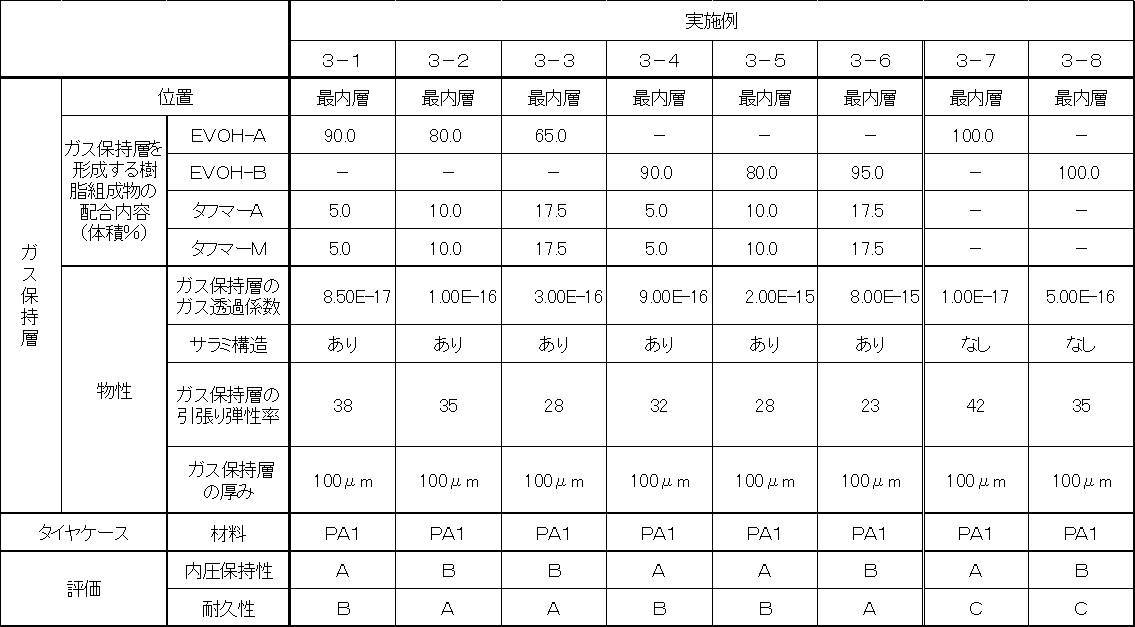
・EVOH-A: クラレ社製「エバール L-101」
(エチレン含有量27mol%、融点191℃、ガラス転移点72℃)
・EVOH-B: クラレ社製「エバール G-156」
(エチレン含量47mol% 融点157℃ ガラス転移点50℃)
・タフマーA:三井化学社製「タフマー A1050」
(未変性αオレフィンエラストマー、ガラス転移点-70℃)
・タフマーM:三井化学社製「タフマー MH7010」
(未変性αオレフィンエラストマー、ガラス転移点-65℃)
・PA1:ポリアミド系熱可塑性エラストマー(宇部興産(株)製「UBESTA XPA9055X1」、融点162℃)
・ガス透過係数(単位):cm3・cm/(cm2・s・Pa)
・引張弾性率(単位):MPa
Claims (21)
- 少なくとも樹脂材料で形成され且つ積層構造を有する環状のタイヤ骨格体を有し、前記タイヤ骨格体は、ガス保持層を少なくとも一層含むタイヤ。
- 前記ガス保持層は、80℃におけるガス透過係数が2.0×10⁻¹⁵cm3・cm/(cm2・s・Pa)以下のガス保持層である請求項1に記載のタイヤ。
- 前記ガス保持層は、熱可塑性樹脂を含む請求項1又は2に記載のタイヤ。
- 前記熱可塑性樹脂が、ポリアミド系熱可塑性樹脂又はエチレン-ビニルアルコール共重合体(EVOH)である請求項3に記載のタイヤ。
- 前記ガス保持層の4%引張り伸張時の応力が70MPa以下である請求項1~4のいずれか1項に記載のタイヤ。
- 前記ガス保持層は、ポリアミド系熱可塑性樹脂とエラストマーとからなる樹脂組成物を含む80℃におけるガス透過係数が2.0×10⁻¹⁴cm3・cm/(cm2・s・Pa)以下のガス保持層である請求項1に記載のタイヤ。
- 前記ポリアミド系熱可塑性樹脂に対する前記エラストマーの含有率が10~48体積%である請求項6に記載のタイヤ。
- 前記エラストマーは、熱可塑性エラストマーである請求項6又は7に記載のタイヤ。
- 前記熱可塑性エラストマーは、ポリオレフィン系熱可塑性エラストマーである請求項7に記載のタイヤ。
- 前記ガス保持層の4%引張伸張時における応力が50MPa以下である請求項6~9のいずれか1項に記載のタイヤ。
- 前記エラストマーは、変性エラストマー、又は、変性エラストマーと未変性エラストマーとの混合物である請求項6~10のいずれか1項に記載のタイヤ。
- 前記ガス保持層は、海相が前記ポリアミド系熱可塑性樹脂であり、島相が前記エラストマーであり、かつ、前記エラストマーの島相中に前記ポリアミド系熱可塑性樹脂が散点状に分散されて構成されている請求項6~11のいずれか1項に記載のタイヤ。
- 前記ガス保持層は、エチレン-ビニルアルコール共重合体と、エラストマーと、を含むガス保持層である請求項1に記載のタイヤ。
- 前記エチレン-ビニルアルコール共重合体に対する前記エラストマーの含有率が10~48質量%である請求項13に記載のタイヤ。
- 前記エラストマーは、熱可塑性エラストマーである請求項13又は14に記載のタイヤ。
- 前記熱可塑性エラストマーは、ポリオレフィン系熱可塑性エラストマーである請求項15に記載のタイヤ。
- 前記ガス保持層の4%引張り伸張時における応力が40MPa以下である請求項13~16のいずれか1項に記載のタイヤ。
- 前記エラストマーは、変性エラストマー、又は、変性エラストマーと未変性エラストマーとの混合物である請求項13~17のいずれか1項に記載のタイヤ。
- 前記ガス保持層は、海相が前記エチレン-ビニルアルコール共重合体であり、島相が前記エラストマーであり、かつ、前記エラストマーの島相中に前記エチレン-ビニルアルコール共重合体が散点状に分散されて構成されている請求項13~18のいずれか1項に記載のタイヤ。
- 前記タイヤ骨格体を形成する前記樹脂材料が、熱可塑性樹脂である請求項1~19のいずれか1項に記載のタイヤ。
- 前記熱可塑性樹脂が、熱可塑性エラストマーである請求項20に記載のタイヤ。
Priority Applications (5)
| Application Number | Priority Date | Filing Date | Title |
|---|---|---|---|
| RU2014136807/11A RU2582521C2 (ru) | 2012-02-14 | 2013-02-14 | Шина |
| US14/378,110 US10596853B2 (en) | 2012-02-14 | 2013-02-14 | Tire |
| BR112014020182A BR112014020182A8 (pt) | 2012-02-14 | 2013-02-14 | Pneu |
| EP13749835.8A EP2815894B1 (en) | 2012-02-14 | 2013-02-14 | Tire |
| CN201380009304.8A CN104125887B (zh) | 2012-02-14 | 2013-02-14 | 轮胎 |
Applications Claiming Priority (6)
| Application Number | Priority Date | Filing Date | Title |
|---|---|---|---|
| JP2012029914A JP5905289B2 (ja) | 2012-02-14 | 2012-02-14 | タイヤ |
| JP2012-029913 | 2012-02-14 | ||
| JP2012-029912 | 2012-02-14 | ||
| JP2012029912A JP5844173B2 (ja) | 2012-02-14 | 2012-02-14 | タイヤ |
| JP2012-029914 | 2012-02-14 | ||
| JP2012029913A JP5911731B2 (ja) | 2012-02-14 | 2012-02-14 | タイヤ |
Publications (1)
| Publication Number | Publication Date |
|---|---|
| WO2013122157A1 true WO2013122157A1 (ja) | 2013-08-22 |
Family
ID=48984266
Family Applications (1)
| Application Number | Title | Priority Date | Filing Date |
|---|---|---|---|
| PCT/JP2013/053553 WO2013122157A1 (ja) | 2012-02-14 | 2013-02-14 | タイヤ |
Country Status (5)
| Country | Link |
|---|---|
| US (1) | US10596853B2 (ja) |
| EP (1) | EP2815894B1 (ja) |
| BR (1) | BR112014020182A8 (ja) |
| RU (1) | RU2582521C2 (ja) |
| WO (1) | WO2013122157A1 (ja) |
Cited By (2)
| Publication number | Priority date | Publication date | Assignee | Title |
|---|---|---|---|---|
| JP2017013681A (ja) * | 2015-07-02 | 2017-01-19 | 株式会社ブリヂストン | タイヤ |
| US20170210171A1 (en) * | 2014-07-30 | 2017-07-27 | Bridgestone Corporation | Tire |
Families Citing this family (3)
| Publication number | Priority date | Publication date | Assignee | Title |
|---|---|---|---|---|
| EP2821251B1 (en) * | 2012-02-29 | 2017-05-03 | Bridgestone Corporation | Tire |
| US20190061423A1 (en) * | 2016-02-22 | 2019-02-28 | Bridgestone Corporation | Tire |
| CN109219632B (zh) * | 2016-05-31 | 2022-03-01 | 株式会社可乐丽 | 膜、成型体和膜的制造方法 |
Citations (9)
| Publication number | Priority date | Publication date | Assignee | Title |
|---|---|---|---|---|
| JPS5331256A (en) | 1976-09-04 | 1978-03-24 | Oval Eng Co Ltd | Fluid stirring method and apparatus therefor |
| JPH03143701A (ja) | 1989-10-27 | 1991-06-19 | Sumitomo Rubber Ind Ltd | 空気入りタイヤ |
| JPH04107104U (ja) * | 1983-02-16 | 1992-09-16 | ミシユラン、エ、コンパニー、(コンパニー、ゼネラール、デ、ゼタブリスマン、ミシユラン) | タイヤ用強化プライ |
| JP2003104008A (ja) | 2001-09-28 | 2003-04-09 | Yokohama Rubber Co Ltd:The | 空気入りタイヤ |
| JP2004346273A (ja) | 2003-05-26 | 2004-12-09 | Ube Ind Ltd | ポリアミド系エラストマー及びその製造方法 |
| JP2012006452A (ja) * | 2010-06-23 | 2012-01-12 | Yokohama Rubber Co Ltd:The | 空気入りタイヤ |
| JP2012029912A (ja) | 2010-07-30 | 2012-02-16 | Fujifilm Corp | 光プローブ及び光断層画像化装置 |
| JP2012029914A (ja) | 2010-07-30 | 2012-02-16 | Terumo Corp | 輸液ポンプ |
| JP2012029913A (ja) | 2010-07-30 | 2012-02-16 | Terumo Corp | 輸液ポンプ |
Family Cites Families (29)
| Publication number | Priority date | Publication date | Assignee | Title |
|---|---|---|---|---|
| DE3508544A1 (de) * | 1985-03-09 | 1986-09-18 | LIM Kunststoff-Technologie GmbH, Kittsee, Burgenland | Luftreifen aus kunststoffelastomeren, insbesondere gegossenen oder gespritzten polyurethanen |
| JP2704096B2 (ja) * | 1992-06-19 | 1998-01-26 | 横浜ゴム株式会社 | ホース |
| JPH1025375A (ja) | 1996-07-12 | 1998-01-27 | Yokohama Rubber Co Ltd:The | 熱可塑性エラストマー組成物及びこれを使用した空気入りタイヤ、ホース |
| KR100272125B1 (ko) | 1996-05-29 | 2000-11-15 | 하기와라 세이지 | 저투과성 열가소성 엘라스토머 조성물을 기체 투과 방지층에 사용하는 공기 주입 타이어 및 이에 사용하는 열가소성 엘라스토머 조성물 |
| JP4942253B2 (ja) | 2000-04-11 | 2012-05-30 | 横浜ゴム株式会社 | 加工性が改良された熱可塑性エラストマー組成物およびそれを用いたタイヤ |
| US6617383B2 (en) * | 2000-04-11 | 2003-09-09 | The Yokohama Rubber Co., Ltd. | Thermoplastic elastomer composition having improved processability and tire using the same |
| JP4696432B2 (ja) * | 2001-09-28 | 2011-06-08 | マツダ株式会社 | 熱可塑性樹脂組成物及び該組成物から成形された熱可塑性樹脂成形品並びに該成形品の製造方法 |
| US20060036033A1 (en) * | 2002-10-03 | 2006-02-16 | Katsunori Toyoshima | Thermoplastic saturated norbornene based resin film, and method for producing thermoplastic saturated norbornene based resin film |
| JP2006002130A (ja) | 2004-05-17 | 2006-01-05 | Bridgestone Corp | ポリアミド系複合樹脂及び冷媒輸送用ホース |
| KR101063972B1 (ko) * | 2004-06-24 | 2011-09-14 | 코오롱인더스트리 주식회사 | 공기 타이어의 이너라이너 |
| JP4629420B2 (ja) | 2004-12-03 | 2011-02-09 | 株式会社ブリヂストン | 積層体、その製造方法及びそれを用いたタイヤ |
| JP4972916B2 (ja) | 2005-05-31 | 2012-07-11 | 株式会社ブリヂストン | Evoh系複合樹脂及び冷媒輸送用ホース |
| JP4525824B2 (ja) * | 2006-03-03 | 2010-08-18 | 横浜ゴム株式会社 | 熱可塑性を示さないエラストマー組成物及びそれを用いた空気入りタイヤ |
| RU2429973C2 (ru) | 2006-10-26 | 2011-09-27 | Эксонмобил Кемикал Пэйтентс Инк. | Слоистая структура с малой влагопроницаемостью |
| EP2081765B1 (en) | 2006-10-26 | 2012-10-17 | ExxonMobil Chemical Patents Inc. | Low moisture permeability laminate construction |
| FR2916679B1 (fr) | 2007-05-29 | 2009-08-21 | Michelin Soc Tech | Objet pneumatique pourvu d'une couche etanche aux gaz a base d'un elastomere thermoplastique |
| JP5251347B2 (ja) | 2008-08-07 | 2013-07-31 | 横浜ゴム株式会社 | 熱可塑性エラストマー組成物並びにその製造方法及びそれを用いた空気入りタイヤ |
| JP4488097B2 (ja) | 2008-08-25 | 2010-06-23 | 横浜ゴム株式会社 | ガスバリア樹脂成形品または積層体 |
| EP2399760B1 (en) | 2009-02-17 | 2017-06-21 | Bridgestone Corporation | Tire manufacturing method |
| WO2010095654A1 (ja) | 2009-02-17 | 2010-08-26 | 株式会社ブリヂストン | タイヤ、及びタイヤの製造方法 |
| KR20110117708A (ko) | 2009-02-18 | 2011-10-27 | 가부시키가이샤 브리지스톤 | 타이어 |
| JP5419591B2 (ja) | 2009-08-20 | 2014-02-19 | 株式会社ブリヂストン | タイヤ、及びタイヤの製造方法。 |
| WO2011021526A1 (ja) | 2009-08-20 | 2011-02-24 | 株式会社ブリヂストン | タイヤの製造方法及びタイヤ |
| JP5336297B2 (ja) | 2009-08-20 | 2013-11-06 | 株式会社ブリヂストン | タイヤ、及び、タイヤの製造方法 |
| EP3002132A1 (en) | 2009-08-20 | 2016-04-06 | Bridgestone Corporation | Tire and tire manufacturing method |
| EP3251874B1 (en) | 2010-08-25 | 2019-02-20 | Bridgestone Corporation | Tire, and tire manufacturing method |
| JP5644332B2 (ja) * | 2010-09-29 | 2014-12-24 | 横浜ゴム株式会社 | 熱可塑性エラストマー組成物の製造方法 |
| JP6086643B2 (ja) | 2011-10-07 | 2017-03-01 | 株式会社ブリヂストン | タイヤ |
| JP5905298B2 (ja) | 2012-02-29 | 2016-04-20 | 株式会社ブリヂストン | タイヤ |
-
2013
- 2013-02-14 WO PCT/JP2013/053553 patent/WO2013122157A1/ja active Application Filing
- 2013-02-14 US US14/378,110 patent/US10596853B2/en active Active
- 2013-02-14 RU RU2014136807/11A patent/RU2582521C2/ru active
- 2013-02-14 EP EP13749835.8A patent/EP2815894B1/en active Active
- 2013-02-14 BR BR112014020182A patent/BR112014020182A8/pt active Search and Examination
Patent Citations (9)
| Publication number | Priority date | Publication date | Assignee | Title |
|---|---|---|---|---|
| JPS5331256A (en) | 1976-09-04 | 1978-03-24 | Oval Eng Co Ltd | Fluid stirring method and apparatus therefor |
| JPH04107104U (ja) * | 1983-02-16 | 1992-09-16 | ミシユラン、エ、コンパニー、(コンパニー、ゼネラール、デ、ゼタブリスマン、ミシユラン) | タイヤ用強化プライ |
| JPH03143701A (ja) | 1989-10-27 | 1991-06-19 | Sumitomo Rubber Ind Ltd | 空気入りタイヤ |
| JP2003104008A (ja) | 2001-09-28 | 2003-04-09 | Yokohama Rubber Co Ltd:The | 空気入りタイヤ |
| JP2004346273A (ja) | 2003-05-26 | 2004-12-09 | Ube Ind Ltd | ポリアミド系エラストマー及びその製造方法 |
| JP2012006452A (ja) * | 2010-06-23 | 2012-01-12 | Yokohama Rubber Co Ltd:The | 空気入りタイヤ |
| JP2012029912A (ja) | 2010-07-30 | 2012-02-16 | Fujifilm Corp | 光プローブ及び光断層画像化装置 |
| JP2012029914A (ja) | 2010-07-30 | 2012-02-16 | Terumo Corp | 輸液ポンプ |
| JP2012029913A (ja) | 2010-07-30 | 2012-02-16 | Terumo Corp | 輸液ポンプ |
Non-Patent Citations (1)
| Title |
|---|
| See also references of EP2815894A4 |
Cited By (3)
| Publication number | Priority date | Publication date | Assignee | Title |
|---|---|---|---|---|
| US20170210171A1 (en) * | 2014-07-30 | 2017-07-27 | Bridgestone Corporation | Tire |
| US10589571B2 (en) * | 2014-07-30 | 2020-03-17 | Bridgestone Corporation | Tire |
| JP2017013681A (ja) * | 2015-07-02 | 2017-01-19 | 株式会社ブリヂストン | タイヤ |
Also Published As
| Publication number | Publication date |
|---|---|
| EP2815894A1 (en) | 2014-12-24 |
| EP2815894A4 (en) | 2015-10-14 |
| US10596853B2 (en) | 2020-03-24 |
| RU2582521C2 (ru) | 2016-04-27 |
| BR112014020182A8 (pt) | 2017-07-11 |
| EP2815894B1 (en) | 2016-10-05 |
| US20150007921A1 (en) | 2015-01-08 |
| BR112014020182A2 (ja) | 2017-06-20 |
| RU2014136807A (ru) | 2016-04-10 |
| CN104125887A (zh) | 2014-10-29 |
Similar Documents
| Publication | Publication Date | Title |
|---|---|---|
| WO2013129525A1 (ja) | タイヤ | |
| JP6086643B2 (ja) | タイヤ | |
| JP6057981B2 (ja) | タイヤ | |
| WO2013129631A1 (ja) | タイヤ | |
| JP5818577B2 (ja) | タイヤ | |
| WO2013129627A1 (ja) | タイヤ | |
| WO2013129630A1 (ja) | タイヤ | |
| JP6138412B2 (ja) | タイヤ | |
| WO2013154205A1 (ja) | タイヤ | |
| WO2013122157A1 (ja) | タイヤ | |
| WO2013129632A1 (ja) | タイヤ | |
| JP5818578B2 (ja) | タイヤ | |
| JP5627954B2 (ja) | タイヤ | |
| JP5778402B2 (ja) | タイヤ | |
| JP5911731B2 (ja) | タイヤ | |
| JP5905298B2 (ja) | タイヤ | |
| JP5844173B2 (ja) | タイヤ | |
| JP6649766B2 (ja) | タイヤ | |
| JP6049273B2 (ja) | タイヤ | |
| JP6114498B2 (ja) | タイヤ | |
| JP5905289B2 (ja) | タイヤ | |
| JP5865732B2 (ja) | タイヤ | |
| JP5840534B2 (ja) | タイヤ | |
| JP2016035067A (ja) | タイヤ | |
| JP6014714B2 (ja) | タイヤ及びその製造方法 |
Legal Events
| Date | Code | Title | Description |
|---|---|---|---|
| 121 | Ep: the epo has been informed by wipo that ep was designated in this application |
Ref document number: 13749835 Country of ref document: EP Kind code of ref document: A1 |
|
| WWE | Wipo information: entry into national phase |
Ref document number: 14378110 Country of ref document: US |
|
| NENP | Non-entry into the national phase |
Ref country code: DE |
|
| REEP | Request for entry into the european phase |
Ref document number: 2013749835 Country of ref document: EP |
|
| WWE | Wipo information: entry into national phase |
Ref document number: 2013749835 Country of ref document: EP |
|
| WWE | Wipo information: entry into national phase |
Ref document number: 2014136807 Country of ref document: RU |
|
| REG | Reference to national code |
Ref country code: BR Ref legal event code: B01A Ref document number: 112014020182 Country of ref document: BR |
|
| ENP | Entry into the national phase |
Ref document number: 112014020182 Country of ref document: BR Kind code of ref document: A2 Effective date: 20140814 |