WO2013111739A1 - 車両の制御装置及び車両の制御方法 - Google Patents
車両の制御装置及び車両の制御方法 Download PDFInfo
- Publication number
- WO2013111739A1 WO2013111739A1 PCT/JP2013/051179 JP2013051179W WO2013111739A1 WO 2013111739 A1 WO2013111739 A1 WO 2013111739A1 JP 2013051179 W JP2013051179 W JP 2013051179W WO 2013111739 A1 WO2013111739 A1 WO 2013111739A1
- Authority
- WO
- WIPO (PCT)
- Prior art keywords
- control
- damping
- damping force
- control amount
- unsprung
- Prior art date
Links
Images


Classifications
-
- B—PERFORMING OPERATIONS; TRANSPORTING
- B60—VEHICLES IN GENERAL
- B60G—VEHICLE SUSPENSION ARRANGEMENTS
- B60G17/00—Resilient suspensions having means for adjusting the spring or vibration-damper characteristics, for regulating the distance between a supporting surface and a sprung part of vehicle or for locking suspension during use to meet varying vehicular or surface conditions, e.g. due to speed or load
- B60G17/015—Resilient suspensions having means for adjusting the spring or vibration-damper characteristics, for regulating the distance between a supporting surface and a sprung part of vehicle or for locking suspension during use to meet varying vehicular or surface conditions, e.g. due to speed or load the regulating means comprising electric or electronic elements
- B60G17/018—Resilient suspensions having means for adjusting the spring or vibration-damper characteristics, for regulating the distance between a supporting surface and a sprung part of vehicle or for locking suspension during use to meet varying vehicular or surface conditions, e.g. due to speed or load the regulating means comprising electric or electronic elements characterised by the use of a specific signal treatment or control method
-
- B—PERFORMING OPERATIONS; TRANSPORTING
- B60—VEHICLES IN GENERAL
- B60G—VEHICLE SUSPENSION ARRANGEMENTS
- B60G17/00—Resilient suspensions having means for adjusting the spring or vibration-damper characteristics, for regulating the distance between a supporting surface and a sprung part of vehicle or for locking suspension during use to meet varying vehicular or surface conditions, e.g. due to speed or load
- B60G17/015—Resilient suspensions having means for adjusting the spring or vibration-damper characteristics, for regulating the distance between a supporting surface and a sprung part of vehicle or for locking suspension during use to meet varying vehicular or surface conditions, e.g. due to speed or load the regulating means comprising electric or electronic elements
- B60G17/016—Resilient suspensions having means for adjusting the spring or vibration-damper characteristics, for regulating the distance between a supporting surface and a sprung part of vehicle or for locking suspension during use to meet varying vehicular or surface conditions, e.g. due to speed or load the regulating means comprising electric or electronic elements characterised by their responsiveness, when the vehicle is travelling, to specific motion, a specific condition, or driver input
- B60G17/0165—Resilient suspensions having means for adjusting the spring or vibration-damper characteristics, for regulating the distance between a supporting surface and a sprung part of vehicle or for locking suspension during use to meet varying vehicular or surface conditions, e.g. due to speed or load the regulating means comprising electric or electronic elements characterised by their responsiveness, when the vehicle is travelling, to specific motion, a specific condition, or driver input to an external condition, e.g. rough road surface, side wind
-
- B—PERFORMING OPERATIONS; TRANSPORTING
- B60—VEHICLES IN GENERAL
- B60G—VEHICLE SUSPENSION ARRANGEMENTS
- B60G17/00—Resilient suspensions having means for adjusting the spring or vibration-damper characteristics, for regulating the distance between a supporting surface and a sprung part of vehicle or for locking suspension during use to meet varying vehicular or surface conditions, e.g. due to speed or load
- B60G17/015—Resilient suspensions having means for adjusting the spring or vibration-damper characteristics, for regulating the distance between a supporting surface and a sprung part of vehicle or for locking suspension during use to meet varying vehicular or surface conditions, e.g. due to speed or load the regulating means comprising electric or electronic elements
- B60G17/0195—Resilient suspensions having means for adjusting the spring or vibration-damper characteristics, for regulating the distance between a supporting surface and a sprung part of vehicle or for locking suspension during use to meet varying vehicular or surface conditions, e.g. due to speed or load the regulating means comprising electric or electronic elements characterised by the regulation being combined with other vehicle control systems
-
- B—PERFORMING OPERATIONS; TRANSPORTING
- B60—VEHICLES IN GENERAL
- B60G—VEHICLE SUSPENSION ARRANGEMENTS
- B60G17/00—Resilient suspensions having means for adjusting the spring or vibration-damper characteristics, for regulating the distance between a supporting surface and a sprung part of vehicle or for locking suspension during use to meet varying vehicular or surface conditions, e.g. due to speed or load
- B60G17/06—Characteristics of dampers, e.g. mechanical dampers
-
- B—PERFORMING OPERATIONS; TRANSPORTING
- B60—VEHICLES IN GENERAL
- B60G—VEHICLE SUSPENSION ARRANGEMENTS
- B60G2400/00—Indexing codes relating to detected, measured or calculated conditions or factors
- B60G2400/10—Acceleration; Deceleration
- B60G2400/106—Acceleration; Deceleration longitudinal with regard to vehicle, e.g. braking
-
- B—PERFORMING OPERATIONS; TRANSPORTING
- B60—VEHICLES IN GENERAL
- B60G—VEHICLE SUSPENSION ARRANGEMENTS
- B60G2400/00—Indexing codes relating to detected, measured or calculated conditions or factors
- B60G2400/20—Speed
- B60G2400/204—Vehicle speed
-
- B—PERFORMING OPERATIONS; TRANSPORTING
- B60—VEHICLES IN GENERAL
- B60G—VEHICLE SUSPENSION ARRANGEMENTS
- B60G2400/00—Indexing codes relating to detected, measured or calculated conditions or factors
- B60G2400/20—Speed
- B60G2400/208—Speed of wheel rotation
-
- B—PERFORMING OPERATIONS; TRANSPORTING
- B60—VEHICLES IN GENERAL
- B60G—VEHICLE SUSPENSION ARRANGEMENTS
- B60G2400/00—Indexing codes relating to detected, measured or calculated conditions or factors
- B60G2400/30—Propulsion unit conditions
-
- B—PERFORMING OPERATIONS; TRANSPORTING
- B60—VEHICLES IN GENERAL
- B60G—VEHICLE SUSPENSION ARRANGEMENTS
- B60G2400/00—Indexing codes relating to detected, measured or calculated conditions or factors
- B60G2400/30—Propulsion unit conditions
- B60G2400/32—Torque on propulsion shaft
-
- B—PERFORMING OPERATIONS; TRANSPORTING
- B60—VEHICLES IN GENERAL
- B60G—VEHICLE SUSPENSION ARRANGEMENTS
- B60G2400/00—Indexing codes relating to detected, measured or calculated conditions or factors
- B60G2400/30—Propulsion unit conditions
- B60G2400/33—Throttle position
-
- B—PERFORMING OPERATIONS; TRANSPORTING
- B60—VEHICLES IN GENERAL
- B60G—VEHICLE SUSPENSION ARRANGEMENTS
- B60G2400/00—Indexing codes relating to detected, measured or calculated conditions or factors
- B60G2400/30—Propulsion unit conditions
- B60G2400/39—Brake pedal position
-
- B—PERFORMING OPERATIONS; TRANSPORTING
- B60—VEHICLES IN GENERAL
- B60G—VEHICLE SUSPENSION ARRANGEMENTS
- B60G2400/00—Indexing codes relating to detected, measured or calculated conditions or factors
- B60G2400/40—Steering conditions
- B60G2400/41—Steering angle
-
- B—PERFORMING OPERATIONS; TRANSPORTING
- B60—VEHICLES IN GENERAL
- B60G—VEHICLE SUSPENSION ARRANGEMENTS
- B60G2500/00—Indexing codes relating to the regulated action or device
- B60G2500/10—Damping action or damper
Definitions
- the present invention relates to a control device that controls the state of a vehicle.
- Patent Document 1 A technique described in Patent Document 1 is disclosed as a technique related to a vehicle control device. This publication discloses a technique for controlling the sprung posture using a suspension control device capable of changing the damping force.
- the present invention has been made paying attention to the above problem, and an object of the present invention is to provide a vehicle control device capable of controlling the vehicle body posture while reducing the uncomfortable feeling to the passenger.
- the vehicle control apparatus of the present invention calculates a damping force control amount based on the larger control amount of the sprung mass damping control amount and the unsprung vibration damping control amount, It was decided to control the damping force of the variable force shock absorber.
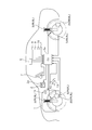
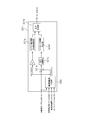
- FIG. 1 is a system schematic diagram illustrating a vehicle control apparatus according to a first embodiment.
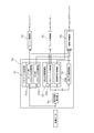
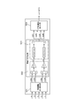
- FIG. 2 is a control block diagram illustrating a control configuration of the vehicle control device according to the first embodiment.
- FIG. 3 is a control block diagram illustrating a configuration of roll rate suppression control according to the first embodiment. 3 is a time chart illustrating an envelope waveform forming process of roll rate suppression control according to the first embodiment.
- FIG. 3 is a control block diagram illustrating a configuration of a traveling state estimation unit according to the first embodiment. It is a control block diagram showing the control content in the stroke speed calculating part of Example 1.
- FIG. 3 is a block diagram illustrating a configuration of a reference wheel speed calculation unit according to the first embodiment. It is the schematic showing a vehicle body vibration model.
- FIG. 6 is a control block diagram illustrating actuator control amount calculation processing when performing pitch control according to the first embodiment. It is a control block diagram showing brake pitch control of Example 1. It is the figure which expressed simultaneously the wheel speed frequency characteristic detected by the wheel speed sensor, and the stroke frequency characteristic of the stroke sensor which is not mounted in the Example. It is a control block diagram showing the frequency sensitive control in the sprung mass damping control of the first embodiment. It is a correlation diagram showing the human sensory characteristic in each frequency domain. It is a characteristic view showing the relationship between the vibration mixing ratio of the wing area
- FIG. 3 is a block diagram illustrating a control configuration of unsprung vibration suppression control according to the first embodiment.
- FIG. 3 is a control block diagram illustrating a control configuration of a damping force control unit according to the first embodiment.
- 6 is a flowchart illustrating attenuation coefficient arbitration processing in a standard mode according to the first embodiment.
- 6 is a flowchart illustrating an attenuation coefficient arbitration process in the sport mode according to the first embodiment.
- 6 is a flowchart illustrating attenuation coefficient arbitration processing in the comfort mode according to the first embodiment.
- 6 is a flowchart illustrating attenuation coefficient arbitration processing in a highway mode according to the first exemplary embodiment.
- FIG. 6 is a flowchart illustrating a mode selection process based on a running state in an attenuation coefficient arbitration unit according to the first embodiment.
- FIG. 1 is a system schematic diagram illustrating a vehicle control apparatus according to the first embodiment.
- the vehicle includes an engine 1 that is a power source and a brake 20 that generates braking torque due to friction force on each wheel (hereinafter, when displaying brakes corresponding to individual wheels, right front wheel brake: 20FR, left front wheel brake: 20FL).
- S / A shock absorber 3
- the engine 1 includes an engine controller (hereinafter also referred to as an engine control unit, which corresponds to power source control means) 1a that controls torque output from the engine 1, and the engine controller 1a is configured to By controlling the fuel injection amount, ignition timing, etc., the desired engine operating state (engine speed and engine output torque) is controlled. Further, the brake 20 generates a braking torque based on the hydraulic pressure supplied from the brake control unit 2 that can control the brake hydraulic pressure of each wheel according to the traveling state.
- the brake control unit 2 includes a brake controller (hereinafter also referred to as a brake control unit) 2a for controlling a braking torque generated by the brake 20, and a master cylinder pressure generated by a driver's brake pedal operation or a built-in motor.
- a pump pressure generated by the drive pump is used as a hydraulic pressure source, and a desired hydraulic pressure is generated in the brake 20 of each wheel by opening and closing operations of a plurality of solenoid valves.
- the S / A3 is a damping force generator that attenuates the elastic motion of a coil spring provided between a vehicle unsprung (axle, wheel, etc.) and a sprung (vehicle body, etc.). It is configured to be variable.
- the S / A 3 includes a cylinder in which fluid is sealed, a piston that strokes in the cylinder, and an orifice that controls fluid movement between fluid chambers formed above and below the piston. Furthermore, orifices having a plurality of types of orifice diameters are formed in the piston, and an orifice corresponding to a control command is selected from the plurality of types of orifices when the S / A actuator is operated. Thereby, the damping force according to the orifice diameter can be generated. For example, if the orifice diameter is small, the movement of the piston is easily restricted, so that the damping force is high. If the orifice diameter is large, the movement of the piston is difficult to be restricted, and thus the damping force is small.
- an electromagnetic control valve is arranged on the communication path connecting fluids formed above and below the piston, and the damping force is set by controlling the opening / closing amount of the electromagnetic control valve.
- the S / A 3 has an S / A controller 3a (corresponding to damping force control means) that controls the damping force of the S / A 3, and controls the damping force by operating the orifice diameter by the S / A actuator.
- a wheel speed sensor 5 for detecting the wheel speed of each wheel (hereinafter, when displaying wheel speeds corresponding to individual wheels, right front wheel speed: 5FR, left front wheel speed: 5FL, right rear wheel speed: 5RR). , Left rear wheel speed: 5RL)), an integrated sensor 6 for detecting longitudinal acceleration, yaw rate and lateral acceleration acting on the center of gravity of the vehicle, and a steering angle which is a steering operation amount of the driver is detected.
- Steering angle sensor 7 vehicle speed sensor 8 for detecting vehicle speed
- engine torque sensor 9 for detecting engine torque
- engine speed sensor 10 for detecting engine speed
- master pressure sensor 11 for detecting master cylinder pressure.
- a brake switch 12 that outputs an on-state signal when a brake pedal operation is performed
- an accelerator opening sensor 13 that detects an accelerator pedal opening.
- the signals of these various sensors are input to the S / A controller 3a.
- the arrangement of the integrated sensor 6 may be at the center of gravity of the vehicle, or may be any place other than that as long as various values at the center of gravity can be estimated. Moreover, it is not necessary to be an integral type, and a configuration in which yaw rate, longitudinal acceleration, and lateral acceleration are individually detected may be employed.
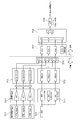
- FIG. 2 is a control block diagram showing the control configuration of the vehicle control apparatus according to the first embodiment.
- the controller is composed of an engine controller 1a, a brake controller 2a, and an S / A controller 3a.
- a driver input control unit 31 for performing driver input control for achieving a desired vehicle posture based on driver operations (steering operation, accelerator operation, brake pedal operation, etc.), and various sensors.
- a traveling state estimating unit 32 that estimates the traveling state based on the detected value
- a sprung mass damping control unit 33 that controls the vibration state on the spring based on the estimated traveling state, and the like.
- An unsprung vibration suppression control unit 34 that controls the unsprung vibration state, a shock absorber posture control amount output from the driver input control unit 31, and an unsprung vibration suppression control amount output from the sprung vibration suppression control unit 33. Based on the unsprung vibration suppression control amount output from the unsprung vibration suppression control unit 34, a damping force to be set in the S / A 3 is determined, and the damping force control unit 3 that performs the S / A damping force control. With the door.
- the damping force control unit 35 is excluded from the S / A controller 3a and used as an attitude control controller, and the damping force control unit 35 is configured as an S / A controller.
- the A controller may be configured to include four controllers, or each controller may be configured from one integrated controller without particular limitation.
- the engine controller and the brake controller in the existing vehicle are used as they are as the engine control unit 1a and the brake control unit 2a, and the S / A controller 3a is separately installed. It is assumed that the vehicle control apparatus according to the first embodiment is realized.
- the control amount by the engine 1 and the brake 20 is limited and output from the control amount that can be actually output, thereby reducing the burden on the S / A 3 and accompanying the control of the engine 1 and the brake 20. Suppresses discomfort that occurs.
- Skyhook control is performed by all actuators. At this time, without using a stroke sensor or a sprung vertical acceleration sensor generally required for skyhook control, the skyhook control can be performed with an inexpensive configuration using wheel speed sensors mounted on all vehicles. Realize.
- scalar control frequency sensitive control
- the driver input control unit 31 achieves the vehicle posture required by the driver by the engine side driver input control unit 31a that achieves the vehicle posture required by the driver by torque control of the engine 1 and the damping force control of S / A3. And an S / A side driver input control unit 31b.
- the vehicle behavior desired to be achieved by the driver is determined based on the ground load variation suppression control amount that suppresses the ground load variation of the front wheels and the rear wheels, and signals from the steering angle sensor 7 and the vehicle speed sensor 8.
- the corresponding yaw response control amount is calculated and output to the engine control unit 1a.
- the S / A-side driver input control unit 31b calculates a driver input damping force control amount corresponding to the vehicle behavior that the driver wants to achieve based on signals from the steering angle sensor 7 and the vehicle speed sensor 8, and the damping force control unit 35 Output for. For example, when the driver is turning, if the nose side of the vehicle is lifted, the driver's field of view easily deviates from the road surface. In this case, the four-wheel damping force is used as a driver input damping force to prevent the nose from rising. Output as a controlled variable. In addition, a driver input damping force control amount that suppresses a roll generated during turning is output.
- FIG. 3 is a control block diagram illustrating a configuration of roll rate suppression control according to the first embodiment.
- the lateral acceleration estimation unit 31b1 the front wheel rudder angle ⁇ f detected by the rudder angle sensor 7 and the rear wheel rudder angle ⁇ r (the actual rear wheel rudder angle if a rear wheel steering device is provided, and 0 in other cases as appropriate)
- the lateral acceleration Yg is estimated based on the vehicle speed VSP detected by the vehicle speed sensor 8. This lateral acceleration Yg is calculated by the following equation using the yaw rate estimated value ⁇ .
- Yg VSP ⁇ ⁇
- the yaw rate estimated value ⁇ is calculated by the following equation.
- the 90 ° phase advance component creation unit 31b2 differentiates the estimated lateral acceleration Yg and outputs a lateral acceleration differential value dYg.
- the 90 ° phase delay component creation unit 31b3 outputs a component F (dYg) obtained by delaying the phase of the lateral acceleration differential value dYg by 90 °.
- the component F (dYg) is obtained by returning the phase of the component from which the low-frequency region has been removed by the 90 ° phase advance component creation unit 31b2 to the phase of the lateral acceleration Yg. It is a transient component of acceleration Yg.
- the 90 ° phase delay component creation unit 31b4 outputs a component F (Yg) obtained by delaying the phase of the estimated lateral acceleration Yg by 90 °.
- the gain multiplication unit 31b5 multiplies the lateral acceleration Yg, the lateral acceleration differential value dYg, the lateral acceleration DC cut component F (dYg), and the 90 ° phase delay component F (Yg) by a gain. Each gain is set based on a roll rate transfer function with respect to the steering angle. Each gain may be adjusted according to four control modes described later.
- the square calculator 31b6 squares and outputs each component multiplied by the gain.
- the combining unit 31b7 adds the values output from the square calculation unit 31b6.
- the gain multiplication unit 31b8 multiplies the square value of each added component by the gain and outputs the result.
- the square root calculation unit 31b9 calculates a driver input attitude control amount for roll rate suppression control by calculating the square root of the value output from the gain multiplication unit 31b7, and outputs the calculated value to the damping force control unit 35.
- 90 ° phase advance component creation unit 31b2, 90 ° phase lag component creation unit 31b3, 90 ° phase lag component creation unit 31b4, gain multiplication unit 31b5, square operation unit 31b6, synthesis unit 31b7, gain multiplication unit 31b8, square root operation unit 31b9 Corresponds to the Hilbert transform unit 31b10 that generates an envelope waveform using the Hilbert transform.
- FIG. 4 is a time chart showing an envelope waveform forming process of roll rate suppression control according to the first embodiment.
- the driver starts steering at time t1
- roll rate begins to gradually occur.
- the 90 ° phase advance component dYg is added to form an envelope waveform
- the driver input attitude control amount is calculated based on the scalar amount based on the envelope waveform, thereby suppressing the occurrence of roll rate in the initial stage of steering.
- Can do Furthermore, by adding the lateral acceleration DC cut component F (dYg) to form an envelope waveform, it effectively suppresses the roll rate that occurs in a transitional state when the driver starts or ends steering. Can do.
- phase delay component F (Yg) If the phase delay component F (Yg) is not added, the damping force from the time t2 to the time t3 is set to a small value, which may cause the vehicle behavior to become unstable due to the roll rate resonance component. In order to suppress this roll rate resonance component, a 90 ° phase delay component F (Yg) is added.
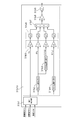
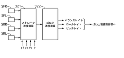
- FIG. 5 is a control block diagram illustrating the configuration of the traveling state estimation unit according to the first embodiment.
- the traveling state estimation unit 32 of the first embodiment basically, based on the wheel speed detected by the wheel speed sensor 5, the stroke speed of each wheel used for the skyhook control of the sprung mass damping control unit 33 described later, Calculate bounce rate, roll rate and pitch rate.
- the value of the wheel speed sensor 5 of each wheel is input to the stroke speed calculation unit 321, and the sprung speed is calculated from the stroke speed of each wheel calculated by the stroke speed calculation unit 321.
- FIG. 6 is a control block diagram showing the control contents in the stroke speed calculation unit of the first embodiment.
- the stroke speed calculation unit 321 is individually provided for each wheel, and the control block diagram shown in FIG. 6 is a control block diagram focusing on a certain wheel.
- the value of the wheel speed sensor 5, the front wheel steering angle ⁇ f detected by the steering angle sensor 7, and the rear wheel steering angle ⁇ r (actual rear wheel steering if a rear wheel steering device is provided).
- the reference wheel speed calculation unit 300 that calculates a reference wheel speed based on the vehicle body lateral speed and the actual yaw rate detected by the integrated sensor 6, and the angle may be appropriately set to 0 in other cases.
- a tire rotation vibration frequency calculation unit 321a that calculates the tire rotation vibration frequency based on the calculated reference wheel speed, and a deviation calculation unit 321b that calculates a deviation (wheel speed fluctuation) between the reference wheel speed and the wheel speed sensor value.
- a GEO conversion unit 321c that converts the deviation calculated by the deviation calculation unit 321b into a suspension stroke amount, a stroke speed calibration unit 321d that calibrates the converted stroke amount to a stroke speed,
- a band elimination filter corresponding to the frequency calculated by the tire rotation vibration frequency calculation unit 321a is applied to the value calibrated by the roke speed calibration unit 321d to remove the tire rotation primary vibration component and calculate the final stroke speed.
- a signal processing unit 321e that calculates the tire rotation vibration frequency based on the calculated reference wheel speed
- a deviation calculation unit 321b that calculates a deviation (wheel speed fluctuation) between the reference wheel speed and the wheel speed sensor value.
- a GEO conversion unit 321c that converts the deviation calculated by the deviation calculation unit 321b
- FIG. 7 is a block diagram illustrating a configuration of a reference wheel speed calculation unit according to the first embodiment.
- the reference wheel speed refers to a value obtained by removing various disturbances from each wheel speed.
- the difference between the wheel speed sensor value and the reference wheel speed is a value related to a component that fluctuates according to the stroke generated by the bounce behavior, roll behavior, pitch behavior, or unsprung vertical vibration of the vehicle body.
- the stroke speed is estimated based on this difference.
- the plane motion component extraction unit 301 calculates the first wheel speed V0 that is the reference wheel speed of each wheel based on the vehicle body plan view model with the wheel speed sensor value as an input.
- the wheel speed sensor value detected by the wheel speed sensor 5 is ⁇ (rad / s)
- the front wheel actual steering angle detected by the steering angle sensor 7 is ⁇ f (rad)
- the rear wheel actual steering angle is ⁇ r (rad )
- the vehicle body lateral speed is Vx
- the yaw rate detected by the integrated sensor 6 is ⁇ (rad / s)
- the vehicle speed estimated from the calculated reference wheel speed ⁇ 0 is V (m / s)
- the reference to be calculated Wheel speed is VFL, VFR, VRL, VRR
- front wheel tread is Tf
- rear wheel tread is Tr
- distance from vehicle center of gravity to front wheel is Lf
- distance from vehicle center of gravity to rear wheel is Lr.
- VFL (V-Tf / 2 ⁇ ⁇ ) cos ⁇ f + (Vx + Lf ⁇ ⁇ ) sin ⁇ f
- VFR (V + Tf / 2 ⁇ ⁇ ) cos ⁇ f + (Vx + Lf ⁇ ⁇ ) sin ⁇ f
- VRL (V ⁇ Tr / 2 ⁇ ⁇ ) cos ⁇ r + (Vx ⁇ Lr ⁇ ⁇ ) sin ⁇ r
- VRR (V + Tr / 2 ⁇ ⁇ ) cos ⁇ r + (Vx-Lr ⁇ ⁇ ) sin ⁇ r
- V is described as V0FL, V0FR, V0RL, V0RR (corresponding to the first wheel speed) as a value corresponding to each wheel.
- V0FL ⁇ VFL-Lf ⁇ ⁇ sin ⁇ f ⁇ / cos ⁇ f + Tf / 2 ⁇ ⁇
- V0FR ⁇ VFR-Lf ⁇ ⁇ sin ⁇ f ⁇ / cos ⁇ f-Tf / 2 ⁇ ⁇
- V0RL ⁇ VRL + Lr ⁇ ⁇ sin ⁇ r ⁇ / cos ⁇ r + Tr / 2 ⁇ ⁇
- V0RR ⁇ VRR + Lf ⁇ ⁇ sin ⁇ f ⁇ / cos ⁇ r-Tr / 2 ⁇ ⁇
- the roll disturbance removing unit 302 calculates the second wheel speeds V0F and V0R as the reference wheel speeds for the front and rear wheels based on the vehicle body front view model with the first wheel speed V0 as an input.
- the vehicle body front view model removes the wheel speed difference caused by the roll motion that occurs around the roll rotation center on the vertical line passing through the center of gravity of the vehicle when the vehicle is viewed from the front. Is done.
- V0F (V0FL + V0FR) / 2
- V0R (V0RL + V0RR) / 2
- the second wheel speeds V0F and V0R from which disturbance based on the roll is removed are obtained.
- the pitch disturbance removal unit 303 calculates the third wheel speeds VbFL, VbFR, VbRL, and VbRR, which are the reference wheel speeds for all the wheels, based on the vehicle side view model, with the second wheel speeds V0F and V0R as inputs.
- the vehicle body side view model is to remove the wheel speed difference caused by the pitch motion generated around the pitch rotation center on the vertical line passing through the center of gravity of the vehicle when the vehicle is viewed from the lateral direction. It is expressed by the following formula.
- the sprung speed calculation unit 322 calculates the bounce rate, roll rate, and pitch rate for skyhook control. Calculated.
- Skyhook control is to achieve a flat running state by setting a damping force based on the relationship between the S / A3 stroke speed and the sprung speed, and controlling the posture on the sprung.
- the value that can be detected from the wheel speed sensor 5 is the stroke speed, and since the vertical acceleration sensor or the like is not provided on the spring, the sprung speed needs to be estimated using an estimation model.
- the problem of the estimation model and the model configuration to be adopted will be described.
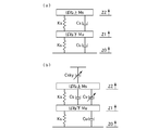
- FIG. 8 is a schematic diagram showing a vehicle body vibration model.
- FIG. 8A is a model of a vehicle (hereinafter referred to as a “convex vehicle”) having an S / A having a constant damping force
- FIG. 8B has an S / A having a variable damping force.
- Ms represents the mass above the spring
- Mu represents the mass below the spring
- Ks represents the elastic coefficient of the coil spring
- Cs represents the damping coefficient of S / A
- Ku represents the unsprung (tire).
- Cu represents an unsprung (tire) damping coefficient
- Cv represents a variable damping coefficient
- Z2 represents a position on the spring
- z1 represents a position under the spring
- z0 represents a road surface position.
- Changing the damping force basically means changing the force that limits the piston moving speed of S / A 3 in accordance with the suspension stroke. Since the semi-active S / A3 that cannot positively move the piston in the desired direction is used, when the semi-active skyhook model is employed and the sprung speed is obtained, it is expressed as follows.
- the magnitude of the estimated sprung speed is smaller than the actual value in the frequency band below the sprung resonance, but the most important in skyhook control is the phase. If the correspondence between the phase and the sign can be maintained, the skyhook can be maintained. Since control is achieved and the magnitude of the sprung speed can be adjusted by other factors, there is no problem.
- the sprung speed can be estimated if the stroke speed of each wheel is known.
- the actual vehicle is four wheels instead of one wheel, it is considered to estimate the state of the spring by mode decomposition into roll rate, pitch rate and bounce rate using the stroke speed of each wheel. To do.
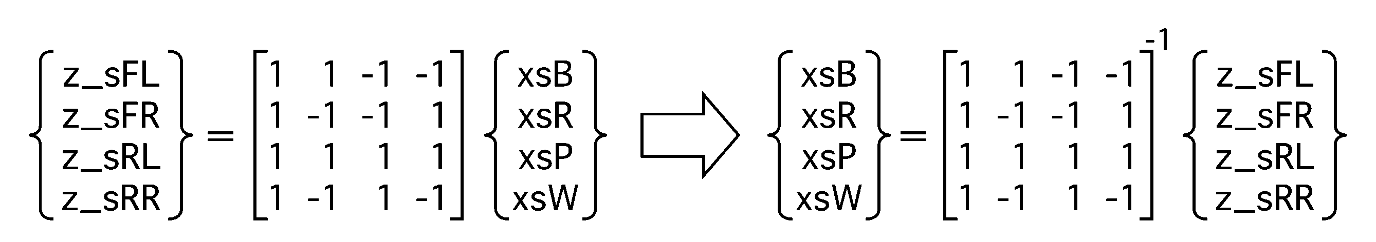
- the above three components are calculated from the stroke speed of the four wheels, one corresponding component is insufficient, and the solution becomes indefinite. Therefore, a war plate representing the movement of the diagonal wheels is introduced.
- the stroke amount bounce term is xsB
- the roll term is xsR
- the pitch term is xsP
- the warp term is xsW
- the stroke amount corresponding to Vz_sFL, Vz_sFR, Vz_sRL, Vz_sRR is z_sFL, z_sFR, z_sRL, z_sRR, Holds.
- dxsB 1/4 (Vz_sFL + Vz_sFR + Vz_sRL + Vz_sRR)
- dxsR 1/4 (Vz_sFL-Vz_sFR + Vz_sRL-Vz_sRR)
- dxsP 1/4 (-Vz_sFL-Vz_sFR + Vz_sRL + Vz_sRR)
- dxsW 1/4 (-Vz_sFL + Vz_sFR + Vz_sRL-Vz_sRR)
- the sprung mass damping control unit 33 includes a skyhook control unit 33a that performs posture control based on the above-described sprung speed estimation value, and a frequency response that suppresses sprung vibration based on the road surface input frequency. And a control unit 33b.
- the vehicle control apparatus includes the engine 1, the brake 20, and the S / A 3 as actuators for achieving sprung posture control.
- the skyhook control unit 33a controls bounce rate, roll rate, and pitch rate for S / A3, controls bounce rate and pitch rate for engine 1, and controls pitch for brake 20. The rate is controlled.
- the control amount for each actuator can be determined by using the sprung speed estimated by the traveling state estimation unit 32 described above.
- FB is transmitted to the engine 1 and S / A 3 as a bounce attitude control amount
- FR is a control executed only at S / A 3, and thus is transmitted to the damping force control unit 35 as a roll attitude control amount.
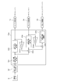
- FIG. 9 is a control block diagram illustrating actuator control amount calculation processing when performing pitch control according to the first embodiment.
- the skyhook control unit 33a is achieved by the engine 1 and the first target attitude control amount calculation unit 331 that calculates a target pitch rate that is a first target attitude control amount that is a control amount that can be used in common for all actuators.
- the first target attitude control amount calculation unit 331 outputs the pitch rate as it is (hereinafter, this pitch rate is referred to as the pitch rate). It is described as a first target attitude control amount.)
- the engine attitude control amount calculation unit 332 calculates an engine attitude control amount that is a control amount that can be achieved by the engine 1 based on the input first target attitude control amount.
- a limit value for limiting the engine torque control amount according to the engine attitude control amount is set in order not to give the driver a sense of incongruity.
- the engine torque control amount is limited to be within a predetermined longitudinal acceleration range when converted to longitudinal acceleration. Therefore, if the engine torque control amount is calculated based on the first target attitude control amount and a value equal to or greater than the limit value is calculated, the pitch rate skyhook control amount that can be achieved by the limit value (suppressed by the engine 1).
- a value obtained by multiplying the pitch rate by CskyP hereinafter referred to as an engine attitude control amount
- the value converted into the pitch rate in the conversion unit 332a is output to the second target attitude control amount calculation unit 333 described later. Further, the engine control unit 1 a calculates an engine torque control amount based on the engine attitude control amount corresponding to the limit value, and outputs the engine torque control amount to the engine 1.
- the second target attitude control amount calculation unit 333 calculates a second target attitude control amount that is a deviation between the first target attitude control amount and the value obtained by converting the engine attitude control amount into the pitch rate in the conversion unit 332a, and the brake attitude. It is output to the control amount calculation unit 334.
- a limit value for limiting the braking torque control amount is set in order to prevent the driver from feeling uncomfortable as in the case of the engine 1 (details of the limit value will be described later). .
- the braking torque control amount when converted into the longitudinal acceleration, it is limited to be within a predetermined longitudinal acceleration range (a limit value obtained from the occupant's discomfort, the life of the actuator, etc.). Therefore, when the brake posture control amount is calculated based on the second target posture control amount and a value equal to or greater than the limit value is calculated, a pitch rate suppression amount (hereinafter referred to as a brake posture control amount) that can be achieved by the limit value. Output). At this time, a value converted into a pitch rate by the conversion unit 3344 is output to a third target attitude control amount calculation unit 335 described later. Further, the brake control unit 2 a calculates a braking torque control amount (or deceleration) based on the brake attitude control amount corresponding to the limit value, and outputs it to the brake control unit 2.
- a braking torque control amount or deceleration
- a third target attitude control amount that is a deviation between the second target attitude control amount and the brake attitude control amount is calculated and output to the S / A attitude control amount calculation unit 336.
- the S / A attitude control amount calculation unit 336 outputs a pitch attitude control amount corresponding to the third target attitude control amount.
- the damping force control unit 35 calculates a damping force control amount based on a bounce posture control amount, a roll posture control amount, and a pitch posture control amount (hereinafter collectively referred to as an S / A posture control amount). , S / A3.
- FIG. 10 is a control block diagram showing the brake pitch control of the first embodiment.
- the vehicle body mass is m
- the front wheel braking force is BFf
- the rear wheel braking force is BFr
- the height between the vehicle center of gravity and the road surface is Hcg
- the vehicle acceleration is a
- the pitch moment is Mp
- the pitch rate is Vp.
- the brake attitude control amount calculation unit 334 is composed of the following control blocks.
- the dead zone processing code determination unit 3341 determines the sign of the input pitch rate Vp, and when it is positive, it outputs 0 to the deceleration reduction processing unit 3342 because control is unnecessary, and when it is negative, it determines that control is possible.
- the pitch rate signal is output to the deceleration reduction processing unit 3342.
- the deceleration feeling reduction process is a process corresponding to the limit by the limit value performed in the brake attitude control amount calculation unit 334.
- the square processor 3342a squares the pitch rate signal. This inverts the sign and smoothes the rise of the control force.
- the pitch rate square decay moment calculation unit 3342b calculates the pitch moment Mp by multiplying the squared pitch rate by the skyhook gain CskyP of the pitch term considering the square process.
- the target deceleration calculating unit 3342c calculates the target deceleration by dividing the pitch moment Mp by the mass m and the height Hcg between the vehicle center of gravity and the road surface.
- the calculated rate of change of the target deceleration that is, whether the jerk is within a preset range of the deceleration jerk threshold and the extraction jerk threshold, and the target deceleration is the longitudinal acceleration limit value. Judgment is made whether or not it is within the range. If any threshold is exceeded, the target deceleration is corrected to a value within the jerk threshold range, and if the target deceleration exceeds the limit value, the limit is set. Set within the value. Thereby, the deceleration can be generated so as not to give the driver a sense of incongruity.
- the target pitch moment converting unit 3343 calculates the target pitch moment by multiplying the target deceleration limited by the jerk threshold limiting unit 3342d by the mass m and the height Hcg, and the brake control unit 2a and the target pitch rate converting unit 3344. Output for.
- the target pitch rate conversion unit 3344 divides the target pitch moment by the skyhook gain CskyP of the pitch term to convert it into a target pitch rate (corresponding to a brake posture control amount), and the third target posture control amount calculation unit 335 Output.
- the first target attitude control amount is calculated, then the engine attitude control amount is calculated, and the second target that is the deviation between the first target attitude control amount and the engine attitude control amount is calculated.
- a brake posture control amount is calculated from the posture control amount, and an S / A posture control amount is calculated from a third target posture control amount that is a deviation between the second posture control amount and the brake posture control amount.
- the damping force basically increases.
- An increase in damping force means a hard suspension characteristic, so when high-frequency vibration is input from the road surface, it becomes easy to transmit high-frequency input and impairs passenger comfort (hereinafter referred to as high-frequency vibration characteristics). Described as worse.)
- high-frequency vibration characteristics when high-frequency vibration is input from the road surface, it becomes easy to transmit high-frequency input and impairs passenger comfort (hereinafter referred to as high-frequency vibration characteristics). Described as worse.)
- the above effects can be obtained by determining the control amount of the engine 1 prior to S / A3 and determining the control amount of the brake 2 prior to S / A3.
- the sprung speed is estimated based on the detection value of the wheel speed sensor 5 and the skyhook control is performed based on the estimated sprung speed control.
- a comfortable driving state (a comfortable ride feeling softer than the vehicle body flatness) is guaranteed.
- vector control where the relationship (phase, etc.) of the sign of stroke speed and sprung speed is important, such as skyhook control, may make it difficult to achieve proper control due to a slight phase shift. Therefore, we decided to introduce frequency-sensitive control, which is sprung mass damping control according to the scalar quantity of vibration characteristics.
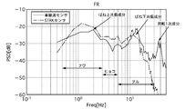
- FIG. 11 is a diagram in which the wheel speed frequency characteristic detected by the wheel speed sensor and the stroke frequency characteristic of a stroke sensor not mounted in the embodiment are simultaneously written.
- the frequency characteristic is a characteristic in which the vertical axis represents the magnitude of the amplitude with respect to the frequency as a scalar quantity. Comparing the frequency component of the wheel speed sensor 5 with the frequency component of the stroke sensor, it can be understood that substantially the same scalar amount is taken from the sprung resonance frequency component to the unsprung resonance frequency component. Therefore, the damping force is set based on this frequency characteristic among the detection values of the wheel speed sensor 5.
- the area where the sprung resonance frequency component exists is felt as if the occupant was thrown into the air by swinging the entire body of the occupant, in other words, the feeling that the gravitational acceleration acting on the occupant was reduced.
- the frequency region that brings about the waving region (0.5 to 3 Hz), and the region between the sprung resonance frequency component and the unsprung resonance frequency component is not a feeling that gravitational acceleration decreases.
- the feeling that the human body jumps in small increments when performing (trot), in other words, the frequency range that brings up and down movement that the whole body can follow is the leopard region (3 to 6 Hz), and the region where the unsprung resonance frequency component exists Is not a vertical movement until the mass of the human body follows, but a bull region (6 to 6) is used as a frequency region where vibration is transmitted to a part of the body such as the occupant's thigh. 23 Hz).
- FIG. 12 is a control block diagram illustrating frequency sensitive control in the sprung mass damping control according to the first embodiment.
- the band elimination filter 350 cuts noise other than the vibration component used for the main control from the wheel speed sensor value.
- the predetermined frequency domain dividing unit 351 divides the frequency band into a wide area, a horizontal area, and a bull area.
- the Hilbert transform processing unit 352 performs Hilbert transform on each divided frequency band, and converts it into a scalar quantity based on the amplitude of the frequency (specifically, an area calculated from the amplitude and the frequency band).
- the vehicle vibration system weight setting unit 353 sets weights at which vibrations in the frequency bands of the fur region, the leopard region, and the bull region are actually propagated to the vehicle.
- the human sense weight setting unit 354 sets weights at which vibrations in the frequency bands of the fur region, the leopard region, and the bull region are propagated to the occupant.
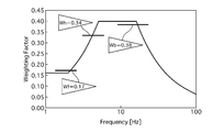
- FIG. 13 is a correlation diagram showing human sensory characteristics with respect to frequency.
- the occupant's sensitivity is relatively low with respect to the frequency, and the sensitivity gradually increases as the region moves to the high frequency region.
- the high frequency region above the bull region becomes difficult to be transmitted to the occupant.
- the human sense weight Wf of the wafe area is set to 0.17
- the human sense weight Wh of the leopard area is set to 0.34 which is larger than Wf
- the human sense weight Wb of the bull area is larger than Wf and Wh. Set to 0.38.
- the weight determining unit 355 calculates the ratio of the weight of each frequency band to the weight of each frequency band. If the weight of the wing area is a, the weight of the leopard area is b, and the weight of the bull area is c, the weight coefficient of the wing area is (a / (a + b + c)), and the weight coefficient of the leap area is (b / (a + b + c). )), And the weighting factor of the bull area is (c / (a + b + c)).
- the scalar amount calculation unit 356 multiplies the scalar amount of each frequency band calculated by the Hilbert transform processing unit 352 by the weight calculated by the weight determination unit 355, and outputs a final scalar amount. The processing so far is performed on the wheel speed sensor value of each wheel.
- the maximum value selection unit 357 selects the maximum value from the final scalar amounts calculated for each of the four wheels. Note that 0.01 in the lower part is set to avoid the denominator becoming 0 because the sum of the maximum values is used as the denominator in the subsequent processing.
- the ratio calculation unit 358 calculates the ratio using the sum of the scalar value maximum values in each frequency band as the denominator and the scalar value maximum value in the frequency band corresponding to the waving region as the numerator. In other words, the mixing ratio (hereinafter simply referred to as the ratio) of the wafer region included in all vibration components is calculated.
- the sprung resonance filter 359 performs filter processing of about 1.2 Hz of the sprung resonance frequency with respect to the calculated ratio, and extracts a sprung resonance frequency band component representing a waft region from the calculated ratio. In other words, since the wing area exists at about 1.2 Hz, the ratio of this area is considered to change at about 1.2 Hz. Then, the finally extracted ratio is output to the damping force control unit 35, and a frequency sensitive damping force control amount corresponding to the ratio is output.
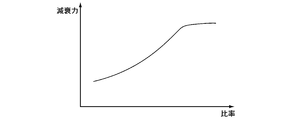
- FIG. 14 is a characteristic diagram showing the relationship between the vibration mixing ratio of the waft region and the damping force by the frequency sensitive control of the first embodiment.
- the vibration level of sprung resonance is reduced by setting the damping force high when the ratio of the wing area is large.
- the damping force is set high, the ratio of the leopard area and the bull area is small, so that high frequency vibration or vibration that moves with the leopard is not transmitted to the occupant.
- the damping force is set low, so that the vibration transmission characteristic more than the sprung resonance is reduced, the high frequency vibration is suppressed, and a smooth riding comfort is obtained.
- FIG. 15 is a diagram showing the wheel speed frequency characteristics detected by the wheel speed sensor 5 under a certain traveling condition. This is a characteristic that appears particularly when traveling on a road surface in which small unevenness such as a stone pavement continues.
- the damping force is determined by the value of the amplitude peak in Skyhook control. There is a problem that a very high damping force is set at an incorrect timing and high-frequency vibration is deteriorated.
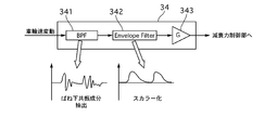
- FIG. 16 is a block diagram illustrating a control configuration of unsprung vibration suppression control according to the first embodiment.
- the unsprung resonance component extraction unit 341 extracts a unsprung resonance component by applying a band-pass filter to the wheel speed fluctuation output from the deviation calculation unit 321b in the traveling state estimation unit 32.
- the unsprung resonance component is extracted from the region of approximately 10 to 20 Hz of the wheel speed frequency component.
- the envelope waveform shaping unit 342 the extracted unsprung resonance component is scalarized, and the envelope waveform is shaped using the EnvelopeFilter.
- the gain multiplication unit 343 multiplies the scalarized unsprung resonance component by a gain, calculates an unsprung damping damping force control amount, and outputs the calculated amount to the damping force control unit 35.
- the unsprung resonance component is extracted by applying a bandpass filter to the wheel speed fluctuation output from the deviation calculating section 321b in the running state estimating section 32.
- the unsprung resonance component may be extracted by applying a bandpass filter to the driving force, or the unsprung resonance component may be extracted by the running state estimation unit 32 by estimating and calculating the unsprung speed along with the sprung speed. Good.
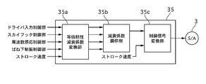
- FIG. 17 is a control block diagram illustrating a control configuration of the damping force control unit according to the first embodiment.
- the driver input damping force control amount output from the driver input control unit 31 the S / A attitude control amount output from the skyhook control unit 33a, and the frequency sensitive control unit 33b output
- the frequency sensitive damping force control amount, the unsprung damping damping force control amount output from the unsprung damping control unit 34, and the stroke speed calculated by the running state estimation unit 32 are input, and these values are equivalent. Convert to viscous damping coefficient.
- each damping coefficient is referred to as driver input damping coefficient k1, S / A attitude damping coefficient k2, frequency sensitive damping coefficient k3, unsprung). (Which is described as damping damping coefficient k4)), which arbitration is performed based on which damping coefficient is controlled, and a final damping coefficient is output.
- the control signal converter 35c converts the control signal (command current value) for S / A3 based on the attenuation coefficient and stroke speed adjusted by the attenuation coefficient adjuster 35b, and outputs the control signal to S / A3.
- the vehicle control apparatus has four control modes. First, the standard mode assuming a state where an appropriate turning state can be obtained while driving in a general urban area, and second, a state where a stable turning state can be obtained while actively driving a winding road etc. In sport mode, thirdly, comfort mode that assumes a state of driving with priority on ride comfort, such as when starting at a low vehicle speed, and fourthly, highway mode that assumes a state of traveling at high vehicle speed on highways with many straight lines is there.
- sport mode thirdly, comfort mode that assumes a state of driving with priority on ride comfort, such as when starting at a low vehicle speed
- highway mode that assumes a state of traveling at high vehicle speed on highways with many straight lines is there.
- priority is given to unsprung vibration suppression control by the unsprung vibration suppression control unit 34 while performing skyhook control by the skyhook control unit 33a.
- priority is given to driver input control by the driver input control unit 31, and skyhook control by the skyhook control unit 33a and unsprung vibration suppression control by the unsprung vibration suppression control unit 34 are performed.
- comfort mode the control for giving priority to the unsprung vibration damping control by the unsprung vibration damping control unit 34 is performed while performing the frequency sensitive control by the frequency sensitive control unit 33b.
- priority is given to driver input control by the driver input control unit 31, and control for adding the amount of unsprung vibration suppression control by the unsprung vibration control unit 34 to skyhook control by the skyhook control unit 33a is performed. To do.
- the adjustment of the attenuation coefficient in each mode will be described.
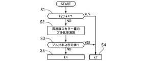
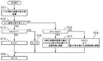
- FIG. 18 is a flowchart illustrating the attenuation coefficient arbitration process in the standard mode according to the first embodiment.
- step S1 it is determined whether or not the S / A attitude damping coefficient k2 is larger than the unsprung damping damping coefficient k4. If larger, the process proceeds to step S4 and k2 is set as the damping coefficient.
- step S2 a scalar amount ratio of the bull region is calculated based on the scalar amounts of the fur region, the leopard region, and the bull region described in the frequency response control unit 33b.
- step S3 it is determined whether or not the ratio of the bull area is equal to or greater than a predetermined value.
- the routine proceeds to step S5 and k4 is set.
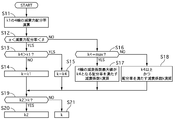
- FIG. 19 is a flowchart showing attenuation coefficient arbitration processing in the sport mode of the first embodiment.
- step S11 the four-wheel damping force distribution ratio is calculated based on the four-wheel driver input damping coefficient k1 set by the driver input control.
- the right front wheel driver input damping coefficient is k1fr
- the left front wheel driver input damping coefficient is k1fl
- the right rear wheel driver input damping coefficient is k1rr
- the left rear wheel driver input damping coefficient is k1rl
- xfl k1fl / (k1fr + k1fl + k1rr + k1rl)
- xrr k1rr / (k1fr + k1fl + k1rr + k1rl)
- xrl k1rl / (k1fr + k1fl + k1rr + k1rl)
- xrl k
- step S12 it is determined whether or not the damping force distribution ratio x is within a predetermined range (greater than ⁇ and smaller than ⁇ ). If it is within the predetermined range, it is determined that the distribution to each wheel is substantially equal, and the process proceeds to step S13. If any one is out of the predetermined range, the process proceeds to step S16. In step S13, it is determined whether or not the unsprung damping damping coefficient k4 is larger than the driver input damping coefficient k1. If it is determined that the unsprung damping damping coefficient k4 is larger, the process proceeds to step S15 and k4 is set as the first damping coefficient k. On the other hand, if it is determined that the unsprung damping damping coefficient k4 is equal to or less than the driver input damping coefficient k1, the process proceeds to step S14, and k1 is set as the first damping coefficient k.
- step S16 it is determined whether or not the unsprung damping damping coefficient k4 is the maximum value max that S / A3 can be set. If it is determined that the maximum value is max, the process proceeds to step S17, and otherwise, the process proceeds to step S18. move on.
- step S17 the maximum value of the four-wheel driver input damping coefficient k1 is the unsprung damping damping coefficient k4, and the damping coefficient that satisfies the damping force distribution ratio is calculated as the first damping coefficient k. In other words, a value that maximizes the damping coefficient while satisfying the damping force distribution rate is calculated.
- step S18 a damping coefficient that satisfies the damping force distribution ratio in a range where all the four-wheel driver input damping coefficients k1 are equal to or greater than k4 is calculated as the first damping coefficient k.
- a value that satisfies the damping force distribution ratio set by the driver input control and also satisfies the requirements of the unsprung vibration suppression control side is calculated.
- step S19 it is determined whether or not the first attenuation coefficient k set in each of the above steps is smaller than the S / A attitude attenuation coefficient k2 set by skyhook control. Since the damping coefficient requested on the side is larger, the process proceeds to step S20 and k2 is set. On the other hand, if it is determined that k is equal to or greater than k2, the process proceeds to step S21 and k is set.
- the damping force distribution rate required from the driver input control side is closely related to the vehicle body posture, and particularly because it is closely related to the driver's line-of-sight change due to the roll mode.
- the highest priority is to secure the damping force distribution ratio.
- the sky vehicle body posture can be maintained by selecting Skyhook control with select high.
- FIG. 20 is a flowchart illustrating the attenuation coefficient arbitration process in the comfort mode according to the first embodiment.
- step S30 it is determined whether or not the frequency sensitive damping coefficient k3 is larger than the unsprung damping damping coefficient k4. If it is determined that the frequency sensitive damping coefficient k3 is larger, the process proceeds to step S32 and the frequency sensitive damping coefficient k3 is set. On the other hand, if it is determined that the frequency sensitive damping coefficient k3 is equal to or less than the unsprung damping damping coefficient k4, the process proceeds to step S32 to set the unsprung damping damping coefficient k4.
- the comfort mode priority is given to unsprung resonance control that basically suppresses unsprung resonance.
- frequency sensitive control was performed as sprung mass damping control, and the optimum damping coefficient was set according to the road surface condition, so it was possible to achieve control that ensured riding comfort and lack of grounding feeling due to fluttering under the spring. Can be avoided by unsprung vibration suppression control.
- the attenuation coefficient may be switched according to the bull ratio of the frequency scalar quantity. As a result, the ride comfort can be further ensured in the super comfort mode.
- FIG. 21 is a flowchart illustrating the attenuation coefficient arbitration process in the highway mode according to the first embodiment. Since steps S11 to S18 are the same as the arbitration process in the sport mode, the description thereof is omitted.
- step S40 the S / A attitude attenuation coefficient k2 by the skyhook control is added to the first attenuation coefficient k that has been adjusted up to step S18, and is output.
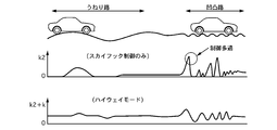
- FIG. 22 is a time chart showing a change in attenuation coefficient when traveling on a wavy road surface and an uneven road surface.
- the first damping coefficient k is always set as in the highway mode, a certain amount of damping force is always secured, and the vehicle body fluctuates even when the damping coefficient by the skyhook control is small. Such movement can be suppressed. Further, since it is not necessary to increase the skyhook control gain, it is possible to appropriately deal with road surface irregularities by using a normal control gain. In addition, since the skyhook control is performed with the first damping coefficient k set, unlike the damping coefficient limit, the damping coefficient decreasing process can be performed in the semi-active control region, and at the time of high-speed traveling It is possible to ensure a stable vehicle posture.
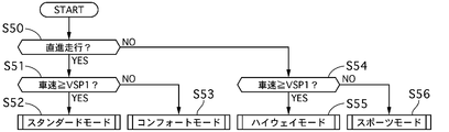
- FIG. 23 is a flowchart illustrating a mode selection process based on the running state in the attenuation coefficient arbitration unit of the first embodiment.
- step S50 it is determined whether or not the vehicle is in the straight traveling state based on the value of the steering angle sensor 7. If it is determined that the vehicle is traveling straight, the process proceeds to step S51. If it is determined that the vehicle is turning, the process proceeds to step S54. move on.
- step S51 it is determined based on the value of the vehicle speed sensor 8 whether or not the vehicle speed is equal to or higher than a predetermined vehicle speed VSP1 representing a high vehicle speed state.
- step S52 If it is determined that the vehicle speed is VSP1 or higher, the process proceeds to step S52 and the standard mode is selected. On the other hand, if it is determined that it is less than VSP1, the process proceeds to step S53 and the comfort mode is selected. In step S54, based on the value of the vehicle speed sensor 8, it is determined whether or not the vehicle speed is equal to or higher than a predetermined vehicle speed VSP1 representing a high vehicle speed state. If it is determined that the vehicle speed is VSP1 or higher, the process proceeds to step S55 and the highway mode is selected. On the other hand, if it is determined that it is less than VSP1, the process proceeds to step S56 to select the sport mode.
- the standard mode when driving at a high vehicle speed in a straight running state, the standard mode is selected to stabilize the vehicle body posture by skyhook control and to suppress the high frequency vibration such as leopard and bull. In addition, unsprung resonance can be suppressed. Further, when traveling at a low vehicle speed, by selecting the comfort mode, it is possible to suppress unsprung resonance while suppressing the input of vibrations such as leopard and bull to the occupant as much as possible.
- the highway mode is selected, so that it is controlled by the value obtained by adding the damping coefficient, so that basically a high damping force can be obtained.
- the sport mode is selected, so that the vehicle posture during turning is positively secured by driver input control, and unsprung resonance is suppressed while skyhook control is performed as appropriate. Can travel in a stable vehicle posture.
- the control example in which the driving state is detected and automatically switched is shown in the first embodiment.
- a changeover switch that can be operated by the driver is provided to select the driving mode. You may control to. As a result, ride comfort and turning performance according to the driving intention of the driver can be obtained.
- Example 1 has the following effects.
- S / A3 damping force variable shock absorber capable of changing damping force, driver input damping force control amount, S / A attitude control amount, and frequency-sensitive damping force that are damping forces that suppress vibration on the spring
- a driver input control unit 31b that calculates a control amount (a sprung mass damping control amount) and a sprung mass damping control unit 33 (a sprung mass damping control means), and an unsprung mass damping that suppresses unsprung vibration.
- a damping force control amount is calculated based on the larger control amount (FIG. 18: S1 ⁇ S4, FIG. 19: S11 ⁇ S12 ⁇ S13 ⁇ S14 ⁇ S19 ⁇ S20, FIG. 20: S30 ⁇ S32, FIG. 21: S11 ⁇ S12 ⁇ S13 ⁇ S15 etc.), damping force variable shock absorber Damping coefficient arbitration unit 35b for controlling the damping force, the control signal conversion unit 35c (the damping force control unit), with a. Therefore, it is possible to avoid a feeling of ground contact due to flapping of the unsprung while maintaining a stable vehicle posture by sprung mass damping control.
- the driver input control unit 31b is a control unit that calculates a driver input damping force control amount based on the damping force distribution ratio of each wheel corresponding to the target posture
- the damping coefficient arbitration unit 35b is a driver input damping force.
- the first damping coefficient k is a damping coefficient that satisfies the damping force distribution ratio in a range where all the four-wheel driver input damping coefficients k1 are k4 or more. Calculate. In other words, a value that satisfies the damping force distribution ratio set by the driver input control and also satisfies the requirements of the unsprung vibration suppression control side is calculated. Therefore, unsprung vibration suppression control can be achieved while maintaining a stable vehicle body posture.
- the damping coefficient arbitration unit 35b maintains the damping force distribution ratio based on the maximum value max.
- the attenuation coefficient k is calculated so as to perform (FIG. 19, 21: S11 ⁇ S12 ⁇ S16 ⁇ S17). Specifically, as shown in step S17 in the sport mode or highway mode, the maximum value of the four-wheel driver input damping coefficient k1 is the unsprung damping damping coefficient k4 and the damping coefficient satisfying the damping force distribution ratio is set. Calculated as the first attenuation coefficient k. In other words, a value that maximizes the damping coefficient while satisfying the damping force distribution rate is calculated.
- the damping force distribution rate required from the driver input control side is closely related to the vehicle body posture, and particularly to the driver's line-of-sight change due to the roll mode.
- securing the damping force distribution rate is a top priority, and the vehicle body posture is controlled in a state where the damping force distribution rate is maintained, so that a stable vehicle body posture can be maintained.
- the sprung mass damping control unit 33 calculates a sprung mass damping control amount based on a change in wheel speed. Thereby, it is not necessary to provide an expensive sensor such as a sprung vertical acceleration sensor or a stroke sensor. Generally, by estimating all the states from the wheel speed sensor 5 mounted on any vehicle, the number of parts can be reduced. Reduction and cost reduction can be achieved, and vehicle mountability can be improved.
- the unsprung vibration suppression control unit 34 calculates an unsprung vibration suppression control amount based on a change in wheel speed. Thereby, it is not necessary to provide an expensive sensor such as a sprung vertical acceleration sensor or a stroke sensor. Generally, by estimating all the states from the wheel speed sensor 5 mounted on any vehicle, the number of parts can be reduced. Reduction and cost reduction can be achieved, and vehicle mountability can be improved.
- a sprung mass damping control amount that is a damping force that suppresses vibration on the spring is calculated, a sprung mass damping control amount that is a damping force that suppresses vibration under the spring is calculated, and a sprung mass damping control is calculated.
- S / A controller 3a controller 3a (controller) that calculates the damping force control amount based on the larger one of the amount and the unsprung vibration suppression control amount, and S that generates the damping force according to the damping force control amount / A3. Therefore, it is possible to avoid a feeling of ground contact due to flapping of the unsprung while maintaining a stable vehicle posture by sprung mass damping control.
- the S / A controller 3a calculates a sprung mass damping control amount that is a damping force that suppresses vibration on the spring, and calculates a sprung mass damping control amount that is a damping force that suppresses vibration under the spring.
- the damping force control amount is calculated based on the larger one of the sprung mass damping control amount and the unsprung vibration damping control amount, and the damping force of S / A3 is calculated according to the damping force control amount. Control. Therefore, it is possible to avoid a feeling of ground contact due to flapping of the unsprung while maintaining a stable vehicle posture by sprung mass damping control.
Landscapes
- Engineering & Computer Science (AREA)
- Mechanical Engineering (AREA)
- Automation & Control Theory (AREA)
- Vehicle Body Suspensions (AREA)
- Control Of Driving Devices And Active Controlling Of Vehicle (AREA)
Abstract
Description
1a エンジンコントローラ(エンジン制御部)
2 ブレーキコントロールユニット
2a ブレーキコントローラ(ブレーキ制御部)
3 S/A(減衰力可変ショックアブソーバ)
3a S/Aコントローラ
5 車輪速センサ
6 一体型センサ
7 舵角センサ
8 車速センサ
20 ブレーキ
31 ドライバ入力制御部
32 走行状態推定部
33 ばね上制振制御部
33a スカイフック制御部
33b 周波数感応制御部
34 ばね下制振制御部
35 減衰力制御部
331 第1目標姿勢制御量演算部
332 エンジン姿勢制御量演算部
333 第2目標姿勢制御量演算部
334 ブレーキ姿勢制御量演算部
335 第3目標姿勢制御量演算部
336 ショックアブソーバ姿勢制御量演算部
図1は実施例1の車両の制御装置を表すシステム概略図である。車両には、動力源であるエンジン1と、各輪に摩擦力による制動トルクを発生させるブレーキ20(以下、個別の輪に対応するブレーキを表示するときには右前輪ブレーキ:20FR、左前輪ブレーキ:20FL、右後輪ブレーキ:20RR、左後輪ブレーキ:20RLと記載する。)と、各輪と車体との間に設けられ減衰力を可変に制御可能なショックアブソーバ3(以下、S/Aと記載する。個別の輪に対応するS/Aを表示するときには右前輪S/A:3FR、左前輪S/A:3FL、右後輪S/A:3RR、左後輪S/A:3RLと記載する。)と、を有する。
実施例1の車両の制御装置にあっては、ばね上に生じる振動状態を制御するために、3つのアクチュエータを使用する。このとき、それぞれの制御がばね上状態を制御するため、相互干渉が問題となる。また、エンジン1によって制御可能な要素と、ブレーキ20によって制御可能な要素と、S/A3によって制御可能な要素はそれぞれ異なり、これらをどのように組み合わせて制御するべきかが問題となる。
例えば、ブレーキ20はバウンス運動とピッチ運動の制御が可能であるが、両方を行なうと減速感が強く運転者に違和感を与えやすい。また、S/A3はロール運動とバウンス運動とピッチ運動の全てを制御可能であるが、S/A3によって全ての制御を行う場合、S/A3の製造コストの上昇を招き、また、減衰力が高くなる傾向があることから路面側からの高周波振動が入力されやすく、やはり運転者に違和感を与えやすい。言い換えると、ブレーキ20による制御は高周波振動の悪化を招くことは無いが減速感の増大を招き、S/A3による制御は減速感を招くことは無いが高周波振動の入力を招くというトレードオフが存在する。
(1)エンジン1及びブレーキ20による制御を優先的に行うことで、S/A3による制御量を抑制する。
(2)ブレーキ20の制御対象運動をピッチ運動に限定することで、ブレーキ20による制御での減速感を解消する。
(3)エンジン1及びブレーキ20による制御量を実際に出力可能な制御量よりも制限して出力することで、S/A3での負担を低減しつつ、エンジン1やブレーキ20の制御に伴って生じる違和感を抑制する。
(4)全てのアクチュエータによりスカイフック制御を行う。このとき、一般にスカイフック制御に必要とされるストロークセンサやばね上上下加速度センサ等を使用することなく、全ての車両に搭載されている車輪速センサを利用して安価な構成でスカイフック制御を実現する。
(5)S/A3によるばね上制御を行なう際、スカイフック制御のようなベクトル制御では対応が困難な高周波振動の入力に対し、新たにスカラー制御(周波数感応制御)を導入する。
(6)走行状態に応じて、S/A3が実現する制御状態を適宜選択することで、走行状況に応じた適切な制御状態を提供する。
以上が、実施例において構成した全体の制御システムの概要である。以下、これらを実現する個別の内容について、順次説明する。
まず、ドライバ入力制御部について説明する。ドライバ入力制御部31は、エンジン1のトルク制御によって運転者の要求する車両姿勢を達成するエンジン側ドライバ入力制御部31aと、S/A3の減衰力制御によって運転者の要求する車両姿勢を達成するS/A側ドライバ入力制御部31bと、を有する。エンジン側ドライバ入力制御部31a内では、前輪と後輪の接地荷重変動を抑制する接地荷重変動抑制制御量、舵角センサ7や車速センサ8からの信号に基づいて運転者の達成したい車両挙動に対応するヨー応答制御量を演算し、エンジン制御部1aに対して出力する。
S/A側ドライバ入力制御部31bでは、舵角センサ7や車速センサ8からの信号に基づいて運転者の達成したい車両挙動に対応するドライバ入力減衰力制御量を演算し、減衰力制御部35に対して出力する。例えば、運転者が旋回中において、車両のノーズ側が浮き上がると、運転者の視界が路面から外れやすくなることから、この場合にはノーズ浮き上がりを防止するように4輪の減衰力をドライバ入力減衰力制御量として出力する。また、旋回時に発生するロールを抑制するドライバ入力減衰力制御量を出力する。
ここで、S/A側ドライバ入力制御によって行われるロール抑制制御について説明する。図3は実施例1のロールレイト抑制制御の構成を表す制御ブロック図である。横加速度推定部31b1では、舵角センサ7により検出された前輪舵角δfと、後輪舵角δr(後輪操舵装置を備えた場合は実後輪舵角を、それ以外の場合は適宜0でよい。)と、車速センサ8により検出された車速VSPに基づいて横加速度Ygを推定する。この横加速度Ygは、ヨーレイト推定値γを用いて以下の式により算出される。
Yg=VSP・γ
なおヨーレイト推定値γは以下の式により算出される。
ゲイン乗算部31b5では、横加速度Yg、横加速度微分値dYg、横加速度DCカット成分F(dYg)、90°位相遅れ成分F(Yg)にそれぞれゲインを乗算する。各ゲインは、操舵角に対するロールレイト伝達関数に基づいて設定する。また各ゲインは、後述する4つの制御モードに応じて調整しても良い。二乗演算部31b6では、ゲインを乗算した各成分の二乗して出力する。合成部31b7では、二乗演算部31b6が出力した値を足し合わせる。ゲイン乗算部31b8では、足し合わせた各成分の二乗の値にゲインを乗算して出力する。平方根演算部31b9は、ゲイン乗算部31b7が出力した値の平方根を演算することで、ロールレイト抑制制御用のドライバ入力姿勢制御量を演算し、減衰力制御部35に対して出力する。
90°位相進み成分作成部31b2、90°位相遅れ成分作成部31b3、90°位相遅れ成分作成部31b4、ゲイン乗算部31b5、二乗演算部31b6、合成部31b7、ゲイン乗算部31b8、平方根演算部31b9は、ヒルベルト変換を利用した包絡波形を生成するヒルベルト変換部31b10に相当する。
時刻t1において、運転者が操舵を開始すると、ロールレイトが徐々に発生し始める。このとき、90°位相進み成分dYgを加算して包絡波形を形成し、包絡波形に基づくスカラー量に基づいてドライバ入力姿勢制御量を演算することで、操舵初期におけるロールレイトの発生を抑制することができる。さらに、横加速度DCカット成分F(dYg)を加算して包絡波形を形成することで、運転者が操舵を開始もしくは終了する際の過渡的な状態において発生するロールレイトを効率的に抑制することができる。言い換えると、ロールの発生が安定している定常旋回状態では、過度に減衰力を高めることがなく、乗り心地の悪化を回避できる。
次に、時刻t2において、運転者が保舵状態となると、90°位相進み成分dYgおよび横加速度DCカット成分F(dYg)は無くなり、今度は90°位相遅れ成分F(Yg)が加算される。このとき、定常旋回状態でロールレイト自体の変化はさほどない場合であっても、一旦ロールした後に、ロールの揺り返しに相当するロールレイト共振成分が発生する。仮に、位相遅れ成分F(Yg)が加算されていないと、時刻t2から時刻t3における減衰力は小さな値に設定されてしまい、ロールレイト共振成分による車両挙動の不安定化を招くおそれがある。このロールレイト共振成分を抑制するために90°位相遅れ成分F(Yg)を付与するものである。
次に、走行状態推定部について説明する。図5は実施例1の走行状態推定部の構成を表す制御ブロック図である。実施例1の走行状態推定部32では、基本的に車輪速センサ5により検出された車輪速に基づいて、後述するばね上制振制御部33のスカイフック制御に使用する各輪のストローク速度、バウンスレイト、ロールレイト及びピッチレイトを算出する。まず、各輪の車輪速センサ5の値がストローク速度演算部321に入力され、ストローク速度演算部321において演算された各輪のストローク速度からばね上速度を演算する。
ここで、基準車輪速演算部300について説明する。図7は実施例1の基準車輪速演算部の構成を表すブロック図である。基準車輪速とは、各車輪速のうち、種々の外乱が除去された値を指すものである。言い換えると、車輪速センサ値と基準車輪速との差分は、車体のバウンス挙動、ロール挙動、ピッチ挙動又はばね下上下振動によって発生したストロークに応じて変動した成分と関連がある値であり、実施例では、この差分に基づいてストローク速度を推定する。
VFL=(V-Tf/2・γ)cosδf+(Vx+Lf・γ)sinδf
VFR=(V+Tf/2・γ)cosδf+(Vx+Lf・γ)sinδf
VRL=(V-Tr/2・γ)cosδr+(Vx-Lr・γ)sinδr
VRR=(V+Tr/2・γ)cosδr+(Vx-Lr・γ)sinδr
尚、車両に横滑りが発生してない通常走行時を仮定すると、車体横速度Vxは0を入力すればよい。これをそれぞれの式においてVを基準とする値に書き換えると以下のように表される。この書き換えにあたり、Vをそれぞれの車輪に対応する値としてV0FL、V0FR、V0RL、V0RR(第1車輪速に相当)と記載する。
(式2)
V0FL={VFL-Lf・γsinδf}/cosδf+Tf/2・γ
V0FR={VFR-Lf・γsinδf}/cosδf-Tf/2・γ
V0RL={VRL+Lr・γsinδr}/cosδr+Tr/2・γ
V0RR={VRR+Lf・γsinδf}/cosδr-Tr/2・γ
V0F=(V0FL+V0FR)/2
V0R=(V0RL+V0RR)/2
これにより、ロールに基づく外乱を除去した第2車輪速V0F、V0Rが得られる。
(式3)
VbFL=VbFR=VbRL=VbRR={Lr/(Lf+Lr)}V0F+{Lf/(Lf+Lr)}V0R
基準車輪速再配分部304では、(式1)に示す車体プランビューモデルのVにVbFL(=VbFR=VbRL=VbRR)をそれぞれ代入し、最終的な各輪の基準車輪速VFL、VFR、VRL、VRRを算出し、それぞれタイヤ半径r0で除算して基準車輪速ω0を算出する。
スカイフック制御とは、S/A3のストローク速度とばね上速度の関係に基づいて減衰力を設定し、ばね上を姿勢制御することでフラットな走行状態を達成するものである。ここで、スカイフック制御によってばね上の姿勢制御を達成するには、ばね上速度をフィードバックする必要がある。今、車輪速センサ5から検出可能な値はストローク速度であり、ばね上に上下加速度センサ等を備えていないことから、ばね上速度は推定モデルを用いて推定する必要がある。以下、推定モデルの課題及び採用すべきモデル構成について説明する。
(推定式1)
Ms・ddz2=-Ks(z2-z1)-Cs(dz2-dz1)
この関係式をラプラス変換して整理すると下記のように表される。
(推定式2)
dz2=-(1/Ms)・(1/s2)・(Cs・s+Ks)(dz2-dz1)
ここで、dz2-dz1はストローク速度(Vz_sFL、Vz_sFR、Vz_sRL、Vz_sRR)であることから、ばね上速度はストローク速度から算出できる。しかし、スカイフック制御によって減衰力が変更されると、推定精度が著しく低下するため、コンベ車両モデルでは大きな姿勢制御力(減衰力変更)を与えられないという問題が生じる。
(推定式3)
dz2=-(1/Ms)・(1/s2)・{(Cs+Cv)・s+Ks}(dz2-dz1)
ただし、
dz2・(dz2-dz1)≧0のとき Cv=Csky・{dz2/(dz2-dz1)}
dz2・(dz2-dz1)<0のとき Cv=0
すなわち、Cvは不連続な値となる。
dz2=-(1/s)・{1/(s+Csky/Ms)}・{(Cs/Ms)s+(Ks/Ms)}(dz2-dz1)
この場合、擬似微分項{(Cs/Ms)s+(Ks/Ms)}には不連続性が生じず、{1/(s+Csky/Ms)}の項はローパスフィルタで構成できる。よって、フィルタ応答が安定し、適切な推定精度を得ることができる。尚、ここで、アクティブスカイフックモデルを採用しても、実際にはセミアクティブ制御しかできないことから、制御可能領域が半分となる。よって、推定されるばね上速度の大きさはばね上共振以下の周波数帯で実際よりも小さくなるが、スカイフック制御において最も重要なのは位相であり、位相と符号との対応関係が維持できればスカイフック制御は達成され、ばね上速度の大きさは他の係数等によって調整可能であることから問題はない。
以上の関係式から、xsB、xsR、xsP、xsWの微分dxsB等は以下の式で表される。
dxsB=1/4(Vz_sFL+Vz_sFR+Vz_sRL+Vz_sRR)
dxsR=1/4(Vz_sFL-Vz_sFR+Vz_sRL-Vz_sRR)
dxsP=1/4(-Vz_sFL-Vz_sFR+Vz_sRL+Vz_sRR)
dxsW=1/4(-Vz_sFL+Vz_sFR+Vz_sRL-Vz_sRR)
dB=GB・dxsB
dR=GR・dxsR
dP=GP・dxsP
以上から、各輪のストローク速度に基づいて、実際の車両におけるばね上の状態推定が達成できる。
次に、ばね上制振制御部33の構成について説明する。図2に示すように、ばね上制振制御部33は、上述のばね上速度推定値に基づいて姿勢制御を行うスカイフック制御部33aと、路面入力周波数に基づきばね上振動を抑制する周波数感応制御部33bとを有する。
実施例1の車両の制御装置にあっては、ばね上姿勢制御を達成するアクチュエータとして、エンジン1と、ブレーキ20と、S/A3の三つを備えている。このうち、スカイフック制御部33aでは、S/A3についてはバウンスレイト、ロールレイト、ピッチレイトの3つを制御対象とし、エンジン1についてはバウンスレイト及びピッチレイトを制御対象とし、ブレーキ20についてはピッチレイトを制御対象とする。ここで、作用の異なる複数のアクチュエータに対して制御量を割り付けてばね上状態を制御するには、それぞれに共通の制御量を用いる必要がある。実施例1では、上述の走行状態推定部32により推定されたばね上速度を用いることで、各アクチュエータに対する制御量を決定することができる。
FB=CskyB・dB
ロール方向のスカイフック制御量は、
FR=CskyR・dR
ピッチ方向のスカイフック制御量は、
FP=CskyP・dP
となる。FBはエンジン1及びS/A3にバウンス姿勢制御量として送信され、FRはS/A3においてのみ実施される制御であることから、ロール姿勢制御量として減衰力制御部35に送信される。
図9は実施例1のピッチ制御を行う際の各アクチュエータ制御量算出処理を表す制御ブロック図である。スカイフック制御部33aは、全てのアクチュエータに共通して使用可能な制御量である第1目標姿勢制御量である目標ピッチレイトを演算する第1目標姿勢制御量演算部331と、エンジン1によって達成するエンジン姿勢制御量を演算するエンジン姿勢制御量演算部332と、ブレーキ20によって達成するブレーキ姿勢制御量を演算するブレーキ姿勢制御量演算部334と、S/A3によって達成するS/A姿勢制御量を演算するS/A姿勢制御量演算部336とを有する。
ここで、ブレーキピッチ制御について説明する。一般に、ブレーキ20については、バウンスとピッチの両方を制御可能であることから、両方を行うことが好ましいとも言える。しかし、ブレーキ20によるバウンス制御は4輪同時に制動力を発生させるため、制御優先度が低い方向にも関わらず、制御効果が得にくい割には減速感が強く、運転者にとって違和感となる傾向があった。そこで、ブレーキ20についてはピッチ制御に特化した構成とした。図10は実施例1のブレーキピッチ制御を表す制御ブロック図である。車体の質量をm、前輪の制動力をBFf、後輪の制動力をBFr、車両重心点と路面との間の高さをHcg、車両の加速度をa、ピッチモーメントをMp、ピッチレイトをVpとすると、以下の関係式が成立する。
m・a・Hcg=Mp
Mp=(BFf+BFr)・Hcg
ここで、ピッチレイトVpが正、つまり前輪側が沈み込んでいるときには制動力を与えてしまうと、より前輪側が沈み込み、ピッチ運動を助長してしまうため、この場合は制動力を付与しない。一方、ピッチレイトVpが負、つまり前輪側が浮き上がっているときには制動ピッチモーメントが制動力を与えて前輪側の浮き上がりを抑制する。これにより、運転者の視界を確保し、前方を見やすくすることで、安心感、フラット感の向上に寄与する。以上から、
Vp>0(前輪沈み込み)のとき Mp=0
Vp≦0(前輪浮き上がり)のとき Mp=CskyP・Vp
の制御量を与えるものである。これにより、車体のフロント側の浮き上がり時のみ制動トルクを発生させるため、浮き上がりと沈み込み両方に制動トルクを発生する場合に比べて、発生する減速度を小さくすることができる。また、アクチュエータ作動頻度も半分で済むため、低コストなアクチュエータを採用できる。
次に、減速感低減処理について説明する。この処理は、ブレーキ姿勢制御量演算部334内で行なわれる上記制限値による制限に対応する処理である。2乗処理部3342aでは、ピッチレイト信号を2乗処理する。これにより符号を反転させると共に、制御力の立ち上がりを滑らかにする。ピッチレイト2乗減衰モーメント演算部3342bでは、2乗処理されたピッチレイトに2乗処理を考慮したピッチ項のスカイフックゲインCskyPを乗算してピッチモーメントMpを演算する。目標減速度算出部3342cでは、ピッチモーメントMpを質量m及び車両重心点と路面との間の高さHcgにより除算して目標減速度を演算する。
次に、ばね上制振制御部内における周波数感応制御処理について説明する。実施例1では、基本的に車輪速センサ5の検出値に基づいてばね上速度を推定し、それに基づくスカイフック制御を行うことでばね上制振制御を達成する。しかしながら、車輪速センサ5では十分に推定精度が担保出来ないと考えられる場合や、走行状況や運転者の意図によっては積極的に快適な走行状態(車体フラット感よりも柔らかな乗り心地)を担保したい場合もある。このような場合には、スカイフック制御のようにストローク速度とばね上速度の符号の関係(位相等)が重要となるベクトル制御では僅かな位相ずれによって適正な制御が困難となる場合があることから、振動特性のスカラー量に応じたばね上制振制御である周波数感応制御を導入することとした。
車両振動系重み設定部353では、フワ領域、ヒョコ領域及びブル領域の各周波数帯の振動が実際に車両に伝播される重みを設定する。人間感覚重み設定部354では、フワ領域、ヒョコ領域及びブル領域の各周波数帯の振動が乗員に伝播される重みを設定する。
スカラー量演算部356では、ヒルベルト変換処理部352により算出された各周波数帯のスカラー量に重み決定手段355において算出された重みを乗算し、最終的なスカラー量を出力する。ここまでの処理は、各輪の車輪速センサ値に対して行なわれる。
これに対し、周波数感応制御のようにベクトルではなくスカラー量に基づいて制御する場合、図15に示すような路面にあってはフワ領域の比率が小さいことから低い減衰力が設定されることになる。これにより、ブル領域の振動の振幅が大きい場合であっても十分に振動伝達特性が減少するため、高周波振動の悪化を回避することができるものである。以上から、例え高価なセンサ等を備えてスカイフック制御を行ったとしても位相推定精度が悪化することで制御が困難な領域では、スカラー量に基づく周波数感応制御によって高周波振動を抑制できるものである。
次に、ばね下制振制御部の構成について説明する。図8(a)のコンベ車両において説明したように、タイヤも弾性係数と減衰係数を有することから共振周波数帯が存在する。ただし、タイヤの質量はばね上の質量に比べて小さく、弾性係数も高いため、ばね上共振よりも高周波数側に存在する。このばね下共振成分により、ばね下においてタイヤがバタバタ動いてしまい、接地性が悪化するおそれがある。また、ばね下でのバタつきは乗員に不快感を与えるおそれもある。そこで、ばね下共振によるバタつきを抑制するために、ばね下共振成分に応じた減衰力を設定するものである。
次に、減衰力制御部35の構成について説明する。図17は実施例1の減衰力制御部の制御構成を表す制御ブロック図である。等価粘性減衰係数変換部35aでは、ドライバ入力制御部31から出力されたドライバ入力減衰力制御量と、スカイフック制御部33aから出力されたS/A姿勢制御量と、周波数感応制御部33bから出力された周波数感応減衰力制御量と、ばね下制振制御部34から出力されたばね下制振減衰力制御量と、走行状態推定部32により演算されたストローク速度が入力され、これらの値を等価粘性減衰係数に変換する。
次に、減衰係数調停部35bの調停内容について説明する。実施例1の車両の制御装置にあっては、4つの制御モードを有する。第1に一般的な市街地などを走行しつつ適度な旋回状態が得られる状態を想定したスタンダードモード、第2にワインディングロードなどを積極的に走行しつつ安定した旋回状態が得られる状態を想定したスポーツモード、第3に低車速発進時など、乗り心地を優先して走行する状態を想定したコンフォートモード、第4に直線状態の多い高速道路等を高車速で走行する状態を想定したハイウェイモードである。
スポーツモードでは、ドライバ入力制御部31によるドライバ入力制御を優先しつつ、スカイフック制御部33aによるスカイフック制御とばね下制振制御部34によるばね下制振制御とを実施する。
コンフォートモードでは、周波数感応制御部33bによる周波数感応制御を行いつつ、ばね下制振制御部34によるばね下制振制御を優先する制御を実施する。
ハイウェイモードでは、ドライバ入力制御部31によるドライバ入力制御を優先しつつ、スカイフック制御部33aによるスカイフック制御にばね下制振制御部34によるばね下制振制御の制御量を加算する制御を実施する。
以下、これら各モードにおける減衰係数の調停について説明する。
図18は実施例1のスタンダードモードにおける減衰係数調停処理を表すフローチャートである。
ステップS1では、S/A姿勢減衰係数k2がばね下制振減衰係数k4より大きいか否かを判断し、大きいときはステップS4に進んで減衰係数としてk2を設定する。
ステップS2では、周波数感応制御部33bにおいて説明したフワ領域、ヒョコ領域及びブル領域のスカラー量に基づいて、ブル領域のスカラー量比率を演算する。
ステップS3では、ブル領域の比率が所定値以上か否かを判断し、所定値以上の場合は高周波振動による乗り心地悪化が懸念されることからステップS4に進み、減衰係数として低い値であるk2を設定する。一方、ブル領域の比率が上記所定値未満の場合は減衰係数を高く設定しても高周波振動による乗り心地悪化の心配が少ないことからステップS5に進んでk4を設定する。
図19は実施例1のスポーツモードにおける減衰係数調停処理を表すフローチャートである。
ステップS11では、ドライバ入力制御により設定された4輪のドライバ入力減衰係数k1に基づいて4輪減衰力配分率を演算する。右前輪のドライバ入力減衰係数をk1fr、左前輪のドライバ入力減衰係数をk1fl、右後輪のドライバ入力減衰係数をk1rr、左後輪のドライバ入力減衰係数をk1rl、各輪の減衰力配分率をxfr、xfl、xrr、xrlとすると、
xfr=k1fr/(k1fr+k1fl+k1rr+k1rl)
xfl=k1fl/(k1fr+k1fl+k1rr+k1rl)
xrr=k1rr/(k1fr+k1fl+k1rr+k1rl)
xrl=k1rl/(k1fr+k1fl+k1rr+k1rl)
により算出される。
ステップS13では、ばね下制振減衰係数k4がドライバ入力減衰係数k1より大きいか否かを判断し、大きいと判断した場合はステップS15に進み、第1減衰係数kとしてk4を設定する。一方、ばね下制振減衰係数k4がドライバ入力減衰係数k1以下であると判断した場合はステップS14に進み、第1減衰係数kとしてk1を設定する。
ステップS17では、4輪のドライバ入力減衰係数k1の最大値がばね下制振減衰係数k4となり、かつ、減衰力配分率を満たす減衰係数を第1減衰係数kとして演算する。言い換えると、減衰力配分率を満たしつつ減衰係数が最も高くなる値を演算する。
ステップS18では、4輪のドライバ入力減衰係数k1がいずれもk4以上となる範囲で減衰力配分率を満たす減衰係数を第1減衰係数kとして演算する。言い換えると、ドライバ入力制御によって設定される減衰力配分率を満たし、かつ、ばね下制振制御側の要求をも満たす値を演算する。
図20は実施例1のコンフォートモードにおける減衰係数調停処理を表すフローチャートである。
ステップS30では、周波数感応減衰係数k3がばね下制振減衰係数k4より大きいか否かを判断し、大きいと判断した場合はステップS32に進んで周波数感応減衰係数k3を設定する。一方、周波数感応減衰係数k3がばね下制振減衰係数k4以下であると判断した場合はステップS32に進んでばね下制振減衰係数k4を設定する。
図21は実施例1のハイウェイモードにおける減衰係数調停処理を表すフローチャートである。尚、ステップS11からS18までは、スポーツモードにおける調停処理と同じであるため、説明を省略する。
ステップS40では、ステップS18までで調停された第1減衰係数kにスカイフック制御によるS/A姿勢減衰係数k2を加算して出力する。
次に、上記各走行モードを選択するモード選択処理について説明する。図23は実施例1の減衰係数調停部において走行状態に基づくモード選択処理を表すフローチャートである。
ステップS50では、舵角センサ7の値に基づいて直進走行状態か否かを判断し、直進走行状態と判断された場合にはステップS51に進み、旋回状態と判断された場合にはステップS54に進む。
ステップS51では、車速センサ8の値に基づいて高車速状態を表す所定車速VSP1以上か否かを判断し、VSP1以上と判断された場合にはステップS52に進んでスタンダードモードを選択する。一方、VSP1未満と判断された場合にはステップS53に進んでコンフォートモードを選択する。
ステップS54では、車速センサ8の値に基づいて高車速状態を表す所定車速VSP1以上か否かを判断し、VSP1以上と判断された場合にはステップS55に進んでハイウェイモードを選択する。一方、VSP1未満と判断された場合にはステップS56に進んでスポーツモードを選択する。
(1)減衰力を変更可能なS/A3(減衰力可変ショックアブソーバ)と、ばね上の振動を抑制する減衰力であるドライバ入力減衰力制御量、S/A姿勢制御量、周波数感応減衰力制御量(ばね上制振制御量)を演算するドライバ入力制御部31b及びばね上制振制御部33(ばね上制振制御手段)と、ばね下の振動を抑制する減衰力であるばね下制振減衰力制御量(ばね下制振制御量)を演算するばね下制振制御部34(ばね下制振制御手段)と、ばね上制振制御量とばね下制振制御量とのうち、大きい方の制御量に基づいて減衰力制御量を演算し(図18:S1→S4、図19:S11→S12→S13→S14→S19→S20、図20:S30→S32、図21:S11→S12→S13→S15等)、減衰力可変ショックアブソーバの減衰力を制御する減衰係数調停部35b,制御信号変換部35c(減衰力制御手段)と、を備えた。
よって、ばね上制振制御により安定した車両姿勢を維持しつつ、ばね下がばたつくことによる接地感不足を回避することができる。
具体的には、スポーツモードやハイウェイモードにおけるステップS18に示すように、4輪のドライバ入力減衰係数k1がいずれもk4以上となる範囲で減衰力配分率を満たす減衰係数を第1減衰係数kとして演算する。言い換えると、ドライバ入力制御によって設定される減衰力配分率を満たし、かつ、ばね下制振制御側の要求をも満たす値を演算する。
よって、安定した車体姿勢を維持しつつばね下の制振制御も達成することができる。
具体的には、スポーツモードやハイウェイモードにおけるステップS17に示すように、4輪のドライバ入力減衰係数k1の最大値がばね下制振減衰係数k4となり、かつ、減衰力配分率を満たす減衰係数を第1減衰係数kとして演算する。言い換えると、減衰力配分率を満たしつつ減衰係数が最も高くなる値を演算する。
ドライバ入力制御側から要求される減衰力配分率は、車体姿勢と密接に関連し、特にロールモードによるドライバの視線変化との関連も深いことから、ドライバ入力制御側から要求された減衰係数そのものではなく、減衰力配分率の確保を最優先事項とし、減衰力配分率が保たれた状態で車体姿勢を制御することで、安定した車体姿勢を維持することができる。
これにより、ばね上上下加速度センサや、ストロークセンサといった高価なセンサを備える必要がなく、一般的にどの車両にも搭載されている車輪速センサ5から全ての状態を推定することで、部品点数の削減及びコストの削減を図ることができ、車両搭載性を向上できる。
これにより、ばね上上下加速度センサや、ストロークセンサといった高価なセンサを備える必要がなく、一般的にどの車両にも搭載されている車輪速センサ5から全ての状態を推定することで、部品点数の削減及びコストの削減を図ることができ、車両搭載性を向上できる。
よって、ばね上制振制御により安定した車両姿勢を維持しつつ、ばね下がばたつくことによる接地感不足を回避することができる。
よって、ばね上制振制御により安定した車両姿勢を維持しつつ、ばね下がばたつくことによる接地感不足を回避することができる。
Claims (7)
- 減衰力を変更可能な減衰力可変ショックアブソーバと、
ばね上の振動を抑制する減衰力であるばね上制振制御量を演算するばね上制振制御手段と、
ばね下の振動を抑制する減衰力であるばね下制振制御量を演算するばね下制振制御手段と、
前記ばね上制振制御量と前記ばね下制振制御量とのうち、大きい方の制御量に基づいて減衰力制御量を演算し、前記減衰力可変ショックアブソーバの減衰力を制御する減衰力制御手段と、
を備えたことを特徴とする車両の制御装置。 - 請求項1に記載の車両の制御装置において、
前記ばね上制振制御手段は、目標姿勢に対応する各輪の減衰力配分率に基づいて前記ばね上制振制御量を演算する手段であり、
前記減衰力制御手段は、前記ばね上制振制御量が前記ばね下制振制御量以下のときは、前記ばね下制振制御量に基づいて前記減衰力配分率を維持するよう前記減衰力制御量を演算することを特徴とする車両の制御装置。 - 請求項2に記載の車両の制御装置において、
前記減衰力制御手段は、前記減衰力制御量が予め設定された所定値以上のときは、前記所定値に基づいて前記減衰力配分率を維持するよう前記減衰力制御量を演算することを特徴とする車両の制御装置。 - 請求項1ないし3いずれか一つに記載の車両の制御装置において、
前記ばね上制振制御手段は、車輪速の変化に基づいてばね上制振制御量を演算することを特徴とする車両の制御装置。 - 請求項1ないし4いずれか一つに記載の車両の制御装置において、
前記ばね下制振制御手段は、車輪速の変化に基づいてばね下制振制御量を演算することを特徴とする車両の制御装置。 - ばね上の振動を抑制する減衰力であるばね上制振制御量を演算し、ばね下の振動を抑制する減衰力であるばね下制振制御量を演算し、前記ばね上制振制御量と前記ばね下制振制御量とのうち、大きい方の制御量に基づいて減衰力制御量を演算するコントローラと、
前記減衰力制御量に応じた減衰力を発生する減衰力可変ショックアブソーバと、
を備える車両の制御装置。 - コントローラが、
ばね上の振動を抑制する減衰力であるばね上制振制御量を演算し、
ばね下の振動を抑制する減衰力であるばね下制振制御量を演算し、
前記ばね上制振制御量と前記ばね下制振制御量とのうち、大きい方の制御量に基づいて減衰力制御量を演算し、前記減衰力制御量に応じて減衰力可変ショックアブソーバの減衰力を制御することを特徴とする車両の制御方法。
Priority Applications (4)
| Application Number | Priority Date | Filing Date | Title |
|---|---|---|---|
| JP2013555266A JP5733431B2 (ja) | 2012-01-25 | 2013-01-22 | 車両の制御装置及び車両の制御方法 |
| EP13741127.8A EP2808191B1 (en) | 2012-01-25 | 2013-01-22 | Vehicle control system and vehicle control method |
| CN201380006748.6A CN104080629B (zh) | 2012-01-25 | 2013-01-22 | 车辆的控制装置和车辆的控制方法 |
| US14/368,602 US9415659B2 (en) | 2012-01-25 | 2013-01-22 | Vehicle control device and vehicle control method |
Applications Claiming Priority (2)
| Application Number | Priority Date | Filing Date | Title |
|---|---|---|---|
| JP2012-012590 | 2012-01-25 | ||
| JP2012012590 | 2012-01-25 |
Publications (1)
| Publication Number | Publication Date |
|---|---|
| WO2013111739A1 true WO2013111739A1 (ja) | 2013-08-01 |
Family
ID=48873459
Family Applications (1)
| Application Number | Title | Priority Date | Filing Date |
|---|---|---|---|
| PCT/JP2013/051179 WO2013111739A1 (ja) | 2012-01-25 | 2013-01-22 | 車両の制御装置及び車両の制御方法 |
Country Status (5)
| Country | Link |
|---|---|
| US (1) | US9415659B2 (ja) |
| EP (1) | EP2808191B1 (ja) |
| JP (1) | JP5733431B2 (ja) |
| CN (1) | CN104080629B (ja) |
| WO (1) | WO2013111739A1 (ja) |
Families Citing this family (30)
| Publication number | Priority date | Publication date | Assignee | Title |
|---|---|---|---|---|
| US9452654B2 (en) | 2009-01-07 | 2016-09-27 | Fox Factory, Inc. | Method and apparatus for an adjustable damper |
| US20120305350A1 (en) | 2011-05-31 | 2012-12-06 | Ericksen Everet O | Methods and apparatus for position sensitive suspension damping |
| US10060499B2 (en) | 2009-01-07 | 2018-08-28 | Fox Factory, Inc. | Method and apparatus for an adjustable damper |
| US11306798B2 (en) | 2008-05-09 | 2022-04-19 | Fox Factory, Inc. | Position sensitive suspension damping with an active valve |
| US20100170760A1 (en) | 2009-01-07 | 2010-07-08 | John Marking | Remotely Operated Bypass for a Suspension Damper |
| US10047817B2 (en) * | 2009-01-07 | 2018-08-14 | Fox Factory, Inc. | Method and apparatus for an adjustable damper |
| US8627932B2 (en) | 2009-01-07 | 2014-01-14 | Fox Factory, Inc. | Bypass for a suspension damper |
| US8393446B2 (en) | 2008-08-25 | 2013-03-12 | David M Haugen | Methods and apparatus for suspension lock out and signal generation |
| US10036443B2 (en) | 2009-03-19 | 2018-07-31 | Fox Factory, Inc. | Methods and apparatus for suspension adjustment |
| US11299233B2 (en) | 2009-01-07 | 2022-04-12 | Fox Factory, Inc. | Method and apparatus for an adjustable damper |
| US9038791B2 (en) | 2009-01-07 | 2015-05-26 | Fox Factory, Inc. | Compression isolator for a suspension damper |
| EP2312180B1 (en) | 2009-10-13 | 2019-09-18 | Fox Factory, Inc. | Apparatus for controlling a fluid damper |
| US10697514B2 (en) | 2010-01-20 | 2020-06-30 | Fox Factory, Inc. | Remotely operated bypass for a suspension damper |
| EP3929459A1 (en) | 2011-09-12 | 2021-12-29 | Fox Factory, Inc. | Methods and apparatus for suspension set up |
| US11279199B2 (en) | 2012-01-25 | 2022-03-22 | Fox Factory, Inc. | Suspension damper with by-pass valves |
| EP2808191B1 (en) * | 2012-01-25 | 2016-01-13 | Nissan Motor Co., Ltd | Vehicle control system and vehicle control method |
| US10330171B2 (en) | 2012-05-10 | 2019-06-25 | Fox Factory, Inc. | Method and apparatus for an adjustable damper |
| JP5807717B2 (ja) * | 2012-05-14 | 2015-11-10 | 日産自動車株式会社 | 車両の制御装置及び車両の制御方法 |
| US10300760B1 (en) | 2015-03-18 | 2019-05-28 | Apple Inc. | Fully-actuated suspension system |
| US9371073B1 (en) * | 2015-06-19 | 2016-06-21 | GM Global Technology Operations LLC | Real-time determination of tire normal forces |
| KR101745157B1 (ko) * | 2015-10-26 | 2017-06-08 | 현대자동차주식회사 | 차량용 주행 제어방법 |
| US10737546B2 (en) | 2016-04-08 | 2020-08-11 | Fox Factory, Inc. | Electronic compression and rebound control |
| US10207559B2 (en) | 2017-06-15 | 2019-02-19 | GM Global Technology Operations LLC | Systems and methods for the real-time determination of tire normal forces |
| JP6589943B2 (ja) * | 2017-06-29 | 2019-10-16 | トヨタ自動車株式会社 | 車両走行制御システム |
| JP7247948B2 (ja) * | 2020-04-28 | 2023-03-29 | トヨタ自動車株式会社 | 車両の制振制御装置、制振制御方法 |
| JP7188414B2 (ja) * | 2020-06-04 | 2022-12-13 | トヨタ自動車株式会社 | 制振制御装置及び制振制御方法 |
| US11623493B2 (en) * | 2020-11-04 | 2023-04-11 | Terex South Dakota, Inc. | Vehicle suspension system |
| US11623492B2 (en) * | 2020-11-04 | 2023-04-11 | Terex South Dakota, Inc. | Vehicle suspension system |
| JP7472842B2 (ja) * | 2021-04-02 | 2024-04-23 | トヨタ自動車株式会社 | 車両の制御装置 |
| JP2023037113A (ja) * | 2021-09-03 | 2023-03-15 | トヨタ自動車株式会社 | 車両、及び車両用サスペンションの制御方法 |
Citations (8)
| Publication number | Priority date | Publication date | Assignee | Title |
|---|---|---|---|---|
| JPH05229328A (ja) * | 1991-06-10 | 1993-09-07 | Nippondenso Co Ltd | サスペンション制御装置 |
| JPH05319069A (ja) * | 1992-05-15 | 1993-12-03 | Nissan Motor Co Ltd | サスペンション制御装置 |
| JPH07117435A (ja) | 1993-10-29 | 1995-05-09 | Nissan Motor Co Ltd | サスペンション制御装置 |
| JPH1120443A (ja) * | 1997-06-27 | 1999-01-26 | Mitsubishi Motors Corp | 車両用サスペンション制御装置 |
| JP2005075238A (ja) * | 2003-09-02 | 2005-03-24 | Toyota Motor Corp | 車両用サスペンション装置 |
| JP2009035220A (ja) * | 2007-08-03 | 2009-02-19 | Nissan Motor Co Ltd | 車両のセミアクティブサスペンション、および車両の挙動抑制制御方法 |
| JP2009214715A (ja) * | 2008-03-11 | 2009-09-24 | Honda Motor Co Ltd | 減衰力可変ダンパの制御装置および制御方法 |
| JP2009234454A (ja) * | 2008-03-27 | 2009-10-15 | Honda Motor Co Ltd | 可変減衰力ダンパの制御装置 |
Family Cites Families (39)
| Publication number | Priority date | Publication date | Assignee | Title |
|---|---|---|---|---|
| JPS61163011A (ja) * | 1985-01-14 | 1986-07-23 | Nissan Motor Co Ltd | 電子制御ショックアブソ−バ装置 |
| JP2589067B2 (ja) * | 1985-10-01 | 1997-03-12 | トヨタ自動車株式会社 | サスペンシヨン制御装置 |
| US5490068A (en) * | 1991-07-30 | 1996-02-06 | Atsugi Unisia Corporation | Suspension control system for automotive vehicle including apparatus for controlling shock absorber damping force coefficient |
| US5398184A (en) * | 1991-11-01 | 1995-03-14 | Atsugi Unisia Corp. | Apparatus for controlling damping coefficient of vehicular shock absorber |
| DE4243979C2 (de) * | 1991-12-26 | 1998-10-01 | Atsugi Unisia Corp | Steuervorrichtung zum Einstellen der Dämpfungscharakteristik einer Fahrzeugaufhängung |
| US5510985A (en) * | 1992-01-05 | 1996-04-23 | Unisia Jecs Corporation | System for controlling damping force characteristic of shock absorber of vehicle |
| US5322320A (en) * | 1992-01-14 | 1994-06-21 | Nippondenso Co., Ltd. | Shock absorber damping force control system for vehicle |
| JPH05286326A (ja) | 1992-04-07 | 1993-11-02 | Mitsubishi Motors Corp | 減衰力制御装置 |
| JPH06247117A (ja) * | 1993-02-23 | 1994-09-06 | Unisia Jecs Corp | 車両懸架装置 |
| JP3182021B2 (ja) * | 1993-03-22 | 2001-07-03 | 株式会社ユニシアジェックス | 車両懸架装置 |
| JPH0732842A (ja) | 1993-07-21 | 1995-02-03 | Unisia Jecs Corp | 車両懸架装置 |
| EP0659598A1 (en) * | 1993-12-21 | 1995-06-28 | Unisia Jecs Corporation | Apparatus and method for controlling damping force characteristic of vehicular shock absorber |
| JP3146927B2 (ja) * | 1994-08-08 | 2001-03-19 | トヨタ自動車株式会社 | 車両の減衰力制御装置 |
| JPH0858337A (ja) * | 1994-08-23 | 1996-03-05 | Nissan Motor Co Ltd | サスペンション制御装置 |
| EP0706906A3 (en) * | 1994-10-12 | 1997-07-02 | Unisia Jecs Corp | Method and device for controlling the damping force of a vehicle suspension |
| JPH09109642A (ja) * | 1995-10-20 | 1997-04-28 | Unisia Jecs Corp | 車両懸架装置 |
| WO2000028236A1 (en) * | 1998-11-11 | 2000-05-18 | Kenmar Company Trust | Enhanced computer optimized adaptive suspension system and method |
| JP4747436B2 (ja) * | 2000-07-31 | 2011-08-17 | 日立オートモティブシステムズ株式会社 | サスペンション制御装置 |
| KR100534700B1 (ko) * | 2003-08-13 | 2006-01-09 | 현대자동차주식회사 | 자동차의 서스펜션 및 그 제어방법 |
| US7333882B2 (en) * | 2004-02-12 | 2008-02-19 | Hitachi, Ltd. | Suspension control apparatus |
| JP4114679B2 (ja) * | 2005-05-24 | 2008-07-09 | トヨタ自動車株式会社 | 車両の減衰力制御装置 |
| JP2009073414A (ja) * | 2007-09-21 | 2009-04-09 | Toyota Motor Corp | 車両の減衰力制御装置 |
| JP4872939B2 (ja) * | 2008-02-12 | 2012-02-08 | トヨタ自動車株式会社 | 車両の減衰力制御装置 |
| JP2010095210A (ja) | 2008-10-20 | 2010-04-30 | Toyota Motor Corp | 車両のサスペンション装置 |
| JP5212015B2 (ja) * | 2008-10-27 | 2013-06-19 | アイシン精機株式会社 | 減衰力制御装置 |
| JP4864123B2 (ja) * | 2009-07-23 | 2012-02-01 | 本田技研工業株式会社 | 減衰力可変ダンパの制御装置 |
| JP2011031834A (ja) * | 2009-08-05 | 2011-02-17 | Hitachi Cable Ltd | 移動体の運動制御用センサシステム及び移動体の運動制御用センサシステムの設置方法 |
| JP2011152887A (ja) | 2010-01-28 | 2011-08-11 | Hitachi Automotive Systems Ltd | 車両用サスペンション制御装置 |
| CN103209844B (zh) * | 2010-11-15 | 2016-01-13 | 丰田自动车株式会社 | 车辆控制装置 |
| US9415657B2 (en) * | 2012-01-25 | 2016-08-16 | Nissan Motor Co., Ltd. | Vehicle control device and vehicle control method |
| EP2808191B1 (en) * | 2012-01-25 | 2016-01-13 | Nissan Motor Co., Ltd | Vehicle control system and vehicle control method |
| WO2013111743A1 (ja) * | 2012-01-25 | 2013-08-01 | 日産自動車株式会社 | 車両の制御装置及び車両の制御方法 |
| CN104080628B (zh) * | 2012-01-25 | 2016-07-06 | 日产自动车株式会社 | 车辆的控制装置和车辆的控制方法 |
| WO2013111505A1 (ja) * | 2012-01-25 | 2013-08-01 | 日産自動車株式会社 | 車両の制御装置及び車両の制御方法 |
| JP5741719B2 (ja) * | 2012-01-25 | 2015-07-01 | 日産自動車株式会社 | 車両の制御装置及び車両の制御方法 |
| JP5713121B2 (ja) * | 2012-01-26 | 2015-05-07 | 日産自動車株式会社 | 車両の制御装置 |
| US9452653B2 (en) * | 2012-03-15 | 2016-09-27 | Nissan Motor Co., Ltd. | Vehicle controlling apparatus and method |
| RU2568163C1 (ru) * | 2012-05-14 | 2015-11-10 | Ниссан Мотор Ко., Лтд. | Устройство управления транспортного средства и способ управления транспортным средством |
| JP5807717B2 (ja) * | 2012-05-14 | 2015-11-10 | 日産自動車株式会社 | 車両の制御装置及び車両の制御方法 |
-
2013
- 2013-01-22 EP EP13741127.8A patent/EP2808191B1/en active Active
- 2013-01-22 WO PCT/JP2013/051179 patent/WO2013111739A1/ja active Application Filing
- 2013-01-22 CN CN201380006748.6A patent/CN104080629B/zh active Active
- 2013-01-22 US US14/368,602 patent/US9415659B2/en active Active
- 2013-01-22 JP JP2013555266A patent/JP5733431B2/ja active Active
Patent Citations (8)
| Publication number | Priority date | Publication date | Assignee | Title |
|---|---|---|---|---|
| JPH05229328A (ja) * | 1991-06-10 | 1993-09-07 | Nippondenso Co Ltd | サスペンション制御装置 |
| JPH05319069A (ja) * | 1992-05-15 | 1993-12-03 | Nissan Motor Co Ltd | サスペンション制御装置 |
| JPH07117435A (ja) | 1993-10-29 | 1995-05-09 | Nissan Motor Co Ltd | サスペンション制御装置 |
| JPH1120443A (ja) * | 1997-06-27 | 1999-01-26 | Mitsubishi Motors Corp | 車両用サスペンション制御装置 |
| JP2005075238A (ja) * | 2003-09-02 | 2005-03-24 | Toyota Motor Corp | 車両用サスペンション装置 |
| JP2009035220A (ja) * | 2007-08-03 | 2009-02-19 | Nissan Motor Co Ltd | 車両のセミアクティブサスペンション、および車両の挙動抑制制御方法 |
| JP2009214715A (ja) * | 2008-03-11 | 2009-09-24 | Honda Motor Co Ltd | 減衰力可変ダンパの制御装置および制御方法 |
| JP2009234454A (ja) * | 2008-03-27 | 2009-10-15 | Honda Motor Co Ltd | 可変減衰力ダンパの制御装置 |
Non-Patent Citations (1)
| Title |
|---|
| See also references of EP2808191A4 * |
Also Published As
| Publication number | Publication date |
|---|---|
| EP2808191A1 (en) | 2014-12-03 |
| US9415659B2 (en) | 2016-08-16 |
| JP5733431B2 (ja) | 2015-06-10 |
| CN104080629A (zh) | 2014-10-01 |
| EP2808191B1 (en) | 2016-01-13 |
| CN104080629B (zh) | 2016-06-01 |
| EP2808191A4 (en) | 2015-04-01 |
| JPWO2013111739A1 (ja) | 2015-05-11 |
| US20140379215A1 (en) | 2014-12-25 |
Similar Documents
| Publication | Publication Date | Title |
|---|---|---|
| JP5733431B2 (ja) | 車両の制御装置及び車両の制御方法 | |
| JP5741719B2 (ja) | 車両の制御装置及び車両の制御方法 | |
| JP5668872B2 (ja) | 車両の制御装置 | |
| JP5741718B2 (ja) | 車両の制御装置及び車両の制御方法 | |
| JP5733430B2 (ja) | 車両の制御装置及び車両の制御方法 | |
| JP5804088B2 (ja) | 車両の制御装置及び車両の制御方法 | |
| JP5998492B2 (ja) | 車両の制御装置 | |
| JP5737432B2 (ja) | 車両の制御装置及び車両の制御方法 | |
| JP5817849B2 (ja) | 車両の制御装置及び車両の制御方法 | |
| JP5842935B2 (ja) | 車両の制御装置および車両の制御方法 | |
| JP5737433B2 (ja) | 車両の制御装置 | |
| JP5928484B2 (ja) | 車両の制御装置 | |
| JP5862685B2 (ja) | 車両の制御装置及び車両の制御方法 | |
| JP5858054B2 (ja) | 車両の制御装置 | |
| JP5858053B2 (ja) | 車両の制御装置及び車両の制御方法 | |
| JP5804091B2 (ja) | 車両の制御装置 | |
| JP5737431B2 (ja) | 車両の制御装置及び車両の制御方法 | |
| WO2013161637A1 (ja) | 車両の制御装置及び車両の制御方法 | |
| WO2013111502A1 (ja) | 車両の制御装置及び車両の制御方法 | |
| JP2015077814A (ja) | 車両の制御装置 |
Legal Events
| Date | Code | Title | Description |
|---|---|---|---|
| 121 | Ep: the epo has been informed by wipo that ep was designated in this application |
Ref document number: 13741127 Country of ref document: EP Kind code of ref document: A1 |
|
| ENP | Entry into the national phase |
Ref document number: 2013555266 Country of ref document: JP Kind code of ref document: A |
|
| WWE | Wipo information: entry into national phase |
Ref document number: 14368602 Country of ref document: US |
|
| WWE | Wipo information: entry into national phase |
Ref document number: 2013741127 Country of ref document: EP |
|
| NENP | Non-entry into the national phase |
Ref country code: DE |