WO2013105386A1 - Compresseur du type à palettes - Google Patents
Compresseur du type à palettes Download PDFInfo
- Publication number
- WO2013105386A1 WO2013105386A1 PCT/JP2012/082143 JP2012082143W WO2013105386A1 WO 2013105386 A1 WO2013105386 A1 WO 2013105386A1 JP 2012082143 W JP2012082143 W JP 2012082143W WO 2013105386 A1 WO2013105386 A1 WO 2013105386A1
- Authority
- WO
- WIPO (PCT)
- Prior art keywords
- vane
- discharge port
- cylinder
- peripheral surface
- inner peripheral
- Prior art date
Links
Images


Classifications
-
- F—MECHANICAL ENGINEERING; LIGHTING; HEATING; WEAPONS; BLASTING
- F01—MACHINES OR ENGINES IN GENERAL; ENGINE PLANTS IN GENERAL; STEAM ENGINES
- F01C—ROTARY-PISTON OR OSCILLATING-PISTON MACHINES OR ENGINES
- F01C21/00—Component parts, details or accessories not provided for in groups F01C1/00 - F01C20/00
- F01C21/08—Rotary pistons
- F01C21/0809—Construction of vanes or vane holders
- F01C21/0818—Vane tracking; control therefor
- F01C21/0854—Vane tracking; control therefor by fluid means
- F01C21/0863—Vane tracking; control therefor by fluid means the fluid being the working fluid
-
- F—MECHANICAL ENGINEERING; LIGHTING; HEATING; WEAPONS; BLASTING
- F04—POSITIVE - DISPLACEMENT MACHINES FOR LIQUIDS; PUMPS FOR LIQUIDS OR ELASTIC FLUIDS
- F04C—ROTARY-PISTON, OR OSCILLATING-PISTON, POSITIVE-DISPLACEMENT MACHINES FOR LIQUIDS; ROTARY-PISTON, OR OSCILLATING-PISTON, POSITIVE-DISPLACEMENT PUMPS
- F04C18/00—Rotary-piston pumps specially adapted for elastic fluids
- F04C18/02—Rotary-piston pumps specially adapted for elastic fluids of arcuate-engagement type, i.e. with circular translatory movement of co-operating members, each member having the same number of teeth or tooth-equivalents
-
- F—MECHANICAL ENGINEERING; LIGHTING; HEATING; WEAPONS; BLASTING
- F04—POSITIVE - DISPLACEMENT MACHINES FOR LIQUIDS; PUMPS FOR LIQUIDS OR ELASTIC FLUIDS
- F04C—ROTARY-PISTON, OR OSCILLATING-PISTON, POSITIVE-DISPLACEMENT MACHINES FOR LIQUIDS; ROTARY-PISTON, OR OSCILLATING-PISTON, POSITIVE-DISPLACEMENT PUMPS
- F04C18/00—Rotary-piston pumps specially adapted for elastic fluids
- F04C18/30—Rotary-piston pumps specially adapted for elastic fluids having the characteristics covered by two or more of groups F04C18/02, F04C18/08, F04C18/22, F04C18/24, F04C18/48, or having the characteristics covered by one of these groups together with some other type of movement between co-operating members
- F04C18/32—Rotary-piston pumps specially adapted for elastic fluids having the characteristics covered by two or more of groups F04C18/02, F04C18/08, F04C18/22, F04C18/24, F04C18/48, or having the characteristics covered by one of these groups together with some other type of movement between co-operating members having both the movement defined in group F04C18/02 and relative reciprocation between the co-operating members
- F04C18/321—Rotary-piston pumps specially adapted for elastic fluids having the characteristics covered by two or more of groups F04C18/02, F04C18/08, F04C18/22, F04C18/24, F04C18/48, or having the characteristics covered by one of these groups together with some other type of movement between co-operating members having both the movement defined in group F04C18/02 and relative reciprocation between the co-operating members with vanes hinged to the inner member and reciprocating with respect to the inner member
-
- F—MECHANICAL ENGINEERING; LIGHTING; HEATING; WEAPONS; BLASTING
- F04—POSITIVE - DISPLACEMENT MACHINES FOR LIQUIDS; PUMPS FOR LIQUIDS OR ELASTIC FLUIDS
- F04C—ROTARY-PISTON, OR OSCILLATING-PISTON, POSITIVE-DISPLACEMENT MACHINES FOR LIQUIDS; ROTARY-PISTON, OR OSCILLATING-PISTON, POSITIVE-DISPLACEMENT PUMPS
- F04C18/00—Rotary-piston pumps specially adapted for elastic fluids
- F04C18/30—Rotary-piston pumps specially adapted for elastic fluids having the characteristics covered by two or more of groups F04C18/02, F04C18/08, F04C18/22, F04C18/24, F04C18/48, or having the characteristics covered by one of these groups together with some other type of movement between co-operating members
- F04C18/34—Rotary-piston pumps specially adapted for elastic fluids having the characteristics covered by two or more of groups F04C18/02, F04C18/08, F04C18/22, F04C18/24, F04C18/48, or having the characteristics covered by one of these groups together with some other type of movement between co-operating members having the movement defined in group F04C18/08 or F04C18/22 and relative reciprocation between the co-operating members
- F04C18/344—Rotary-piston pumps specially adapted for elastic fluids having the characteristics covered by two or more of groups F04C18/02, F04C18/08, F04C18/22, F04C18/24, F04C18/48, or having the characteristics covered by one of these groups together with some other type of movement between co-operating members having the movement defined in group F04C18/08 or F04C18/22 and relative reciprocation between the co-operating members with vanes reciprocating with respect to the inner member
- F04C18/352—Rotary-piston pumps specially adapted for elastic fluids having the characteristics covered by two or more of groups F04C18/02, F04C18/08, F04C18/22, F04C18/24, F04C18/48, or having the characteristics covered by one of these groups together with some other type of movement between co-operating members having the movement defined in group F04C18/08 or F04C18/22 and relative reciprocation between the co-operating members with vanes reciprocating with respect to the inner member the vanes being pivoted on the axis of the outer member
-
- F—MECHANICAL ENGINEERING; LIGHTING; HEATING; WEAPONS; BLASTING
- F04—POSITIVE - DISPLACEMENT MACHINES FOR LIQUIDS; PUMPS FOR LIQUIDS OR ELASTIC FLUIDS
- F04C—ROTARY-PISTON, OR OSCILLATING-PISTON, POSITIVE-DISPLACEMENT MACHINES FOR LIQUIDS; ROTARY-PISTON, OR OSCILLATING-PISTON, POSITIVE-DISPLACEMENT PUMPS
- F04C29/00—Component parts, details or accessories of pumps or pumping installations, not provided for in groups F04C18/00 - F04C28/00
- F04C29/02—Lubrication; Lubricant separation
- F04C29/025—Lubrication; Lubricant separation using a lubricant pump
-
- F—MECHANICAL ENGINEERING; LIGHTING; HEATING; WEAPONS; BLASTING
- F04—POSITIVE - DISPLACEMENT MACHINES FOR LIQUIDS; PUMPS FOR LIQUIDS OR ELASTIC FLUIDS
- F04C—ROTARY-PISTON, OR OSCILLATING-PISTON, POSITIVE-DISPLACEMENT MACHINES FOR LIQUIDS; ROTARY-PISTON, OR OSCILLATING-PISTON, POSITIVE-DISPLACEMENT PUMPS
- F04C29/00—Component parts, details or accessories of pumps or pumping installations, not provided for in groups F04C18/00 - F04C28/00
- F04C29/02—Lubrication; Lubricant separation
- F04C29/028—Means for improving or restricting lubricant flow
-
- F—MECHANICAL ENGINEERING; LIGHTING; HEATING; WEAPONS; BLASTING
- F04—POSITIVE - DISPLACEMENT MACHINES FOR LIQUIDS; PUMPS FOR LIQUIDS OR ELASTIC FLUIDS
- F04C—ROTARY-PISTON, OR OSCILLATING-PISTON, POSITIVE-DISPLACEMENT MACHINES FOR LIQUIDS; ROTARY-PISTON, OR OSCILLATING-PISTON, POSITIVE-DISPLACEMENT PUMPS
- F04C29/00—Component parts, details or accessories of pumps or pumping installations, not provided for in groups F04C18/00 - F04C28/00
- F04C29/12—Arrangements for admission or discharge of the working fluid, e.g. constructional features of the inlet or outlet
- F04C29/124—Arrangements for admission or discharge of the working fluid, e.g. constructional features of the inlet or outlet with inlet and outlet valves specially adapted for rotary or oscillating piston pumps
- F04C29/126—Arrangements for admission or discharge of the working fluid, e.g. constructional features of the inlet or outlet with inlet and outlet valves specially adapted for rotary or oscillating piston pumps of the non-return type
- F04C29/128—Arrangements for admission or discharge of the working fluid, e.g. constructional features of the inlet or outlet with inlet and outlet valves specially adapted for rotary or oscillating piston pumps of the non-return type of the elastic type, e.g. reed valves
-
- F—MECHANICAL ENGINEERING; LIGHTING; HEATING; WEAPONS; BLASTING
- F01—MACHINES OR ENGINES IN GENERAL; ENGINE PLANTS IN GENERAL; STEAM ENGINES
- F01C—ROTARY-PISTON OR OSCILLATING-PISTON MACHINES OR ENGINES
- F01C21/00—Component parts, details or accessories not provided for in groups F01C1/00 - F01C20/00
- F01C21/08—Rotary pistons
- F01C21/0809—Construction of vanes or vane holders
- F01C21/0818—Vane tracking; control therefor
- F01C21/0827—Vane tracking; control therefor by mechanical means
- F01C21/0836—Vane tracking; control therefor by mechanical means comprising guiding means, e.g. cams, rollers
-
- F—MECHANICAL ENGINEERING; LIGHTING; HEATING; WEAPONS; BLASTING
- F04—POSITIVE - DISPLACEMENT MACHINES FOR LIQUIDS; PUMPS FOR LIQUIDS OR ELASTIC FLUIDS
- F04C—ROTARY-PISTON, OR OSCILLATING-PISTON, POSITIVE-DISPLACEMENT MACHINES FOR LIQUIDS; ROTARY-PISTON, OR OSCILLATING-PISTON, POSITIVE-DISPLACEMENT PUMPS
- F04C23/00—Combinations of two or more pumps, each being of rotary-piston or oscillating-piston type, specially adapted for elastic fluids; Pumping installations specially adapted for elastic fluids; Multi-stage pumps specially adapted for elastic fluids
- F04C23/008—Hermetic pumps
-
- F—MECHANICAL ENGINEERING; LIGHTING; HEATING; WEAPONS; BLASTING
- F04—POSITIVE - DISPLACEMENT MACHINES FOR LIQUIDS; PUMPS FOR LIQUIDS OR ELASTIC FLUIDS
- F04C—ROTARY-PISTON, OR OSCILLATING-PISTON, POSITIVE-DISPLACEMENT MACHINES FOR LIQUIDS; ROTARY-PISTON, OR OSCILLATING-PISTON, POSITIVE-DISPLACEMENT PUMPS
- F04C28/00—Control of, monitoring of, or safety arrangements for, pumps or pumping installations specially adapted for elastic fluids
- F04C28/28—Safety arrangements; Monitoring
Definitions
- the present invention relates to a vane type compressor.
- a vane groove formed in one or a plurality of locations in a rotor portion of a rotor shaft integrated with a cylindrical rotor portion that rotates in a cylinder and a shaft that transmits rotational force to the rotor portion
- a vane is inserted into the cylinder, and the tip of the vane slides in contact with the inner peripheral surface of the cylinder, and a discharge port is provided radially on the inner peripheral surface of the cylinder at a position with a large phase angle near the end of the discharge stroke.
- a general vane type compressor has been proposed (see, for example, Patent Document 1).
- the phase angle is larger than the discharge port (hereinafter referred to as the first discharge port) (that is, the first discharge port).
- the auxiliary discharge port is located on the inner peripheral surface of the cylinder at a position close to the first discharge port at a position downstream of the first discharge port in the rotation direction of the vane and downstream of the compression stroke.
- a vane type compressor having a configuration provided in the radial direction is proposed (for example, see Patent Document 2).
- JP 2007-309281 A paragraph [0020], FIG. 1) JP 2008-014227 A (summary, FIG. 3)
- a discharge port is provided near the end of the discharge stroke.
- a cross-sectional area in the flow direction of the compression chamber hereinafter referred to as a flow path area. Therefore, there is a problem that the pressure loss is increased by increasing the flow rate of the refrigerant before flowing into the discharge port.
- the present invention has been made to solve the above-described problems, and an object of the present invention is to provide a highly efficient vane type compressor capable of reducing pressure loss in the discharge stroke.
- a vane type compressor includes a cylinder having a cylindrical inner peripheral surface and open holes at both ends, a cylinder head that closes one opening of the hole, a frame that closes the other opening of the hole, A cylindrical rotor portion that rotates around a rotation axis that is shifted from the central axis of the inner peripheral surface inside the cylinder, a rotation shaft portion that transmits a rotational force to the rotor portion, and a rotor portion that is installed in the rotor portion.
- a vane that is held so as to rotate about the center of the inner peripheral surface of the cylinder and that partitions the compression space formed between the cylinder and the rotor portion into at least a suction space and a discharge space, and communicates with the compression space; And a first discharge port that discharges the gas compressed in the compression space.
- the vane compressor communicates with the compression space at a position upstream of the first discharge port in the compression stroke. That the second discharge port is provided, in which the width of the opening of the compression space side of said second discharge port is less than or equal to the width of the vanes.
- the second discharge port is provided at a position having a smaller phase angle than the first discharge port, the flow area at the position of the second discharge port can be increased. Therefore, the flow velocity before flowing into the second discharge port can be reduced, and the pressure loss can be reduced.
- the circumferential width of the second discharge port is equal to or less than the width of the tip of the vane, even when the vane passes through the second discharge port, the compression on the high pressure side Gas leakage from the chamber to the compression chamber on the low pressure side can be kept small. As described above, according to the present invention, the pressure loss in the discharge stroke can be reduced without increasing the leakage loss from the high pressure side compression chamber to the low pressure side compression chamber. Can be provided.
- FIG. 2 is a cross-sectional view taken along the line II of FIG. It is arrow A figure in FIG.2 and FIG.4.
- FIG. 3 is an explanatory diagram showing a compression operation of the compression element according to Embodiment 1 of the present invention, and is a cross-sectional view taken along the line II of FIG. FIG.
- FIG. 2 is an explanatory diagram for explaining a rotating operation of the vane aligner according to the first embodiment of the present invention, and is a cross-sectional view taken along the line II-II in FIG. 1. It is a principal part enlarged view which shows the vane vicinity of the vane part which concerns on Embodiment 1 of this invention. It is explanatory drawing for demonstrating the behavior of gas when a vane passes a 2nd discharge port. It is explanatory drawing which shows another example of the 2nd discharge port of the vane type compressor which concerns on this Embodiment 1. FIG. It is explanatory drawing which shows another example of the 1st discharge port of the vane type compressor which concerns on this Embodiment 1. FIG.
- FIG. 5 is an explanatory diagram showing a compression operation of a compression element according to Embodiment 2 of the present invention, and is a cross-sectional view taken along the line II of FIG. It is sectional drawing which shows the compression element of the vane type compressor which concerns on this Embodiment 3.
- FIG. 19 is a cross-sectional view taken along line III-III in FIG.
- FIG. 6 is a perspective view showing another connection example of the vane and the vane aligner of the vane type compressor according to the first to third embodiments of the present invention.
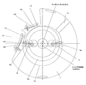
- FIG. 1 is a longitudinal sectional view showing a vane type compressor according to Embodiment 1 of the present invention.
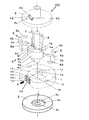
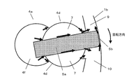
- FIG. 2 is an exploded perspective view showing a compression element of the vane type compressor.
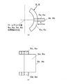
- FIG. 3 is a drawing showing a vane of this compression element, in which FIG. 3A is a plan view of the vane and FIG. 3B is a front view of the vane.
- FIG. 4 is a cross-sectional view taken along the line II of FIG.
- FIG. 5 is an arrow A view in FIGS. 2 and 4.
- an arrow indicated by a solid line indicates a flow of gas (refrigerant)
- an arrow indicated by a broken line indicates a flow of refrigerating machine oil 25.
- FIG. 1 is a longitudinal sectional view showing a vane type compressor according to Embodiment 1 of the present invention.
- FIG. 2 is an exploded perspective view showing a compression element of the vane type compressor.
- FIG. 3 is a drawing showing a
- FIGS. 1 to 5 shows a state where the rotation angle of the rotor portion 4a of the rotor shaft 4 is 90 ° as will be described later with reference to FIG.
- the vane compressor 200 according to the first embodiment will be described with reference to FIGS. 1 to 5.
- a compression element 101 and an electric element 102 that drives the compression element 101 are housed in a hermetic container 103.
- the compression element 101 is disposed at the lower part of the sealed container 103.
- the electric element 102 is disposed on the upper portion of the sealed container 103 (more specifically, above the compression element 101).
- An oil sump 104 for storing the refrigerating machine oil 25 is provided at the bottom of the sealed container 103.
- a suction pipe 26 is attached to the side surface of the sealed container 103, and a discharge pipe 24 is attached to the upper surface.
- the electric element 102 that drives the compression element 101 is constituted by, for example, a brushless DC motor.
- the electric element 102 includes a stator 21 fixed to the inner periphery of the hermetic container 103, and a rotor 22 disposed inside the stator 21 and using a permanent magnet.
- a driving force is applied to the permanent magnet of the rotor 22 by the magnetic field generated in the stator 21, The rotor 22 rotates.
- the compression element 101 sucks and compresses low-pressure gas refrigerant from the suction pipe 26 into the compression chamber, and discharges the compressed refrigerant into the sealed container 103.
- the refrigerant discharged into the sealed container 103 passes through the electric element 102 and is discharged to the outside (the high pressure side of the refrigeration cycle) from the discharge pipe 24 fixed (welded) to the upper part of the sealed container 103.
- the compression element 101 has the following elements.
- the vane type compressor 200 according to the first embodiment shows that the number of vanes is two (the first vane unit 5 and the second vane unit 6).
- Cylinder 1 The overall shape is substantially cylindrical, and both ends in the central axis direction are open. That is, the cylinder 1 has a hole whose inner peripheral surface is cylindrical and whose both ends are open. Further, a part of the cylinder inner peripheral surface 1b (inner peripheral surface of the hole) formed in a substantially cylindrical shape penetrates in the central axis direction and is beaten outward (having a convex shape on the outer peripheral side). A notch 1c is provided. And in the notch part 1c, the suction port 1a is opened from the outer peripheral surface to the cylinder inner peripheral surface 1b. A first discharge port 1d is formed at a position opposite to the suction port 1a with a nearest contact point 32, which will be described later, interposed therebetween. The first discharge port 1d is formed in the vicinity of the closest point 32 (shown in FIG. 4) and is formed on the side facing the frame 2 described later (see FIGS. 2 and 4).
- a second discharge port 1e penetrating in the radial direction is provided on the cylinder inner peripheral surface 1b at a position farther from the closest contact 32 than the first discharge port 1d. That is, the second discharge port 1e is at a position having a smaller phase angle than the first discharge port 1d (in other words, upstream of the first discharge port 1d in the vane rotation direction and upstream of the compression stroke). Is provided).
- the outlet portion of the second discharge port 1e is greatly bent so that the radial length of the second discharge port 1e is shortened. This notch portion is surrounded by a frame 2, a cylinder head 3 and a sealed container 103 which will be described later to form a discharge space 41 (shown in FIG. 4).
- the second discharge port 1e is composed of two refrigerant flow paths provided along the axial direction (that is, provided at positions where phase angles are substantially equal).
- the cross-sectional shape of each of the refrigerant channels (that is, the shape of the opening on the cylinder inner peripheral surface 1b side) is a long hole.
- the width in the circumferential direction of the second discharge port 1e is smaller than the width of the tip of the vane 5a of the first vane portion 5 and the vane 6a of the second vane portion 6 described later.
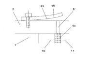
- a second discharge valve 44 and a second discharge valve presser 45 for regulating the opening degree of the second discharge valve 44 are attached to the outlet portions of the second discharge ports 1e.
- an oil return hole 1 f penetrating in the axial direction is provided in the outer peripheral portion of the cylinder 1.
- Frame 2 A cylindrical member is provided on the upper part of a substantially disk-shaped member, and its longitudinal section is substantially T-shaped.
- the substantially disk-shaped member closes (closes) one opening (the upper side in FIG. 2) of the hole of the cylinder 1.
- a vane aligner 5c of the first vane portion 5 and a vane aligner 6c of the second vane portion 6 described later are inserted into the recess 2a, and are supported (rotated and slid by the vane aligner bearing portion 2b which is the outer peripheral surface of the recess 2a. Supported freely).
- the frame 2 has a through hole so as to penetrate the substantially cylindrical member from the end surface of the substantially disk-shaped member on the cylinder 1 side.
- the through-hole is provided with a main bearing portion 2c.
- the main bearing portion 2c supports a rotating shaft portion 4b of the rotor shaft 4 described later.
- the frame 2 is formed with a first discharge port 2d communicating with the first discharge port 1d.
- first discharge valve 42 (shown only in FIG. 2) covering the opening of the first discharge port 2d and a first discharge valve 42 are provided on the surface of the substantially disk-shaped member opposite to the cylinder 1.
- a first discharge valve presser 43 (illustrated only in FIG. 2) for restricting the opening degree is attached.
- the frame 2 is provided with a communication path 2e communicating with the discharge space 41 in the axial direction.
- the recessed part 2a should just have the outer peripheral surface (vane aligner bearing part 2b) concentric with the cylinder internal peripheral surface 1b, and is not limited to a bottomed cylindrical shape. For example, you may form the recessed part 2a in the ring-shaped groove
- Cylinder head 3 A cylindrical member is provided at the lower part of a substantially disk-shaped member, and the longitudinal section is substantially T-shaped.
- the substantially disk-shaped member closes (closes) the other opening (lower side in FIG. 2) of the hole of the cylinder 1.
- On the cylinder 1 side end surface (upper surface in FIG. 2) of this substantially disk-shaped member a bottomed cylindrical concave portion 3a concentric with the cylinder inner peripheral surface 1b of the cylinder 1 is formed.
- a vane aligner 5d of the first vane portion 5 and a vane aligner 6d of the second vane portion 6 which will be described later are inserted into the recess 3a and supported by a vane aligner bearing portion 3b which is an outer peripheral surface of the recess 3a.
- the cylinder head 3 has a through hole so as to penetrate the substantially cylindrical member from the cylinder 1 side end surface of the substantially disk-shaped member.
- a main bearing 3c is provided in the through hole.
- the main bearing portion 3c supports a rotating shaft portion 4c of the rotor shaft 4 described later.
- the recess 3a only needs to have an outer peripheral surface (vane aligner bearing portion 2b) that is concentric with the cylinder inner peripheral surface 1b, and is not limited to a bottomed cylindrical shape. For example, you may form the recessed part 3a in the ring-shaped groove
- Rotor shaft 4 A substantially cylindrical rotor portion 4a that rotates in a center axis that is eccentric (displaced) from the center axis of the cylinder 1 (more specifically, the cylinder inner peripheral surface 1b) in the cylinder 1, and the rotor A rotating shaft portion 4b provided on the upper portion of the rotor portion 4a so as to be concentric with the portion 4a, and a rotating shaft portion 4c provided on the lower portion of the rotor portion 4a so as to be concentric with the rotor portion 4a.
- the rotor portion 4a, the rotating shaft portion 4b, and the rotating shaft portion 4c are formed as an integral structure.
- the rotor portion 4a is formed with a plurality of substantially cylindrical through holes (bush holding portions 4d and 4e and vane relief portions 4f and 4g) penetrating in the axial direction.
- the bush holding portion 4d and the vane relief portion 4f communicate with each other at the side surface
- the bush holding portion 4e and the vane relief portion 4g communicate with each other at the side surface portion.
- the bush holding portion 4d and the bush holding portion 4e are open on the outer peripheral portion side of the rotor portion 4a.
- the axial ends of the vane escape portion 4 f and the vane escape portion 4 g communicate with the recess 2 a of the frame 2 and the recess 3 a of the cylinder head 3.
- the bush holding portion 4d, the bush holding portion 4e, the vane relief portion 4f, and the vane relief portion 4g are disposed at substantially symmetrical positions with respect to the rotation axis of the rotor portion 4a (see FIG. 4).
- an oil pump 31 (shown only in FIG. 1) as described in, for example, Japanese Patent Application Laid-Open No. 2009-264175 is provided at the lower end of the rotor shaft 4.
- the oil pump 31 sucks the refrigeration oil 25 in the oil sump 104 using the centrifugal force of the rotor shaft 4.
- This oil pump 31 is provided in the axial center portion of the rotor shaft 4 and communicates with an oil supply passage 4h extending in the axial direction, and between the oil supply passage 4h and the recess 2a, between the oil supply passage 4i and between the oil supply passage 4h and the recess 3a. Is provided with an oil supply passage 4j.
- an oil drain hole 4k (shown only in FIG. 1) is provided at a position above the main bearing portion 3c of the rotary shaft portion 4b.
- the vane 5a, the vane aligner 5c, and the vane aligner 5d are integrally formed.
- the vane 5a is a plate-like member having a substantially square shape when viewed from the side, and the vane tip 5b (tip on the side protruding from the rotor 4a) located on the cylinder inner peripheral surface 1b side of the cylinder 1 is outward in plan view. It is formed in a convex arc shape.
- the radius of the arc shape of the vane tip 5b is configured to be substantially the same as the radius of the cylinder inner peripheral surface 1b of the cylinder 1.
- a partial ring shape (a surface facing the frame 2) that supports the vane 5a is provided on the upper surface (the surface facing the frame 2).
- a ring-shaped vane aligner 5c is provided.
- a partial ring-shaped vane aligner 5d that supports the vane 5a is provided on the lower surface (the surface facing the cylinder head 3) in the vicinity of the inner peripheral end of the vane 5a.
- the vane 5a, the vane aligner 5c, and the vane aligner 5d are arranged such that the vane longitudinal direction of the vane 5a and the normal direction of the arc of the vane tip 5b pass through the centers of the arc-shaped portions that form the vane aligners 5c and 5d. Is formed.
- Second vane portion 6 The vane 6a, the vane aligner 6c, and the vane aligner 6d are integrally formed.
- the vane 6a is a substantially quadrangular plate member in side view, and a vane tip 6b (tip on the side protruding from the rotor 4a) located on the cylinder inner peripheral surface 1b side of the cylinder 1 is outward in plan view. It is formed in a convex arc shape.
- the radius of the arc shape of the vane tip 6b is configured to be substantially equal to the radius of the cylinder inner peripheral surface 1b of the cylinder 1.
- a partial ring-shaped vane aligner 6c that supports the vane 5a is provided on the upper surface (the surface facing the frame 2) in the vicinity of the inner peripheral end of the vane tip 6b of the vane 6a.
- a partial ring-shaped vane aligner 6d that supports the vane 5a is provided on the lower surface (the surface facing the cylinder head 3) in the vicinity of the inner peripheral end of the vane 6a.
- the vane 6a, the vane aligner 6c, and the vane aligner 6d are arranged such that the vane longitudinal direction of the vane 6a and the normal direction of the arc of the vane tip 6b pass through the centers of the arc-shaped portions that form the vane aligners 6c and 6d. Is formed.
- Bushes 7 and 8 A substantially semi-cylindrical member is configured as a pair.
- the bush 7 is rotatably inserted into the bush holding portion 4d of the rotor portion 4a while sandwiching the vane 5a of the first vane portion 5.
- the bush 8 is rotatably inserted into the bush holding portion 4e of the rotor portion 4a in a state where the vane 6a of the second vane portion 6 is sandwiched. That is, when the vane 5a of the first vane part 5 slides between the bushes 7, the first vane part 5 is substantially in the centrifugal direction (the center of the cylinder inner peripheral surface 1b of the cylinder 1) with respect to the rotor part 4a.
- the vane aligners 5c, 5d, 6c, 6d, the vane aligner bearing portions 2b, 3b of the recesses 2a, 3a, the bush holding portions 4d, 4e, and the bushes 7, 8 correspond to the vane angle adjusting means in the present invention. .
- the rotor portion 4 a of the rotor shaft 4 and the cylinder inner peripheral surface 1 b of the cylinder 1 are in closest contact at one place (the closest point 32 shown in FIG. 4).
- the radius of the vane aligner bearing portions 2b and 3b is r a (see FIG. 7 described later) and the radius of the cylinder inner peripheral surface 1b is r c (see FIG. 4)
- the vane of the first vane portion 5 is used.
- the distance r v (see FIG. 3) between the outer peripheral surfaces of the aligners 5c and 5d and the vane tip 5b is set as shown in the following expression (1).
- r v r c ⁇ r a ⁇ (1)
- ⁇ is a gap between the vane tip 5b and the cylinder inner peripheral surface 1b.
- [delta] is set to r v to as small as possible to minimize a leakage of the refrigerant from the vane tip 5b.
- the relationship of the expression (1) is the same in the second vane portion 6, and the second vane is maintained while maintaining a narrow gap between the vane tip portion 6 b of the second vane portion 6 and the cylinder inner peripheral surface 1 b. The part 6 will rotate.
- the first vane portion 5 and the cylinder inner peripheral surface 1b, and the second vane portion 6 and the cylinder inner peripheral surface 1b each maintain a narrow gap, so that there are three spaces (intakes in the cylinder 1).
- a chamber 9, an intermediate chamber 10, and a compression chamber 11) are formed (shown in FIG. 4).
- a suction port 1a communicating with the low pressure side of the refrigeration cycle is opened in the suction chamber 9 through a notch 1c.
- the notch 1c is provided from the vicinity of the closest point 32 to a range of point B where the vane tip 5b of the first vane 5 and the cylinder inner peripheral surface 1b face each other. ing.
- the rotational operation of the vane type compressor 200 will be described.
- the rotating shaft portion 4b of the rotor shaft 4 receives the rotational power from the electric element 102 as the driving portion
- the rotor portion 4a rotates in the cylinder 1.
- the bush holding parts 4d and 4e arranged near the outer periphery of the rotor part 4a move on the circumference with the rotor shaft 4 as the rotation axis (center axis).
- the first vane portion 5 and the second vane portion 6 receive centrifugal force due to rotation, and the vane aligners 5c and 6c and the vane aligners 5d and 6d are pressed against the vane aligner bearing portions 2b and 3b, respectively, while sliding.
- the vane aligner bearing portions 2b and 3b rotate around the central axis.
- the vane aligner bearing portions 2b and 3b and the cylinder inner peripheral surface 1b are concentric. For this reason, the first vane portion 5 and the second vane portion 6 rotate around the center of the cylinder inner peripheral surface 1b.
- the bushes 7 and 8 are disposed in the bush holding portions 4d and 4e so that the longitudinal directions of the vane 5a of the first vane portion 5 and the vane 6a of the second vane portion 6 are directed to the cylinder center. It will rotate around 8a.
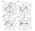
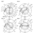
- FIG. 6 is an explanatory diagram showing the compression operation of the compression element according to Embodiment 1 of the present invention.
- FIG. 6 is a cross-sectional view taken along the line II of FIG.
- a state in which the volumes of the suction chamber 9, the intermediate chamber 10, and the compression chamber 11 change with the rotation of the rotor portion 4a (rotor shaft 4) will be described with reference to FIG.
- low-pressure refrigerant flows from the suction pipe 26 into the suction port 1a.
- the rotation angle of the rotor portion 4a (rotor shaft 4) is defined as follows.
- a state where the sliding portion (contact portion) between the first vane portion 5 and the cylinder inner peripheral surface 1b of the cylinder 1 coincides with the closest point 32 is defined as “angle 0 °”.
- angle 0 ° a state where the sliding portion (contact portion) between the first vane portion 5 and the cylinder inner peripheral surface 1b of the cylinder 1 coincides with the closest point 32
- FIG. 6 in the state of “angle 0 °”, “angle 45 °”, “angle 90 °”, and “angle 135 °”, the positions of the first vane portion 5 and the second vane portion 6 and at that time
- the state of the suction chamber 9, the intermediate chamber 10, and the compression chamber 11 is shown.
- the arrow shown in the “angle 0 °” diagram of FIG. 6 is the rotational direction of the rotor shaft 4 (clockwise in FIG. 6). However, in other drawings, an arrow indicating the rotation direction of the rotor shaft 4 is omitted.
- FIG. 6 the state after “angle 180 °” is not shown.
- the first vane portion 5 and the second vane portion 6 are switched at “angle 0 °”. This is because the same compression operation is performed from “angle 0 °” to “angle 135 °” thereafter.
- the space on the right side partitioned by the closest point 32 and the second vane portion 6 is the intermediate chamber 10 and communicates with the suction port 1a via the notch portion 1c. Inhale (refrigerant).
- the left space partitioned by the closest contact 32 and the second vane portion 6 becomes the compression chamber 11 communicating with the first discharge port 1d and the second discharge port 1e.
- the space partitioned by the first vane portion 5 and the closest contact point 32 becomes the suction chamber 9 communicating with the suction port 1a via the notch portion 1c.
- the space partitioned by the first vane unit 5 and the second vane unit 6 is an intermediate chamber 10.
- the suction chamber 9 and the intermediate chamber 10 communicate with the suction port 1a through the notch 1c. Since the volume of the intermediate chamber 10 becomes larger than that at the “angle 0 °”, the gas suction is continued.
- the space partitioned by the second vane portion 6 and the closest contact point 32 is the compression chamber 11, and the volume of the compression chamber 11 becomes smaller than that at the “angle 0 °”, and the refrigerant is compressed and its pressure gradually increases. Become.
- the first discharge valve 42 and the second discharge valve 44 are opened, and the gas in the compression chamber 11 is supplied from the first discharge port 1d to the first discharge port 1d.
- the second discharge port 1e is also discharged into the sealed container 103 through the discharge space 41 and the communication path 2e.
- the gas discharged into the sealed container 103 passes through the electric element 102 and is discharged to the outside (high pressure side of the refrigeration cycle) from the discharge pipe 24 fixed (welded) to the upper part of the sealed container 103 (see FIG. 1). (Shown with solid lines). Therefore, the pressure in the sealed container 103 is a high discharge pressure.
- FIG. 6 shows a case where the pressure in the compression chamber 11 exceeds the high pressure at an “angle of 45 °”.
- the vane tip 5b of the first vane 5 overlaps the point B on the cylinder inner peripheral surface 1b of the cylinder 1, so that the intermediate chamber 10 does not communicate with the suction port 1a. Thereby, the suction of the gas in the intermediate chamber 10 is completed.
- the volume of the intermediate chamber 10 is substantially maximum.
- the volume of the suction chamber 9 becomes larger than that at the “angle 45 °”, and the suction is continued. Since the volume of the compression chamber 11 is further smaller than that at the “angle 45 °”, the gas in the compression chamber 11 is discharged from the first discharge port 1d through the first discharge port 2d into the sealed container 103.
- the second discharge port 1e is discharged into the sealed container 103 through the discharge space 41 and the communication passage 2e.
- the volume of the intermediate chamber 10 becomes smaller than that at “angle 90 °”, and the gas pressure increases. Further, the volume of the suction chamber 9 becomes larger than that at the “angle 90 °”, and the suction is continued.
- the vane 6a of the second vane portion 6 passes through the second discharge port 1e, and the second discharge port 1e opens into the intermediate chamber 10, the second discharge valve 44 has a pressure difference. Close by.
- the first discharge port 1d remains open to the compression chamber 11, the first discharge valve 42 is open. Since the volume of the compression chamber 11 becomes smaller than that at the “angle 90 °”, the gas in the compression chamber 11 is discharged from the first discharge port 1d into the sealed container 103 through the first discharge port 2d.
- the volume of the suction chamber 9 gradually increases due to the rotation of the rotor portion 4a (rotor shaft 4), and continues to suck gas. Thereafter, the flow proceeds to the intermediate chamber 10, but the volume gradually increases to the middle, and the gas suction is further continued. On the way, the volume of the intermediate chamber 10 is maximized and is not communicated with the suction port 1a. Thereafter, the volume of the intermediate chamber 10 gradually decreases and compresses the gas. Thereafter, the intermediate chamber 10 moves to the compression chamber 11 and continues to compress the gas. The gas compressed to a predetermined pressure pushes up the first discharge valve 42 through the first discharge port 1d and the first discharge port 2d, and is discharged into the sealed container 103 and the second discharge port.
- the second discharge valve 44 is pushed up and discharged into the sealed container 103 through the discharge space 41 and the communication path 2e. Thereafter, when the vane 6a of the second vane portion 6 passes through the second discharge port 1e, the second discharge valve 44 is closed, and the compressed gas in the compression chamber 11 is transferred to the first discharge port 1d and the first discharge port 1d. It is discharged into the sealed container 103 only from the discharge port 2d.
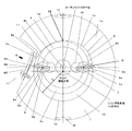
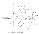
- FIG. 7 is an explanatory diagram for explaining the rotation operation of the vane aligner according to the first embodiment of the present invention, and is a cross-sectional view taken along the line II-II in FIG.
- movement of the vane aligners 5c and 6c is shown.
- the arrow shown in the “angle 0 °” diagram of FIG. 7 is the rotation direction of the vane aligners 5c and 6c (clockwise in FIG. 7).
- the arrows indicating the rotation direction of the vane aligners 5c and 6c are omitted.
- the rotation of the rotor shaft 4 causes the vane 5a of the first vane portion 5 and the vane 6a of the second vane portion 6 to rotate around the central axis of the cylinder 1 (see FIG. 6). Accordingly, as shown in FIG. 7, the vane aligners 5c and 6c are supported by the vane aligner bearing portion 2b and rotate around the central axis of the cylinder inner peripheral surface 1b in the recess 2a. This operation is the same for the vane aligners 5d and 6d that rotate in the recess 3a supported by the vane aligner bearing portion 2b.
- the refrigeration oil 25 is sucked up from the oil sump 104 by the oil pump 31 and sent out to the oil supply path 4h, as indicated by broken line arrows in FIG.
- the refrigerating machine oil 25 sent out to the oil supply passage 4h passes through the oil supply passage 4i and is sent out to the recess 3a of the cylinder head 3 through the recess 2a of the frame 2 and the oil supply passage 4j.
- the refrigerating machine oil 25 fed to the recesses 2a and 3a lubricates the vane aligner bearing portions 2b and 3b, and a part thereof is supplied to the vane relief portions 4f and 4g communicating with the recesses 2a and 3a.
- the pressure in the sealed container 103 is a high discharge pressure
- the pressures in the recesses 2a and 3a and the vane relief portions 4f and 4g are also discharge pressures.
- a part of the refrigerating machine oil 25 fed to the recesses 2 a and 3 a is supplied to the main bearing portion 2 c of the frame 2 and the main bearing portion 3 c of the cylinder head 3.
- the refrigerating machine oil 25 sent out to the vane relief portions 4f and 4g flows as follows.
- FIG. 8 is a main part enlarged view showing the vicinity of the vane of the vane part according to the first embodiment of the present invention.
- FIG. 8 is an enlarged view of the main part showing the vicinity of the vane 5a of the first vane part 5 in FIG. 4, and the arrows shown by solid lines in the drawing indicate the flow of the refrigerating machine oil 25.
- the refrigerating machine oil 25 lubricates the sliding portion between the side surface of the vane 5a and the bush 7.
- the pressure difference and the centrifugal force are sent to the suction chamber 9 and the intermediate chamber 10.
- the refrigerating machine oil 25 is sent out to the suction chamber 9 and the intermediate chamber 10 by the pressure difference and the centrifugal force while lubricating the sliding portion between the bush 7 and the bush holding portion 4d of the rotor shaft 4.
- a part of the refrigerating machine oil 25 fed to the intermediate chamber 10 flows into the suction chamber 9 while sealing the gap between the vane tip 5b and the cylinder inner peripheral surface 1b of the cylinder 1.
- FIG. 8 shows the case where the space partitioned by the first vane unit 5 is the suction chamber 9 and the intermediate chamber 10, the rotation proceeds and the space partitioned by the first vane unit 5 is the intermediate chamber.
- the pressure in the compression chamber 11 reaches the same discharge pressure as the pressure of the vane escape portion 4f, the refrigerating machine oil 25 is sent out toward the compression chamber 11 by centrifugal force.
- the above operation is shown for the first vane unit 5, the same operation is performed in the second vane unit 6.
- the refrigerating machine oil 25 supplied to the main bearing portion 2 c is discharged into the space above the frame 2 through the gap of the main bearing portion 2 c, and then the outer periphery of the cylinder 1. It is returned to the oil sump 104 through an oil return hole 1f provided in the section. Further, the refrigerating machine oil 25 supplied to the main bearing portion 3c is returned to the oil sump 104 through the gap of the main bearing portion 3c. Further, the refrigerating machine oil 25 sent to the suction chamber 9, the intermediate chamber 10 and the compression chamber 11 through the vane relief portions 4f and 4g also finally flows into the frame 2 from the first discharge port 2d and the communication passage 2e together with the gas.
- a general vane compressor having only the first discharge port 1d as a discharge port (hereinafter referred to as the first embodiment).
- a known vane compressor having a different configuration is simply referred to as a general vane compressor).
- the flow channel width (the length in the radial direction) of the compression chamber 11 at the position of the first discharge port 1d is extremely small, and the flow channel area is also small.
- the gas in the compression chamber 11 has a high flow velocity before flowing into the first discharge port 1d, and the pressure loss increases regardless of the size of the first discharge port 1d.
- the second discharge port 1e is provided at a position having a smaller phase angle than the first discharge port 1d.
- the flow channel width (flow channel area) of the compression chamber 11 at the position 1e is large. For this reason, since the flow velocity before the gas in the compression chamber 11 flows into the second discharge port 1e also becomes slow, the pressure loss can be reduced.
- the discharge port that opens into the compression chamber 11 is only the first discharge port 1d, as shown by "Angle 135" in FIG. .
- the flow rate of the gas discharged from the compression chamber 11 is also considerably reduced, so that the flow rate when the gas in the compression chamber 11 flows into the first discharge port 1d is not large and the pressure loss is small.
- the discharge loss can be made smaller than that of a general vane compressor.
- FIG. 9 is an explanatory diagram for explaining the behavior of the gas when the vane passes through the second discharge port.
- FIG. 9 is a cross-sectional view of the main part around the vane 6a of the second vane 6 when the vane tip 6b of the second vane 6 is at the position of the second discharge port 1e. More specifically, FIG. 9A shows the shape of the vane tip 6b shown in the first embodiment (the radius of the arc shape of the vane tip 6b is substantially equal to the radius of the cylinder inner peripheral surface 1b). ) Is shown.
- FIG. 9B shows a vane compressor having a general shape of the vane tip 6b (for example, a vane compressor described in Patent Document 1 or Patent Document 2). The case where it is the shape of the thing formed in the formed vane groove so that sliding is possible is shown.
- the radius of the arc shape of the vane tip portion 6b of the second vane portion 6 is substantially equal to the radius of the cylinder inner peripheral surface 1b.
- the radius is the same.
- tip part 6b of the 2nd vane part 6 and the cylinder internal peripheral surface 1b becomes the micro clearance gap (delta) over the whole width
- the circumferential width of the second discharge port 1e (more specifically, the opening formed in the cylinder inner peripheral surface 1b) is smaller than the width of the vane tip 6b of the second vane 6.
- the radius of the arc shape of the vane tip portion 6b of the second vane portion 6 is shown. Is configured to be considerably smaller than the radius of the cylinder inner peripheral surface 1b. Therefore, the gap between the vane tip 6b and the cylinder inner peripheral surface 1b is a contact position 51 between the vane tip 6b and the cylinder inner peripheral surface 1b (the axial direction in which the discharge port 1e of the cylinder inner peripheral surface 1b is not provided). And the position where the vane tip 6b contacts).
- the radius of the arc shape forming the vane tip 6b (and 5b) is set to be larger than the radius of the cylinder inner peripheral surface 1b.
- the radius of the rotor portion 4a and the center of the cylinder inner peripheral surface 1b are eccentric in the general vane type compressors described in Patent Document 1 and Patent Document 2, and the vane is the center of the rotor 44a. This is because of rotating around the axis.
- the arc-shaped radius of the vane tip 6b (and 5b) is set to the radius of the cylinder inner peripheral surface 1b. This is because it needs to be smaller.
- the first vane unit 5 and the second vane unit 6 are configured to rotate about the center of the cylinder inner peripheral surface 1b as a rotation axis.
- the arc-shaped normal line of the vane tip portions 5b and 6b and the normal line of the cylinder inner peripheral surface 1b can almost always coincide with each other to perform the compression operation), so that the vane tip portion 6b (and 5b)
- the radius of the circular arc shape and the radius of the cylinder inner peripheral surface 1b can be set to be equal or close to each other.
- the gas leakage when the first vane unit 5 and the second vane unit 6 pass through the second discharge port 1e does not increase. Since pressure loss can be reduced, a highly efficient vane compressor 200 with extremely low loss can be obtained.
- the circumferential width of the second discharge port 1e (more specifically, the opening formed in the cylinder inner peripheral surface 1b) is set to the width of the vane tip 5b of the first vane 5.
- the width and the width of the vane tip portion 6b of the second vane portion 6 are formed smaller than each other, the circumferential width of the second discharge port 1e (more specifically, the opening formed in the cylinder inner peripheral surface 1b) is as follows. The width of the vane tip 5b of the first vane 5 and the width of the vane tip 6b of the second vane 6 can be increased.
- the relationship between the cross-sectional area of the first discharge port 1d and the cross-sectional area of the second discharge port 1e is not particularly mentioned.
- the following structure may be used. That is, since the flow passage area of the compression chamber 11 located at the second discharge port 1e is larger than the flow passage area of the compression chamber 11 located at the first discharge port 1d, the pressure loss is effectively reduced. Therefore, it is better to increase the flow rate discharged from the second discharge port 1e as much as possible.
- the cross-sectional area of the second discharge port 1e is preferably larger than the cross-sectional area of the first discharge port 1d.
- the second discharge port 1e is configured by two refrigerant flow paths.
- this is merely an example, and the configuration of the second discharge port 1e is not limited to the above configuration. Absent.
- FIG. 10 is an explanatory diagram illustrating another example of the second discharge port of the vane compressor according to the first embodiment.
- FIG. 10 is a view A in FIG. 2 and FIG.
- the second discharge port 1e may be constituted by one refrigerant flow path.
- the second discharge port 1e may be composed of three or more refrigerant channels.
- the cross-sectional shape of the second discharge port 1e (when the second discharge port 1e is formed of a plurality of refrigerant flow paths, the cross-sectional shape of each refrigerant flow path) is not limited to the long hole shape. However, any shape may be used as long as the width in the circumferential direction is equal to or smaller than the width of the vane tip 5b of the first vane 5 and the width of the vane tip 6b of the second vane 6.
- the outflow destination of the gas flowing into the second discharge port from the compression chamber 11 is not limited to the above configuration.
- the second discharge port 1e is configured not to penetrate the outer peripheral side of the cylinder 1, and a through hole communicating with the second discharge port 1e is formed in at least one of the frame 2 and the cylinder head 3, and this through hole is formed.
- the gas that has flowed from the compression chamber 11 into the second discharge port may be allowed to flow out into the sealed container 103.
- the second discharge valve 44 and the second discharge valve presser 45 are provided at the outlet portion of the through hole. Even in such a configuration, the same effect can be obtained by the same operation as described above.
- FIG. 11 is an explanatory diagram showing another example of the first discharge port of the vane compressor according to the first embodiment.
- FIG. 11 is a cross-sectional view taken along the line II in FIG. 1, and shows a state at a rotation angle of 90 ° in FIG.
- the first discharge port 1d is configured to penetrate the cylinder inner peripheral surface 1b in the radial direction in the same manner as the second discharge port 1e. For this reason, the 1st discharge valve 42 and the 1st discharge valve holder 43 are attached to the exit part of the 1st discharge port 1d. Even in such a configuration, the same effect can be obtained by the same operation as described above.
- the vane longitudinal direction of the vanes 5a and 6a and the normal direction of the arc of the vane tip portions 5b and 6b are substantially the same direction. It was. Not only this but the 1st vane part 5 and the 2nd vane part 6 may be constituted like Drawing 12, for example.
- FIG. 12 is a plan view showing still another example of the vane of the compression element according to Embodiment 1 of the present invention.
- C indicates the vane longitudinal direction of the vanes 5a and 6a.
- D has shown the normal line direction of the circular arc of the vane front-end
- the compression operation can be performed in a state where the arcs of the vane tip portions 5b and 6b and the normal line of the cylinder inner peripheral surface 1b of the cylinder 1 always coincide with each other during the rotation. Therefore, the same effect as described above can be obtained. Further, the arc length of the vane tip portions 5b and 6b (that is, the width of the vane tip portions 5b and 6b) can be increased, and the cross-sectional area of the second discharge port 1e and the opening portion on the compression chamber 11 side can be increased. There is also an effect that the circumferential width can be further increased.
- Embodiment 2 FIG.
- the vane compressor 200 having only one discharge port (second discharge port 1e) formed at a position having a smaller phase angle than the first discharge port 1d has been described.
- the second discharge ports may be formed at positions having a smaller phase angle than the first discharge port 1d. Note that items not particularly described in the second embodiment are the same as those in the first embodiment, and the same functions and configurations are described using the same reference numerals.
- FIG. 14 is a cross-sectional view showing a compression element of the vane type compressor according to the second embodiment.
- FIG. 14 is a cross-sectional view taken along the line II in FIG. 1, and shows a state at a rotation angle of 90 ° in FIG.
- the vane type compressor 200 according to the second embodiment includes two second discharge ports (a second discharge port 1e and a second discharge port 1g). That is, the vane type compressor 200 according to the second embodiment is obtained by adding the second discharge port 1g to the configuration of the vane type compressor 200 shown in the first embodiment.
- the second discharge port 1g is provided in a radial direction at a position having a smaller phase angle than the second discharge port 1e, and the circumferential width of the second discharge port 1g is the first vane portion. 5 is smaller than the width of the vane tip portion 5 b and the width of the vane tip portion 6 b of the second vane portion 6. Further, the third discharge valve 46 and a third discharge valve presser 47 for regulating the opening degree of the third discharge valve 46 are attached to the outlet portion of the second discharge port 1g.
- the flow path width of the compression chamber 11 at the position of the second discharge port 1g ( The flow path area) is larger than the flow path width (flow path area) of the compression chamber 11 at the position of the second discharge port 1e.
- FIG. 15 is an explanatory view showing the compression operation of the compression element according to Embodiment 2 of the present invention, and is a cross-sectional view taken along the line II of FIG.
- the gas discharge operation from the compression chamber 11 will be described with reference to FIG.
- FIG. 15 shows a case where the pressure in the compression chamber 11 exceeds the high pressure at an “angle of 45 °”.
- the second vane portion 6 passes through the second discharge port 1 g, and the second discharge port 1 g opens into the intermediate chamber 10. 46 is closed by the pressure difference.
- the gas in the compression chamber 11 is discharged from the first discharge port 1d and the second discharge port 1e. .
- the second vane portion 6 passes through the second discharge port 1 e, and the second discharge port 1 e opens into the intermediate chamber 10, so that the second discharge valve 44 is closed by the pressure difference.
- the first discharge port 1d is open to the compression chamber 11, the gas in the compression chamber 11 is discharged from the first discharge port 1d.
- the flow passage area of the compression chamber 11 at the position of the second discharge port 1g is the compression chamber 11 at the position of the second discharge port 1e. Therefore, the flow velocity before the gas in the compression chamber 11 flows into the second discharge port 1g is slower than that in the first embodiment. For this reason, pressure loss can be made smaller.
- the discharge port that opens to the compression chamber 11 is connected to the first discharge port 1d and the second discharge port as shown by “angle 90 °” in FIG. At this time, the flow rate of gas discharged from the compression chamber 11 has also decreased to some extent, so that the flow rate when the gas in the compression chamber 11 flows into the second discharge port 1e is set. It can be slower than the first mode and pressure loss can be reduced.
- the cross-sectional areas of the first discharge port 1d, the second discharge port 1e, and the second discharge port 1e are not particularly mentioned, but may be configured as follows, for example. That is, the flow area of the compression chamber 11 located at the second discharge port 1g is larger than the flow area of the compression chamber 11 located at the second discharge port 1e, and the compression position located at the second discharge port 1e. The flow passage area of the chamber 11 is larger than the flow passage area of the compression chamber 11 located at the first discharge port 1d.
- the first discharge port 1d, the second discharge port 1e, and the second discharge port 1g are preferably set in the order of smaller cross-sectional areas. That is, in order to effectively reduce the pressure loss, it is preferable to increase the cross-sectional area of the discharge port with a smaller phase angle.
- the vane compressor 200 including two second discharge ports (second discharge port 1e and second discharge port 1g) having different phase angles has been described.
- three or more second discharge ports may be provided.
- Embodiment 3 In the first embodiment and the second embodiment, the compression chamber 11 side opening of the second discharge port opens in the cylinder inner peripheral surface 1b. Not only this but the compression chamber 11 side opening part of the 2nd discharge port may open in the following positions.
- items that are not particularly described are the same as those in Embodiment 1 or Embodiment 2, and the same functions and configurations are described using the same reference numerals.
- FIG. 16 is a cross-sectional view showing a compression element of the vane type compressor according to the third embodiment.
- FIG. 16 is a cross-sectional view taken along the line II in FIG. 1, and shows a state at a rotation angle of 90 ° in FIG.
- FIG. 17 is a sectional view taken along line III-III in FIG.
- the vane type compressor 200 according to the third embodiment will be described with reference to FIGS. 16 and 17.
- the second discharge port 2 f is provided to penetrate the frame 2 in the axial direction, and the circumferential direction The width is smaller than the width of the vane 5 a of the first vane part 5 and the vane 6 a of the second vane part 6.
- a second discharge valve 44 and a second discharge valve presser 45 are attached to the outlet portion of the second discharge port 2f.
- the operation of discharging gas from the compression chamber 11 of the vane type compressor 200 according to the third embodiment is the same as that of the first embodiment.
- the behavior of the gas when the first vane unit 5 or the second vane unit 6 passes through the second discharge port 2f is as follows. As shown in FIG. 17, since the circumferential width of the second discharge port 2f is smaller than the width of the vane 6a, when the second vane portion 6 is at the position of the second discharge port 2f, Gas leakage from the compression chamber 11 to the intermediate chamber 10 through the second discharge port 2f is sealed at the end face of the vane 6a and the end face of the frame 2. For this reason, as in the first embodiment, the leakage from the compression chamber 11 to the intermediate chamber 10 can be extremely reduced.
- the first vane unit 5 and the second vane unit 6 are the first vane unit 6 as in the first and second embodiments. Since the pressure loss can be reduced without increasing the leakage when passing through the second discharge port 2f, a highly efficient vane compressor 200 with very little loss can be obtained.
- the second discharge port 2f is formed in the frame 2 (that is, the opening on the compression chamber 11 side of the second discharge port 2f is in the frame 2). Since it is open), the following effects can also be obtained.
- the opening on the compression chamber 11 side of the second discharge port (the second discharge port 1e or the second discharge port 1g) opens to the cylinder inner peripheral surface 1b. Therefore, it is necessary to set the radius of the arc shape of the vane tip portions 5b and 6b and the radius of the cylinder inner peripheral surface 1b to be equal.
- the first vane portion 5 and the second vane portion 6 are rotated around the center of the cylinder inner peripheral surface 1b (in other words, the arc-shaped normal line of the vane tip portions 5b and 6b and the cylinder inner periphery). It was necessary to provide a vane angle adjusting means so that the normal line of the surface 1b is always substantially coincident and the compression operation is performed.
- the leakage of gas from the compression chamber 11 to the intermediate chamber 10 via the second discharge port 2f is caused by the first vane portion 5 and the second vane portion. Since it seals between the end surface of 6 and the flame
- the second discharge port 2f is provided in the frame 2, but it may be provided in the cylinder head 3 or in both the frame 2 and the cylinder head 3.
- the circumferential width of the second discharge port 2f (more specifically, the opening on the compression chamber 11 side) is set to the width of the vane 5a of the first vane portion 5 and the second vane.
- the width of the second discharge port 2f (more specifically, the opening on the compression chamber 11 side) in the circumferential direction is smaller than the width of the vane 6a of the section 6, the width of the vane 5a of the first vane section 5 is The width of the second vane portion 6 can be increased up to the same width as the vane 6a.
- two second discharge ports may be provided, and of course, three or more second discharge ports may be provided.
- the vane aligner may be formed in a ring shape instead of a partial ring shape.
- the oil pump 31 using the centrifugal force of the rotor shaft 4 has been described.
- any oil pump may be used.
- it is described in Japanese Patent Application Laid-Open No. 2009-62820.
- a positive displacement pump may be used as the oil pump 31.
- the vane angle adjusting means described in the first to third embodiments is merely an example, and the vane angle adjusting means is not limited to this configuration. It is also possible to carry out the present invention using a known vane angle adjusting means.
- a vane type compressor described in Japanese Patent Application Laid-Open No. 2000-352390 the interior of the rotor portion is made hollow, A fixed shaft that rotatably supports the vane at the center of the inner peripheral surface of the cylinder is disposed, and the vane is held via a bush in the vicinity of the outer peripheral portion of the rotor portion so that the vane can swing relative to the rotor portion. It is good also as composition to do.
- all the second discharge ports are formed on the same member. It is not limited to this.
- a part of the second discharge port may have an opening on the compression chamber 11 side that opens to the cylinder inner peripheral surface 1b (for example, the configuration of the second embodiment).
- the remaining second discharge port may have an opening on the compression chamber 11 side that opens to at least one of the frame 2 and the cylinder head 3.
- the vane 5a and the vane aligners 5c and 5d are integrally formed, and the vane 6a and the vane aligners 6c and 6d are integrally formed.
- the longitudinal direction of the vanes 5a and 6a and the normal line of the outer peripheral surface of the vane aligners 5c, 5d, 6c, and 6f can maintain a constant angle, they may be formed separately.
- the vane 105 corresponding to the vanes 5a and 6a and the vane aligner 106 corresponding to the vane aligners 5c, 5d, 6c, and 6d may be formed separately.
- the convex part 105a of the vane 105 may be inserted in the recessed part 106a of the vane aligner 106, and the vane 105 and the vane aligner 106 may be attached integrally. At this time, the two may be connected to the vane aligner 106 so that the vane 105 is slidable in the longitudinal direction.
Abstract
Priority Applications (4)
| Application Number | Priority Date | Filing Date | Title |
|---|---|---|---|
| CN201280055578.6A CN103930677B (zh) | 2012-01-11 | 2012-12-12 | 叶片型压缩机 |
| US14/350,989 US9388807B2 (en) | 2012-01-11 | 2012-12-12 | Vane compressor having a second discharge port that includes an opening portion to a compression space |
| JP2013553219A JP5774134B2 (ja) | 2012-01-11 | 2012-12-12 | ベーン型圧縮機 |
| EP12865289.8A EP2803863B1 (fr) | 2012-01-11 | 2012-12-12 | Compresseur du type à palettes |
Applications Claiming Priority (2)
| Application Number | Priority Date | Filing Date | Title |
|---|---|---|---|
| JP2012003257 | 2012-01-11 | ||
| JP2012-003257 | 2012-01-11 |
Publications (1)
| Publication Number | Publication Date |
|---|---|
| WO2013105386A1 true WO2013105386A1 (fr) | 2013-07-18 |
Family
ID=48781346
Family Applications (1)
| Application Number | Title | Priority Date | Filing Date |
|---|---|---|---|
| PCT/JP2012/082143 WO2013105386A1 (fr) | 2012-01-11 | 2012-12-12 | Compresseur du type à palettes |
Country Status (5)
| Country | Link |
|---|---|
| US (1) | US9388807B2 (fr) |
| EP (1) | EP2803863B1 (fr) |
| JP (1) | JP5774134B2 (fr) |
| CN (1) | CN103930677B (fr) |
| WO (1) | WO2013105386A1 (fr) |
Cited By (1)
| Publication number | Priority date | Publication date | Assignee | Title |
|---|---|---|---|---|
| JP2019518905A (ja) * | 2016-06-22 | 2019-07-04 | ピエルブルグ ポンプ テクノロジー ゲーエムベーハーPierburg Pump Technology Gmbh | 乾式運転羽根ガスポンプ |
Families Citing this family (8)
| Publication number | Priority date | Publication date | Assignee | Title |
|---|---|---|---|---|
| WO2015193963A1 (fr) * | 2014-06-17 | 2015-12-23 | 三菱電機株式会社 | Compresseur, équipement à cycle de réfrigération, et climatiseur |
| KR102243681B1 (ko) * | 2014-08-13 | 2021-04-23 | 엘지전자 주식회사 | 스크롤 압축기 |
| CN106401967B (zh) * | 2016-10-17 | 2019-03-19 | 珠海格力节能环保制冷技术研究中心有限公司 | 旋转式压缩机 |
| EP3315782A1 (fr) * | 2016-10-25 | 2018-05-02 | Entecnia Consulting, S.L.U. | Pompe à vide |
| KR20190132020A (ko) * | 2018-05-18 | 2019-11-27 | 현대자동차주식회사 | 내측링을 구비한 오일펌프 |
| KR102227090B1 (ko) * | 2019-02-22 | 2021-03-12 | 엘지전자 주식회사 | 베인 로터리 압축기 |
| KR102191124B1 (ko) | 2019-02-28 | 2020-12-15 | 엘지전자 주식회사 | 베인 로터리 압축기 |
| CN110863990B (zh) * | 2019-11-19 | 2021-06-04 | 珠海格力节能环保制冷技术研究中心有限公司 | 压缩机、空调器 |
Citations (10)
| Publication number | Priority date | Publication date | Assignee | Title |
|---|---|---|---|---|
| JPS5690490U (fr) * | 1979-12-14 | 1981-07-18 | ||
| JPS56150886U (fr) * | 1980-04-14 | 1981-11-12 | ||
| JPS5867996U (ja) * | 1981-11-02 | 1983-05-09 | 日産自動車株式会社 | ロ−タリ−ベ−ンコンプレツサ |
| JPS6373593U (fr) * | 1986-11-04 | 1988-05-17 | ||
| JPH06501758A (ja) * | 1990-06-07 | 1994-02-24 | エドワーズ,トーマス・シー | ベーンの二軸方向の動きを非摩擦状態に制御する回転式ベーン機械 |
| JP2000352390A (ja) | 1999-06-08 | 2000-12-19 | Hiroyoshi Ooka | ベーン軸支型回転圧縮機 |
| JP2007309281A (ja) | 2006-05-22 | 2007-11-29 | Matsushita Electric Ind Co Ltd | ベーンロータリ型圧縮機 |
| JP2008014227A (ja) | 2006-07-06 | 2008-01-24 | Calsonic Compressor Inc | 気体圧縮機 |
| JP2009062820A (ja) | 2007-09-04 | 2009-03-26 | Mitsubishi Electric Corp | 密閉形ロータリ圧縮機 |
| JP2009264175A (ja) | 2008-04-23 | 2009-11-12 | Mitsubishi Electric Corp | 冷媒圧縮機 |
Family Cites Families (31)
| Publication number | Priority date | Publication date | Assignee | Title |
|---|---|---|---|---|
| GB191026718A (en) | 1910-11-17 | 1911-08-17 | Albert Bertram Lunn | Improvements in or relating to Means for Separating and Supporting the Bows of Cape-cart Hoods and the like. |
| US1291618A (en) | 1916-09-11 | 1919-01-14 | Willard M Mcewen | Combined fluid pump and motor. |
| US1339723A (en) | 1916-10-12 | 1920-05-11 | Walter J Piatt | Rotary pump |
| US1444269A (en) | 1920-11-01 | 1923-02-06 | Walter J Piatt | Rotary pump |
| GB244181A (en) | 1924-09-13 | 1925-12-14 | William Joe Stern | Improvements in and connected with rotary pump machines |
| US2044873A (en) | 1933-11-21 | 1936-06-23 | Cecil J Beust | Rotary compressor |
| CH181039A (de) | 1935-01-28 | 1935-11-30 | Rotorkompressoren A G | Rotationskompressor mit in einem Gehäuse mit zylindrischer Bohrung exzentrisch zur Zylinderachse beidseitig gelagertem zylindrischem Rotor. |
| DE874944C (de) | 1951-02-17 | 1953-04-27 | Heinz Knebel | Rotationskompressor |
| JPS5148883B2 (fr) | 1973-04-18 | 1976-12-23 | ||
| JPS51128704A (en) | 1975-05-02 | 1976-11-09 | Toyota Motor Corp | Rotary vane pump |
| JPS5260911A (en) | 1975-11-14 | 1977-05-19 | Hitachi Ltd | Pumping motor |
| JPS5629001A (en) | 1979-08-18 | 1981-03-23 | Masaichi Hashino | Rotary piston mechanism |
| JPS5690490A (en) | 1979-12-19 | 1981-07-22 | Fujitsu Ltd | Memory change-over control system |
| JPS56129795A (en) | 1980-03-12 | 1981-10-12 | Nippon Soken Inc | Rotary compressor |
| JPS56150886A (en) | 1980-04-23 | 1981-11-21 | Nippon Telegr & Teleph Corp <Ntt> | Oscillating frequency stabilized semiconductor laser device |
| JPS5867996A (ja) | 1981-10-20 | 1983-04-22 | Sanyo Electric Co Ltd | 送風装置 |
| JPS5870087A (ja) | 1981-10-21 | 1983-04-26 | Kishino Masahide | シリンダ−内壁に同心円的に回転する翼を持つ回転ピストン圧縮機 |
| JPS601389A (ja) | 1983-06-16 | 1985-01-07 | Toyoda Autom Loom Works Ltd | 低吐出脈動圧縮機 |
| DE8434465U1 (de) | 1984-11-24 | 1986-03-27 | Robert Bosch Gmbh, 7000 Stuttgart | Flügelabdichtung in Flügelzellenpumpen |
| JPS63131883A (ja) | 1986-11-21 | 1988-06-03 | Eagle Ind Co Ltd | ベ−ンポンプ |
| US4958995A (en) | 1986-07-22 | 1990-09-25 | Eagle Industry Co., Ltd. | Vane pump with annular recesses to control vane extension |
| JPS6373593A (ja) | 1986-09-16 | 1988-04-04 | 日立化成工業株式会社 | セラミツク多層配線板の製造法 |
| JP2812022B2 (ja) | 1991-11-12 | 1998-10-15 | 松下電器産業株式会社 | バイパス弁装置を備えた多段気体圧縮機 |
| US5536153A (en) | 1994-06-28 | 1996-07-16 | Edwards; Thomas C. | Non-contact vane-type fluid displacement machine with lubricant separator and sump arrangement |
| JPH08247064A (ja) | 1995-03-07 | 1996-09-24 | Daikin Ind Ltd | スイングピストン形圧縮機 |
| JPH08247063A (ja) | 1995-03-07 | 1996-09-24 | Daikin Ind Ltd | スイングピストン形圧縮機 |
| US6026649A (en) | 1996-04-11 | 2000-02-22 | Matsushita Electric Industrial Co., Ltd. | Compressor provided with refrigerant and lubricant in specified relationship |
| TW385332B (en) | 1997-02-27 | 2000-03-21 | Idemitsu Kosan Co | Refrigerating oil composition |
| JP5431805B2 (ja) | 2009-06-24 | 2014-03-05 | 富士フイルム株式会社 | 組成物、化合物及び被膜形成方法 |
| JP5366856B2 (ja) * | 2010-02-17 | 2013-12-11 | 三菱電機株式会社 | ベーンロータリ型流体装置及び圧縮機 |
| JP5637755B2 (ja) | 2010-07-12 | 2014-12-10 | 三菱電機株式会社 | ベーン型圧縮機 |
-
2012
- 2012-12-12 CN CN201280055578.6A patent/CN103930677B/zh active Active
- 2012-12-12 EP EP12865289.8A patent/EP2803863B1/fr active Active
- 2012-12-12 WO PCT/JP2012/082143 patent/WO2013105386A1/fr active Application Filing
- 2012-12-12 US US14/350,989 patent/US9388807B2/en active Active
- 2012-12-12 JP JP2013553219A patent/JP5774134B2/ja active Active
Patent Citations (10)
| Publication number | Priority date | Publication date | Assignee | Title |
|---|---|---|---|---|
| JPS5690490U (fr) * | 1979-12-14 | 1981-07-18 | ||
| JPS56150886U (fr) * | 1980-04-14 | 1981-11-12 | ||
| JPS5867996U (ja) * | 1981-11-02 | 1983-05-09 | 日産自動車株式会社 | ロ−タリ−ベ−ンコンプレツサ |
| JPS6373593U (fr) * | 1986-11-04 | 1988-05-17 | ||
| JPH06501758A (ja) * | 1990-06-07 | 1994-02-24 | エドワーズ,トーマス・シー | ベーンの二軸方向の動きを非摩擦状態に制御する回転式ベーン機械 |
| JP2000352390A (ja) | 1999-06-08 | 2000-12-19 | Hiroyoshi Ooka | ベーン軸支型回転圧縮機 |
| JP2007309281A (ja) | 2006-05-22 | 2007-11-29 | Matsushita Electric Ind Co Ltd | ベーンロータリ型圧縮機 |
| JP2008014227A (ja) | 2006-07-06 | 2008-01-24 | Calsonic Compressor Inc | 気体圧縮機 |
| JP2009062820A (ja) | 2007-09-04 | 2009-03-26 | Mitsubishi Electric Corp | 密閉形ロータリ圧縮機 |
| JP2009264175A (ja) | 2008-04-23 | 2009-11-12 | Mitsubishi Electric Corp | 冷媒圧縮機 |
Cited By (2)
| Publication number | Priority date | Publication date | Assignee | Title |
|---|---|---|---|---|
| JP2019518905A (ja) * | 2016-06-22 | 2019-07-04 | ピエルブルグ ポンプ テクノロジー ゲーエムベーハーPierburg Pump Technology Gmbh | 乾式運転羽根ガスポンプ |
| US10995757B2 (en) | 2016-06-22 | 2021-05-04 | Pierburg Pump Technology Gmbh | Dry-running gas vane pump having a first fluid outlet and a second fluid outlet associated with the pump chamber with the second fluid outlet permanently open to atmosphere without being impeded |
Also Published As
| Publication number | Publication date |
|---|---|
| JP5774134B2 (ja) | 2015-09-02 |
| US9388807B2 (en) | 2016-07-12 |
| EP2803863A4 (fr) | 2015-09-16 |
| JPWO2013105386A1 (ja) | 2015-05-11 |
| CN103930677A (zh) | 2014-07-16 |
| US20140286807A1 (en) | 2014-09-25 |
| EP2803863B1 (fr) | 2019-04-03 |
| EP2803863A1 (fr) | 2014-11-19 |
| CN103930677B (zh) | 2016-08-24 |
Similar Documents
| Publication | Publication Date | Title |
|---|---|---|
| JP5774134B2 (ja) | ベーン型圧縮機 | |
| US7563084B2 (en) | Rotary fluid machine | |
| KR101423009B1 (ko) | 베인형 압축기 | |
| WO2013105129A1 (fr) | Compresseur de type à ailettes | |
| US8366424B2 (en) | Rotary fluid machine with reverse moment generating mechanism | |
| JP5777733B2 (ja) | ベーン型圧縮機 | |
| WO2013105131A1 (fr) | Compresseur de type à ailettes | |
| JP5932608B2 (ja) | ベーン型圧縮機 | |
| KR102310348B1 (ko) | 로터리 압축기 | |
| JP6099550B2 (ja) | ベーン型2段圧縮機 | |
| WO2009090888A1 (fr) | Machine rotative à fluide | |
| JP2013142351A (ja) | ベーン型圧縮機 | |
| JP5932675B2 (ja) | ベーン型圧縮機 | |
| JP2015113731A (ja) | 気体圧縮機 | |
| JP5921456B2 (ja) | ベーン型圧縮機 | |
| JP5661204B2 (ja) | ベーン型圧縮機 | |
| JP5657143B2 (ja) | ベーン型圧縮機 | |
| WO2015049905A1 (fr) | Compresseur à palette | |
| WO2014167708A1 (fr) | Compresseur à palettes | |
| JP5595600B2 (ja) | ベーン型圧縮機 | |
| JP3534089B2 (ja) | ローリングピストン型圧縮機 | |
| WO2013105148A1 (fr) | Compresseur à palettes | |
| JP2014025408A (ja) | ロータリ圧縮機 |
Legal Events
| Date | Code | Title | Description |
|---|---|---|---|
| 121 | Ep: the epo has been informed by wipo that ep was designated in this application |
Ref document number: 12865289 Country of ref document: EP Kind code of ref document: A1 |
|
| WWE | Wipo information: entry into national phase |
Ref document number: 14350989 Country of ref document: US |
|
| ENP | Entry into the national phase |
Ref document number: 2013553219 Country of ref document: JP Kind code of ref document: A |
|
| WWE | Wipo information: entry into national phase |
Ref document number: 2012865289 Country of ref document: EP |
|
| NENP | Non-entry into the national phase |
Ref country code: DE |