WO2013099676A1 - Procédé de fabrication de verre en forme de bande - Google Patents
Procédé de fabrication de verre en forme de bande Download PDFInfo
- Publication number
- WO2013099676A1 WO2013099676A1 PCT/JP2012/082666 JP2012082666W WO2013099676A1 WO 2013099676 A1 WO2013099676 A1 WO 2013099676A1 JP 2012082666 W JP2012082666 W JP 2012082666W WO 2013099676 A1 WO2013099676 A1 WO 2013099676A1
- Authority
- WO
- WIPO (PCT)
- Prior art keywords
- glass
- strip
- less
- band
- shaped glass
- Prior art date
Links
Images


Classifications
-
- C—CHEMISTRY; METALLURGY
- C03—GLASS; MINERAL OR SLAG WOOL
- C03B—MANUFACTURE, SHAPING, OR SUPPLEMENTARY PROCESSES
- C03B17/00—Forming molten glass by flowing-out, pushing-out, extruding or drawing downwardly or laterally from forming slits or by overflowing over lips
- C03B17/06—Forming glass sheets
- C03B17/065—Forming profiled, patterned or corrugated sheets
-
- C—CHEMISTRY; METALLURGY
- C03—GLASS; MINERAL OR SLAG WOOL
- C03B—MANUFACTURE, SHAPING, OR SUPPLEMENTARY PROCESSES
- C03B17/00—Forming molten glass by flowing-out, pushing-out, extruding or drawing downwardly or laterally from forming slits or by overflowing over lips
- C03B17/04—Forming tubes or rods by drawing from stationary or rotating tools or from forming nozzles
-
- C—CHEMISTRY; METALLURGY
- C03—GLASS; MINERAL OR SLAG WOOL
- C03B—MANUFACTURE, SHAPING, OR SUPPLEMENTARY PROCESSES
- C03B17/00—Forming molten glass by flowing-out, pushing-out, extruding or drawing downwardly or laterally from forming slits or by overflowing over lips
- C03B17/06—Forming glass sheets
- C03B17/064—Forming glass sheets by the overflow downdraw fusion process; Isopipes therefor
-
- C—CHEMISTRY; METALLURGY
- C03—GLASS; MINERAL OR SLAG WOOL
- C03B—MANUFACTURE, SHAPING, OR SUPPLEMENTARY PROCESSES
- C03B17/00—Forming molten glass by flowing-out, pushing-out, extruding or drawing downwardly or laterally from forming slits or by overflowing over lips
- C03B17/06—Forming glass sheets
- C03B17/067—Forming glass sheets combined with thermal conditioning of the sheets
-
- C—CHEMISTRY; METALLURGY
- C03—GLASS; MINERAL OR SLAG WOOL
- C03B—MANUFACTURE, SHAPING, OR SUPPLEMENTARY PROCESSES
- C03B23/00—Re-forming shaped glass
- C03B23/02—Re-forming glass sheets
- C03B23/037—Re-forming glass sheets by drawing
-
- C—CHEMISTRY; METALLURGY
- C03—GLASS; MINERAL OR SLAG WOOL
- C03B—MANUFACTURE, SHAPING, OR SUPPLEMENTARY PROCESSES
- C03B33/00—Severing cooled glass
- C03B33/02—Cutting or splitting sheet glass or ribbons; Apparatus or machines therefor
- C03B33/023—Cutting or splitting sheet glass or ribbons; Apparatus or machines therefor the sheet or ribbon being in a horizontal position
- C03B33/0235—Ribbons
-
- C—CHEMISTRY; METALLURGY
- C03—GLASS; MINERAL OR SLAG WOOL
- C03B—MANUFACTURE, SHAPING, OR SUPPLEMENTARY PROCESSES
- C03B33/00—Severing cooled glass
- C03B33/09—Severing cooled glass by thermal shock
- C03B33/091—Severing cooled glass by thermal shock using at least one focussed radiation beam, e.g. laser beam
-
- C—CHEMISTRY; METALLURGY
- C03—GLASS; MINERAL OR SLAG WOOL
- C03B—MANUFACTURE, SHAPING, OR SUPPLEMENTARY PROCESSES
- C03B35/00—Transporting of glass products during their manufacture, e.g. hot glass lenses, prisms
- C03B35/14—Transporting hot glass sheets or ribbons, e.g. by heat-resistant conveyor belts or bands
- C03B35/16—Transporting hot glass sheets or ribbons, e.g. by heat-resistant conveyor belts or bands by roller conveyors
- C03B35/166—Transporting hot glass sheets or ribbons, e.g. by heat-resistant conveyor belts or bands by roller conveyors specially adapted for both flat and bent sheets or ribbons
Definitions
- the present invention relates to a technique for improving a method for producing a strip glass in which, for example, the strip glass is formed while being lowered by an overflow down draw method or the like, and then the transport direction of the strip glass is changed to the lateral direction.
- the glass used for the substrate is weak in tensile stress and thus has low flexibility. For this reason, if a tensile stress acts on the surface of the glass substrate by bending the glass substrate, the glass substrate may be damaged. Therefore, the glass substrate used for the organic EL display is required to have improved flexibility.
- the display for example, if solar cells and organic EL lighting can be formed on the surface of an object having a curved surface such as a car body surface, a roof of a building, a pillar, an outer wall, etc. Applications will be expanded. Therefore, the glass substrate and cover glass used in these devices are also required to have improved flexibility.
- film-like glass with a plate thickness of 300 ⁇ m or less.
- Such a film-like glass can be obtained by cutting a strip-like glass into a predetermined length.
- Such a strip glass can be continuously produced using, for example, an overflow down draw method.
- an overflow down draw method for example, as disclosed in Patent Document 1, after the strip glass is formed while being lowered, if the transport direction of the strip glass is changed to the lateral direction, the subsequent processing on the strip glass becomes easy.
- the glass strip is thin, and therefore, due to external factors such as an updraft, it is curved to either the front surface or the back surface while descending, Furthermore, the bending direction may change with a short period. If the posture of the glass strip being lowered is unstable in this way, the posture of the glass ribbon when introduced into the region for changing the direction is not constant, and due to the posture at this time, Stress concentration occurs, and the glass ribbon can be damaged. In the production of strip glass having a plate thickness of 300 ⁇ m or less, the glass may be extremely thin, and its breakage is an unavoidable problem.
- an object of the present invention is to suppress the breakage of the strip glass in the method for producing the strip glass in which the transport direction of the strip glass formed while being lowered is changed in the lateral direction.
- the manufacturing method of the band-shaped glass according to the present invention for solving the above-mentioned problem is that the thickness of the portion excluding both ends in the width direction is formed while lowering the band-shaped glass having a thickness of 300 ⁇ m or less.
- the strip glass is curved in such a manner that the surface side is concave in the width direction,
- the strip-shaped glass introduced into the region for changing the direction and the curved glass is in a state where the maximum separation distance with respect to the virtual straight line connecting both ends in the width direction is ⁇ and the surface side of the belt-shaped glass is positive, 0> It is characterized by satisfying the relationship of ⁇ ⁇ ⁇ 200 mm.
- the glass strip is introduced into the region for changing the direction with the surface side curved so as to be concave in the width direction.
- the surface side is intentionally formed into a curved shape that is concave in the width direction, so that it is in a stable state and has an appropriate degree of curvature. It is supposed to be.
- the curved glass strip satisfies the relationship 0> ⁇ ⁇ ⁇ 100 mm.
- the strip glass can be bent more reliably and easily for changing the direction, and the effect of suppressing breakage of the strip glass becomes remarkable.
- the curved strip glass satisfies a relationship of 0> ⁇ ⁇ ⁇ 50 mm.
- the strip glass can be bent more reliably and easily for changing the direction, and the effect of suppressing breakage of the strip glass becomes remarkable. Furthermore, since the warp is reduced as an essential property of the strip glass, the quality of the strip glass can be improved.
- the glass strip is in the curved state by imparting a temperature difference between both surfaces of the glass ribbon when the glass strip is formed.
- the glass strip can be easily bent.
- the glass strip can be easily bent for changing the direction. Therefore, in the manufacturing method of the strip glass in which the transport direction of the strip glass formed while being lowered is changed in the lateral direction, breakage of the strip glass can be suppressed.
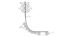
- FIG. 1 is a side view illustrating the state of implementation of a method for manufacturing a glass strip according to an embodiment of the present invention.
- the overflow downdraw method is adopted as a method for producing the strip glass, but other downdraw methods such as a slot downdraw method, a redraw method, or the like may be adopted.
- the manufacturing apparatus 1 used supports and transports a molded body 3 for molding the strip glass 2, a roller R1, a roller R2, a peripheral wall 4 surrounding the strip glass 2 and the molded body 3, and the strip glass 2.
- the rollers 5 and 6 and the conveyor 7 are the main components.
- the formed body 3 is formed while lowering the glass strip 2 from its lower end.
- a set of rollers R ⁇ b> 1 that contact the belt-like glass 2 from both sides is disposed below the molded body 3.
- the pair of rollers R ⁇ b> 1 abuts only at both ends in the width direction of the band-shaped glass 2 on any surface side of the band-shaped glass 2.
- the roller R1 has a function of regulating the shrinkage in the width direction while cooling the strip glass 2.
- roller R1 a plurality of sets (five sets in the present embodiment) of a pair of rollers R2 that contact the belt-like glass 2 from both sides are disposed along the vertical direction.
- the pair of rollers R ⁇ b> 2 abuts only on both ends in the width direction of the band-shaped glass 2 on any surface side of the band-shaped glass 2.
- the roller R2 has a function of extending the strip glass 2 downward.
- the peripheral wall 4 surrounds the roller R1, the roller R2, the strip glass 2, and the molded body 3.
- the peripheral wall 4 has an opening 8 at the lower end thereof, and the strip glass 2 goes out to the external space through the opening 8.
- the peripheral wall 4 has substantially no opening with respect to the external space other than the opening 8, and has, for example, a heat retaining function of the molded body 3 and a slow cooling function of the strip-shaped glass 2.
- the internal space of the peripheral wall 4 is partitioned into a first space S1 and a second space S2 by the molded body 3 and the strip glass 2 descending from the molded body 3.
- a temperature difference providing means for adjusting the temperature of each of the first space S1 and the second space S2 and providing a temperature difference between the spaces S1 and S2. Yes.
- a temperature difference is applied so that the temperature of the first space S1 is higher than that of the second space S2 during the production of the strip glass 2.
- this temperature difference application is used as a glass bending means for bending the belt-like glass 2.
- a plurality of sets (three sets in the present embodiment) of a set of rollers 5 that abut the belt-like glass 2 from both sides are disposed along the vertical direction. Further, the pair of rollers 5 abuts only at both ends in the width direction of the band-shaped glass 2 on any surface side of the band-shaped glass 2.
- a plurality of other types of rollers 6 are arranged in a substantially arc shape in a side view, and each abuts the lower surface of the belt-like glass 2. .
- Each of these rollers 6 may extend over the entire width direction of the band-shaped glass 2 or may be in a part (one place or a plurality of places) in the width direction.
- a conveyor 7 is arranged adjacent to the lateral direction of the roller 6 at the downstream end, and the lower surface of the strip-shaped glass 2 abuts on the upper surface of the conveyor 7.
- the conveyor 7 is configured such that its width is greater than the width of the strip glass 2.
- the transport direction of the strip glass 2 is set so that the front surface of the strip glass 2 is the top surface. Change direction horizontally.
- the band-shaped glass 2 is introduced into the direction changing region in a state where the surface side is curved so as to be concave in the width direction. This manufacturing method will be described in detail below.
- the glass strip 2 is formed while being sent vertically downward from the lower end of the molded body 3.
- the belt-like glass 2 is drawn downward by the roller R2 while being cooled by the roller R1 and being restricted in contraction in the width direction.
- part except the width direction both ends in the strip glass 2 will be 300 micrometers or less.
- the thickness of both end portions in the width direction of the band-shaped glass 2 is larger than the plate thickness of the above portion, and both end portions in the width direction in this state are called ear portions.
- the temperature difference is given to the spaces S1 and S2 of the peripheral wall 4 by the temperature difference giving means, and the temperature of the first space S1 is higher than that of the second space S2.
- the upward airflow is stronger in the first space S1 than in the second space S2, so that the glass strip 2 is curved so that the surface side is concave in the width direction.
- the glass strip 2 is transferred downward by the rotation of the roller 5 while maintaining this curved state.
- the glass strip 2 is changed from the downward direction to the horizontal direction by the rotation of the roller 6. That is, the above-mentioned direction change region is a region where the roller 6 is disposed, and the glass strip 2 is introduced into this region in a curved state.
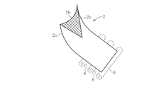
- reference numeral 2 a indicates an end in the width direction of the band-shaped glass 2
- reference numeral 2 b indicates a curved vertex of the band-shaped glass 2 (the same applies to the drawings described later).
- the strip glass 2 is transferred in the lateral direction (along the horizontal direction in the present embodiment) by the swiveling motion of the conveyor 7.
- the strip glass 2 is continuously manufactured.
- the curved state of the band-shaped glass 2 described above is the maximum separation distance (virtual line L) of the band-shaped glass 2 with respect to the virtual line L connecting both widthwise ends of the band-shaped glass 2 in the curved state, as shown in FIG. To the curved vertex 2b).
- the maximum separation distance ⁇ is positive on the surface side of the strip glass 2 (upper side in the figure).
- This maximum separation distance ⁇ satisfies the relationship 0> ⁇ ⁇ ⁇ 200 mm.
- This relationship is preferably 0> ⁇ ⁇ ⁇ 100 mm, more preferably 0> ⁇ ⁇ ⁇ 50 mm.
- the value of the maximum separation distance ⁇ can be adjusted by adjusting the temperature difference between the spaces S1 and S2 of the peripheral wall 4. In the present invention, the maximum separation distance ⁇ is measured below the lowermost roller R2.
- the glass strip 2 is introduced into the region of the roller 6 for direction change in a curved state so that the surface side is concave in the width direction. That is, when the glass strip 2 is introduced into the direction changing region, the glass strip is intentionally curved so that the surface side is concave in the width direction, so that it is in a stable state and has an appropriate degree of curvature. It is said that.
- the band-shaped glass 2 since the direction change is performed without undue stress acting on the band-shaped glass 2, the band-shaped glass 2 can be easily bent for the direction change. Therefore, breakage of the strip glass 2 can be suppressed.
- the glass strip 2 is curved so that the surface side thereof is convex in the width direction
- the following situation occurs.
- the curved state is maintained up to the region of the roller 6 for changing the direction.
- the glass bending means may utilize the generation of an electric field around the belt-like glass 2, may use the inclined molded body 3, and bends the lower end portion.
- the formed molded body 3 may be used, and further, wind pressure may be used.
- the position where the strip glass 2 is curved so that the surface side is concave may be during slow cooling (before solidification) or after solidification. However, after the production, in order to reduce the possibility that the adverse effects (warping, internal stress, etc.) of curving the band-shaped glass 2 remain, it is preferable that the glass is solidified.
- the bending direction of the strip glass 2 may be reversed at a plurality of locations in the manufacturing process. Even in such a case, the effect of the present invention can be enjoyed by controlling the maximum separation distance ⁇ among all the curved portions. Since this invention is for suppressing the glass breakage of the strip glass 2 in the region for changing the direction, the maximum separation distance in the vicinity of the opening 8 of the peripheral wall 4 that affects the strip glass 2 in that region. It is preferable to control ⁇ .
- the downdraw method used in the production method of the present invention is not particularly limited, it is possible to produce a strip glass having a good surface quality without performing polishing. Therefore, as in the above embodiment, the overflow downdraw method is used. It is preferable to adopt the method.
- the reason why a strip glass having a good surface quality can be produced is that the surface to be the surface of the strip glass does not come into contact with anything other than air and is molded in a free surface state.
- the overflow down-draw method is to draw molten glass from both sides of the bowl-shaped structure, which is a heat-resistant molded body, and to draw the overflowed molten glass together at the lower end of the bowl-shaped structure. And a method for producing a strip glass.
- the structure and material of the bowl-shaped structure are not particularly limited as long as the dimensions and surface accuracy of the band-shaped glass realize the quality required for the intended use. Further, the downward stretching may be performed by applying any force to the belt-like glass.
- a method may be adopted in which a heat-resistant roller having a sufficiently large width is rotated and stretched in contact with the belt-like glass, or a plurality of pairs of heat-resistant rollers are arranged in the width direction end face of the belt-like glass. You may employ
- the glass is easily cooled during drawing, in other words, the viscosity is likely to increase.
- the glass away from the molding equipment shrinks in the width direction due to the surface tension, The viscosity rises remarkably due to a rapid temperature drop.
- the viscosity of the glass immediately after being drawn from the molded body is 10 5.0 dPa ⁇ s or less, In particular, 10 4.8 dPa ⁇ s or less, 10 4.6 dPa ⁇ s or less, 10 4.4 dPa ⁇ s or less, 10 4.2 dPa ⁇ s or less, 10 4.0 dPa ⁇ s or less, It is preferable to control the temperature by taking measures such as heating and heat retention. Thus, by controlling the temperature, it is possible to widen the plate width without breaking even if a tensile stress is applied in the width direction of the strip glass. Further, it can be easily drawn downward.
- the viscosity of the glass is preferably 10 3.5 dPa ⁇ s or more, 10 3.7 dPa ⁇ s or more, 10 3.8 dPa ⁇ s or more, 10 3.9 dPa ⁇ s or more.
- the manufacturing method of the strip glass of the present invention includes a step of slowly cooling the strip glass. If the glass cooling rate is increased during the slow cooling, the heat shrinkage rate is increased, which is not preferable. On the other hand, when the cooling rate is too slow, productivity is deteriorated, or the slow cooling area in the production process becomes unduly long, which is not preferable.
- the viscosity of the glass is 10 10 to 10 14.5 dPa ⁇ s, particularly 10 11 to 10 14 dPa ⁇ s, more preferably 10 12 to 10 14 dPa ⁇ s.
- the average cooling rate is preferably 100 ° C./min or less, particularly 80 ° C./min or less, 50 ° C./min or less, 30 ° C./min or less, or 20 ° C./min or less.
- the average cooling rate is preferably 1 ° C./min or more, 2 ° C./min or more, 5 ° C./min or more, 10 ° C./min or more.
- the “average cooling rate” is obtained by dividing the temperature range corresponding to the viscosity range of the glass by the time required for the glass to pass.
- the moving direction of the strip glass may be changed from the lower side to the horizontal direction during the slow cooling.
- the strip glass By turning the strip glass during slow cooling, sufficient time and distance to achieve the desired thermal shrinkage can be used for slow cooling. That is, there is no restriction on the height, which is a particular problem when the downdraw method is adopted.
- various methods can be employed. For example, a method of changing the direction along a roller conveyor composed of a large number of rollers, or a method of changing the direction by guiding only both ends in the width direction of the belt-like glass with an air conveyor can be adopted. Further, the direction may be changed by bending the belt-like glass in a free state without guiding it with a roller or the like.
- the radius of curvature of the strip glass required for the direction change may be adjusted according to the plate thickness. That is, it is necessary to increase the radius of curvature as the plate thickness increases, and conversely, the radius of curvature can be decreased as the plate thickness decreases.
- the manufacturing method of the strip glass of the present invention includes a step of cutting the strip glass that has been slowly cooled into a predetermined length.
- the cutting referred to here is not limited to cutting to make the strip glass suitable for the end use, but includes cutting for stripping the strip glass accompanying roll replacement in the case of adopting a roll process described later.
- various methods such as a method in which a scribe line is put in advance with a cutter or laser light and then folded, and a method in which fusing with laser light is performed can be employed.
- the method for producing a glass strip of the present invention may further include a step of cutting the glass strip after making it into a roll form.
- a step of cutting the glass strip after making it into a roll form.
- the minimum radius of curvature at the time of winding is preferably 200 mm or less, particularly 150 mm or less, 100 mm or less, 70 mm or less, 50 mm or less, particularly 30 mm or less in the case of a strip glass having a plate thickness of 100 ⁇ m, for example.
- an end separation step of separating the width direction end portion (so-called ear portion) of the belt-like glass can be provided.
- laser cutting that cuts glass with thermal stress generated by laser beam irradiation and cooling, laser cutting that melts and cuts glass with the energy of laser light, and irradiation with short pulse laser light
- a method of continuously cutting and separating the edge of the glass such as a method of modifying and cutting, can be suitably employed.
- a carbon dioxide laser or a YAG laser or the like may be used as a laser to be used.
- Speed ratio (speed of crack progressed by laser ⁇ plate drawing speed) / (plate drawing speed) ⁇ 100 is ⁇ 10% or less, ⁇ 5% or less, ⁇ 1% or less, ⁇ 0.5% or less, ⁇ 0 It is preferably 1% or less.
- the surface of the glass is a fire-making surface, so that the surface quality is extremely high and a polishing step is not necessary. Furthermore, it is preferable to use it in an unpolished state because the mechanical strength of the glass is increased. That is, the theoretical strength of glass is inherently very high. However, even stresses far below the theoretical strength often lead to failure. The reason is that a small defect called Griffith flow occurs on the glass surface in a process after the glass molding, for example, a polishing process.
- the width of the strip glass obtained by the method for producing strip glass of the present invention is preferably 500 mm or more.
- the preferable plate width of the strip glass is 600 mm or more, 800 mm or more, 1000 mm or more, 1200 mm or more, 1500 mm or more, 2000 mm or more.
- belt-shaped glass can be adjusted with the magnitude
- the edge roller is a roller installed at the uppermost stage, and is a roller that controls the plate width by applying a tension in the width direction while cooling the band-shaped glass flowing down from the molded body.
- the thickness of the obtained strip-shaped glass is preferably 300 ⁇ m or less, particularly preferably 200 ⁇ m or less, 100 ⁇ m or less, or 50 ⁇ m or less.
- the thinner the strip glass the lighter the device.
- the stress value generated when the glass is bent is lowered, the radius of curvature required for the direction change of the strip glass can be reduced.
- the glass strip is wound into a roll.
- laser cutting is employed for cutting off the end portion, it is possible to reduce the required output. Alternatively, if the output is constant, cutting can be performed at a higher speed.
- the plate thickness is thinner than 1 ⁇ m, the mechanical strength of the glass cannot be maintained.
- the plate thickness is preferably 1 ⁇ m or more, 5 ⁇ m or more, 10 ⁇ m or more, 30 ⁇ m or more, 50 ⁇ m or more, or 60 ⁇ m or more.
- belt-shaped glass can be adjusted with the flow volume of glass, and a board
- the difference between the maximum thickness and the minimum thickness of the obtained strip-shaped glass is preferably 20 ⁇ m or less, particularly 10 ⁇ m or less, 5 ⁇ m or less, 2 ⁇ m or less, or 1 ⁇ m or less.
- belt-shaped glass can be adjusted with the temperature in a slow cooling furnace.
- the average surface roughness Ra of the obtained strip glass is 100 mm or less. In particular, it is desirable to be 50 mm or less, 10 mm or less, 8 mm or less, 4 mm or less, 3 mm or less, or 2 mm or less. When the average surface roughness Ra of the strip glass exceeds 100 mm, the display characteristics of the organic EL device may be deteriorated.
- Ra here measured Rmax on the contact surface side of strip
- AFM Nanoscope IIIa
- Ra when the glass is pulled out from the roll, the glass-interleaf paper and the glass-glass may be peeled off continuously and the glass surface may be charged. When such charging occurs, charging breakdown may occur in a later process, or fine particles in the atmosphere may be adsorbed on the surface of the belt-shaped glass, causing problems.
- the average surface roughness Ra when the atmospheric pressure plasma treatment is used can be adjusted by, for example, the concentration of the source gas (CF 4 or SF 4 ).
- the undulation of the obtained band-like glass is preferably 1 ⁇ m or less. In particular, it is desirable to be 0.08 ⁇ m or less, 0.05 ⁇ m or less, 0.03 ⁇ m or less, 0.02 ⁇ m or less, or 0.01 ⁇ m or less.
- the undulation of the strip glass can be adjusted by the height of the stirring stirrer, the rotational speed, the temperature of the molded body, and the like.
- the swell is a value of Wcc measured based on the standard of JIS B 0601-1982 using Surfcom 750A manufactured by Tokyo Seimitsu Co., Ltd.
- the obtained glass strip is heated at a rate of 10 ° C./min from room temperature, held at 500 ° C. for 1 hour, and has a thermal shrinkage rate of 200 ppm or less when the temperature is lowered to a room temperature at a rate of 10 ° C./min. It is preferable that they are 150 ppm or less, 100 ppm or less, 80 ppm or less, 60 ppm or less, 50 ppm or less, 45 ppm or less, 40 ppm or less, 30 ppm or less, 20 ppm or less, 10 ppm or less.
- the thermal shrinkage rate of the strip glass can be reduced by optimizing the slow cooling conditions (slow cooling rate, slow cooling time, slow cooling temperature region, etc.).
- the surface roughness Ra of the end face of the obtained band-like glass is preferably 100 mm or less, particularly 80 mm or less, 50 mm or less, 20 mm or less, 10 mm or less, 8 mm or less, 6 mm or less. If it exceeds 100%, the probability that the glass is broken from the end face is increased, which is not preferable.
- the surface roughness Ra of the end surface of the strip glass can be adjusted by the laser output and the cutting speed.
- the glass liquid phase temperature is 1200 ° C. or lower, 1150 ° C. or lower so that the glass does not devitrify during molding. It is preferably 1130 ° C. or less, 1110 ° C. or less, 1090 ° C. or less, particularly preferably 1070 ° C. or less, and the viscosity at the liquidus temperature is 10 5.0 dPa ⁇ s or more, 10 5.6 dPa ⁇ s or more, 10 5.8 It is preferably dPa ⁇ s or more, particularly 10 6.0 dPa ⁇ s or more.
- the glass constituting the strip glass has a Young's modulus of 65 GPa or more, 67 GPa or more, 68 GPa or more, 69 GPa or more, and optimally 70 GPa or more.
- the glass constituting the strip glass is desirably as low in density as possible in order to reduce the weight of the device. Specifically, it is 2.7 g / cm 3 or less, 2.6 g / cm 3 or less, and 2. It is desirably 5 g / cm 3 or less, particularly 2.4 g / cm 3 or less.
- the glass constituting the glass strip has a thermal expansion coefficient of 25 to 100 ⁇ 10 5 in a temperature range of 30 to 380 ° C. so as to match the thermal expansion coefficient of various films formed on the glass strip in the manufacture of the device. It is desirable that they are ⁇ 7 / ° C., 30 to 90 ⁇ 10 ⁇ 7 / ° C., 30 to 60 ⁇ 10 ⁇ 7 / ° C., 30 to 45 ⁇ 10 ⁇ 7 / ° C., and 30 to 40 ⁇ 10 ⁇ 7 / ° C.
- the glass constituting the strip glass preferably has a strain point which is an index of heat resistance of the glass of 600 ° C. or higher, particularly 630 ° C. or higher.
- the content of SiO 2 is 40 to 80%. When the content of SiO 2 increases, it becomes difficult to melt and mold the glass. Therefore, it is desirably 75% or less, preferably 64% or less, 62% or less, and particularly 61% or less. On the other hand, if the content of SiO 2 is reduced, with the vitrification becomes difficult to form a glass network structure becomes difficult, since acid resistance or increased incidence of cracks or deterioration, 50% or more, preferably It is desirable that it is 55% or more, particularly 57% or more.
- the content of Al 2 O 3 is 0 to 20%.
- the content of Al 2 O 3 is increased, devitrified crystals are likely to precipitate on the glass and the liquid phase viscosity is lowered. Therefore, it is 20% or less, preferably 18% or less, 17.5% or less, particularly 17 % Or less is desirable.
- the content of Al 2 O 3 decreases, the strain point of the glass decreases or the Young's modulus decreases. Therefore, it is 3% or more, preferably 5% or more, 8.5% or more, 10% or more. 12% or more, 13% or more, 13.5% or more, 14% or more, and particularly preferably 14.5% or more.
- the content of B 2 O 3 is 0 to 17%.
- the content of B 2 O 3 increases, the strain point decreases, the Young's modulus decreases, and the acid resistance deteriorates. Therefore, it is 17% or less, preferably 15% or less, 13% or less, 12% or less, It is desirable that it is 11% or less, particularly 10.4% or less.
- the content of B 2 O 3 is low, the high-temperature viscosity is increased and the meltability is deteriorated, the crack generation rate is increased, the liquidus temperature is increased, and the density is increased. % Or more, preferably 3% or more, 4% or more, 5% or more, 7% or more, 8.5% or more, 8.8% or more, particularly 9% or more.
- MgO The content of MgO is 0 to 10%.
- MgO is a component that improves the Young's modulus and strain point of the glass and lowers the high-temperature viscosity, and has the effect of reducing the crack generation rate. However, if it is contained in a large amount, the liquidus temperature rises, the devitrification resistance decreases, and the BHF resistance deteriorates. Therefore, it is 10% or less, 5% or less, 3% or less, 2% or less, 1.5 % Or less, 1% or less, or 0.5% or less is desirable.
- the CaO content is 0-15%.
- the content of CaO is increased, the density and the thermal expansion coefficient are increased. Therefore, it is desirably 15% or less, preferably 12% or less, 10% or less, 9% or less, or 8.5% or less.
- the CaO content is low, the meltability is deteriorated and the Young's modulus is low. Therefore, it is preferably 2% or more, 3% or more, 5% or more, 6% or more, 7% or more, particularly 7 It is desirable to contain 5% or more.
- the SrO content is 0-15%.
- the density and the thermal expansion coefficient are increased, so that it is 15% or less, preferably 12% or less, 10% or less, 6% or less, 5% or less, particularly 4.5% or less. desirable.
- the content of SrO is low, the meltability and chemical resistance are deteriorated. Therefore, preferably 0.5% or more, 1% or more, 2% or more, 3% or more, particularly 3.5% or more. Is desirable.
- the content of BaO is 0-30%.
- the content of BaO is increased, the density and the thermal expansion coefficient are increased. Therefore, 30% or less, preferably 25% or less, 20% or less, 15% or less, 10% or less, 5% or less, 2% or less, 1% In the following, it is particularly desirable that it be 0.5% or less.
- the liquidus temperature of the glass is remarkably lowered, and it is difficult to generate crystal foreign matters in the glass, thereby improving the meltability and formability of the glass. effective. Accordingly, if the total amount of these is small, the function as a flux is not sufficient, and the meltability is deteriorated. Therefore, the content is 5% or more, 8% or more, 9% or more, 11% or more, particularly 13% or more. desirable.
- the total amount of each component of MgO, CaO, SrO, BaO increases, the density increases, the weight of the glass cannot be reduced, and the crack generation rate tends to increase, so the total amount is 30% or less.
- the lower limit of the total amount is preferably 5% or more and 8% or more, and the upper limit is preferably 13% or less, 11% or less, and 10% or less.
- ZnO is a component that improves the meltability and increases the Young's modulus. However, if it is contained in a large amount, it tends to devitrify the glass, lower the strain point, and increase the density, which is not preferable. Accordingly, the content is preferably 15% or less, 10% or less, 5% or less, 3% or less, 1% or less, and particularly preferably 0.5% or less.
- ZrO 2 is a component that improves the Young's modulus, but if it exceeds 5%, the liquidus temperature rises, and zircon devitrified foreign matter tends to be generated, which is not preferable.
- a preferable range of the content of ZrO 2 is 3% or less, more preferably 1% or less, still more preferably 0.5% or less, and most preferably 0.1% or less.
- Y 2 O 3 , Nb 2 O 3 , and La 2 O 3 can be contained up to about 5% in the present invention. These components have a function of increasing the strain point, Young's modulus, etc., but if they are contained in a large amount, the density increases, which is not preferable.
- the glass contains 0 to 3% of one or more selected from the group of As 2 O 3 , Sb 2 O 3 , CeO 2 , SnO 2 , F, Cl, and SO 3 as a fining agent.
- As 2 O 3 , Sb 2 O 3 and F, especially As 2 O 3 and Sb 2 O 3 should be refrained from use as much as possible from an environmental point of view, and each content is less than 0.1%.
- preferred fining agents are SnO 2 , SO 3 and Cl.
- the SnO 2 content is preferably 0 to 1%, 0.01 to 0.5%, particularly preferably 0.05 to 0.4%.
- SnO 2 + Cl + SO 3 is 0.001 to 1%, 0.01 to 0.5%, and 0.01 to 0.3%.
- the glass of this example is an alkali-free glass, and its composition is mass percentage, SiO 2 is 60%, Al 2 O 3 is 16%, B 2 O 3 is 10%, MgO is 0.3%, CaO. Is 8%, SrO is 5%, BaO is 0.5%, and SnO 2 is 0.2%.
- This glass had a liquidus temperature of 1070 ° C., a Young's modulus of 73 GPa, a density of 2.45 g / cm 3 , a strain point of 650 ° C., and a thermal expansion coefficient of 38 ⁇ 10 ⁇ 7 / ° C. (30 to 380 ° C.). It was.
- “Non-alkali glass” refers to glass having an alkali metal oxide content of less than 1000 ppm in the glass composition.
- a strip glass having a plate width of 1600 mm and an average plate thickness of 100 ⁇ m was formed by stretching downward at about 600 cm / min by an overflow down draw method.
- the glass strip is curved by adjusting the temperature of the inner space of the surrounding wall, it is introduced into the region for changing the direction, and the direction of transport of the glass ribbon is changed from the downward direction to the horizontal direction, continuously.
- Table 1 shows the evaluation results in each curved state when the curved state (maximum separation distance ⁇ ) is changed by adjusting the temperature of the internal space of the surrounding wall.
- the meanings of the symbols in the evaluation of Table 1 are as follows. ⁇ : No glass breakage, small glass warpage ⁇ : No glass breakage ⁇ : No glass breakage, occurrence of shape with stress concentration part ⁇ : Glass breakage
Abstract
Priority Applications (4)
| Application Number | Priority Date | Filing Date | Title |
|---|---|---|---|
| EP12861340.3A EP2799404B1 (fr) | 2011-12-26 | 2012-12-17 | Procédé de fabrication de verre en forme de bande |
| US14/131,257 US9260336B2 (en) | 2011-12-26 | 2012-12-17 | Method for manufacturing band-shaped glass |
| CN201280029807.7A CN103608306B (zh) | 2011-12-26 | 2012-12-17 | 带状玻璃的制造方法 |
| KR1020137031695A KR101574589B1 (ko) | 2011-12-26 | 2012-12-17 | 띠형상 유리의 제조방법 |
Applications Claiming Priority (2)
| Application Number | Priority Date | Filing Date | Title |
|---|---|---|---|
| JP2011-283380 | 2011-12-26 | ||
| JP2011283380A JP5831212B2 (ja) | 2011-12-26 | 2011-12-26 | 帯状ガラスの製造方法 |
Publications (1)
| Publication Number | Publication Date |
|---|---|
| WO2013099676A1 true WO2013099676A1 (fr) | 2013-07-04 |
Family
ID=48697168
Family Applications (1)
| Application Number | Title | Priority Date | Filing Date |
|---|---|---|---|
| PCT/JP2012/082666 WO2013099676A1 (fr) | 2011-12-26 | 2012-12-17 | Procédé de fabrication de verre en forme de bande |
Country Status (7)
| Country | Link |
|---|---|
| US (1) | US9260336B2 (fr) |
| EP (1) | EP2799404B1 (fr) |
| JP (1) | JP5831212B2 (fr) |
| KR (1) | KR101574589B1 (fr) |
| CN (1) | CN103608306B (fr) |
| TW (1) | TW201328993A (fr) |
| WO (1) | WO2013099676A1 (fr) |
Cited By (6)
| Publication number | Priority date | Publication date | Assignee | Title |
|---|---|---|---|---|
| JP2016124758A (ja) * | 2015-01-05 | 2016-07-11 | 日本電気硝子株式会社 | 支持ガラス基板及びその製造方法 |
| JP2016124757A (ja) * | 2015-01-05 | 2016-07-11 | 日本電気硝子株式会社 | ガラス板及びその製造方法 |
| WO2018070258A1 (fr) * | 2016-10-11 | 2018-04-19 | 日本電気硝子株式会社 | Procédé et dispositif de production d'un film de verre en forme de bande |
| WO2018070207A1 (fr) * | 2016-10-11 | 2018-04-19 | 日本電気硝子株式会社 | Procédé de production d'un film de verre |
| JP2020172436A (ja) * | 2020-07-20 | 2020-10-22 | 日本電気硝子株式会社 | 支持ガラス基板及びそれを用いた積層体 |
| WO2021171903A1 (fr) * | 2020-02-25 | 2021-09-02 | 日本電気硝子株式会社 | Procédé de fabrication d'un film de verre |
Families Citing this family (13)
| Publication number | Priority date | Publication date | Assignee | Title |
|---|---|---|---|---|
| DE102011084128A1 (de) * | 2011-10-07 | 2013-04-11 | Schott Ag | Verfahren zum Schneiden eines Dünnglases mit spezieller Ausbildung der Kante |
| CN107848859B (zh) * | 2015-07-07 | 2020-12-25 | 康宁股份有限公司 | 在分离线处加热移动的玻璃带和/或从玻璃带中分离玻璃片的设备和方法 |
| DE102017101808A1 (de) | 2016-02-04 | 2017-08-10 | Schott Ag | Verfahren zur Dickenkontrolle eines Substrates |
| JP6315011B2 (ja) * | 2016-03-15 | 2018-04-25 | 旭硝子株式会社 | 無アルカリガラス基板、および無アルカリガラス基板の製造方法 |
| JP6702065B2 (ja) * | 2016-08-01 | 2020-05-27 | 日本電気硝子株式会社 | ガラス板の製造方法およびガラス板製造装置 |
| EP3589588A1 (fr) * | 2017-02-28 | 2020-01-08 | Corning Incorporated | Article en verre à variation d'épaisseur réduite, son procédé de fabrication et appareil associé |
| US10882775B2 (en) | 2017-08-10 | 2021-01-05 | AGC Inc. | Glass substrate |
| JP7033269B2 (ja) | 2017-12-11 | 2022-03-10 | 日本電気硝子株式会社 | 帯状ガラスの製造方法、及び帯状ガラスの製造装置 |
| WO2019151246A1 (fr) * | 2018-01-31 | 2019-08-08 | 日本電気硝子株式会社 | Rouleau de verre, procédé de fabrication de rouleau de verre et procédé d'évaluation de la qualité |
| JP7148837B2 (ja) * | 2018-06-22 | 2022-10-06 | 日本電気硝子株式会社 | ガラスロールの製造方法 |
| JPWO2020255625A1 (fr) * | 2019-06-18 | 2020-12-24 | ||
| DE102019129036A1 (de) * | 2019-10-28 | 2021-04-29 | Schott Ag | Verfahren zur Herstellung von Glasscheiben und verfahrensgemäß hergestellte Glasscheibe sowie deren Verwendung |
| CN115180824B (zh) * | 2022-07-05 | 2024-01-16 | 河北光兴半导体技术有限公司 | 防火玻璃组合物、防火玻璃及其制备方法 |
Citations (3)
| Publication number | Priority date | Publication date | Assignee | Title |
|---|---|---|---|---|
| JP2000335928A (ja) | 1999-04-27 | 2000-12-05 | Carl Zeiss:Fa | 個別のガラス板を製造する方法及び装置 |
| WO2011102175A1 (fr) * | 2010-02-18 | 2011-08-25 | 日本電気硝子株式会社 | Procédé de fabrication pour film de verre et dispositif de fabrication pour celui-ci |
| WO2012011439A1 (fr) * | 2010-07-23 | 2012-01-26 | 日本電気硝子株式会社 | Dispositif de production d'un film de verre et son procédé de production |
Family Cites Families (10)
| Publication number | Priority date | Publication date | Assignee | Title |
|---|---|---|---|---|
| US3522029A (en) * | 1966-12-22 | 1970-07-28 | Libbey Owens Ford Co | Method of reshaping glass sheets by differential cooling |
| WO2003014032A1 (fr) | 2001-08-08 | 2003-02-20 | Richard Pitbladdo | Appareil de formage de feuilles de verre |
| JP4776859B2 (ja) * | 2002-06-24 | 2011-09-21 | 旭硝子株式会社 | ガラス板の位置合せ方法及びその装置並びにガラス板の曲げ成形方法 |
| EP1721872A1 (fr) * | 2005-05-10 | 2006-11-15 | Corning Incorporated | Procédé de fabrication d'une feuille de verre |
| US7818980B2 (en) * | 2006-11-30 | 2010-10-26 | Corning Incorporated | Forming glass sheets with improved shape stability |
| US8899078B2 (en) * | 2008-11-26 | 2014-12-02 | Corning Incorporated | Glass sheet stabilizing system, glass manufacturing system and method for making a glass sheet |
| US20110094267A1 (en) * | 2009-10-28 | 2011-04-28 | Kenneth William Aniolek | Methods of producing glass sheets |
| JP2011190132A (ja) * | 2010-03-12 | 2011-09-29 | Nippon Electric Glass Co Ltd | ガラスロール及びその製造方法 |
| JP5696393B2 (ja) | 2010-08-02 | 2015-04-08 | 日本電気硝子株式会社 | ガラスフィルムの割断方法 |
| US8925352B2 (en) * | 2011-02-04 | 2015-01-06 | Pilkington Group Limited | Method of shaping glass sheets |
-
2011
- 2011-12-26 JP JP2011283380A patent/JP5831212B2/ja active Active
-
2012
- 2012-12-17 KR KR1020137031695A patent/KR101574589B1/ko active IP Right Grant
- 2012-12-17 EP EP12861340.3A patent/EP2799404B1/fr active Active
- 2012-12-17 US US14/131,257 patent/US9260336B2/en active Active
- 2012-12-17 WO PCT/JP2012/082666 patent/WO2013099676A1/fr active Application Filing
- 2012-12-17 CN CN201280029807.7A patent/CN103608306B/zh active Active
- 2012-12-25 TW TW101149871A patent/TW201328993A/zh unknown
Patent Citations (3)
| Publication number | Priority date | Publication date | Assignee | Title |
|---|---|---|---|---|
| JP2000335928A (ja) | 1999-04-27 | 2000-12-05 | Carl Zeiss:Fa | 個別のガラス板を製造する方法及び装置 |
| WO2011102175A1 (fr) * | 2010-02-18 | 2011-08-25 | 日本電気硝子株式会社 | Procédé de fabrication pour film de verre et dispositif de fabrication pour celui-ci |
| WO2012011439A1 (fr) * | 2010-07-23 | 2012-01-26 | 日本電気硝子株式会社 | Dispositif de production d'un film de verre et son procédé de production |
Non-Patent Citations (1)
| Title |
|---|
| See also references of EP2799404A4 * |
Cited By (23)
| Publication number | Priority date | Publication date | Assignee | Title |
|---|---|---|---|---|
| KR102430749B1 (ko) * | 2015-01-05 | 2022-08-09 | 니폰 덴키 가라스 가부시키가이샤 | 유리판 및 그 제조 방법 |
| JP2016124757A (ja) * | 2015-01-05 | 2016-07-11 | 日本電気硝子株式会社 | ガラス板及びその製造方法 |
| WO2016111158A1 (fr) * | 2015-01-05 | 2016-07-14 | 日本電気硝子株式会社 | Plaque en verre et son procédé de fabrication |
| WO2016111152A1 (fr) * | 2015-01-05 | 2016-07-14 | 日本電気硝子株式会社 | Substrat de soutien en verre et son procédé de fabrication |
| KR20170103739A (ko) * | 2015-01-05 | 2017-09-13 | 니폰 덴키 가라스 가부시키가이샤 | 유리판 및 그 제조 방법 |
| KR102561430B1 (ko) | 2015-01-05 | 2023-07-31 | 니폰 덴키 가라스 가부시키가이샤 | 지지 유리 기판 및 적층체 |
| KR102509784B1 (ko) * | 2015-01-05 | 2023-03-14 | 니폰 덴키 가라스 가부시키가이샤 | 유리판 및 적층체 |
| KR20220116564A (ko) * | 2015-01-05 | 2022-08-23 | 니폰 덴키 가라스 가부시키가이샤 | 지지 유리 기판 및 그 제조 방법 |
| KR20220113546A (ko) * | 2015-01-05 | 2022-08-12 | 니폰 덴키 가라스 가부시키가이샤 | 유리판 및 그 제조 방법 |
| US10737965B2 (en) | 2015-01-05 | 2020-08-11 | Nippon Electric Glass Co., Ltd. | Method of manufacturing glass sheet |
| JP2016124758A (ja) * | 2015-01-05 | 2016-07-11 | 日本電気硝子株式会社 | 支持ガラス基板及びその製造方法 |
| WO2018070258A1 (fr) * | 2016-10-11 | 2018-04-19 | 日本電気硝子株式会社 | Procédé et dispositif de production d'un film de verre en forme de bande |
| KR102267240B1 (ko) | 2016-10-11 | 2021-06-21 | 니폰 덴키 가라스 가부시키가이샤 | 띠형상 유리 필름의 제조 방법 및 제조 장치 |
| TWI735671B (zh) * | 2016-10-11 | 2021-08-11 | 日商日本電氣硝子股份有限公司 | 玻璃薄膜的製造方法 |
| TWI722249B (zh) * | 2016-10-11 | 2021-03-21 | 日商日本電氣硝子股份有限公司 | 帶狀玻璃膜的製造方法及製造裝置 |
| KR20190067739A (ko) * | 2016-10-11 | 2019-06-17 | 니폰 덴키 가라스 가부시키가이샤 | 띠형상 유리 필름의 제조 방법 및 제조 장치 |
| JP2018062430A (ja) * | 2016-10-11 | 2018-04-19 | 日本電気硝子株式会社 | ガラスフィルムの製造方法 |
| WO2018070207A1 (fr) * | 2016-10-11 | 2018-04-19 | 日本電気硝子株式会社 | Procédé de production d'un film de verre |
| US11787724B2 (en) | 2016-10-11 | 2023-10-17 | Nippon Electric Glass Co., Ltd. | Method for producing glass film |
| WO2021171903A1 (fr) * | 2020-02-25 | 2021-09-02 | 日本電気硝子株式会社 | Procédé de fabrication d'un film de verre |
| JP7450851B2 (ja) | 2020-02-25 | 2024-03-18 | 日本電気硝子株式会社 | ガラスフィルムの製造方法 |
| JP2020172436A (ja) * | 2020-07-20 | 2020-10-22 | 日本電気硝子株式会社 | 支持ガラス基板及びそれを用いた積層体 |
| JP7051053B2 (ja) | 2020-07-20 | 2022-04-11 | 日本電気硝子株式会社 | 支持ガラス基板及びそれを用いた積層体 |
Also Published As
| Publication number | Publication date |
|---|---|
| EP2799404A1 (fr) | 2014-11-05 |
| CN103608306A (zh) | 2014-02-26 |
| EP2799404B1 (fr) | 2019-05-29 |
| TW201328993A (zh) | 2013-07-16 |
| JP2013133246A (ja) | 2013-07-08 |
| KR101574589B1 (ko) | 2015-12-04 |
| TWI560155B (fr) | 2016-12-01 |
| CN103608306B (zh) | 2015-11-25 |
| KR20140015517A (ko) | 2014-02-06 |
| US20140137602A1 (en) | 2014-05-22 |
| US9260336B2 (en) | 2016-02-16 |
| EP2799404A4 (fr) | 2015-08-26 |
| JP5831212B2 (ja) | 2015-12-09 |
Similar Documents
| Publication | Publication Date | Title |
|---|---|---|
| JP5831212B2 (ja) | 帯状ガラスの製造方法 | |
| JP5582446B2 (ja) | フィルム状ガラスの製造方法及び製造装置 | |
| KR101736262B1 (ko) | 유리 필름의 제조방법 및 그 제조장치 | |
| US9586854B2 (en) | Alkali-free glass | |
| JP5794325B2 (ja) | 電子デバイス用ガラス基板の製造方法、及び、電子デバイス用カバーガラスの製造方法 | |
| US8322160B2 (en) | Process and apparatus for producing glass sheet | |
| JP5281634B2 (ja) | ガラス板およびガラス板の製造方法 | |
| TWI619686B (zh) | 玻璃及玻璃基板 | |
| JP5428287B2 (ja) | ガラス板の製造方法及び製造設備 | |
| TWI576295B (zh) | 玻璃卷的製造方法與玻璃卷 | |
| JP2012111661A (ja) | ガラス基板およびその製造方法 | |
| JP5403487B2 (ja) | ガラスロール | |
| US9656901B2 (en) | Method of manufacturing a glass roll | |
| JP2012087004A (ja) | 帯状ガラスフィルム製造方法及び帯状ガラスフィルム製造装置 | |
| WO2009081740A1 (fr) | Procédé et appareil de fabrication d'une plaque de verre | |
| WO2007111054A1 (fr) | Panneau d'affichage | |
| WO2013042379A1 (fr) | Procédé et dispositif de fabrication de feuille de verre | |
| WO2014112415A1 (fr) | Procédé de fabrication d'un substrat de verre présentant un film laminé | |
| JP2010215436A (ja) | ガラスフィルム積層体 | |
| JP6225652B2 (ja) | ガラス基板製造方法、及びガラス基板製造装置 | |
| JP2019085306A (ja) | ガラス物品の製造方法及びその製造装置 | |
| WO2014178405A1 (fr) | Stratifié de film de verre, et procédé de production de dispositif électronique | |
| JP2016060135A (ja) | ガラスフィルム積層体、及び、電子デバイスの製造方法 |
Legal Events
| Date | Code | Title | Description |
|---|---|---|---|
| 121 | Ep: the epo has been informed by wipo that ep was designated in this application |
Ref document number: 12861340 Country of ref document: EP Kind code of ref document: A1 |
|
| ENP | Entry into the national phase |
Ref document number: 20137031695 Country of ref document: KR Kind code of ref document: A |
|
| WWE | Wipo information: entry into national phase |
Ref document number: 14131257 Country of ref document: US |
|
| WWE | Wipo information: entry into national phase |
Ref document number: 2012861340 Country of ref document: EP |
|
| NENP | Non-entry into the national phase |
Ref country code: DE |