WO2013099446A1 - プレフィルドシリンジ用外筒の製造方法 - Google Patents
プレフィルドシリンジ用外筒の製造方法 Download PDFInfo
- Publication number
- WO2013099446A1 WO2013099446A1 PCT/JP2012/078884 JP2012078884W WO2013099446A1 WO 2013099446 A1 WO2013099446 A1 WO 2013099446A1 JP 2012078884 W JP2012078884 W JP 2012078884W WO 2013099446 A1 WO2013099446 A1 WO 2013099446A1
- Authority
- WO
- WIPO (PCT)
- Prior art keywords
- outer cylinder
- prefilled syringe
- group
- cyclic olefin
- prefilled
- Prior art date
- Legal status (The legal status is an assumption and is not a legal conclusion. Google has not performed a legal analysis and makes no representation as to the accuracy of the status listed.)
- Ceased
Links
Images
Classifications
-
- A—HUMAN NECESSITIES
- A61—MEDICAL OR VETERINARY SCIENCE; HYGIENE
- A61L—METHODS OR APPARATUS FOR STERILISING MATERIALS OR OBJECTS IN GENERAL; DISINFECTION, STERILISATION OR DEODORISATION OF AIR; CHEMICAL ASPECTS OF BANDAGES, DRESSINGS, ABSORBENT PADS OR SURGICAL ARTICLES; MATERIALS FOR BANDAGES, DRESSINGS, ABSORBENT PADS OR SURGICAL ARTICLES
- A61L31/00—Materials for other surgical articles, e.g. stents, stent-grafts, shunts, surgical drapes, guide wires, materials for adhesion prevention, occluding devices, surgical gloves, tissue fixation devices
- A61L31/08—Materials for coatings
- A61L31/082—Inorganic materials
-
- A—HUMAN NECESSITIES
- A61—MEDICAL OR VETERINARY SCIENCE; HYGIENE
- A61L—METHODS OR APPARATUS FOR STERILISING MATERIALS OR OBJECTS IN GENERAL; DISINFECTION, STERILISATION OR DEODORISATION OF AIR; CHEMICAL ASPECTS OF BANDAGES, DRESSINGS, ABSORBENT PADS OR SURGICAL ARTICLES; MATERIALS FOR BANDAGES, DRESSINGS, ABSORBENT PADS OR SURGICAL ARTICLES
- A61L31/00—Materials for other surgical articles, e.g. stents, stent-grafts, shunts, surgical drapes, guide wires, materials for adhesion prevention, occluding devices, surgical gloves, tissue fixation devices
- A61L31/04—Macromolecular materials
- A61L31/048—Macromolecular materials obtained by reactions only involving carbon-to-carbon unsaturated bonds
-
- A—HUMAN NECESSITIES
- A61—MEDICAL OR VETERINARY SCIENCE; HYGIENE
- A61M—DEVICES FOR INTRODUCING MEDIA INTO, OR ONTO, THE BODY; DEVICES FOR TRANSDUCING BODY MEDIA OR FOR TAKING MEDIA FROM THE BODY; DEVICES FOR PRODUCING OR ENDING SLEEP OR STUPOR
- A61M5/00—Devices for bringing media into the body in a subcutaneous, intra-vascular or intramuscular way; Accessories therefor, e.g. filling or cleaning devices, arm-rests
- A61M5/178—Syringes
- A61M5/31—Details
- A61M5/3129—Syringe barrels
Definitions
- the present invention relates to a prefilled syringe outer cylinder manufactured using a cyclic olefin resin.
- the material constituting the prefilled syringe is preferably a resin from the viewpoint of ease of handling such as light weight and difficulty in cracking.
- the prefilled syringe manufactured using polypropylene used for manufacturing a general syringe has a low water vapor barrier property of polypropylene, there is a problem that moisture contained in the drug volatilizes during storage.
- the resin that can be used as a raw material for the prefilled syringe is limited, and examples of the resin that can be used include an aromatic vinyl polymer as described in Patent Document 1.
- the cyclic olefin resin is known as a resin excellent in heat resistance, chemical resistance, water vapor barrier property and the like. Furthermore, since cyclic olefin resin is excellent also in transparency, when a prefilled syringe is manufactured using cyclic olefin resin, the effect that it will be easy to visually recognize a chemical
- medical agent will also be acquired.
- the present inventors tried to manufacture a prefilled syringe outer cylinder made of a cyclic olefin resin as a raw material, and the transparency of the manufactured prefilled syringe outer cylinder was It was not good.
- the present invention has been made to solve the above-described problems, and an object of the present invention is to provide a technique for manufacturing a prefilled syringe outer cylinder that is manufactured using a cyclic olefin resin as a raw material and has high transparency.
- the present inventors have made extensive studies to produce a prefilled syringe outer cylinder that is manufactured using a cyclic olefin resin as a raw material and has high transparency.
- the present invention provides the following.
- a lubricious hard film containing at least one element selected from Ti, Cr, Zr, C, Al and Ni is formed on the core surface.
- the lubricating hard coating is composed of at least one selected from diamond-like carbon (DLC), CrN, TiN, TiC, TiCN, TiAlN, TiCrN, AlCrN, ZrN, or Ni. Manufacturing method for prefilled syringe outer cylinder.
- DLC diamond-like carbon
- a prefilled syringe outer cylinder having high transparency can be produced using a cyclic olefin resin as a raw material.
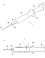
- FIG. 1 is a diagram schematically showing a prefilled syringe, in which (a) is a perspective view and (b) is an MM cross-sectional view of (a).
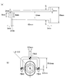
- Fig.2 (a) is a figure which shows the dimension of the outer cylinder for prefilled syringes manufactured in the Example, (b) is a figure which shows the position of the sprue, runner, and gate in a metal mold
- the present invention is a method for producing a prefilled syringe outer cylinder.
- the shape of the prefilled syringe outer cylinder manufactured in the present invention is not particularly limited.
- a general prefilled syringe in which the prefilled syringe outer cylinder of the present invention is used will be briefly described with reference to the drawings.
- FIG. 1A and 1B are diagrams schematically showing a prefilled syringe, FIG. 1A is a perspective view, and FIG. 1B is an MM cross-sectional view of FIG.
- the prefilled syringe 1 is inserted into the prefilled syringe outer cylinder 10 from the other end of the prefilled syringe outer cylinder 10, the cannula 20 connected to one end of the prefilled syringe outer cylinder 10, and the other end of the prefilled syringe outer cylinder 10. And a plunger 30.
- a luer 101 for connecting to the cannula 20 is formed at one end of the prefilled syringe outer cylinder 10, and a flange 102 is formed at the other end.
- the space inside the outer cylinder 10 for prefilled syringes is a medicine storage space in which a medicine is stored.
- the plunger 30 is inserted from the opening of the prefilled syringe outer cylinder 10 on the flange 102 side.
- the draft of the inner wall surface of the prefilled syringe outer cylinder 10 was set to (theta).
- the cannula 20 has a stopper 201 at the end, and the cannula 20 and the prefilled syringe outer cylinder 10 are connected to each other by fitting the stopper 201 with the lure 101.
- the plunger 30 is inserted from the end of the prefilled syringe outer cylinder 10 so as to be able to advance and retreat into the medicine accommodating space.
- the end of the plunger 30 is in contact with the medicine in the medicine housing space.
- a method for manufacturing a prefilled syringe outer cylinder will be briefly described. After storing the prefilled syringe 1 in a state filled with a medicine for a certain period of time, the plunger 30 is further pushed into the prefilled syringe outer cylinder 10 at the time of use, so that the volume of the medicine storage space is reduced and the lure is reduced. The drug is extruded from the portion 101, and the extruded drug passes through the cannula 20 and comes out of the prefilled syringe.
- the prefilled syringe 1 is stored for a certain period in a state where the medicine is accommodated therein. For this reason, when the outer cylinder 10 for prefilled syringes is comprised from the material with low water vapor permeability, the problem that the water
- the prefilled syringe outer cylinder 10 obtained by the production method of the present invention is composed of a cyclic olefin resin composition described later. Since the cyclic olefin resin composition exhibits the excellent chemical resistance and water vapor barrier properties of the cyclic olefin resin, when the prefilled syringe outer cylinder is manufactured using the cyclic olefin resin composition, the above problems are Does not occur.
- the prefilled syringe outer cylinder is manufactured using the cyclic olefin resin composition as a raw material, it is difficult to take out the prefilled syringe outer cylinder from the mold at the time of manufacture due to the inherent hardness of the cyclic olefin resin.
- the problem that it is difficult to take out the prefilled syringe outer cylinder from the mold at the time of manufacturing leads to a decrease in productivity.
- the prefilled syringe outer cylinder is manufactured by the following method, the transparency of the prefilled syringe outer cylinder manufactured using the cyclic olefin resin can be enhanced.
- the prefilled syringe outer cylinder can be easily taken out of the mold at the time of manufacture, and the productivity of the high quality prefilled syringe outer cylinder can be increased.
- the manufacturing method of the outer cylinder for prefilled syringes of this invention is a manufacturing method of the outer cylinder for prefilled syringes formed by injection-molding a cyclic olefin resin composition.
- a mold having a core surface roughness Rz of 50 ⁇ m or less is used as an injection mold.
- the method for adjusting the surface roughness Rz of the core to the above range is not particularly limited, and examples thereof include a method of polishing the core using an abrasive having a particle size of 2000 to 10,000.
- the surface roughness Rz decreases as the particle size count of the abrasive increases, and the surface roughness Rz increases as the particle size count decreases.
- the said surface roughness Rz can be adjusted by adjusting the particle size count of an abrasives suitably.
- the specific method for polishing is not particularly limited. For example, a method using a coarse abrasive such as sandpaper, or an abrasive called a buff made of liquid abrasive (compound) and cloth or sponge. Or a method using a combination of these methods.
- the surface roughness Rz decreases, and it becomes difficult to take out the prefilled syringe outer cylinder immediately after manufacture from the mold. For example, this problem starts to appear when the surface roughness Rz of the core is about 10 ⁇ m or less. Therefore, it is necessary to adjust the surface roughness of the core in consideration of the ease of taking out the prefilled syringe outer cylinder from the mold immediately after manufacture. For example, if the surface roughness Rz of the core is 20 ⁇ m or more and 50 ⁇ m or less, the prefilled syringe outer cylinder is excellent in transparency, and the problem that the prefilled syringe outer cylinder is difficult to take out from the mold does not occur at the time of manufacture.
- an abrasive having a particle size count of 2000 to 8000 it is preferable to use an abrasive having a particle size count of 2000 to 8000.
- a particularly preferable surface roughness Rz of the core is 30 ⁇ m or more and 50 ⁇ m or less.
- the transparency of the prefilled syringe outer cylinder can be improved by forming a hard lubricating film on the core.
- the lubricious hard coating contains at least one element selected from Ti, Cr, Zr, C, Al, and Si.
- the lubricious hard coating is preferably composed of at least one selected from diamond-like carbon (DLC), CrN, TiN, TiC, TiCN, TiAlN, TiCrN, AlCrN, ZrN, or Ni.
- the method for forming the lubricious hard film on the core is not particularly limited, but for example, it is formed by a deposition method.
- a vapor phase method is preferable.
- a CVD method such as a plasma CVD (Chemical Vapor Deposition) method using a DC power source, an AC power source or a high frequency power source as a power source, an AIP (Arc Ion Platting) method, or the like.
- Examples thereof include a PVD (Physical Vapor Deposition) method, a magnetron sputtering method, a sputtering method such as an ion beam sputtering method, and an ionization vapor deposition method.
- wet methods such as electrolytic plating and electroless plating, are mentioned.
- These lubricious hard coatings may be a single layer or multiple layers.
- the surface roughness Rz of the surface of the lubricious hard film may not be 50 ⁇ m or less. Since the friction coefficient of the surface of the lubricious hard coating is smaller than that of the core, the transparency of the prefilled syringe outer cylinder is high even if the surface roughness Rz is not 50 ⁇ m or less. However, the surface roughness of the mold surface on which the lubricious hard film is formed needs to be 50 ⁇ m or less because the surface roughness of the inner surface of the outer cylinder is reduced.
- ⁇ Cyclic olefin resin composition The cyclic olefin resin composition used as the raw material of the prefilled syringe outer cylinder will be described.
- the cyclic olefin resin composition contains a cyclic olefin resin.
- the cyclic olefin resin is not particularly limited as long as it contains a cyclic olefin component as a copolymerization component and is a polyolefin resin containing a cyclic olefin component in the main chain.
- examples thereof include addition polymers of cyclic olefins or hydrogenated products thereof, addition copolymers of cyclic olefins and ⁇ -olefins or hydrogenated products thereof.
- the cyclic olefin resin includes those obtained by grafting and / or copolymerizing the above polymer with an unsaturated compound having a polar group.
- Examples of the polar group include a carboxyl group, an acid anhydride group, an epoxy group, an amino group, an amide group, an ester group, a hydroxyl group, a sulfo group, a phosphono group, and a phosphino group.
- saturated compound examples include (meth) acrylic acid, maleic acid, maleic anhydride, itaconic anhydride, glycidyl (meth) acrylate, alkyl (meth) acrylate (carbon number 1 to 10) ester, alkyl maleate (carbon number 1 To 10) ester, (meth) acrylamide, (meth) acrylic acid-2-hydroxyethyl, etc., preferably carboxyl group, acid anhydride group, epoxy group, amino group, amide group, ester group, A hydroxyl group, a sulfo group, a phosphono group, and a phosphino group are mentioned.
- cyclic olefin resin an addition copolymer of a cyclic olefin and an ⁇ -olefin or a hydrogenated product thereof is preferable.
- cyclic olefin-based resin containing a cyclic olefin component as a copolymerization component a commercially available resin can be used.
- commercially available cyclic olefin-based resins include TOPAS (registered trademark) (Topas Advanced Polymers), Apel (registered trademark) (Mitsui Chemicals), Zeonex (registered trademark) (manufactured by Nippon Zeon), Examples include ZEONOR (registered trademark) (manufactured by ZEON Corporation), ARTON (registered trademark) (manufactured by JSR Corporation), and the like.
- Particularly preferable examples of the addition copolymer of cyclic olefin and ⁇ -olefin include: [1] an ⁇ -olefin component having 2 to 20 carbon atoms; and [2] a cyclic olefin component represented by the following general formula (I): Can be mentioned.
- R 1 to R 12 may be the same or different and are each selected from the group consisting of a hydrogen atom, a halogen atom, and a hydrocarbon group; R 9 and R 10 , R 11 and R 12 may be integrated to form a divalent hydrocarbon group, R 9 or R 10 and R 11 or R 12 may form a ring with each other.
- N represents 0 or a positive integer; When n is 2 or more, R 5 to R 8 may be the same or different in each repeating unit.
- the ⁇ -olefin component having 2 to 20 carbon atoms will be described.
- the ⁇ -olefin having 2 to 20 carbon atoms is not particularly limited.
- these ⁇ -olefin components may be used alone or in combination of two or more. Of these, ethylene is most preferably used alone.
- R 1 to R 12 in the general formula (I) may be the same or different and are selected from the group consisting of a hydrogen atom, a halogen atom, and a hydrocarbon group.
- R 1 to R 8 include, for example, a hydrogen atom; a halogen atom such as fluorine, chlorine and bromine; a lower alkyl group such as a methyl group, an ethyl group, a propyl group and a butyl group. May be different from each other, may be partially different, or all may be the same.
- R 9 to R 12 include, for example, hydrogen atom; halogen atom such as fluorine, chlorine, bromine; methyl group, ethyl group, propyl group, isopropyl group, butyl group, isobutyl group, hexyl group, stearyl.
- Alkyl group such as cyclohexyl group; cycloalkyl group such as cyclohexyl group; substituted or unsubstituted aromatic hydrocarbon group such as phenyl group, tolyl group, ethylphenyl group, isopropylphenyl group, naphthyl group, anthryl group; benzyl group, phenethyl And an aralkyl group in which an aryl group is substituted with an alkyl group, and the like. These may be different from each other, may be partially different, or all may be the same.
- R 9 and R 10 or R 11 and R 12 are integrated to form a divalent hydrocarbon group
- alkylidene groups such as an ethylidene group, a propylidene group, and an isopropylidene group. Can be mentioned.
- the formed ring may be monocyclic or polycyclic, or may be a polycyclic ring having a bridge.
- a ring having a double bond, or a ring composed of a combination of these rings may be used.
- these rings may have a substituent such as a methyl group.
- cyclic olefin component represented by the general formula (I) include those similar to those described in JP-A-2007-302722.
- cyclic olefin components may be used singly or in combination of two or more.
- a method for polymerizing an ⁇ -olefin component having 2 to 20 carbon atoms and a [2] cyclic olefin component represented by formula (I) and a method for hydrogenating the obtained polymer are particularly limited. Instead, it can be carried out according to known methods. Random copolymerization or block copolymerization may be used, but random copolymerization is preferred.
- the polymerization catalyst used is not particularly limited, and a cyclic olefin resin can be obtained by a known method using a conventionally known catalyst such as a Ziegler-Natta, metathesis, or metallocene catalyst.
- the cyclic olefin-based resin (A) does not impair the object of the present invention other than [1] the ⁇ -olefin component having 2 to 20 carbon atoms and [2] the cyclic olefin component represented by the general formula (I). In the range, other copolymerizable unsaturated monomer components may be contained as required.
- the unsaturated monomer that may be optionally copolymerized is not particularly limited, and examples thereof include hydrocarbon monomers containing two or more carbon-carbon double bonds in one molecule. Can be mentioned. Specific examples of the hydrocarbon monomer having two or more carbon-carbon double bonds in one molecule include those similar to those described in JP-A-2007-302722.
- the prefilled syringe outer cylinder becomes hard. Therefore, even if the draft angle ( ⁇ in FIG. 1B) of the inner wall surface of the prefilled syringe outer cylinder is small, if the draft angle is not substantially zero, the plunger is pushed during use to prefill the prefilled syringe. This hinders the extruding of the medicine in the syringe outer cylinder.
- the draft angle of the said inner wall surface is 0 degree
- the draft angle of the inner wall of the prefilled syringe outer cylinder is substantially zero in order to make it easy to remove the prefilled syringe outer cylinder from the mold.
- the prefilled syringe outer cylinder immediately after manufacture can be easily taken out from the mold even when the draft is substantially zero.
- the draft is substantially zero indicates that the draft is 0.5 degrees or less. And when the draft is 0.5 degrees or less, the problem of the above-mentioned difficulty arises.
- the cyclic olefin resin composition may contain components other than the cyclic olefin resin as long as the effects of the present invention are not impaired.
- components include other resins, inorganic fillers, nucleating agents, pigments, antioxidants, stabilizers, plasticizers, lubricants, mold release agents, and the like.
- the prefilled syringe outer cylinder of the present invention is manufactured by an injection molding method.
- the production conditions for injection molding are not particularly limited, and are appropriately set according to the cyclic olefin resin composition to be used.
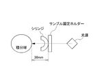
- the prefilled syringe manufactured by the manufacturing method of the present invention has high transparency. Specifically, the light transmittance when light having a wavelength of 450 nm incident perpendicularly to the side wall of the prefilled syringe outer cylinder passes through the side wall is 70% or more.
- the length L of the prefilled syringe outer cylinder is usually 30 mm or more and 150 mm or less, and the inner diameter R of the prefilled syringe outer cylinder is usually 2 mm or more and 50 mm or less. If it is an outer cylinder for prefilled syringes of the normal size as described above, the outer cylinder for prefilled syringes immediately after manufacture is set by setting the unevenness of the core of the injection mold to 30 ⁇ m or more and 50 ⁇ m or less as described above. Is less likely to come out of the mold.
- FIG. 1 a prefilled syringe outer cylinder having the shape shown in FIG. 1 is manufactured.
- the dimensions of the prefilled syringe outer cylinder are shown in FIG.
- the draft of an inner wall surface is 0 degree
- a mold having a cavity in the shape of the outer cylinder for a prefilled syringe includes a sprue, a runner, and a gate having a shape as shown in FIG.
- the gate position G is also shown in FIG.
- the sprue diameter, runner length, and gate diameter are 4.0 mm, 20 mm, and 3.0 mm, respectively.
- three ejector pins are provided at the connection point between the sprue and the runner and the connection point between the runner and the gate (PIN1 to PIN3).
- the ejector pin represented by PIN1 is connected to a pressure sensor (“9223A”, manufactured by Nippon Kistler) for measuring the mold release resistance. Data obtained from this pressure sensor is converted using an industrial charge amplifier (“5073A”, manufactured by Nippon Kistler), and the converted data can be monitored by DATAFLOW Light II (manufactured by Nippon Kistler). .
- the “grain size count” in Table 1 represents the grain size count of the abrasive used to treat the surface of the core.
- Examples 1 to 5 are aero lapping processes performed using diamond abrasive grains, and Examples 6 and Comparative Example 1 are polishing processes performed on a lathe using diamond paste.
- “Coating” in Table 1 represents the type of the lubricious hard film formed on the surface of the core subjected to the surface treatment. In this embodiment, the lubricious hard film was formed by a method called Ni for electroless plating, CrN and TiN for PVD, and DLC for ionized vapor deposition.
- cyclic olefin resin composition a copolymer of norbornene and ethylene (TOPAS 6013S-04, manufactured by Topas Advanced Polymers, glass transition temperature of 138 ° C.) was used to produce prefilled syringe outer cylinders of Examples and Comparative Examples.
- the manufacturing conditions are a mold temperature of 105 ° C. and a cylinder temperature of 280 ° C.
Landscapes
- Health & Medical Sciences (AREA)
- Public Health (AREA)
- Animal Behavior & Ethology (AREA)
- General Health & Medical Sciences (AREA)
- Vascular Medicine (AREA)
- Heart & Thoracic Surgery (AREA)
- Veterinary Medicine (AREA)
- Life Sciences & Earth Sciences (AREA)
- Surgery (AREA)
- Chemical & Material Sciences (AREA)
- Epidemiology (AREA)
- Engineering & Computer Science (AREA)
- Hematology (AREA)
- Biomedical Technology (AREA)
- Chemical Kinetics & Catalysis (AREA)
- Anesthesiology (AREA)
- Inorganic Chemistry (AREA)
- Infusion, Injection, And Reservoir Apparatuses (AREA)
- Medical Preparation Storing Or Oral Administration Devices (AREA)
- Materials For Medical Uses (AREA)
Priority Applications (2)
| Application Number | Priority Date | Filing Date | Title |
|---|---|---|---|
| KR1020147013273A KR102011381B1 (ko) | 2011-12-26 | 2012-11-07 | 프리필드시린지용 외통(外筒)의 제조방법 |
| CN201280064342.9A CN104039294A (zh) | 2011-12-26 | 2012-11-07 | 预充式注射器用外筒的制造方法 |
Applications Claiming Priority (2)
| Application Number | Priority Date | Filing Date | Title |
|---|---|---|---|
| JP2011284400A JP6128731B2 (ja) | 2011-12-26 | 2011-12-26 | プレフィルドシリンジ用外筒の製造方法 |
| JP2011-284400 | 2011-12-26 |
Publications (1)
| Publication Number | Publication Date |
|---|---|
| WO2013099446A1 true WO2013099446A1 (ja) | 2013-07-04 |
Family
ID=48696946
Family Applications (1)
| Application Number | Title | Priority Date | Filing Date |
|---|---|---|---|
| PCT/JP2012/078884 Ceased WO2013099446A1 (ja) | 2011-12-26 | 2012-11-07 | プレフィルドシリンジ用外筒の製造方法 |
Country Status (5)
| Country | Link |
|---|---|
| JP (1) | JP6128731B2 (enExample) |
| KR (1) | KR102011381B1 (enExample) |
| CN (1) | CN104039294A (enExample) |
| TW (1) | TWI621455B (enExample) |
| WO (1) | WO2013099446A1 (enExample) |
Cited By (1)
| Publication number | Priority date | Publication date | Assignee | Title |
|---|---|---|---|---|
| JP2023545425A (ja) * | 2020-10-12 | 2023-10-30 | アムジエン・インコーポレーテツド | 長期薬剤保管装置及び方法 |
Families Citing this family (1)
| Publication number | Priority date | Publication date | Assignee | Title |
|---|---|---|---|---|
| CN112451797B (zh) * | 2020-11-05 | 2023-04-18 | 山东永聚医药科技有限公司 | 高分子预灌封注射器 |
Citations (5)
| Publication number | Priority date | Publication date | Assignee | Title |
|---|---|---|---|---|
| JPH0884773A (ja) * | 1994-09-14 | 1996-04-02 | Taisei Kako Kk | 非晶性樹脂製の抜き勾配を有しない注射筒及びその射出成形方法 |
| JP2001287227A (ja) * | 2000-04-06 | 2001-10-16 | Polyplastics Co | 成形用金型及び成形方法 |
| JP2005137771A (ja) * | 2003-11-10 | 2005-06-02 | Daikyo Seiko Ltd | 薬液接触面に固着したフッ素含有層が形成された医療用機器及びその製造方法 |
| JP2006077274A (ja) * | 2004-09-08 | 2006-03-23 | Sanyo Special Steel Co Ltd | 鏡面性に優れたプラスチック金型用鋼 |
| WO2008149707A1 (ja) * | 2007-06-01 | 2008-12-11 | Itoh Optical Industrial Co., Ltd. | Dlc膜及びdlcコート金型 |
Family Cites Families (4)
| Publication number | Priority date | Publication date | Assignee | Title |
|---|---|---|---|---|
| JPH11164887A (ja) | 1997-12-05 | 1999-06-22 | Nippon Zeon Co Ltd | 筒状成形体 |
| KR20090092809A (ko) * | 2006-12-18 | 2009-09-01 | 다이이찌 산쿄 가부시키가이샤 | 약액 충전 봉입 시린지 제제용 시린지 외통 및 그의 제조방법 |
| CN201453652U (zh) * | 2009-06-18 | 2010-05-12 | 李炜平 | 一种环状聚烯烃制药剂瓶 |
| JP5498572B2 (ja) * | 2010-03-31 | 2014-05-21 | 日立ツール株式会社 | 耐食性に優れた被覆物品の製造方法および被覆物品 |
-
2011
- 2011-12-26 JP JP2011284400A patent/JP6128731B2/ja not_active Expired - Fee Related
-
2012
- 2012-11-07 CN CN201280064342.9A patent/CN104039294A/zh active Pending
- 2012-11-07 WO PCT/JP2012/078884 patent/WO2013099446A1/ja not_active Ceased
- 2012-11-07 KR KR1020147013273A patent/KR102011381B1/ko not_active Expired - Fee Related
- 2012-11-26 TW TW101144106A patent/TWI621455B/zh not_active IP Right Cessation
Patent Citations (5)
| Publication number | Priority date | Publication date | Assignee | Title |
|---|---|---|---|---|
| JPH0884773A (ja) * | 1994-09-14 | 1996-04-02 | Taisei Kako Kk | 非晶性樹脂製の抜き勾配を有しない注射筒及びその射出成形方法 |
| JP2001287227A (ja) * | 2000-04-06 | 2001-10-16 | Polyplastics Co | 成形用金型及び成形方法 |
| JP2005137771A (ja) * | 2003-11-10 | 2005-06-02 | Daikyo Seiko Ltd | 薬液接触面に固着したフッ素含有層が形成された医療用機器及びその製造方法 |
| JP2006077274A (ja) * | 2004-09-08 | 2006-03-23 | Sanyo Special Steel Co Ltd | 鏡面性に優れたプラスチック金型用鋼 |
| WO2008149707A1 (ja) * | 2007-06-01 | 2008-12-11 | Itoh Optical Industrial Co., Ltd. | Dlc膜及びdlcコート金型 |
Cited By (2)
| Publication number | Priority date | Publication date | Assignee | Title |
|---|---|---|---|---|
| JP2023545425A (ja) * | 2020-10-12 | 2023-10-30 | アムジエン・インコーポレーテツド | 長期薬剤保管装置及び方法 |
| US12397101B2 (en) | 2020-10-12 | 2025-08-26 | Amgen Inc. | Long-term medicament storage apparatus and methods |
Also Published As
| Publication number | Publication date |
|---|---|
| CN104039294A (zh) | 2014-09-10 |
| KR20140106512A (ko) | 2014-09-03 |
| KR102011381B1 (ko) | 2019-08-16 |
| TW201334823A (zh) | 2013-09-01 |
| TWI621455B (zh) | 2018-04-21 |
| JP6128731B2 (ja) | 2017-05-17 |
| JP2013132393A (ja) | 2013-07-08 |
Similar Documents
| Publication | Publication Date | Title |
|---|---|---|
| US20060280915A1 (en) | Laminated release film | |
| CN102667547A (zh) | 光学膜和复合偏振板 | |
| JP6128731B2 (ja) | プレフィルドシリンジ用外筒の製造方法 | |
| WO2013099447A1 (ja) | プレフィルドシリンジ用外筒の製造方法、及び射出成形用金型の製造方法 | |
| TW201741700A (zh) | 薄膜感測器構件與其製造方法、圓偏光板及其製造方法以及影像顯示裝置 | |
| JP2012153775A (ja) | フィルム、前記フィルムの製造方法及びそれを用いたledパッケージの製造方法 | |
| JP2016087110A (ja) | 医療用器具 | |
| JP5345826B2 (ja) | 導光板 | |
| JP5619378B2 (ja) | 溶融押出用環状オレフィン系樹脂組成物及びそれを用いたフィルム | |
| JP6779095B2 (ja) | 賦形加飾シートの製造方法 | |
| JP4037787B2 (ja) | 衛生品用容器及びその製造方法 | |
| JP2016022145A (ja) | 医療用器具 | |
| EP3168259B1 (en) | Molding film and molding transfer foil using same | |
| CN103608176A (zh) | 叠层膜及使用了该叠层膜的成型转印箔 | |
| WO2011162098A1 (ja) | 成形体の製造方法 | |
| JP6358829B2 (ja) | 多層フィルム及びそれを用いた包装材 | |
| JP7708424B2 (ja) | 薄肉成形品の製造方法及びウェルプレート | |
| TWI248861B (en) | Injection molding equipment, component member used for the sake, and surface treatment method | |
| WO2006101235A1 (ja) | 樹脂スタンパ | |
| JPWO2015037585A1 (ja) | 光学素子 | |
| JP2015160324A (ja) | シクロオレフィン系樹脂組成物、およびその製造方法 | |
| JP2019178349A (ja) | ガスバリア性成形体の製造方法 | |
| JP6305802B2 (ja) | 光学フィルム | |
| JP4136996B2 (ja) | 熱可塑性ノルボルネン系樹脂からなる物品の成形方法 | |
| JP4563145B2 (ja) | ハードコートフィルム |
Legal Events
| Date | Code | Title | Description |
|---|---|---|---|
| 121 | Ep: the epo has been informed by wipo that ep was designated in this application |
Ref document number: 12862042 Country of ref document: EP Kind code of ref document: A1 |
|
| ENP | Entry into the national phase |
Ref document number: 20147013273 Country of ref document: KR Kind code of ref document: A |
|
| NENP | Non-entry into the national phase |
Ref country code: DE |
|
| 122 | Ep: pct application non-entry in european phase |
Ref document number: 12862042 Country of ref document: EP Kind code of ref document: A1 |
|
| 122 | Ep: pct application non-entry in european phase |
Ref document number: 12862042 Country of ref document: EP Kind code of ref document: A1 |