WO2013088496A1 - 電力変換装置 - Google Patents
電力変換装置 Download PDFInfo
- Publication number
- WO2013088496A1 WO2013088496A1 PCT/JP2011/078694 JP2011078694W WO2013088496A1 WO 2013088496 A1 WO2013088496 A1 WO 2013088496A1 JP 2011078694 W JP2011078694 W JP 2011078694W WO 2013088496 A1 WO2013088496 A1 WO 2013088496A1
- Authority
- WO
- WIPO (PCT)
- Prior art keywords
- phase angle
- converter
- control device
- power supply
- signal
- Prior art date
- Legal status (The legal status is an assumption and is not a legal conclusion. Google has not performed a legal analysis and makes no representation as to the accuracy of the status listed.)
- Ceased
Links
Images



Classifications
-
- B—PERFORMING OPERATIONS; TRANSPORTING
- B60—VEHICLES IN GENERAL
- B60L—PROPULSION OF ELECTRICALLY-PROPELLED VEHICLES; SUPPLYING ELECTRIC POWER FOR AUXILIARY EQUIPMENT OF ELECTRICALLY-PROPELLED VEHICLES; ELECTRODYNAMIC BRAKE SYSTEMS FOR VEHICLES IN GENERAL; MAGNETIC SUSPENSION OR LEVITATION FOR VEHICLES; MONITORING OPERATING VARIABLES OF ELECTRICALLY-PROPELLED VEHICLES; ELECTRIC SAFETY DEVICES FOR ELECTRICALLY-PROPELLED VEHICLES
- B60L1/00—Supplying electric power to auxiliary equipment of vehicles
- B60L1/003—Supplying electric power to auxiliary equipment of vehicles to auxiliary motors, e.g. for pumps, compressors
-
- B—PERFORMING OPERATIONS; TRANSPORTING
- B60—VEHICLES IN GENERAL
- B60L—PROPULSION OF ELECTRICALLY-PROPELLED VEHICLES; SUPPLYING ELECTRIC POWER FOR AUXILIARY EQUIPMENT OF ELECTRICALLY-PROPELLED VEHICLES; ELECTRODYNAMIC BRAKE SYSTEMS FOR VEHICLES IN GENERAL; MAGNETIC SUSPENSION OR LEVITATION FOR VEHICLES; MONITORING OPERATING VARIABLES OF ELECTRICALLY-PROPELLED VEHICLES; ELECTRIC SAFETY DEVICES FOR ELECTRICALLY-PROPELLED VEHICLES
- B60L1/00—Supplying electric power to auxiliary equipment of vehicles
- B60L1/14—Supplying electric power to auxiliary equipment of vehicles to electric lighting circuits
- B60L1/16—Supplying electric power to auxiliary equipment of vehicles to electric lighting circuits fed by the power supply line
-
- B—PERFORMING OPERATIONS; TRANSPORTING
- B60—VEHICLES IN GENERAL
- B60L—PROPULSION OF ELECTRICALLY-PROPELLED VEHICLES; SUPPLYING ELECTRIC POWER FOR AUXILIARY EQUIPMENT OF ELECTRICALLY-PROPELLED VEHICLES; ELECTRODYNAMIC BRAKE SYSTEMS FOR VEHICLES IN GENERAL; MAGNETIC SUSPENSION OR LEVITATION FOR VEHICLES; MONITORING OPERATING VARIABLES OF ELECTRICALLY-PROPELLED VEHICLES; ELECTRIC SAFETY DEVICES FOR ELECTRICALLY-PROPELLED VEHICLES
- B60L15/00—Methods, circuits, or devices for controlling the traction-motor speed of electrically-propelled vehicles
- B60L15/007—Physical arrangements or structures of drive train converters specially adapted for the propulsion motors of electric vehicles
-
- B—PERFORMING OPERATIONS; TRANSPORTING
- B60—VEHICLES IN GENERAL
- B60L—PROPULSION OF ELECTRICALLY-PROPELLED VEHICLES; SUPPLYING ELECTRIC POWER FOR AUXILIARY EQUIPMENT OF ELECTRICALLY-PROPELLED VEHICLES; ELECTRODYNAMIC BRAKE SYSTEMS FOR VEHICLES IN GENERAL; MAGNETIC SUSPENSION OR LEVITATION FOR VEHICLES; MONITORING OPERATING VARIABLES OF ELECTRICALLY-PROPELLED VEHICLES; ELECTRIC SAFETY DEVICES FOR ELECTRICALLY-PROPELLED VEHICLES
- B60L3/00—Electric devices on electrically-propelled vehicles for safety purposes; Monitoring operating variables, e.g. speed, deceleration or energy consumption
- B60L3/04—Cutting off the power supply under fault conditions
-
- B—PERFORMING OPERATIONS; TRANSPORTING
- B60—VEHICLES IN GENERAL
- B60L—PROPULSION OF ELECTRICALLY-PROPELLED VEHICLES; SUPPLYING ELECTRIC POWER FOR AUXILIARY EQUIPMENT OF ELECTRICALLY-PROPELLED VEHICLES; ELECTRODYNAMIC BRAKE SYSTEMS FOR VEHICLES IN GENERAL; MAGNETIC SUSPENSION OR LEVITATION FOR VEHICLES; MONITORING OPERATING VARIABLES OF ELECTRICALLY-PROPELLED VEHICLES; ELECTRIC SAFETY DEVICES FOR ELECTRICALLY-PROPELLED VEHICLES
- B60L9/00—Electric propulsion with power supply external to the vehicle
- B60L9/005—Interference suppression
-
- B—PERFORMING OPERATIONS; TRANSPORTING
- B60—VEHICLES IN GENERAL
- B60L—PROPULSION OF ELECTRICALLY-PROPELLED VEHICLES; SUPPLYING ELECTRIC POWER FOR AUXILIARY EQUIPMENT OF ELECTRICALLY-PROPELLED VEHICLES; ELECTRODYNAMIC BRAKE SYSTEMS FOR VEHICLES IN GENERAL; MAGNETIC SUSPENSION OR LEVITATION FOR VEHICLES; MONITORING OPERATING VARIABLES OF ELECTRICALLY-PROPELLED VEHICLES; ELECTRIC SAFETY DEVICES FOR ELECTRICALLY-PROPELLED VEHICLES
- B60L9/00—Electric propulsion with power supply external to the vehicle
- B60L9/16—Electric propulsion with power supply external to the vehicle using AC induction motors
- B60L9/18—Electric propulsion with power supply external to the vehicle using AC induction motors fed from DC supply lines
-
- B—PERFORMING OPERATIONS; TRANSPORTING
- B60—VEHICLES IN GENERAL
- B60L—PROPULSION OF ELECTRICALLY-PROPELLED VEHICLES; SUPPLYING ELECTRIC POWER FOR AUXILIARY EQUIPMENT OF ELECTRICALLY-PROPELLED VEHICLES; ELECTRODYNAMIC BRAKE SYSTEMS FOR VEHICLES IN GENERAL; MAGNETIC SUSPENSION OR LEVITATION FOR VEHICLES; MONITORING OPERATING VARIABLES OF ELECTRICALLY-PROPELLED VEHICLES; ELECTRIC SAFETY DEVICES FOR ELECTRICALLY-PROPELLED VEHICLES
- B60L9/00—Electric propulsion with power supply external to the vehicle
- B60L9/16—Electric propulsion with power supply external to the vehicle using AC induction motors
- B60L9/24—Electric propulsion with power supply external to the vehicle using AC induction motors fed from AC supply lines
-
- H—ELECTRICITY
- H02—GENERATION; CONVERSION OR DISTRIBUTION OF ELECTRIC POWER
- H02M—APPARATUS FOR CONVERSION BETWEEN AC AND AC, BETWEEN AC AND DC, OR BETWEEN DC AND DC, AND FOR USE WITH MAINS OR SIMILAR POWER SUPPLY SYSTEMS; CONVERSION OF DC OR AC INPUT POWER INTO SURGE OUTPUT POWER; CONTROL OR REGULATION THEREOF
- H02M1/00—Details of apparatus for conversion
- H02M1/12—Arrangements for reducing harmonics from AC input or output
-
- H—ELECTRICITY
- H02—GENERATION; CONVERSION OR DISTRIBUTION OF ELECTRIC POWER
- H02M—APPARATUS FOR CONVERSION BETWEEN AC AND AC, BETWEEN AC AND DC, OR BETWEEN DC AND DC, AND FOR USE WITH MAINS OR SIMILAR POWER SUPPLY SYSTEMS; CONVERSION OF DC OR AC INPUT POWER INTO SURGE OUTPUT POWER; CONTROL OR REGULATION THEREOF
- H02M7/00—Conversion of AC power input into DC power output; Conversion of DC power input into AC power output
- H02M7/02—Conversion of AC power input into DC power output without possibility of reversal
- H02M7/04—Conversion of AC power input into DC power output without possibility of reversal by static converters
- H02M7/12—Conversion of AC power input into DC power output without possibility of reversal by static converters using discharge tubes with control electrode or semiconductor devices with control electrode
- H02M7/21—Conversion of AC power input into DC power output without possibility of reversal by static converters using discharge tubes with control electrode or semiconductor devices with control electrode using devices of a triode or transistor type requiring continuous application of a control signal
- H02M7/217—Conversion of AC power input into DC power output without possibility of reversal by static converters using discharge tubes with control electrode or semiconductor devices with control electrode using devices of a triode or transistor type requiring continuous application of a control signal using semiconductor devices only
-
- B—PERFORMING OPERATIONS; TRANSPORTING
- B60—VEHICLES IN GENERAL
- B60L—PROPULSION OF ELECTRICALLY-PROPELLED VEHICLES; SUPPLYING ELECTRIC POWER FOR AUXILIARY EQUIPMENT OF ELECTRICALLY-PROPELLED VEHICLES; ELECTRODYNAMIC BRAKE SYSTEMS FOR VEHICLES IN GENERAL; MAGNETIC SUSPENSION OR LEVITATION FOR VEHICLES; MONITORING OPERATING VARIABLES OF ELECTRICALLY-PROPELLED VEHICLES; ELECTRIC SAFETY DEVICES FOR ELECTRICALLY-PROPELLED VEHICLES
- B60L2200/00—Type of vehicles
- B60L2200/26—Rail vehicles
-
- B—PERFORMING OPERATIONS; TRANSPORTING
- B60—VEHICLES IN GENERAL
- B60L—PROPULSION OF ELECTRICALLY-PROPELLED VEHICLES; SUPPLYING ELECTRIC POWER FOR AUXILIARY EQUIPMENT OF ELECTRICALLY-PROPELLED VEHICLES; ELECTRODYNAMIC BRAKE SYSTEMS FOR VEHICLES IN GENERAL; MAGNETIC SUSPENSION OR LEVITATION FOR VEHICLES; MONITORING OPERATING VARIABLES OF ELECTRICALLY-PROPELLED VEHICLES; ELECTRIC SAFETY DEVICES FOR ELECTRICALLY-PROPELLED VEHICLES
- B60L2210/00—Converter types
- B60L2210/30—AC to DC converters
-
- B—PERFORMING OPERATIONS; TRANSPORTING
- B60—VEHICLES IN GENERAL
- B60L—PROPULSION OF ELECTRICALLY-PROPELLED VEHICLES; SUPPLYING ELECTRIC POWER FOR AUXILIARY EQUIPMENT OF ELECTRICALLY-PROPELLED VEHICLES; ELECTRODYNAMIC BRAKE SYSTEMS FOR VEHICLES IN GENERAL; MAGNETIC SUSPENSION OR LEVITATION FOR VEHICLES; MONITORING OPERATING VARIABLES OF ELECTRICALLY-PROPELLED VEHICLES; ELECTRIC SAFETY DEVICES FOR ELECTRICALLY-PROPELLED VEHICLES
- B60L2240/00—Control parameters of input or output; Target parameters
- B60L2240/40—Drive Train control parameters
- B60L2240/52—Drive Train control parameters related to converters
-
- H—ELECTRICITY
- H02—GENERATION; CONVERSION OR DISTRIBUTION OF ELECTRIC POWER
- H02M—APPARATUS FOR CONVERSION BETWEEN AC AND AC, BETWEEN AC AND DC, OR BETWEEN DC AND DC, AND FOR USE WITH MAINS OR SIMILAR POWER SUPPLY SYSTEMS; CONVERSION OF DC OR AC INPUT POWER INTO SURGE OUTPUT POWER; CONTROL OR REGULATION THEREOF
- H02M1/00—Details of apparatus for conversion
- H02M1/0003—Details of control, feedback or regulation circuits
- H02M1/0012—Control circuits using digital or numerical techniques
-
- H—ELECTRICITY
- H02—GENERATION; CONVERSION OR DISTRIBUTION OF ELECTRIC POWER
- H02M—APPARATUS FOR CONVERSION BETWEEN AC AND AC, BETWEEN AC AND DC, OR BETWEEN DC AND DC, AND FOR USE WITH MAINS OR SIMILAR POWER SUPPLY SYSTEMS; CONVERSION OF DC OR AC INPUT POWER INTO SURGE OUTPUT POWER; CONTROL OR REGULATION THEREOF
- H02M1/00—Details of apparatus for conversion
- H02M1/0003—Details of control, feedback or regulation circuits
- H02M1/0038—Circuits or arrangements for suppressing, e.g. by masking incorrect turn-on or turn-off signals, e.g. due to current spikes in current mode control
-
- H—ELECTRICITY
- H02—GENERATION; CONVERSION OR DISTRIBUTION OF ELECTRIC POWER
- H02M—APPARATUS FOR CONVERSION BETWEEN AC AND AC, BETWEEN AC AND DC, OR BETWEEN DC AND DC, AND FOR USE WITH MAINS OR SIMILAR POWER SUPPLY SYSTEMS; CONVERSION OF DC OR AC INPUT POWER INTO SURGE OUTPUT POWER; CONTROL OR REGULATION THEREOF
- H02M1/00—Details of apparatus for conversion
- H02M1/0067—Converter structures employing plural converter units, other than for parallel operation of the units on a single load
- H02M1/008—Plural converter units for generating at two or more independent and non-parallel outputs, e.g. systems with plural point of load switching regulators
-
- H—ELECTRICITY
- H02—GENERATION; CONVERSION OR DISTRIBUTION OF ELECTRIC POWER
- H02M—APPARATUS FOR CONVERSION BETWEEN AC AND AC, BETWEEN AC AND DC, OR BETWEEN DC AND DC, AND FOR USE WITH MAINS OR SIMILAR POWER SUPPLY SYSTEMS; CONVERSION OF DC OR AC INPUT POWER INTO SURGE OUTPUT POWER; CONTROL OR REGULATION THEREOF
- H02M7/00—Conversion of AC power input into DC power output; Conversion of DC power input into AC power output
- H02M7/42—Conversion of DC power input into AC power output without possibility of reversal
- H02M7/44—Conversion of DC power input into AC power output without possibility of reversal by static converters
- H02M7/48—Conversion of DC power input into AC power output without possibility of reversal by static converters using discharge tubes with control electrode or semiconductor devices with control electrode
- H02M7/483—Converters with outputs that each can have more than two voltages levels
- H02M7/487—Neutral point clamped inverters
-
- Y—GENERAL TAGGING OF NEW TECHNOLOGICAL DEVELOPMENTS; GENERAL TAGGING OF CROSS-SECTIONAL TECHNOLOGIES SPANNING OVER SEVERAL SECTIONS OF THE IPC; TECHNICAL SUBJECTS COVERED BY FORMER USPC CROSS-REFERENCE ART COLLECTIONS [XRACs] AND DIGESTS
- Y02—TECHNOLOGIES OR APPLICATIONS FOR MITIGATION OR ADAPTATION AGAINST CLIMATE CHANGE
- Y02T—CLIMATE CHANGE MITIGATION TECHNOLOGIES RELATED TO TRANSPORTATION
- Y02T10/00—Road transport of goods or passengers
- Y02T10/60—Other road transportation technologies with climate change mitigation effect
- Y02T10/64—Electric machine technologies in electromobility
-
- Y—GENERAL TAGGING OF NEW TECHNOLOGICAL DEVELOPMENTS; GENERAL TAGGING OF CROSS-SECTIONAL TECHNOLOGIES SPANNING OVER SEVERAL SECTIONS OF THE IPC; TECHNICAL SUBJECTS COVERED BY FORMER USPC CROSS-REFERENCE ART COLLECTIONS [XRACs] AND DIGESTS
- Y02—TECHNOLOGIES OR APPLICATIONS FOR MITIGATION OR ADAPTATION AGAINST CLIMATE CHANGE
- Y02T—CLIMATE CHANGE MITIGATION TECHNOLOGIES RELATED TO TRANSPORTATION
- Y02T10/00—Road transport of goods or passengers
- Y02T10/60—Other road transportation technologies with climate change mitigation effect
- Y02T10/72—Electric energy management in electromobility
Definitions
- the present invention relates to a power conversion device mounted on an electric vehicle.
- each power converter in a plurality of power converters operated in parallel with an AC power supply, has a phase angle that minimizes harmonics flowing out to the AC power supply side.
- the carrier waveform is generated in consideration of the phase angle with reference to the zero point of the sine wave of the power supply voltage.
- Patent Document 1 The method disclosed in Patent Document 1 is effective when the power converters always input and output the same current at the same timing.
- each power conversion device operates, not all power conversion devices always input and output the same current at the same timing, and when the operation state of the propulsion control device that controls the main motor is different.
- there is a difference in operation timing and input / output current between the power conversion devices of the harmonic components and there is a problem that the harmonic components that cannot be canceled out remain.
- auxiliary power devices in the same train are not connected to all power converters, that is, a power converter that uses the propulsion control device and the auxiliary power device as a load, and power that uses only the propulsion control device as a load.
- the conversion device is mixed in the formation, for example, during coasting where the propulsion control device does not operate, only some of the power conversion devices connected to the auxiliary power supply device operate. There is a problem that the operation timing and the input / output current are different, and the harmonic components that cannot be canceled out remain.
- the present invention has been made in view of the above, and even when the operation state of the propulsion control device is different, only the power conversion device and the propulsion control device having the propulsion control device and the auxiliary power supply as loads are provided. It is an object to provide a power conversion device capable of effectively suppressing higher harmonics even in a configuration in which a power conversion device having a load is mixed in a train.
- the power conversion device is mounted on each of at least two of a plurality of connected vehicles constituting a train set, and an AC voltage is applied to a DC.
- a phase angle determination unit that provides a phase angle of the power converter, wherein the plurality of converters propel and control the electric vehicle using DC power supplied from the converters
- Each propulsion control device is connected as a load, and the phase angle determination unit is configured to group those that can be regarded as having the same load state in each propulsion control device into the same group.
- the phase angle determination unit is a first table representing a load state of each propulsion control device. Based on the first signal, the first table is referred to, the phase angle to be given to each converter is determined and output to the PWM control unit, and the PWM control unit determines the phase angle determined by the phase angle determination unit.
- the phase angle of the carrier wave is set or changed based on the above.
- the effect of suppressing the harmonics can be enhanced.
- FIG. 1 is a diagram illustrating an example of the overall configuration of a train set equipped with the power conversion device according to the first embodiment.
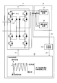
- FIG. 2 is a diagram illustrating a configuration example of the power conversion device according to the first embodiment.
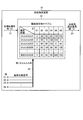
- FIG. 3 is a diagram for explaining the operation of the phase angle determination unit according to the first embodiment.
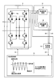
- FIG. 4 is a diagram illustrating a configuration example of the power conversion device according to the second embodiment.
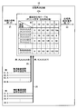
- FIG. 5 is a diagram for explaining the operation of the phase angle determination unit according to the second embodiment.
- FIG. 6 is a diagram illustrating a configuration example of a power conversion device according to the third embodiment.
- FIG. 7 is a diagram for explaining the operation of the input / output performance adjustment unit according to the third embodiment.
- FIG. 1 is a diagram illustrating an example of the overall configuration of a train set equipped with the power conversion device according to Embodiment 1 of the present invention.
- the train set equipped with the power conversion device according to Embodiment 1 has a pantograph 1, a transformer 2, wheels 3, a power conversion device 4, and a load device group 12 in one vehicle.
- a single train train is provided with a plurality of power conversion devices 4.
- the pantograph 1, the transformer 2, and the wheel 3 are connected in series between an overhead line 5 that serves as a power supply source (power source) and the line 6, and the power conversion device 4 receives AC power supplied from the transformer 2.
- the DC power is converted to DC power, and the converted DC power is supplied to the load device group 12.
- FIG. 2 is a diagram illustrating a configuration example of the power conversion device according to the first embodiment.
- the power conversion device 4 includes a converter 11, a phase angle determination unit 15, and a PWM control unit 16.
- the converter 11 is a power converter that converts an input AC voltage into a DC voltage, and includes a plurality of switching elements 11a and a plurality of diodes 11b, and is configured as a known three-level converter.
- 2 illustrates a three-level converter, a configuration other than the three-level converter (for example, a two-level converter) may be employed.
- the load device group 12 is a component that collectively refers to the propulsion control device 13 and the auxiliary power supply device 14.
- the propulsion control device 13 is a device used for electric vehicle propulsion control, and drives the electric vehicle by generating a driving force by a power converter (inverter) and a main motor (not shown).
- the auxiliary power supply 14 is a power supply that supplies power to devices other than the main motor, and supplies required power to a brake device, a lighting device, a door opening / closing device, an air conditioner, and the like that are not shown.
- the phase angle determination unit 15 is a component that determines the carrier phase angle to be given to the PWM control unit 16, and based on the load state signal 25 as the first signal indicating the load state of the propulsion control device 13.
- the phase angle setting signal 23 including the above information is generated and output to the PWM control unit 16.
- the PWM control unit 16 is a component that generates a PWM signal for controlling the switching element 11 a included in the converter 11, generates a PWM signal 19 based on the signal wave and the carrier wave, and outputs the PWM signal 19 to the converter 11.
- FIG. 3 is an explanatory diagram for explaining the operation of the phase angle determination unit 15 shown in FIG.
- the phase angle determination unit 15 is provided with a carrier phase table 22 referred to as the first table.
- the vehicle angle ID signal 21 and the load state signal 25 are input to the phase angle determination unit 15.
- the own vehicle ID signal 21 includes identification information (ID) for identifying a vehicle on which the power conversion device 4 is mounted among vehicles constituting the train set.
- ID may be a car number, or may be an identification number in which vehicles equipped with the power conversion device 4 are arranged in ascending order from 01.
- ID when ID is a car number, it does not necessarily become a serial number as shown in FIG. For example, in a 12-car train, when the power conversion device is mounted on the second car, the fifth car, the eighth car, and the eleventh car, the IDs are “02”, “05”, “08”, “11” from the left. "
- the load state shown on the front side of the carrier wave phase table 22 is information obtained by arranging information included in the load state signal 25 output from the propulsion control device 13 from the left for each ID.
- the load state of the propulsion control device mounted on the vehicle of ID06 is “B”, and the other propulsion control is performed.
- the load state of the device is “A”.
- the load state is an index for embodying the concept of managing the same load state as one group.
- the load states “A” are a group of items that can be regarded as the same load state
- the load state “B” is a group of items that can be regarded as different from the load state “A”. Group.
- FIG. 3 shows an example in which the load state “A” and the load state “B” are divided into two groups, but it is of course possible to divide into three or more groups.
- the phase angle set in the carrier wave phase table 22 is the carrier wave phase angle shown in the PWM control unit 16 of FIG. 2, and a predetermined phase in the signal wave is set as a reference phase, for example, the peak of the carrier wave is determined from this reference phase.
- This is a phase angle that enables the PWM controller 16 to generate a carrier wave shifted by the carrier wave phase angle.
- the signal wave and the reference phase are common to the converter 11 mounted on each vehicle. For this reason, the PWM signal generated by the converter 11 is a signal whose phase is shifted by the phase angle set in the table shown in FIG.
- the power conversion devices (converters) of ID01 to 06 are Phase angles in the range from 0 to 150 ° are set at equal intervals in steps of 30 °.
- the reason why the carrier phase angle is set in this way is to reduce the harmonic component generated by the carrier wave.
- components with a phase angle of 30 ° in the range from 0 to 150 ° are 0 °, 30 °, 60 °, 90 °, 120 °, and 150 °, and 0 is a component that is a double of this phase angle.
- the carrier phase angle for ID01 to 06 is 0 respectively. °, 60 °, 120 °, 30 °, 90 °, and 150 ° are set. Therefore, the phase angles of the first group grouped by the load state A are 0 °, 60 °, and 120 °, and the vector sum of 0 °, 120 °, and 240 ° that is a component obtained by doubling these is zero. Become.
- phase angles of the second group grouped according to the load state B are 30 °, 90 °, and 150 °, and the vector sum of 60 °, 180 °, and 300 °, which are components obtained by doubling these, is zero. It is. Therefore, it is possible to suppress the generation of harmonics for each group grouped by the load states A and B.
- phase angle determination unit 15 when the vehicle ID signal 21 and the load state signal 25 are input will be described with reference to FIG.
- a host vehicle ID signal 21 having an ID of 03 for example, is input from a host control device
- the phase angle determination unit 15 recognizes that the vehicle has its own ID of 03.
- the ID signal may be input constantly or periodically. Moreover, it does not need to be input when the system is started and not when the train is operated.
- the phase angle determination unit 15 recognizes from the load state signal 25 that the load state of the propulsion control device 13 is (A, A, A, A, A, B), and 2 rows and 3 columns of the carrier phase table 22
- the value “72” described in the third column (ID “03” column in the third column) is referred to, the phase angle setting signal 23 includes the reference value “72 °”, and is output to the PWM controller 16. As described above, this value is referred to in the PWM control unit 16 and a carrier wave having a phase difference of 72 ° from the reference phase is generated.
- FIG. 1 demonstrated the structure by which one power converter device is connected to a transformer
- the structure by which several power converter devices are connected to a transformer may be sufficient.
- Heat generation can be suppressed, which can contribute to efficient operation of the transformer.
- the control method according to the first embodiment is effective even when connected vehicles and vehicles to which both the propulsion control device 13 and the auxiliary power supply device 14 are connected are mixed.
- the carrier phase table 22 shown in FIG. 3 is applied to a vehicle group to which only the propulsion control device 13 is connected and to a vehicle group to which both the propulsion control device 13 and the auxiliary power supply device 14 are connected. What is necessary is just to hold separately and the effect demonstrated in this Embodiment can be acquired.
- the propulsion control devices that control the propulsion of the electric vehicle are grouped in the same group, and the phase angle within the same group is grouped. Is provided for each group, and each time the first signal indicating the load state of the propulsion control device is input or changed, the phase angle of the carrier wave used when generating the PWM signal is set. Since it was decided to set or change the phase angle described in the first table, even if the operation state of the propulsion control device is different and as a result, the load state of the power conversion device is different. In addition, it is possible to effectively suppress harmonic components generated in the power converter.
- FIG. FIG. 4 is a diagram illustrating a configuration example of the power conversion device according to the second embodiment of the present invention.
- a load state signal 26 as a second signal indicating the load state of the auxiliary power supply device 14 is input to the phase angle determination unit 15. Configuration is added.
- another structure it is the same as that of Embodiment 1, or is the same,
- symbol is attached
- FIG. 5 is an explanatory diagram for explaining the operation of the phase angle determination unit 15 according to the second embodiment shown in FIG.
- the phase angle determination unit 15 is provided with a carrier wave phase table 22a referred to as a second table.
- the vehicle ID signal 21 and the load state signals 25 and 26 are input to the phase angle determination unit 15.
- the information included in the load state signal 25 output from the propulsion control device 13 is listed from the left for each ID, and output from the auxiliary power supply device 14.
- the information included in the load state signal 26 is shown together with the information arranged from the left for each ID.
- the load states (A, A, A, A, B) and (X, X, X, X, X, Y) shown in the second row are propulsion mounted on the vehicles of ID01 to 05.
- Auxiliary power supply device in which the load state of the control device is “A” and the load state of the propulsion control device mounted on the vehicle of ID06 is “B” and is mounted on the vehicles of ID01 to 05
- the load state is “X” and the load state of the auxiliary power supply device mounted on the vehicle of ID06 is “Y”.
- FIG. 5 shows an example in which the load state of the auxiliary power supply device is divided into two groups of load state “X” and load state “Y”, but it is needless to say that the load state is divided into three or more groups. Is possible.
- A 1000 kW
- B 950 kW
- X 100 kW
- (A, X) represents a weakly cooled vehicle
- (B, Y) represents a load state of a normal cooled vehicle.
- the load states of the propulsion control device 13 and the auxiliary power supply device 14 are (A, A, A, A, A) and (X, X, X, X, X) as shown in the first row of FIG. , X), the phase angle in the range of 0 to 150 ° is set at equal intervals in increments of 30 ° with respect to the power conversion device 4 (converter 11) of ID01 to 06.
- these set values are the same as the set values shown in the first row of FIG. 3, and that even-numbered harmonic components including second-order harmonic components can be effectively suppressed as described above. It is.
- IDs 01 to 06 are set to 0 °, 45 °, 90 °, 135 °, 0 °, and 90 °, respectively. Therefore, the phase angles of the first group grouped by the pair (A, X) of the load state are 0 °, 45 °, 90 °, and 135 °, and 0 ° and 90 ° that are components obtained by doubling these. , 180 °, 270 °, the vector sum becomes zero, and the harmonics in the group are suppressed.
- phase angle of the second group grouped by the pair (B, Y) of the load state is 0 ° and 90 °, and the vector sum of 0 ° and 180 °, which is a component obtained by doubling these, is also zero. It is. Therefore, it is possible to suppress the generation of harmonics for each group grouped by the pair (A, X) and (B, Y) of the load state.
- FIG. 4 the configuration in which both the propulsion control device 13 and the auxiliary power supply device 14 are connected to the converter 11 is disclosed. However, in each vehicle in which the power conversion device 4 is mounted, only the propulsion control device 13 is included in the converter 11.
- the control method according to the second embodiment is effective even when vehicles to be connected and vehicles to which both the propulsion control device 13 and the auxiliary power supply device 14 are connected are mixed.
- the load state “Y” of the auxiliary power supply device 14 indicates that the auxiliary power supply device 14 has failed, is in an operating state corresponding to the failure, or does not have the auxiliary power supply device 14. If it defines as time, the case where the vehicle which does not have the auxiliary power supply device 14 exists can be included. If defined in this way, for example, a vehicle in which the auxiliary power supply device fails and the propulsion control device is effective can be managed in the same group as a vehicle that does not have the auxiliary power supply device.
- the combination of the load state of the propulsion control device for propulsion control of the electric vehicle and the load state of the auxiliary power supply device can be regarded as the same group.
- a second table is provided in which the set values of the phase angle within the same group are described for each group, and a second signal representing the load state of the propulsion control device and the auxiliary power supply device is input or changed. Since the phase angle of the carrier wave used for generating the PWM signal is set or changed to the phase angle described in the second table, the operation state of the propulsion control device and / or the auxiliary power supply device is different. As a result, even when the load state of the power converter is different, the harmonic component generated in the power converter can be effectively suppressed.
- FIG. FIG. 6 is a diagram illustrating a configuration example of the power conversion device according to the third embodiment of the present invention.
- a load state signal 26 indicating the load state of the auxiliary power supply device 14 is input, and a third for adjusting the output of the propulsion control device 13.
- an input / output performance adjustment unit 17 that generates and outputs a performance command signal 28 that is a signal of
- an input / output performance adjustment unit 17 that generates and outputs a performance command signal 28 that is a signal of
- an input / output performance adjustment unit 17 that generates and outputs a performance command signal 28 that is a signal of
- an input / output performance adjustment unit 17 that generates and outputs a performance command signal 28 that is a signal of
- another structure it is the same as that of Embodiment 2, or is equivalent,
- symbol is attached
- FIG. 7 is an explanatory diagram for explaining the operation of the input / output performance adjustment unit 17 according to the third embodiment shown in FIG.
- the input / output performance adjustment unit 17 is provided with a performance setting table 27 referred to as a third table.
- the vehicle ID signal 21 and the load state signal 26 are input to the input / output performance adjustment unit 17.
- the creation of the performance setting table 27 is equivalent to the carrier phase table 22 shown in FIG. 3.
- the table value described in the carrier wave phase table 22 is the phase angle of the carrier wave
- the table value described in the performance setting table 27 is a performance value to be given to the propulsion control device 13.
- performance setting values set in the performance value setting table 27 will be described.
- the load state of the auxiliary power supply device 14 is (X, X, X, X, X, X) as shown in the first row of FIG. 7, the power conversion device 4 (converter 11) of ID01 to 06 is used.
- 200 kW which is the rated power of the propulsion control device 13 is set.
- ID01 to 04 For example, 1000 kW is set as each performance setting value for the propulsion control device 13, and 950 kW is set as each performance setting value for the propulsion control device 13 with ID 05,06.
- the power conversion device of the present embodiment is configured such that the propulsion control device 13 and the auxiliary power supply device 14 are connected to the same converter 11, the propulsion is performed when the load state of the auxiliary power supply device 14 is high. On the contrary, it is preferable that the output of the control device 13 is reduced. This is because, when performing control for canceling harmonics with equivalent outputs of the converter 11, it is preferable to output propulsion control required as a train without excess or deficiency together with this control. It is. Therefore, in the power conversion device according to the present embodiment, devices that can be regarded as having the same load state of the propulsion control device 13 are grouped into the same group and set to the same performance value in the same group unit.
- the input / output performance adjusting unit 17 when the vehicle ID signal 21 and the load state signal 26 are input will be described with reference to FIG.
- the input / output performance adjustment unit 17 recognizes that the vehicle has its own ID of 03.
- the ID signal may be input constantly or periodically. Moreover, it does not need to be input when the system is started and not when the train is operated.
- the input / output performance adjustment unit 17 recognizes from the load state signal 26 that the load state of the auxiliary power supply device 14 is (X, X, X, X, Y), and the performance value setting table 27 has two rows.
- the performance command signal 28 includes the reference value “1000 kW” and outputs it to the propulsion control device 13. As described above, this value is set in the propulsion control device 13 and the propulsion control device 13 operates based on this set value.
- the configuration in which the input / output performance adjustment unit 17 is applied to the power conversion device according to the second embodiment illustrated in FIG. 4 is illustrated as an example.
- the configuration to be provided may be applied to the power conversion device according to the first embodiment shown in FIG.
- those that can be regarded as having the same load state of the auxiliary power supply device are grouped into the same group, and the performance values given to the propulsion control device are the same within the group.
- a third table is provided. Therefore, the operation state of the auxiliary power supply device is different, and as a result, the operation state of the entire power conversion device is suitably controlled, and harmonic components generated in the power conversion device are reduced. It becomes possible to suppress effectively.
- Embodiments 1 to 3 above are examples of the configuration of the present invention, and can be combined with other known techniques, and can be combined within the scope of the present invention. Needless to say, the configuration may be modified by omitting the unit.
- the present invention is useful as a power conversion device that can enhance the effect of suppressing harmonics.
Landscapes
- Engineering & Computer Science (AREA)
- Power Engineering (AREA)
- Transportation (AREA)
- Mechanical Engineering (AREA)
- Life Sciences & Earth Sciences (AREA)
- Sustainable Development (AREA)
- Sustainable Energy (AREA)
- Electric Propulsion And Braking For Vehicles (AREA)
- Rectifiers (AREA)
Priority Applications (7)
| Application Number | Priority Date | Filing Date | Title |
|---|---|---|---|
| EP11877578.2A EP2793385B1 (en) | 2011-12-12 | 2011-12-12 | Electric power conversion device |
| IN4877CHN2014 IN2014CN04877A (enExample) | 2011-12-12 | 2011-12-12 | |
| KR1020147017214A KR101656590B1 (ko) | 2011-12-12 | 2011-12-12 | 전력 변환 장치 |
| US14/364,653 US9393871B2 (en) | 2011-12-12 | 2011-12-12 | Power conversion device |
| CN201180075428.7A CN103988409B (zh) | 2011-12-12 | 2011-12-12 | 功率转换装置 |
| JP2013548973A JP5693752B2 (ja) | 2011-12-12 | 2011-12-12 | 電力変換装置 |
| PCT/JP2011/078694 WO2013088496A1 (ja) | 2011-12-12 | 2011-12-12 | 電力変換装置 |
Applications Claiming Priority (1)
| Application Number | Priority Date | Filing Date | Title |
|---|---|---|---|
| PCT/JP2011/078694 WO2013088496A1 (ja) | 2011-12-12 | 2011-12-12 | 電力変換装置 |
Publications (1)
| Publication Number | Publication Date |
|---|---|
| WO2013088496A1 true WO2013088496A1 (ja) | 2013-06-20 |
Family
ID=48611985
Family Applications (1)
| Application Number | Title | Priority Date | Filing Date |
|---|---|---|---|
| PCT/JP2011/078694 Ceased WO2013088496A1 (ja) | 2011-12-12 | 2011-12-12 | 電力変換装置 |
Country Status (7)
| Country | Link |
|---|---|
| US (1) | US9393871B2 (enExample) |
| EP (1) | EP2793385B1 (enExample) |
| JP (1) | JP5693752B2 (enExample) |
| KR (1) | KR101656590B1 (enExample) |
| CN (1) | CN103988409B (enExample) |
| IN (1) | IN2014CN04877A (enExample) |
| WO (1) | WO2013088496A1 (enExample) |
Cited By (2)
| Publication number | Priority date | Publication date | Assignee | Title |
|---|---|---|---|---|
| JP2016185007A (ja) * | 2015-03-26 | 2016-10-20 | 株式会社日立製作所 | 車両駆動システム |
| JP6425855B1 (ja) * | 2018-01-22 | 2018-11-21 | 三菱電機株式会社 | 電力変換装置 |
Families Citing this family (3)
| Publication number | Priority date | Publication date | Assignee | Title |
|---|---|---|---|---|
| EP3392908B1 (de) * | 2017-04-20 | 2019-07-24 | Infineon Technologies AG | Leistungshalbleiteranordnung mit einem stapel von eine verbesserte geometrie aufweisenden anschlussplatten zur gemeinsamen elektrischen kontaktierungen mehrerer, gleichartiger leistungshalbleiter-schaltelemente |
| US20180361830A1 (en) * | 2017-06-19 | 2018-12-20 | Ford Global Technologies, Llc | Dual electric drive a/c compressor system and method |
| KR102221347B1 (ko) | 2018-12-28 | 2021-03-03 | 우리산업 주식회사 | 전자기 변속 스위치 블록 일체형 열발전 탑재 3상 권선 가변구조의 모터 구동 시스템 |
Citations (3)
| Publication number | Priority date | Publication date | Assignee | Title |
|---|---|---|---|---|
| JPH07274517A (ja) | 1994-03-28 | 1995-10-20 | Central Japan Railway Co | Pwmコンバータの制御装置 |
| WO1998043848A1 (fr) * | 1997-03-31 | 1998-10-08 | Mitsubishi Denki Kabushiki Kaisha | Appareil de commande de convertisseur a modulation d'impulsions en largeur |
| JP2010130850A (ja) * | 2008-11-28 | 2010-06-10 | Toshiba Corp | 電気車用電力変換装置 |
Family Cites Families (14)
| Publication number | Priority date | Publication date | Assignee | Title |
|---|---|---|---|---|
| JPH0667045B2 (ja) | 1986-03-12 | 1994-08-24 | 富士電機株式会社 | Pwmコンバ−タの制御方法 |
| JP3050234B2 (ja) | 1990-04-27 | 2000-06-12 | 株式会社東芝 | 電鉄用電動機主回路 |
| JPH07123501A (ja) * | 1993-10-28 | 1995-05-12 | Toshiba Corp | 電気車制御装置 |
| JPH0898317A (ja) | 1994-09-19 | 1996-04-12 | Mitsubishi Electric Corp | 交流電気車の制御装置 |
| JP3535001B2 (ja) * | 1998-01-22 | 2004-06-07 | 三菱電機株式会社 | 電源装置およびその起動方法 |
| JP2006025591A (ja) * | 2004-06-08 | 2006-01-26 | Toshiba Corp | 車両用電源装置 |
| CN100568699C (zh) * | 2004-07-20 | 2009-12-09 | 松下电器产业株式会社 | 变换器装置 |
| CN2774057Y (zh) * | 2005-01-18 | 2006-04-19 | 岳阳高新技术产业开发区天元电子技术有限公司 | 移动机车感应无线车上检测地址装置 |
| JP4410769B2 (ja) * | 2006-04-11 | 2010-02-03 | 三菱電機株式会社 | 交流列車車両用の電力変換システム |
| JP4711939B2 (ja) | 2006-11-27 | 2011-06-29 | 三菱電機株式会社 | 交流電気車の制御装置 |
| JP5209922B2 (ja) * | 2007-09-14 | 2013-06-12 | 川崎重工業株式会社 | 電気鉄道システム |
| JP4643670B2 (ja) * | 2008-03-07 | 2011-03-02 | 株式会社東芝 | 電気車駆動装置 |
| JP5198232B2 (ja) | 2008-11-27 | 2013-05-15 | 株式会社東芝 | 電力変換装置 |
| JP5119222B2 (ja) * | 2009-08-31 | 2013-01-16 | 株式会社日立産機システム | コンバータ装置、モータ駆動用モジュール及び冷凍装置 |
-
2011
- 2011-12-12 IN IN4877CHN2014 patent/IN2014CN04877A/en unknown
- 2011-12-12 CN CN201180075428.7A patent/CN103988409B/zh active Active
- 2011-12-12 JP JP2013548973A patent/JP5693752B2/ja active Active
- 2011-12-12 WO PCT/JP2011/078694 patent/WO2013088496A1/ja not_active Ceased
- 2011-12-12 EP EP11877578.2A patent/EP2793385B1/en active Active
- 2011-12-12 US US14/364,653 patent/US9393871B2/en active Active
- 2011-12-12 KR KR1020147017214A patent/KR101656590B1/ko not_active Expired - Fee Related
Patent Citations (3)
| Publication number | Priority date | Publication date | Assignee | Title |
|---|---|---|---|---|
| JPH07274517A (ja) | 1994-03-28 | 1995-10-20 | Central Japan Railway Co | Pwmコンバータの制御装置 |
| WO1998043848A1 (fr) * | 1997-03-31 | 1998-10-08 | Mitsubishi Denki Kabushiki Kaisha | Appareil de commande de convertisseur a modulation d'impulsions en largeur |
| JP2010130850A (ja) * | 2008-11-28 | 2010-06-10 | Toshiba Corp | 電気車用電力変換装置 |
Cited By (3)
| Publication number | Priority date | Publication date | Assignee | Title |
|---|---|---|---|---|
| JP2016185007A (ja) * | 2015-03-26 | 2016-10-20 | 株式会社日立製作所 | 車両駆動システム |
| JP6425855B1 (ja) * | 2018-01-22 | 2018-11-21 | 三菱電機株式会社 | 電力変換装置 |
| WO2019142361A1 (ja) * | 2018-01-22 | 2019-07-25 | 三菱電機株式会社 | 電力変換装置 |
Also Published As
| Publication number | Publication date |
|---|---|
| US9393871B2 (en) | 2016-07-19 |
| IN2014CN04877A (enExample) | 2015-09-18 |
| CN103988409A (zh) | 2014-08-13 |
| US20140343778A1 (en) | 2014-11-20 |
| EP2793385A4 (en) | 2016-10-26 |
| KR101656590B1 (ko) | 2016-09-09 |
| EP2793385A1 (en) | 2014-10-22 |
| KR20140094641A (ko) | 2014-07-30 |
| EP2793385B1 (en) | 2021-08-04 |
| CN103988409B (zh) | 2016-06-29 |
| JPWO2013088496A1 (ja) | 2015-04-27 |
| JP5693752B2 (ja) | 2015-04-01 |
Similar Documents
| Publication | Publication Date | Title |
|---|---|---|
| US9712090B2 (en) | Driving device for motor for drive wheel of vehicle | |
| CN108336943B (zh) | 电驱动系统和车辆 | |
| JP4297971B2 (ja) | 電動機制御装置 | |
| JP5693752B2 (ja) | 電力変換装置 | |
| US10075097B2 (en) | Power conversion device and AC electric-vehicle drive system | |
| JP6662669B2 (ja) | 電力変換装置 | |
| KR20160100346A (ko) | 다중-레벨 회생 드라이브를 위한 버스 커패시터 뱅크 구성 | |
| JP2019170044A (ja) | システム | |
| EP3083468B1 (en) | Pwm strategy for regenerative multilevel drive | |
| JP5352731B2 (ja) | 鉄道編成車両の駆動システム | |
| JP6393643B2 (ja) | 車両駆動システム | |
| JP5373644B2 (ja) | 編成車両の制御方法及び制御装置 | |
| WO2018127945A1 (ja) | 電力変換装置 | |
| CN111332122B (zh) | 采用分布式小功率电源模块的供电系统 | |
| JP4838031B2 (ja) | 多重インバータの制御システム | |
| JP2015198544A (ja) | 駆動システム | |
| Chulan et al. | Seven levels symmetric H-bridge multilevel inverter with less number of switching devices | |
| KR20190022203A (ko) | 필터를 최소화하는 병렬 운전 시스템 | |
| WO2013001828A1 (ja) | インバータ | |
| JPH0993702A (ja) | 鉄道車両用電力変換装置 |
Legal Events
| Date | Code | Title | Description |
|---|---|---|---|
| 121 | Ep: the epo has been informed by wipo that ep was designated in this application |
Ref document number: 11877578 Country of ref document: EP Kind code of ref document: A1 |
|
| ENP | Entry into the national phase |
Ref document number: 2013548973 Country of ref document: JP Kind code of ref document: A |
|
| WWE | Wipo information: entry into national phase |
Ref document number: 14364653 Country of ref document: US |
|
| NENP | Non-entry into the national phase |
Ref country code: DE |
|
| ENP | Entry into the national phase |
Ref document number: 20147017214 Country of ref document: KR Kind code of ref document: A |
|
| WWE | Wipo information: entry into national phase |
Ref document number: 2011877578 Country of ref document: EP |