WO2013084358A1 - 車両の制御装置 - Google Patents
車両の制御装置 Download PDFInfo
- Publication number
- WO2013084358A1 WO2013084358A1 PCT/JP2011/078589 JP2011078589W WO2013084358A1 WO 2013084358 A1 WO2013084358 A1 WO 2013084358A1 JP 2011078589 W JP2011078589 W JP 2011078589W WO 2013084358 A1 WO2013084358 A1 WO 2013084358A1
- Authority
- WO
- WIPO (PCT)
- Prior art keywords
- regenerative
- brake device
- brake
- range
- regenerative brake
- Prior art date
Links
Images


Classifications
-
- B—PERFORMING OPERATIONS; TRANSPORTING
- B60—VEHICLES IN GENERAL
- B60W—CONJOINT CONTROL OF VEHICLE SUB-UNITS OF DIFFERENT TYPE OR DIFFERENT FUNCTION; CONTROL SYSTEMS SPECIALLY ADAPTED FOR HYBRID VEHICLES; ROAD VEHICLE DRIVE CONTROL SYSTEMS FOR PURPOSES NOT RELATED TO THE CONTROL OF A PARTICULAR SUB-UNIT
- B60W10/00—Conjoint control of vehicle sub-units of different type or different function
- B60W10/18—Conjoint control of vehicle sub-units of different type or different function including control of braking systems
- B60W10/184—Conjoint control of vehicle sub-units of different type or different function including control of braking systems with wheel brakes
-
- B—PERFORMING OPERATIONS; TRANSPORTING
- B60—VEHICLES IN GENERAL
- B60K—ARRANGEMENT OR MOUNTING OF PROPULSION UNITS OR OF TRANSMISSIONS IN VEHICLES; ARRANGEMENT OR MOUNTING OF PLURAL DIVERSE PRIME-MOVERS IN VEHICLES; AUXILIARY DRIVES FOR VEHICLES; INSTRUMENTATION OR DASHBOARDS FOR VEHICLES; ARRANGEMENTS IN CONNECTION WITH COOLING, AIR INTAKE, GAS EXHAUST OR FUEL SUPPLY OF PROPULSION UNITS IN VEHICLES
- B60K6/00—Arrangement or mounting of plural diverse prime-movers for mutual or common propulsion, e.g. hybrid propulsion systems comprising electric motors and internal combustion engines ; Control systems therefor, i.e. systems controlling two or more prime movers, or controlling one of these prime movers and any of the transmission, drive or drive units Informative references: mechanical gearings with secondary electric drive F16H3/72; arrangements for handling mechanical energy structurally associated with the dynamo-electric machine H02K7/00; machines comprising structurally interrelated motor and generator parts H02K51/00; dynamo-electric machines not otherwise provided for in H02K see H02K99/00
- B60K6/20—Arrangement or mounting of plural diverse prime-movers for mutual or common propulsion, e.g. hybrid propulsion systems comprising electric motors and internal combustion engines ; Control systems therefor, i.e. systems controlling two or more prime movers, or controlling one of these prime movers and any of the transmission, drive or drive units Informative references: mechanical gearings with secondary electric drive F16H3/72; arrangements for handling mechanical energy structurally associated with the dynamo-electric machine H02K7/00; machines comprising structurally interrelated motor and generator parts H02K51/00; dynamo-electric machines not otherwise provided for in H02K see H02K99/00 the prime-movers consisting of electric motors and internal combustion engines, e.g. HEVs
- B60K6/42—Arrangement or mounting of plural diverse prime-movers for mutual or common propulsion, e.g. hybrid propulsion systems comprising electric motors and internal combustion engines ; Control systems therefor, i.e. systems controlling two or more prime movers, or controlling one of these prime movers and any of the transmission, drive or drive units Informative references: mechanical gearings with secondary electric drive F16H3/72; arrangements for handling mechanical energy structurally associated with the dynamo-electric machine H02K7/00; machines comprising structurally interrelated motor and generator parts H02K51/00; dynamo-electric machines not otherwise provided for in H02K see H02K99/00 the prime-movers consisting of electric motors and internal combustion engines, e.g. HEVs characterised by the architecture of the hybrid electric vehicle
- B60K6/44—Series-parallel type
- B60K6/445—Differential gearing distribution type
-
- B—PERFORMING OPERATIONS; TRANSPORTING
- B60—VEHICLES IN GENERAL
- B60W—CONJOINT CONTROL OF VEHICLE SUB-UNITS OF DIFFERENT TYPE OR DIFFERENT FUNCTION; CONTROL SYSTEMS SPECIALLY ADAPTED FOR HYBRID VEHICLES; ROAD VEHICLE DRIVE CONTROL SYSTEMS FOR PURPOSES NOT RELATED TO THE CONTROL OF A PARTICULAR SUB-UNIT
- B60W10/00—Conjoint control of vehicle sub-units of different type or different function
- B60W10/04—Conjoint control of vehicle sub-units of different type or different function including control of propulsion units
- B60W10/06—Conjoint control of vehicle sub-units of different type or different function including control of propulsion units including control of combustion engines
-
- B—PERFORMING OPERATIONS; TRANSPORTING
- B60—VEHICLES IN GENERAL
- B60W—CONJOINT CONTROL OF VEHICLE SUB-UNITS OF DIFFERENT TYPE OR DIFFERENT FUNCTION; CONTROL SYSTEMS SPECIALLY ADAPTED FOR HYBRID VEHICLES; ROAD VEHICLE DRIVE CONTROL SYSTEMS FOR PURPOSES NOT RELATED TO THE CONTROL OF A PARTICULAR SUB-UNIT
- B60W10/00—Conjoint control of vehicle sub-units of different type or different function
- B60W10/04—Conjoint control of vehicle sub-units of different type or different function including control of propulsion units
- B60W10/08—Conjoint control of vehicle sub-units of different type or different function including control of propulsion units including control of electric propulsion units, e.g. motors or generators
-
- B—PERFORMING OPERATIONS; TRANSPORTING
- B60—VEHICLES IN GENERAL
- B60W—CONJOINT CONTROL OF VEHICLE SUB-UNITS OF DIFFERENT TYPE OR DIFFERENT FUNCTION; CONTROL SYSTEMS SPECIALLY ADAPTED FOR HYBRID VEHICLES; ROAD VEHICLE DRIVE CONTROL SYSTEMS FOR PURPOSES NOT RELATED TO THE CONTROL OF A PARTICULAR SUB-UNIT
- B60W20/00—Control systems specially adapted for hybrid vehicles
- B60W20/50—Control strategies for responding to system failures, e.g. for fault diagnosis, failsafe operation or limp mode
-
- B—PERFORMING OPERATIONS; TRANSPORTING
- B60—VEHICLES IN GENERAL
- B60W—CONJOINT CONTROL OF VEHICLE SUB-UNITS OF DIFFERENT TYPE OR DIFFERENT FUNCTION; CONTROL SYSTEMS SPECIALLY ADAPTED FOR HYBRID VEHICLES; ROAD VEHICLE DRIVE CONTROL SYSTEMS FOR PURPOSES NOT RELATED TO THE CONTROL OF A PARTICULAR SUB-UNIT
- B60W30/00—Purposes of road vehicle drive control systems not related to the control of a particular sub-unit, e.g. of systems using conjoint control of vehicle sub-units, or advanced driver assistance systems for ensuring comfort, stability and safety or drive control systems for propelling or retarding the vehicle
- B60W30/18—Propelling the vehicle
- B60W30/18009—Propelling the vehicle related to particular drive situations
- B60W30/18109—Braking
- B60W30/18127—Regenerative braking
-
- B—PERFORMING OPERATIONS; TRANSPORTING
- B60—VEHICLES IN GENERAL
- B60W—CONJOINT CONTROL OF VEHICLE SUB-UNITS OF DIFFERENT TYPE OR DIFFERENT FUNCTION; CONTROL SYSTEMS SPECIALLY ADAPTED FOR HYBRID VEHICLES; ROAD VEHICLE DRIVE CONTROL SYSTEMS FOR PURPOSES NOT RELATED TO THE CONTROL OF A PARTICULAR SUB-UNIT
- B60W20/00—Control systems specially adapted for hybrid vehicles
- B60W20/10—Controlling the power contribution of each of the prime movers to meet required power demand
- B60W20/13—Controlling the power contribution of each of the prime movers to meet required power demand in order to stay within battery power input or output limits; in order to prevent overcharging or battery depletion
- B60W20/14—Controlling the power contribution of each of the prime movers to meet required power demand in order to stay within battery power input or output limits; in order to prevent overcharging or battery depletion in conjunction with braking regeneration
-
- B—PERFORMING OPERATIONS; TRANSPORTING
- B60—VEHICLES IN GENERAL
- B60W—CONJOINT CONTROL OF VEHICLE SUB-UNITS OF DIFFERENT TYPE OR DIFFERENT FUNCTION; CONTROL SYSTEMS SPECIALLY ADAPTED FOR HYBRID VEHICLES; ROAD VEHICLE DRIVE CONTROL SYSTEMS FOR PURPOSES NOT RELATED TO THE CONTROL OF A PARTICULAR SUB-UNIT
- B60W2540/00—Input parameters relating to occupants
- B60W2540/10—Accelerator pedal position
-
- B—PERFORMING OPERATIONS; TRANSPORTING
- B60—VEHICLES IN GENERAL
- B60W—CONJOINT CONTROL OF VEHICLE SUB-UNITS OF DIFFERENT TYPE OR DIFFERENT FUNCTION; CONTROL SYSTEMS SPECIALLY ADAPTED FOR HYBRID VEHICLES; ROAD VEHICLE DRIVE CONTROL SYSTEMS FOR PURPOSES NOT RELATED TO THE CONTROL OF A PARTICULAR SUB-UNIT
- B60W2540/00—Input parameters relating to occupants
- B60W2540/12—Brake pedal position
-
- Y—GENERAL TAGGING OF NEW TECHNOLOGICAL DEVELOPMENTS; GENERAL TAGGING OF CROSS-SECTIONAL TECHNOLOGIES SPANNING OVER SEVERAL SECTIONS OF THE IPC; TECHNICAL SUBJECTS COVERED BY FORMER USPC CROSS-REFERENCE ART COLLECTIONS [XRACs] AND DIGESTS
- Y02—TECHNOLOGIES OR APPLICATIONS FOR MITIGATION OR ADAPTATION AGAINST CLIMATE CHANGE
- Y02T—CLIMATE CHANGE MITIGATION TECHNOLOGIES RELATED TO TRANSPORTATION
- Y02T10/00—Road transport of goods or passengers
- Y02T10/60—Other road transportation technologies with climate change mitigation effect
- Y02T10/62—Hybrid vehicles
Definitions
- the present invention relates to a vehicle control device including a friction brake device and a regenerative brake device.
- a friction brake device generates braking force by pressing a brake shoe or brake pad against a brake drum or brake disc that rotates with the wheel, and changing the kinetic energy associated with the rotation of the wheel into thermal energy generated by the friction.
- the regenerative braking device normally generates a braking force by operating a motor used as a drive source as a generator, converting kinetic energy related to wheel rotation into electric energy and collecting it.
- a brake override system as shown in Patent Document 1 is known.
- the brake override system described in this document reduces the engine output by reducing the engine output by reducing the throttle valve when the accelerator operation (depressing the accelerator pedal) and the brake operation (depressing the brake pedal) are performed simultaneously.
- the vehicle braking based on the brake operation is prioritized over the vehicle acceleration based on the operation.
- the problem to be solved by the present invention is to provide a vehicle control device capable of simplifying a friction brake.
- a vehicle control device is a vehicle control device including a friction brake device and a regenerative brake device, and when the driver's accelerator operation and brake operation are performed simultaneously, Compared to when not, the range of use of the regenerative brake device is expanded.
- the use range of the regenerative brake device is expanded, and the share of the friction brake device in the entire braking force is reduced accordingly. . Therefore, the temperature increase of the friction brake device when the state where the driver's accelerator operation and the brake operation are simultaneously performed continues can be suppressed. Therefore, the configuration of the cooling device provided in the friction brake device can be simplified or eliminated, and the friction brake device can be simplified.
- the range of expansion of the use range of the regenerative brake device be reduced as the period during which the accelerator operation and the brake operation are performed simultaneously becomes longer.
- the vehicle driving force is reduced to give priority to braking of the vehicle based on the brake operation over acceleration of the vehicle based on the accelerator operation.
- the design of a vehicle that employs an override system is performed on the assumption that the accelerator operation and the brake operation are performed simultaneously. For this reason, the vehicle control apparatus of the present invention as described above is particularly suitable for application to a vehicle that employs such a brake override system.
- FIG. 1 is a schematic diagram schematically showing a configuration of a hybrid system and an electronically controlled brake system of a hybrid vehicle to which a first embodiment of the present invention is applied.
- the flowchart which shows the process sequence of the regenerative brake limit value increase control routine employ
- the graph which shows the relationship between the regenerative brake limit value at the time of simultaneous depression of the accelerator pedal and brake pedal in the same embodiment, and a required driving force.
- (A) is a time chart which shows an example of the control aspect of the brake control at the time of single depression of the brake pedal in the embodiment
- (b) is the time of simultaneous depression of the accelerator pedal and the brake pedal in the embodiment. It is a time chart which shows an example of the control aspect of this brake control.
- this hybrid vehicle includes a hybrid system having an engine 1 as a heat engine and two motor generators as a drive source.
- One of the two motor generators is mainly used for power generation, and the other is used for generating driving force.
- a motor generator mainly used for power generation is referred to as a generator 2
- a motor generator mainly used for generating a driving force is referred to as a motor 3.
- the hybrid system includes a power split mechanism 4 configured by a planetary gear mechanism.
- An engine 1, a generator 2, and a motor 3 are connected to the power split mechanism 4, respectively. Further, the power split mechanism 4 is connected to the drive wheels 6 via the speed reduction mechanism 5.
- the power split mechanism 4 divides the power generated by the engine 1 into power for driving the generator 2 and power for driving the drive wheels 6.
- the hybrid system includes a power control unit 7.
- the power control unit 7 has a boost converter and an inverter.
- the boost converter boosts the voltage of the hybrid battery 8 to a voltage necessary for driving the generator 2 and the motor 3.
- the inverter converts the high-voltage direct current boosted by the boost converter into an alternating current supplied to the generator 2 and the motor 3, and when the generator 2 and the motor 3 function as a generator, the alternating current generated by them Is converted to a direct current.
- this hybrid vehicle is equipped with an electronically controlled brake system.
- the electronically controlled brake system includes a hydraulic friction brake device 11 provided on each wheel of the hybrid vehicle, and a motor 3 that performs regenerative power generation so as to function as a regenerative brake device.
- the electronically controlled brake system generates a braking force by the friction brake device 11 and the motor 3 that performs regenerative power generation in response to the driver's depression of the brake pedal (brake operation member) 9.
- the brake pedal 9 is connected to a master cylinder 10 that generates hydraulic pressure (master cylinder pressure) in response to the depression.
- the master cylinder 10 is provided with a hydro booster that assists the driver's depression force of the brake pedal 9 to increase the brake hydraulic pressure.
- the master cylinder pressure generated by the master cylinder 10 is input to the brake actuator 12.
- the brake actuator 12 adjusts the master cylinder pressure to form a hydraulic pressure (brake hydraulic pressure) used for the operation of each friction brake device 11.
- the master cylinder pressure generated by the master cylinder 10 is also input to the stroke simulator 13.
- the stroke simulator 13 generates a natural pedal stroke according to the depression force of the brake pedal 9 by introducing the master cylinder pressure into the built-in stroke simulator cylinder.
- the electronically controlled brake system includes a skid control computer 14 as a control unit.
- the skid control computer 14 receives detection signals from sensors such as a brake pedal stroke sensor 15 that detects the depression amount (brake operation amount) of the brake pedal 9 and a wheel speed sensor 16 that detects the rotation speed (wheel speed) of each wheel. Have been entered.
- the skid control computer 14 is connected to a power management control computer 17 that controls the power control unit 7 through an in-vehicle LAN.
- the power management control computer 17 receives a detection signal of an accelerator pedal stroke sensor 19 that detects the amount of depression (accelerator operation amount) of an accelerator pedal (accelerator operation member) 18. Then, the skid control computer 14 confirms the accelerator operation amount through communication from the power management control computer 17.
- the brake control is performed by the skid control computer 14.
- the skid control computer 14 calculates the required total braking force from the brake operation amount obtained from the detection signal of the brake pedal stroke sensor 15 and the vehicle speed obtained from the detection signal of the wheel speed sensor 16. To do.
- the skid control computer 14 determines a sharing ratio between the friction braking force by the friction brake device 11 and the regenerative braking force by the regenerative power generation of the motor 3 according to the current traveling state of the hybrid vehicle, and according to the sharing ratio. Then, the required friction braking force and the required regenerative braking force are calculated by assigning the required total braking force.
- a regenerative braking limit value calculated according to the vehicle speed or the like is set as an upper limit value, and the required regenerative braking force is calculated to be equal to or less than the regenerative braking limit value. That is, the upper limit value of the braking force generated by the motor 3 functioning as a regenerative brake device by performing regenerative power generation is set by the regenerative brake limit value.
- the skid control computer 14 controls the brake actuator 12 to adjust the brake hydraulic pressure supplied to the friction brake device 11 of each wheel so that the friction braking force corresponding to the required friction braking force can be obtained. Further, the skid control computer 14 transmits the requested regenerative braking force to the power management control computer 17.
- the power management control computer 17 controls the power control unit 7 based on the received requested regenerative braking force, and causes the motor 3 to perform regenerative power generation so that a regenerative braking force corresponding to the requested regenerative braking force is generated.
- a brake override system (BOS) is adopted for a hybrid vehicle equipped with such an electronically controlled brake system.
- BOS reduces the output of the hybrid system when the driver's accelerator operation (depressing the accelerator pedal) and brake operation (depressing the brake pedal 9) are performed at the same time.
- the acceleration of the hybrid vehicle based on the brake operation is prioritized for acceleration.
- the control related to the suppression of the temperature rise of the friction brake device 11 is performed through the processing of the regenerative brake limit value increase control routine shown in FIG.
- the processing of this routine is repeatedly executed at regular control intervals by the skid control computer 14 while the hybrid vehicle is traveling.
- step S100 When the processing of this routine is started, it is first determined in step S100 whether or not the accelerator pedal 18 and the brake pedal 9 are depressed simultaneously. If there is no simultaneous depression of these (S100: NO), the process of this routine is terminated as it is, and if not (S100: YES), the process proceeds to step S101.
- step S101 the regenerative brake limit is expanded, that is, the regenerative brake limit value is increased. Therefore, at this time, the upper limit value of the braking force generated by the motor 3 functioning as a regenerative braking device is increased by performing regenerative power generation.
- the regenerative brake limit at this time is expanded so that the larger the required driving force of the hybrid vehicle corresponding to the accelerator operation amount is, the larger the expansion range is. That is, as shown in FIG. 3, the regenerative brake limit value is increased as the required driving force increases and the driving force of the vehicle increases.
- the regenerative brake limit value is increased and the range of use of the regenerative brake device is expanded compared to when it is not. is doing. If the use range of the regenerative brake device is expanded, the share of the friction brake device in the entire braking force is reduced accordingly. Therefore, the temperature increase of the friction brake device when the state where the driver's accelerator operation and the brake operation are simultaneously performed is suppressed. Therefore, the configuration of the cooling device provided in the friction brake device can be simplified or eliminated, and the friction brake device can be simplified.
- the expansion of the range of use of the regenerative brake device when the accelerator pedal 18 and the brake pedal 9 are simultaneously depressed in this embodiment is performed through the process of the regenerative brake limit value increasing control routine shown in FIG.
- the processing of this routine is repeatedly executed at regular control intervals by the skid control computer 14 while the hybrid vehicle is traveling.
- step S200 When the processing of this routine is started, it is first determined in step S200 whether or not the accelerator pedal 18 and the brake pedal 9 are depressed simultaneously. If there is no simultaneous depression of these (S200: NO), the process of this routine is terminated as it is, and if not (S200: YES), the process proceeds to step S201.
- step S201 it is determined in step S201 whether or not the elapsed time since the simultaneous depression of the accelerator pedal 18 and the brake pedal 9 is started is equal to or less than a prescribed threshold value.
- a prescribed threshold value the maximum value of the time during which the state in which the use range of the regenerative brake device is expanded can be continued while the increase in the load of the motor 3 or the hybrid battery 8 is allowed is set.
- the elapsed time exceeds the threshold (S201: NO)
- the process of this routine is terminated as it is.
- step S202 the regenerative brake limit is expanded, that is, the regenerative brake limit value is increased, and then the process of this routine is terminated.
- the braking force of the regenerative braking device at this time is increased to the regenerative braking limit value that is increased according to the simultaneous depression of the accelerator pedal 18 and the brake pedal 9 according to the increase in the required total braking force.
- the elapsed time from the start of simultaneous depression of the accelerator pedal 18 and the brake pedal 9 reaches the time t1 when the threshold value is reached, the increased regenerative brake limit value is returned to the original value. Therefore, the braking force of the regenerative braking device is reduced, and the load on the motor 3 and the hybrid battery 8 is suppressed.
- the use range of the regenerative brake device is not expanded according to the simultaneous depression of the accelerator pedal 18 and the brake pedal 9.
- the use range of the regenerative brake device when the accelerator pedal 18 and the brake pedal 9 are simultaneously depressed is expanded through the process of the regenerative brake limit value increasing control routine shown in FIG.
- the processing of this routine is repeatedly executed at regular control intervals by the skid control computer 14 while the hybrid vehicle is traveling.
- step S300 When the processing of this routine is started, it is first determined in step S300 whether or not the accelerator pedal 18 and the brake pedal 9 are depressed simultaneously. If there is no simultaneous depression of these (S300: NO), the process of this routine is terminated as it is, and if not (S300: YES), the process proceeds to step S301.
- step S301 it is determined in step S301 whether or not the following conditions (A) to (D) are all satisfied.
- step S302 the regenerative brake limit is expanded, that is, the regenerative brake limit value is increased, and then the process of this routine is terminated.
- the larger the driving force of the hybrid vehicle the larger the range of use of the regenerative braking device is.
- the heat generation amount of the friction braking device 11 due to the increase of the driving force of the hybrid vehicle If the increase is sufficiently small, the range of expansion of the use range of the regenerative brake device may be constant regardless of the driving force of the hybrid vehicle.
- the expansion of the use range of the regenerative brake device is stopped, but the expansion is completely stopped.
- the expansion range of the use range of the regenerative brake device is reduced only once when the elapsed time from the start of simultaneous depression of the accelerator pedal 18 and the brake pedal 9 becomes a threshold.
- the range of use of the regenerative brake device may be gradually reduced or gradually reduced.
- the use range of the regenerative brake device is expanded according to the simultaneous depression of the accelerator pedal 18 and the brake pedal 9.
- one or more of the conditions (A) to (D) may be omitted.
- the condition (D) is omitted and the condition (A) is omitted.
- the use range of the regenerative braking device may be expanded in accordance with the simultaneous depression of the accelerator pedal 18 and the brake pedal 9.
- the range of use of the regenerative brake device corresponding to the simultaneous depression of the accelerator pedal 18 and the brake pedal 9 is increased by the friction braking force. You may make it variable according to a magnitude
- the range of expansion of the use range of the regenerative brake device according to the simultaneous depression of the accelerator pedal 18 and the brake pedal 9 is made variable according to the vehicle speed. May be.
- the temperature of the friction brake device 11 When the temperature of the friction brake device 11 is high in the first place, the temperature of the friction brake device 11 becomes higher due to an increase in the amount of heat generated with the expansion of the use range of the regenerative brake device, so that the accelerator pedal 18 and the brake pedal 9 can be depressed simultaneously.
- the expansion range of the use range of the corresponding regenerative brake device may be made variable according to the temperature of the friction brake device 11.
- the temperature of the friction brake device 11 can be directly detected, or can be estimated from the temperature of the brake oil, the use state of the friction brake device 11 until that time, the atmospheric temperature, and the like.
- the range of use of the regenerative brake device is expanded by increasing the regenerative brake limit value, that is, the upper limit value of the braking force (regenerative braking force) generated in the regenerative brake device.
- the use range of the regenerative brake device may be expanded in other modes. For example, when the regenerative braking device has a limit on the time for which the state where the regenerative braking force is generated is limited, the time limit is relaxed so that the regenerative braking force can be generated for a longer time.
- the range of use of the regenerative brake device can be expanded. In any case, if the use range of the regenerative brake device is expanded, the share of the friction brake device 11 occupying the entire braking force is reduced accordingly, and the temperature increase of the friction brake device 11 can be suppressed.
- the vehicle control device according to the present invention is applied to a hybrid vehicle.
- the present invention is not limited to a hybrid vehicle as long as the vehicle includes a friction brake device and a regenerative brake device.
- the present invention can also be applied to a vehicle in the same manner as in the above embodiment or in a similar manner.
- the present invention is applied to a vehicle that employs a brake override system that reduces the driving force of the vehicle when the driver's accelerator operation and brake operation are performed simultaneously.
- a brake override system that reduces the driving force of the vehicle when the driver's accelerator operation and brake operation are performed simultaneously.
- the temperature of the friction brake device 11 also increases. Therefore, the application of the control device of the present invention is also effective in a vehicle that does not employ a brake override system.
Abstract
アクセルペダル及びブレーキペダルの同時踏み込み時には、駆動力が発生した状態で制動が行われることから、摩擦ブレーキ装置の発熱量が増加する。そこで、アクセルペダル及びブレーキペダルの同時踏み込み時には(S100:YES)、回生ブレーキ限界を拡大して回生ブレーキ装置の使用範囲を拡大することで(S101)、摩擦ブレーキ装置の使用範囲を縮小して、その発熱を抑えている。そのため、高い冷却能力を備える冷却機構の設置が不要となり、摩擦ブレーキ装置の簡易化が可能となる。
Description
本発明は、摩擦ブレーキ装置と回生ブレーキ装置とを備える車両の制御装置に関するものである。
ハイブリッド車両や電気車両などのように、摩擦ブレーキ装置と回生ブレーキ装置という2つのタイプのブレーキ装置を搭載する車両がある。摩擦ブレーキ装置は、車輪と共に回転するブレーキドラムやブレーキディスクに、ブレーキシューやブレーキパッドを押し付け、車輪の回転に係る運動エネルギーをそれらの摩擦によって発生する熱エネルギーに変化させることで制動力を発生する。また回生ブレーキ装置は、通常は、駆動源として使用する電動機を発電機として作動させ、車輪の回転に係る運動エネルギーを電気エネルギーに変換して回収することで制動力を発生する。
一方、車両に適用される制御システムとして、例えば特許文献1に見られるようなブレーキオーバーライドシステムが知られている。同文献に記載のブレーキオーバーライドシステムは、アクセル操作(アクセルペダルの踏み込み)とブレーキ操作(ブレーキペダルの踏み込み)とが同時に行われたときに、スロットルバルブを絞ってエンジン出力を低下させることで、アクセル操作に基づく車両の加速に、ブレーキ操作に基づく車両の制動を優先させている。
ところで、アクセル操作とブレーキ操作が同時に行われた状態では、駆動輪に付与される駆動トルクに抗して制動を行う必要があり、摩擦ブレーキの発熱量が増加する。そのため、アクセル操作とブレーキ操作とが同時に行われた状態が継続すると、摩擦ブレーキ装置の温度が上昇してしまう。こうした摩擦ブレーキ装置の温度上昇を回避するには、高い冷却性能を有した冷却装置が摩擦ブレーキ装置に必要となり、その分、摩擦ブレーキ装置の構成が複雑となってしまう。なお、こうした問題は、アクセルペダルとブレーキペダルの同時踏み込みを想定に入れて設計されるブレーキオーバーライドシステムを採用する車両において特に重要視されるものとなっている。
本発明が解決しようとする課題は、摩擦ブレーキの簡易化が可能な車両の制御装置を提供することにある。
上記課題を解決するため、本発明に従う車両の制御装置は、摩擦ブレーキ装置と回生ブレーキ装置とを備える車両の制御装置において、運転者のアクセル操作とブレーキ操作とが同時に行われているときには、そうでないときに比して、前記回生ブレーキ装置の使用範囲が拡大されるようになっている。
上記構成では、運転者のアクセル操作とブレーキ操作とが同時に行われたときに、回生ブレーキ装置の使用範囲が拡大され、その分、制動力全体に占める摩擦ブレーキ装置の分担割合が減るようになる。そのため、運転者のアクセル操作とブレーキ操作とが同時に行われた状態が継続したときの摩擦ブレーキ装置の温度上昇が抑えられるようになる。したがって、摩擦ブレーキ装置に設けられる冷却装置の構成の簡易化やその廃止が可能となり、摩擦ブレーキ装置の簡易化が可能となる。
なお、制動力全体に占める摩擦ブレーキ装置の分担割合を一定とした場合には、車両の駆動力が大きくされるときほど、摩擦ブレーキ装置の発熱量が大きくなる。そのため、アクセル操作とブレーキ操作とが同時に行われたときの摩擦ブレーキ装置の温度上昇をより確実に抑えるには、車両の駆動力が大きいほど、回生ブレーキの使用範囲の拡大幅が大きくなるようにすることが望ましい。
一方、回生ブレーキ装置の使用範囲を拡大した状態が長期に亘って継続すると、回生ブレーキ装置によって発電された電力を蓄えるバッテリーの負荷が大きくなる。そうした負荷の増大を避けるには、アクセル操作とブレーキ操作とが同時に行われている期間が長くなると、回生ブレーキ装置の使用範囲の拡大幅が小さくなるようにすると良い。
また、バッテリーの充電率、電圧、あるいは温度や、回生ブレーキ装置として機能する電動機の温度が高いほど、回生ブレーキ装置の使用範囲の拡大に伴う負荷の増加に対するそれらの耐性は低くなる。そのため、回生ブレーキ装置によって発電された電力を蓄えるバッテリーの充電率、電圧、温度、あるいは回生ブレーキ装置として機能する発電機の温度が、閾値以上のときには、そうでないときに比して回生ブレーキ装置の使用範囲の拡大幅を小さくすることが望ましい。
なお、運転者のアクセル操作とブレーキ操作とが同時に行われているときに、車両の駆動力を低下させて、アクセル操作に基づく車両の加速よりも、ブレーキ操作に基づく車両の制動を優先させるブレーキオーバーライドシステムを採用する車両の設計は、アクセル操作とブレーキ操作との同時実施を想定して行われる。そのため、上記のような本発明の車両の制御装置は、そうしたブレーキオーバーライドシステムを採用する車両への適用が特に好適なものとなっている。
(第1の実施の形態)
以下、本発明に係る車両の制御装置を具体化した第1の実施の形態を、図1~図4を参照して詳細に説明する。なお、本実施の形態の制御装置は、エンジンとモーターとの2種の駆動源を備えるハイブリッド車両に適用されている。
以下、本発明に係る車両の制御装置を具体化した第1の実施の形態を、図1~図4を参照して詳細に説明する。なお、本実施の形態の制御装置は、エンジンとモーターとの2種の駆動源を備えるハイブリッド車両に適用されている。
まず、本実施の形態の制御装置が適用されるハイブリッド車両の構成を説明する。
図1に示すように、このハイブリッド車両は、熱機関であるエンジン1と、2つのモータージェネレーターとを有するハイブリッドシステムを駆動源として備えている。2つのモータージェネレーターの内の一つは、主として発電に使用され、もう一つは駆動力の発生に使用される。以下では、主として発電に使用されるモータージェネレーターをジェネレーター2と記載し、主として駆動力の発生に使用されるモータージェネレーターをモーター3と記載する。
ハイブリッドシステムは、プラネタリーギア機構により構成された動力分割機構4を備えている。動力分割機構4には、エンジン1、ジェネレーター2及びモーター3がそれぞれ接続されている。更に動力分割機構4は、減速機構5を介して駆動輪6に接続されている。そして動力分割機構4は、エンジン1が発生した動力を、ジェネレーター2を駆動する動力と、駆動輪6を駆動する動力とに分割する。
更にハイブリッドシステムは、パワーコントロールユニット7を備えている。パワーコントロールユニット7は、昇圧コンバーターとインバーターとを有している。昇圧コンバーターは、ハイブリッド用バッテリー8の電圧を、ジェネレーター2及びモーター3の駆動に必要な電圧まで昇圧する。またインバーターは、昇圧コンバーターによって昇圧された高電圧直流電流を、ジェネレーター2及びモーター3に供給する交流電流に変換するとともに、ジェネレーター2及びモーター3が発電機として機能するときには、それらが発電した交流電流を直流電流に変換する。
一方、このハイブリッド車両は、電子制御ブレーキシステムを備えている。電子制御ブレーキシステムは、ハイブリッド車両の各車輪に設けられた油圧式の摩擦ブレーキ装置11と、回生ブレーキ装置として機能するよう回生発電を行うモーター3とを含む。電子制御ブレーキシステムは、運転者のブレーキペダル(ブレーキ操作部材)9の踏み込みに応じて、摩擦ブレーキ装置11と回生発電を行うモーター3とにより制動力を発生する。
次に、こうした電子制御ブレーキシステムの構成を説明する。
ブレーキペダル9は、その踏み込みに応じて油圧(マスターシリンダー圧)を発生するマスターシリンダー10に連結される。なお、このマスターシリンダー10には、運転者のブレーキペダル9の踏力を助勢してブレーキ油圧を増圧するハイドロブースターが設けられている。
マスターシリンダー10により発生されたマスターシリンダー圧は、ブレーキアクチュエーター12に入力される。ブレーキアクチュエーター12は、マスターシリンダー圧を調整して、各摩擦ブレーキ装置11の作動に用いられる油圧(ブレーキ油圧)を形成する。
また、マスターシリンダー10により発生されたマスターシリンダー圧は、ストロークシミュレーター13にも入力される。ストロークシミュレーター13は、内蔵するストロークシミュレーターシリンダーにマスターシリンダー圧を導入することで、ブレーキペダル9の踏力に応じた、自然なペダルストロークを発生させる。
また電子制御ブレーキシステムは、制御部としてのスキッドコントロールコンピューター14を備えている。スキッドコントロールコンピューター14には、ブレーキペダル9の踏み込み量(ブレーキ操作量)を検出するブレーキペダルストロークセンサー15や各車輪の回転速度(車輪速)を検出する車輪速センサー16などのセンサーの検出信号が入力されている。またスキッドコントロールコンピューター14は、パワーコントロールユニット7を制御するパワーマネジメントコントロールコンピューター17に車内LANを通じて接続されている。
なお、パワーマネジメントコントロールコンピューター17には、アクセルペダル(アクセル操作部材)18の踏み込み量(アクセル操作量)を検出するアクセルペダルストロークセンサー19の検出信号が入力されている。そして、スキッドコントロールコンピューター14は、パワーマネジメントコントロールコンピューター17からの通信を通じて、アクセル操作量を確認している。
次に、電子制御ブレーキシステムにおけるハイブリッド車両のブレーキ制御の概要を説明する。ブレーキ制御は、スキッドコントロールコンピューター14により行われる。
スキッドコントロールコンピューター14は、ブレーキペダル9が踏み込まれると、ブレーキペダルストロークセンサー15の検出信号から求められたブレーキ操作量と、車輪速センサー16の検出信号から求められた車速から要求トータル制動力を演算する。そして、スキッドコントロールコンピューター14は、現状のハイブリッド車両の走行状況に応じて、摩擦ブレーキ装置11による摩擦制動力とモーター3の回生発電による回生制動力との分担比率を決定し、その分担比率に応じて要求トータル制動力を割り振ることで、要求摩擦制動力と要求回生制動力とを演算する。なお、回生制動力には、車速等に応じて演算される回生ブレーキ限界値が上限値として設定されており、要求回生制動力は、この回生ブレーキ限界値以下となるように演算されている。すなわち、この回生ブレーキ限界値により、回生発電を行うことで回生ブレーキ装置として機能するモーター3に発生させる制動力の上限値が設定されている。
続いて、スキッドコントロールコンピューター14は、要求摩擦制動力に応じた摩擦制動力が得られるように、ブレーキアクチュエーター12を制御して、各車輪の摩擦ブレーキ装置11に供給されるブレーキ油圧を調整する。またスキッドコントロールコンピューター14は、要求回生制動力をパワーマネジメントコントロールコンピューター17に送信する。パワーマネジメントコントロールコンピューター17は、受信した要求回生制動力に基づきパワーコントロールユニット7を制御して、要求回生制動力に応じた回生制動力が発生されるように、モーター3に回生発電を行わせる。
ところで、こうした電子制御ブレーキシステムを備えるハイブリッド車両には、ブレーキオーバーライドシステム(BOS)が採用されている。BOSは、運転者のアクセル操作(アクセルペダルの踏み込み)とブレーキ操作(ブレーキペダル9の踏み込み)とが同時に行われたときに、ハイブリッドシステムの出力を低下させることで、アクセル操作に基づくハイブリッド車両の加速に、ブレーキ操作に基づくハイブリッド車両の制動を優先させている。
こうしたBOSの作動が長時間継続すると、ハイブリッド車両が走行したまま、制動を行い続けることになり、その間の発熱で摩擦ブレーキ装置11の温度が上昇してしまう。そこで、本実施の形態では、運転者のアクセル操作とブレーキ操作とが同時に行われているときには、そうでないときに比して、回生ブレーキ装置(モーター3)の使用範囲を拡大することで、制動力全体に占める摩擦ブレーキ装置11の分担比率を小さくして、摩擦ブレーキ装置11の温度上昇を抑えている。
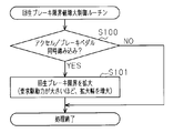
こうした摩擦ブレーキ装置11の温度上昇の抑制に係る制御は、図2に示す回生ブレーキ限界値増大制御ルーチンの処理を通じて行われる。同ルーチンの処理は、ハイブリッド車両の走行中、スキッドコントロールコンピューター14により、規定の制御周期毎に繰り返し実行される。
本ルーチンの処理が開始されると、まずステップS100において、アクセルペダル18とブレーキペダル9とが同時に踏み込まれているか否かが判定される。ここで、それらの同時踏み込みがなければ(S100:NO)、そのまま今回の本ルーチンの処理が終了され、そうでなければ(S100:YES)、ステップS101に処理が進められる。
ステップS101に処理が進められると、そのステップS101において、回生ブレーキ限界を拡大した上で、すなわち回生ブレーキ限界値を増大した上で、今回の本ルーチンの処理が終了される。そのため、このときには、回生発電を行うことで回生ブレーキ装置として機能するモーター3に発生させる制動力の上限値が大きくされる。
なお、このときの回生ブレーキ限界の拡大は、アクセル操作量に応じたハイブリッド車両の要求駆動力が大きいほど、その拡大幅が大きくなるように行われる。すなわち、図3に示すように、要求駆動力が大きく、車両の駆動力が大きくされるときほど、回生ブレーキ限界値が大きくされる。
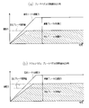
次に、こうした本実施の形態のブレーキ制御時の制御動作を説明する。
図4(a)に示すように、アクセルペダル18が踏み込まれず、ブレーキペダル9のみが単独で踏み込まれたときには、ブレーキペダル9の踏み込みが開始されてから暫くは、要求トータル制動力の増加に応じて、摩擦ブレーキ装置11の摩擦制動力、モーター3の回生発電による回生制動力が共に増加する。ただし、回生制動力が回生ブレーキ限界値に達すると、以後は、摩擦制動力のみが増加される。
一方、図4(b)に示すように、アクセルペダル18とブレーキペダル9とが同時に踏み込まれているときには、回生ブレーキ限界値が増加されるため、ブレーキペダル9の単独踏み込み時に比して、回生制動力はより大きい値まで増加される。そしてその分、摩擦制動力は小さくなる。そのため、摩擦ブレーキ装置11の発熱が抑えられ、その温度上昇が抑制されるようになる。
なお、制動中のハイブリッド車両の駆動力が大きくなると、摩擦ブレーキ装置11での摩擦による発熱が増える。その点、本実施の形態では、要求駆動力が大きいほど、回生ブレーキ限界値が大きくされ、摩擦制動力が小さくされる。そのため、要求駆動力が大きく、ハイブリッド車両の駆動力が大きくされるときにも、摩擦ブレーキ装置11の温度上昇が好適に抑えられるようになる。
以上説明した本実施の形態によれば、次の効果を奏することができる。
(1)本実施の形態では、運転者のアクセル操作とブレーキ操作とが同時に行われているときには、そうでないときに比して、回生ブレーキ限界値を大きくして回生ブレーキ装置の使用範囲を拡大している。回生ブレーキ装置の使用範囲が拡大されれば、その分、制動力全体に占める摩擦ブレーキ装置の分担割合は減る。そのため、運転者のアクセル操作とブレーキ操作とが同時に行われた状態が継続したときの摩擦ブレーキ装置の温度上昇が抑えられる。したがって、摩擦ブレーキ装置に設けられる冷却装置の構成の簡易化やその廃止が可能となり、摩擦ブレーキ装置の簡易化が可能となる。
(2)本実施の形態では、ハイブリッド車両の駆動力が大きいほど、回生ブレーキ装置の使用範囲の拡大幅を大きくしている。そのため、駆動力の増大により、摩擦ブレーキ装置11の発熱量が大きくなるときにも、摩擦ブレーキ装置11の温度上昇を好適に抑えることができる。
(第2の実施の形態)
続いて、本発明に係る車両の制御装置を具体化した第2の実施の形態を、図5及び図6を参照して説明する。なお、本実施の形態及び下記の第3の実施の形態において、上述の実施の形態と同様の構成については、同じ符号を付してその詳細な説明を省略する。
続いて、本発明に係る車両の制御装置を具体化した第2の実施の形態を、図5及び図6を参照して説明する。なお、本実施の形態及び下記の第3の実施の形態において、上述の実施の形態と同様の構成については、同じ符号を付してその詳細な説明を省略する。
第1の実施の形態では、運転者のアクセル操作とブレーキ操作とが同時に行われたときに、回生ブレーキ装置(モーター3)の使用範囲を拡大することで、摩擦ブレーキ装置11の発熱を抑え、その温度上昇を抑制するようにしていた。しかしながら、回生ブレーキ装置の使用範囲を拡大した状態が長期に亘って継続されると、回生発電を行うモーター3や同モーター3により発電された電力を蓄えるハイブリッド用バッテリー8の負荷が大きくなる。そこで、本実施の形態では、アクセル操作とブレーキ操作とが同時に行われている期間が長くなったときには、回生ブレーキ装置の使用範囲の拡大幅を小さくすることで、それらの負荷の増大を抑えている。
こうした本実施の形態でのアクセルペダル18及びブレーキペダル9の同時踏み込み時における回生ブレーキ装置の使用範囲の拡大は、図5に示す回生ブレーキ限界値増大制御ルーチンの処理を通じて行われる。同ルーチンの処理は、ハイブリッド車両の走行中、スキッドコントロールコンピューター14により、規定の制御周期毎に繰り返し実行される。
本ルーチンの処理が開始されると、まずステップS200において、アクセルペダル18とブレーキペダル9とが同時に踏み込まれているか否かが判定される。ここで、それらの同時踏み込みがなければ(S200:NO)、そのまま今回の本ルーチンの処理が終了され、そうでなければ(S200:YES)、ステップS201に処理が進められる。
ステップS201に処理が進められると、そのステップS201において、アクセルペダル18とブレーキペダル9との同時踏み込みが開始されてからの経過時間が規定の閾値以下であるか否かが判定される。この閾値には、モーター3やハイブリッド用バッテリー8の負荷の増大を許容される範囲内に留めつつ、回生ブレーキ装置の使用範囲を拡大した状態を継続可能な時間の最大値が設定されている。ここで、上記経過時間が閾値を超えていれば(S201:NO)、そのまま今回の本ルーチンの処理が終了される。
一方、上記経過時間が閾値以下であれば(S201:YES)、ステップS202に処理が進められる。そしてステップS202に処理が進められると、そのステップS202において、回生ブレーキ限界を拡大した上で、すなわち回生ブレーキ限界値を増大した上で、今回の本ルーチンの処理が終了される。
次に、こうした本実施の形態のアクセルペダル18、ブレーキペダル9の同時踏み込み時におけるブレーキ制御の制御動作を説明する。
図6に示すように、このときの回生ブレーキ装置の制動力は、要求トータル制動力の増加に応じ、アクセルペダル18及びブレーキペダル9の同時踏み込みに応じて増大された回生ブレーキ限界値まで増加される。ただし、アクセルペダル18及びブレーキペダル9の同時踏み込みの開始からの経過時間が閾値となる時刻t1となると、増大された回生ブレーキ限界値が本来の値に戻される。そのため、回生ブレーキ装置の制動力が低下され、モーター3やハイブリッド用バッテリー8の負荷が抑えられる。
以上説明した本実施の形態によれば、上記(1)に記載の効果に加え、更に次の効果を奏することができる。
(3)本実施の形態では、アクセル操作とブレーキ操作とが同時に行われている期間が長くなったときには、回生ブレーキ装置の使用範囲の拡大幅を小さくしている。そのため、回生ブレーキ装置の使用範囲の拡大の長期化によるモーター3やハイブリッド用バッテリー8の負荷の増加を好適に抑えることができる。
(第3の実施の形態)
続いて、本発明に係る車両の制御装置を具体化した第3の実施の形態を、図7を参照して説明する。
続いて、本発明に係る車両の制御装置を具体化した第3の実施の形態を、図7を参照して説明する。
ハイブリッド用バッテリー8の充電率や電圧、ハイブリッド用バッテリー8及びモーター3の温度が高いときには、それらの負荷がそもそも高い状態にあるため、回生ブレーキ装置の使用範囲の拡大に伴う負荷の増加に対するそれらの耐性は低くなる。そこで、本実施の形態では、そうした場合には、アクセルペダル18及びブレーキペダル9の同時踏み込みに応じた回生ブレーキ装置の使用範囲の拡大を行わないようにしている。
こうした本実施の形態でのアクセルペダル18及びブレーキペダル9の同時踏み込み時における回生ブレーキ装置の使用範囲の拡大は、図7に示す回生ブレーキ限界値増大制御ルーチンの処理を通じて行われる。同ルーチンの処理は、ハイブリッド車両の走行中、スキッドコントロールコンピューター14により、規定の制御周期毎に繰り返し実行される。
本ルーチンの処理が開始されると、まずステップS300において、アクセルペダル18とブレーキペダル9とが同時に踏み込まれているか否かが判定される。ここで、それらの同時踏み込みがなければ(S300:NO)、そのまま今回の本ルーチンの処理が終了され、そうでなければ(S300:YES)、ステップS301に処理が進められる。
ステップS301に処理が進められると、そのステップS301において、下記条件(A)~(D)がすべて成立しているか否かが判定される。
(A)ハイブリッド用バッテリー8の温度が規定の閾値以下であること。
(B)ハイブリッド用バッテリー8の電圧が規定の閾値以下であること。
(C)ハイブリッド用バッテリー8の充電率(State Of Charge:SOC)が規定の閾値以下であること。
(D)モーター3の温度が規定の閾値以下であること。
(A)ハイブリッド用バッテリー8の温度が規定の閾値以下であること。
(B)ハイブリッド用バッテリー8の電圧が規定の閾値以下であること。
(C)ハイブリッド用バッテリー8の充電率(State Of Charge:SOC)が規定の閾値以下であること。
(D)モーター3の温度が規定の閾値以下であること。
ここで上記条件(A)~(D)のいずれか一つ以上が不成立であれば(S301:NO)、そのまま今回の本ルーチンの処理が終了される。一方、上記条件(A)~(D)がすべて成立していれば(S301:YES)、ステップS302に処理が進められる。そしてステップS302に処理が進められると、そのステップS302において、回生ブレーキ限界を拡大した上で、すなわち回生ブレーキ限界値を増大した上で、今回の本ルーチンの処理が終了される。
以上説明した本実施の形態によれば、上記(1)に記載の効果に加え、更に次の効果を奏することができる。
(4)本実施の形態では、ハイブリッド用バッテリー8の充電率(SOC)、電圧、温度、及びモーター3の温度が高いときには、アクセルペダル18及びブレーキペダル9の同時踏み込みに応じた回生ブレーキ装置の使用範囲の拡大を行わないようにしている。そのため、ハイブリッド用バッテリー8やモーター3の負荷がそもそも高い状態でそれらの負荷が更に増加される事態となることを回避することができる。
以上の各実施の形態は、次のように変更して実施することもできる。
・第1の実施の形態では、ハイブリッド車両の駆動力が大きいときほど、回生ブレーキ装置の使用範囲の拡大幅を大きくしていたが、ハイブリッド車両の駆動力の増加による摩擦ブレーキ装置11の発熱量の増加が十分に小さいのであれば、ハイブリッド車両の駆動力に拘わらず、回生ブレーキ装置の使用範囲の拡大幅を一定としても良い。
・第2の実施の形態では、アクセルペダル18及びブレーキペダル9の同時踏み込みの開始からの経過時間が長くなると回生ブレーキ装置の使用範囲の拡大を中止していたが、その拡大を完全には中止せず、その拡大幅を小さくするだけでも、摩擦ブレーキ装置11の温度上昇を好適に抑えることは可能である。
・第2の実施の形態では、アクセルペダル18及びブレーキペダル9の同時踏み込みの開始からの経過時間が閾値となった時点で一度だけ回生ブレーキ装置の使用範囲の拡大幅を小さくしていたが、経過時間に応じて回生ブレーキ装置の使用範囲の拡大幅を段階的に小さくしたり、漸減したりしても良い。
・第3の実施の形態では、上記条件(A)~(D)がすべての成立するときにのみ、アクセルペダル18及びブレーキペダル9の同時踏み込みに応じた回生ブレーキ装置の使用範囲の拡大を行うようにしていたが、それら条件(A)~(D)の一つ以上を割愛するようにしても良い。例えばモーター3の温度が多少高くても、回生ブレーキ装置の使用範囲の拡大に伴う負荷の増加にモーター3が十分に耐えられる場合には、上記条件(D)を割愛し、上記条件(A)~(C)のすべての成立に応じて、アクセルペダル18及びブレーキペダル9の同時踏み込みに応じた回生ブレーキ装置の使用範囲の拡大を行うようにしても良い。
・摩擦ブレーキ装置11の発熱量は、摩擦制動力の大きさによっても変化するため、アクセルペダル18及びブレーキペダル9の同時踏み込みに応じた回生ブレーキ装置の使用範囲の拡大幅を、摩擦制動力の大きさに応じて可変とするようにしても良い。
・摩擦ブレーキ装置11の発熱量は、車速によっても変化するため、アクセルペダル18及びブレーキペダル9の同時踏み込みに応じた回生ブレーキ装置の使用範囲の拡大幅を、車速に応じて可変とするようにしても良い。
・摩擦ブレーキ装置11の温度がそもそも高いときには、回生ブレーキ装置の使用範囲の拡大に伴う発熱量の増加により摩擦ブレーキ装置11の温度がより高くなるため、アクセルペダル18及びブレーキペダル9の同時踏み込みに応じた回生ブレーキ装置の使用範囲の拡大幅を、摩擦ブレーキ装置11の温度に応じて可変とするようにしても良い。なお、摩擦ブレーキ装置11の温度は、直接検出する他、ブレーキ油の温度やそれまでの摩擦ブレーキ装置11の使用状況、大気温などから推定することも可能である。
・上記実施の形態では、回生ブレーキ限界値を、すなわち回生ブレーキ装置に発生させる制動力(回生制動力)の上限値を大きくすることで、回生ブレーキ装置の使用範囲を拡大するようにしていたが、それ以外の態様で回生ブレーキ装置の使用範囲を拡大するようにしても良い。例えば、回生ブレーキ装置が回生制動力を発生した状態を継続する時間に制限が設けられている場合には、その時間の制限を緩和して、回生制動力をより長い時間発生させられるようにすることでも、回生ブレーキ装置の使用範囲を拡大することができる。いずれにせよ、回生ブレーキ装置の使用範囲が拡大されれば、その分、制動力全体に占める摩擦ブレーキ装置11の分担割合が減じられて、摩擦ブレーキ装置11の温度上昇が抑えられるようになる。
・上記実施の形態では、本発明に係る車両の制御装置をハイブリッド車両に適用した場合を説明したが、本発明は、摩擦ブレーキ装置と回生ブレーキ装置とを備える車両であれば、ハイブリッド車両以外の車両にも、上記実施の形態と同様あるいはそれに準じた態様で適用することができる。
・上記実施の形態では、運転者のアクセル操作とブレーキ操作とが同時に行われたときに車両の駆動力を低下させるブレーキオーバーライドシステムを採用する車両に本発明を適用した場合を説明した。尤も、ブレーキオーバーライドシステムを未採用の車両でも、アクセル操作とブレーキ操作とが同時に行われた状態が長時間継続すれば、やはり摩擦ブレーキ装置11の温度は上昇するようになる。そのため、ブレーキオーバーライドシステムを未採用の車両においても、本発明の制御装置の適用は、同様に有効である。
1…エンジン、2…ジェネレーター、3…モーター、4…動力分割機構、5…減速機構、6…駆動輪、7…パワーコントロールユニット、8…ハイブリッド用バッテリー、9…ブレーキペダル、10…マスターシリンダー、11…摩擦ブレーキ装置、12…ブレーキアクチュエーター、13…ストロークシミュレーター、14…スキッドコントロールコンピューター、15…ブレーキペダルストロークセンサー、16…車輪速センサー、17…パワーマネジメントコントロールコンピューター、18…アクセルペダル、19…アクセルペダルストロークセンサー。
Claims (9)
- 摩擦ブレーキ装置と回生ブレーキ装置とを備える車両の制御装置において、
運転者のアクセル操作とブレーキ操作とが同時に行われているときには、そうでないときに比して、前記回生ブレーキ装置の使用範囲が拡大される
ことを特徴とする車両の制御装置。 - 当該車両の駆動力が大きいほど、前記回生ブレーキ装置の使用範囲の拡大幅が大きくなる
請求項1に記載の車両の制御装置。 - 前記アクセル操作とブレーキ操作とが同時に行われている期間が長くなると、前記回生ブレーキ装置の使用範囲の拡大幅が小さくなる
請求項2に記載の車両の制御装置。 - 前記回生ブレーキ装置によって発電された電力を蓄えるバッテリーの充電率が閾値以上のときには、そうでないときに比して前記回生ブレーキ装置の使用範囲の拡大幅が小さくなる
請求項1~3のいずれか1項に記載の車両の制御装置。 - 前記回生ブレーキ装置によって発電された電力を蓄えるバッテリーの電圧が閾値以上のときには、そうでないときに比して前記回生ブレーキ装置の使用範囲の拡大幅が小さくなる
請求項1~4のいずれか1項に記載の車両の制御装置。 - 前記回生ブレーキ装置によって発電された電力を蓄えるバッテリーの温度が閾値以上のときには、そうでないときに比して前記回生ブレーキ装置の使用範囲の拡大幅が小さくなる
請求項1~5のいずれか1項に記載の車両の制御装置。 - 前記回生ブレーキ装置は回生発電を行う発電機を含み、同発電機の温度が閾値以上のときには、そうでないときに比して前記回生ブレーキ装置の使用範囲の拡大幅が小さくなる
請求項1~6のいずれか1項に記載の車両の制御装置。 - 運転者のアクセル操作とブレーキ操作とが同時に行われているときに該車両の駆動源の出力が低下される
請求項1~7のいずれか1項に記載の車両の制御装置。 - 前記使用範囲の拡大は、前記回生ブレーキ装置に発生させる制動力の上限値を大きくすることで行われる
請求項1~8のいずれか1項に記載の車両の制御装置。
Priority Applications (5)
| Application Number | Priority Date | Filing Date | Title |
|---|---|---|---|
| JP2013548041A JP5790782B2 (ja) | 2011-12-09 | 2011-12-09 | 車両の制御装置 |
| CN201180075295.3A CN103974866A (zh) | 2011-12-09 | 2011-12-09 | 车辆的控制装置 |
| EP11877041.1A EP2789516B1 (en) | 2011-12-09 | 2011-12-09 | Vehicle control device |
| PCT/JP2011/078589 WO2013084358A1 (ja) | 2011-12-09 | 2011-12-09 | 車両の制御装置 |
| US14/361,002 US9902390B2 (en) | 2011-12-09 | 2011-12-09 | Vehicle control device |
Applications Claiming Priority (1)
| Application Number | Priority Date | Filing Date | Title |
|---|---|---|---|
| PCT/JP2011/078589 WO2013084358A1 (ja) | 2011-12-09 | 2011-12-09 | 車両の制御装置 |
Publications (1)
| Publication Number | Publication Date |
|---|---|
| WO2013084358A1 true WO2013084358A1 (ja) | 2013-06-13 |
Family
ID=48573756
Family Applications (1)
| Application Number | Title | Priority Date | Filing Date |
|---|---|---|---|
| PCT/JP2011/078589 WO2013084358A1 (ja) | 2011-12-09 | 2011-12-09 | 車両の制御装置 |
Country Status (5)
| Country | Link |
|---|---|
| US (1) | US9902390B2 (ja) |
| EP (1) | EP2789516B1 (ja) |
| JP (1) | JP5790782B2 (ja) |
| CN (1) | CN103974866A (ja) |
| WO (1) | WO2013084358A1 (ja) |
Cited By (2)
| Publication number | Priority date | Publication date | Assignee | Title |
|---|---|---|---|---|
| JP2015139350A (ja) * | 2014-01-24 | 2015-07-30 | 株式会社ミツバ | モータ回生制御装置およびモータ回生制御方法 |
| CN112523875A (zh) * | 2020-12-01 | 2021-03-19 | 广西玉柴机器股份有限公司 | 一种船用发动机越控功能的控制方法 |
Families Citing this family (10)
| Publication number | Priority date | Publication date | Assignee | Title |
|---|---|---|---|---|
| DE102013205314B4 (de) * | 2013-03-26 | 2016-09-29 | Continental Automotive Gmbh | Verfahren zum Betreiben einer Rekuperationsbremseinrichtung eines Kraftfahrzeugs und Rekuperationsbremseinrichtung für ein Kraftfahrzeug |
| US9545849B2 (en) * | 2014-09-19 | 2017-01-17 | Ford Global Technologies, Llc | Vehicle system and method for adapting lift pedal regeneration |
| CN106184193B (zh) * | 2015-04-29 | 2018-12-21 | 比亚迪股份有限公司 | 车辆行驶的控制方法及控制系统及车辆 |
| JP6657839B2 (ja) * | 2015-11-20 | 2020-03-04 | いすゞ自動車株式会社 | ハイブリッド車両及びその制御方法 |
| KR102298961B1 (ko) * | 2017-03-03 | 2021-09-06 | 현대자동차주식회사 | 친환경자동차의 회생제동 제어 장치 및 방법 |
| CN108297860B (zh) * | 2018-03-27 | 2020-01-03 | 北京长安汽车工程技术研究有限责任公司 | 一种油门踏板开度解析控制方法、装置及系统 |
| JP2019188962A (ja) * | 2018-04-23 | 2019-10-31 | 本田技研工業株式会社 | 車両の制御装置 |
| KR102537878B1 (ko) * | 2018-11-01 | 2023-05-31 | 현대자동차주식회사 | 하이브리드 자동차 및 그를 위한 주행 제어 방법 |
| CN111422193B (zh) * | 2019-07-01 | 2021-11-26 | 长城汽车股份有限公司 | 一种制动控制方法、系统及车辆 |
| DE102022114926A1 (de) * | 2022-06-14 | 2023-12-14 | Bayerische Motoren Werke Aktiengesellschaft | Vorrichtung und ein Verfahren zur Benachrichtigung eines Fahrers eines Kraftfahrzeugs mit wenigstens einem Elektromotor zum Antreiben und Verzögern einer Achse des Kraftfahrzeugs |
Citations (3)
| Publication number | Priority date | Publication date | Assignee | Title |
|---|---|---|---|---|
| JPH0984206A (ja) * | 1995-09-08 | 1997-03-28 | Mitsubishi Motors Corp | 電気自動車の走行制御装置 |
| JP2008154324A (ja) * | 2006-12-15 | 2008-07-03 | Tcm Corp | 産業用電気駆動車両の制動装置 |
| JP2010038051A (ja) | 2008-08-06 | 2010-02-18 | Denso Corp | 車載動力発生装置のトルク制御装置 |
Family Cites Families (21)
| Publication number | Priority date | Publication date | Assignee | Title |
|---|---|---|---|---|
| US5905349A (en) * | 1998-04-23 | 1999-05-18 | Ford Motor Company | Method of controlling electric motor torque in an electric vehicle |
| GB9818960D0 (en) * | 1998-09-02 | 1998-10-21 | Rover Group | A vehicle |
| US6278916B1 (en) * | 2000-05-09 | 2001-08-21 | Ford Global Technologies, Inc. | Torque control strategy for management of creep and grade hold torque in a wheeled vehicle whose powertrain includes a rotary electric machine |
| US20050151420A1 (en) * | 2001-05-07 | 2005-07-14 | Dale Crombez | Hybrid electric vehicle powertrain with regenerative braking |
| JP3676336B2 (ja) * | 2002-10-02 | 2005-07-27 | 本田技研工業株式会社 | ハイブリッド車両の出力制御装置 |
| JP4146784B2 (ja) * | 2003-11-18 | 2008-09-10 | 富士重工業株式会社 | ハイブリッド車両の駆動力制御装置 |
| JP2007030631A (ja) * | 2005-07-25 | 2007-02-08 | Advics:Kk | 車両用ブレーキ制御装置 |
| JP4188348B2 (ja) * | 2005-08-10 | 2008-11-26 | 株式会社日立製作所 | 電動車両の走行制御装置および電動走行制御システム |
| US8366210B2 (en) * | 2006-04-03 | 2013-02-05 | Advics Co., Ltd. | Braking apparatus for vehicle |
| JP2008222121A (ja) * | 2007-03-14 | 2008-09-25 | Toyota Motor Corp | 車輌の制動装置 |
| US20100217491A1 (en) * | 2007-07-02 | 2010-08-26 | Equos Research Co., Ltd. | Camber angle controlling device |
| US8155814B2 (en) * | 2007-11-03 | 2012-04-10 | GM Global Technology Operations LLC | Method of operating a vehicle utilizing regenerative braking |
| US8038573B2 (en) * | 2008-04-17 | 2011-10-18 | Bayerische Motoren Werke Aktiengesellschaft | Power development for rapid start in full-hybrid drives with optimized traction control |
| JP4386138B1 (ja) * | 2008-06-27 | 2009-12-16 | トヨタ自動車株式会社 | ハイブリッド車両の制御装置および制御方法 |
| US8359149B2 (en) * | 2009-02-03 | 2013-01-22 | GM Global Technology Operations LLC | Method for integrating multiple feature adaptive cruise control |
| DE102010027348A1 (de) * | 2010-02-16 | 2011-08-18 | Magna Steyr Fahrzeugtechnik Ag & Co Kg | Verfahren und Steuerung/Regelung zum Abbremsen eines Fahrzeuges sowie Fahrzeug |
| JP5062369B2 (ja) * | 2010-03-29 | 2012-10-31 | トヨタ自動車株式会社 | 車両の制御装置 |
| US8554419B2 (en) * | 2010-05-28 | 2013-10-08 | Ford Global Technologies, Llc | Control of a vehicle powertrain in response to brake pedal input |
| US20120138395A1 (en) * | 2010-12-01 | 2012-06-07 | Aptera Motors, Inc. | Automotive vehicle regenerative braking control system |
| JP5832868B2 (ja) * | 2011-11-22 | 2015-12-16 | Ntn株式会社 | 電気自動車 |
| WO2014155720A1 (ja) * | 2013-03-29 | 2014-10-02 | 三菱電機株式会社 | 電気車制御装置および電気車のブレーキ制御方法 |
-
2011
- 2011-12-09 EP EP11877041.1A patent/EP2789516B1/en active Active
- 2011-12-09 WO PCT/JP2011/078589 patent/WO2013084358A1/ja active Application Filing
- 2011-12-09 CN CN201180075295.3A patent/CN103974866A/zh active Pending
- 2011-12-09 JP JP2013548041A patent/JP5790782B2/ja active Active
- 2011-12-09 US US14/361,002 patent/US9902390B2/en active Active
Patent Citations (3)
| Publication number | Priority date | Publication date | Assignee | Title |
|---|---|---|---|---|
| JPH0984206A (ja) * | 1995-09-08 | 1997-03-28 | Mitsubishi Motors Corp | 電気自動車の走行制御装置 |
| JP2008154324A (ja) * | 2006-12-15 | 2008-07-03 | Tcm Corp | 産業用電気駆動車両の制動装置 |
| JP2010038051A (ja) | 2008-08-06 | 2010-02-18 | Denso Corp | 車載動力発生装置のトルク制御装置 |
Cited By (3)
| Publication number | Priority date | Publication date | Assignee | Title |
|---|---|---|---|---|
| JP2015139350A (ja) * | 2014-01-24 | 2015-07-30 | 株式会社ミツバ | モータ回生制御装置およびモータ回生制御方法 |
| CN112523875A (zh) * | 2020-12-01 | 2021-03-19 | 广西玉柴机器股份有限公司 | 一种船用发动机越控功能的控制方法 |
| CN112523875B (zh) * | 2020-12-01 | 2022-08-12 | 广西玉柴机器股份有限公司 | 一种船用发动机越控功能的控制方法 |
Also Published As
| Publication number | Publication date |
|---|---|
| US9902390B2 (en) | 2018-02-27 |
| EP2789516A1 (en) | 2014-10-15 |
| JP5790782B2 (ja) | 2015-10-07 |
| EP2789516A4 (en) | 2016-03-09 |
| JPWO2013084358A1 (ja) | 2015-04-27 |
| EP2789516B1 (en) | 2020-09-16 |
| CN103974866A (zh) | 2014-08-06 |
| US20140330472A1 (en) | 2014-11-06 |
Similar Documents
| Publication | Publication Date | Title |
|---|---|---|
| JP5790782B2 (ja) | 車両の制御装置 | |
| JP5736673B2 (ja) | 複合ブレーキの制動力協調制御装置 | |
| JP5943011B2 (ja) | ハイブリッド車両 | |
| JP5262777B2 (ja) | 車両用制動制御装置 | |
| JP5725037B2 (ja) | 車両および車両用制御方法 | |
| JP2013258905A (ja) | 少なくとも1つの電気モータを含む車両の回生制動制御方法 | |
| JP2013121231A (ja) | 電動車両の制御装置 | |
| JP2008265397A (ja) | 車両の制動制御装置 | |
| JP6213497B2 (ja) | ハイブリッド車両 | |
| WO2013084357A1 (ja) | ハイブリッド車両の制御装置 | |
| KR102353346B1 (ko) | 차량의 제동 제어 장치 및 방법 | |
| JP5729475B2 (ja) | 車両および車両の制御方法 | |
| JP2006197756A (ja) | 車両の回生制動制御装置 | |
| JP5348226B2 (ja) | 車両の制動制御装置 | |
| JP5765419B2 (ja) | 車両および車両用制御方法 | |
| JP2006254553A (ja) | 車両の制御装置 | |
| JP6120010B2 (ja) | 車両 | |
| JP2015205547A (ja) | ハイブリッド自動車の制御装置 | |
| JP6734735B2 (ja) | 車両用制御装置 | |
| JP6291460B2 (ja) | 電動車両 | |
| KR102354195B1 (ko) | Phev 청소차 주행 제어장치 | |
| JP2008013061A (ja) | 油圧制動力の低下速度を考慮に入れた油圧/回生制動組合せ車輌 | |
| JP2021040377A (ja) | 協調ブレーキシステム | |
| JP2015104149A (ja) | 車両 | |
| KR20150108512A (ko) | 마일드 하이브리드 장치 및 이를 이용한 회생 효율 증대 방법 |
Legal Events
| Date | Code | Title | Description |
|---|---|---|---|
| 121 | Ep: the epo has been informed by wipo that ep was designated in this application |
Ref document number: 11877041 Country of ref document: EP Kind code of ref document: A1 |
|
| DPE1 | Request for preliminary examination filed after expiration of 19th month from priority date (pct application filed from 20040101) | ||
| ENP | Entry into the national phase |
Ref document number: 2013548041 Country of ref document: JP Kind code of ref document: A |
|
| WWE | Wipo information: entry into national phase |
Ref document number: 14361002 Country of ref document: US |
|
| NENP | Non-entry into the national phase |
Ref country code: DE |