WO2013077123A1 - 車体構造 - Google Patents
車体構造 Download PDFInfo
- Publication number
- WO2013077123A1 WO2013077123A1 PCT/JP2012/077101 JP2012077101W WO2013077123A1 WO 2013077123 A1 WO2013077123 A1 WO 2013077123A1 JP 2012077101 W JP2012077101 W JP 2012077101W WO 2013077123 A1 WO2013077123 A1 WO 2013077123A1
- Authority
- WO
- WIPO (PCT)
- Prior art keywords
- vehicle body
- torsion beam
- floor
- inclined floor
- body structure
- Prior art date
- Legal status (The legal status is an assumption and is not a legal conclusion. Google has not performed a legal analysis and makes no representation as to the accuracy of the status listed.)
- Ceased
Links
Images

Classifications
-
- B—PERFORMING OPERATIONS; TRANSPORTING
- B62—LAND VEHICLES FOR TRAVELLING OTHERWISE THAN ON RAILS
- B62D—MOTOR VEHICLES; TRAILERS
- B62D25/00—Superstructure or monocoque structure sub-units; Parts or details thereof not otherwise provided for
- B62D25/08—Front or rear portions
- B62D25/087—Luggage compartments
Definitions
- the present invention relates to an improvement in a vehicle body structure capable of loading a load on the rear part of a vehicle.
- Patent Document 1 Conventionally, for the purpose of loading a load such as a wheelchair, a vehicle body having a slope at the rear of the vehicle has been produced (see, for example, Patent Document 1).
- a fuel tank is disposed under the rear floor. For this reason, the rear floor cannot be set low.
- the kick-up portion of the side frame cannot be brought close to the slope.
- the angle of the slope is limited, which is disadvantageous in increasing the ease of getting on and off the rear seat, and the length of the slope must be shortened.
- the rear wheel suspension of a four-wheel drive vehicle capable of loading a wheelchair as disclosed in Patent Document 1 is generally provided with a rear differential as a rear wheel axle in order to avoid interference with the fuel tank and the slope.
- a so-called axle suspension type that swings up and down is adopted, and when this axle suspension type suspension is adopted, since the rear differential swings up and down, further consideration is necessary so as not to interfere with the slope, Low degree of freedom in design.
- An object of the present invention is to provide a vehicle body structure that can reduce the height of an inclined floor and a floor panel positioned in front of the inclined floor, and can increase the degree of freedom in designing a rear suspension and a rear wheel drive device. There is.
- the left and right side frames have a kick-up portion formed upward from a lower end side of a door opening formed on a side surface of the vehicle body, and the kick-up.
- An inclined floor formed between the left and right side frames from the upper end side of the vehicle body toward the rear opening of the rear end surface of the vehicle body.
- a torsion beam type rear suspension is provided below the front end of the inclined floor.
- a vehicle body structure in which a torsion beam is arranged is provided.
- the torsion beam has a first space having a first ground height below the torsion beam, and is defined by a lower surface of the inclined floor behind the torsion beam.
- a second space having a ground clearance is formed, and a floor cross member extending in the vehicle width direction is disposed under the front end portion of the inclined floor. The floor cross member and the torsion beam are shifted from each other in the vehicle longitudinal direction. Has been placed.
- an energy source is arranged under a seat positioned in front of the kick-up portion.
- an energy source is arranged under a seat positioned in front of the kick-up portion.
- the torsion beam is formed in a U-shaped cross section that opens frontward and upward, and the vehicle width center portion is formed narrower than both ends in the vehicle width direction.
- the vehicle body structure is located below the torsion beam and extends in the longitudinal direction of the vehicle body, and is disposed behind the torsion beam, from the propeller shaft (52).
- a differential for transmitting the input to the rear axle, and the torsion beam, the differential, and the rear opening are arranged so as to partially overlap each other in the longitudinal direction of the vehicle body.
- the differential is supported by a support portion, and the support portion is provided from the bottom surface side of the inclined floor to the rear opening.
- a cross member parallel to the rear axle is joined to the left and right side frames so as to surround a vehicle body side of the inclined floor.
- the torsion beam by arranging the torsion beam below the front end of the inclined floor inclined backward and downward, that is, near the top of the inclined floor, the torsion beam is brought close to the rear of the floor panel defined by the kick-up portion.
- the interference between the inclined floor and the torsion beam suspension can be minimized.
- the starting point of the top of the inclined floor can be set forward and downward. Accordingly, the height of the inclined floor and the floor panel positioned in front of the inclined floor can be reduced, and the degree of freedom in designing the rear suspension and the rear wheel drive device can be increased.
- the floor cross member and the torsion beam are arranged so as to be shifted from each other in the longitudinal direction of the vehicle body, they do not overlap vertically. For this reason, the axial center of the torsion beam can be arranged further upward, and the first space below the torsion beam can be set larger than the case where the first space overlaps vertically.
- additional structural components such as a propeller shaft for driving the rear wheels and an exhaust pipe for the engine can be arranged below the torsion beam. Therefore, the large diameter part of these structural components can be arrange
- the height of the top of the inclined floor with respect to the torsion beam can be kept relatively small, the inclination of the inclined floor can be relaxed.
- an energy source for example, a fuel tank or a battery
- the energy source does not interfere with the inclined floor, and the distance in the front-rear direction between the inclined floor and the left and right kick-up portions can be minimized. Therefore, the position of the top (starting point) of the front end of the inclined floor can be set more forward of the vehicle body without reducing the size and capacity of the energy source.
- the torsion beam is formed in a U-shaped cross section that opens frontward and upward, and the vehicle width center portion is formed narrower than both ends in the vehicle width direction.
- a so-called H beam in which left and right trailing arms are provided at both ends of the torsion beam in the vehicle width direction is employed.
- the front end portions (swing front end portions) of the left and right trailing arms are mounted on the vehicle body so as to be able to swing up and down.
- the swing center of the left and right swing front end portions are arranged in the front upper direction, thereby ensuring the stroke amount of the H beam, the vibration damping characteristic and the steering stability characteristic.
- the swing region of the torsion beam can be arranged close to the front end of the inclined floor. For this reason, the space below the inclined floor can be utilized efficiently.
- the torsion beam, the differential, and the rear opening are arranged so that each part thereof overlaps in the vehicle body longitudinal direction. For this reason, while reducing the height of a floor panel, the height of the top part of an inclination floor can be suppressed, and the inclination of an inclination floor can be made loose. And the load can be easily taken in and out by setting the height of the rear end of the inclined floor to be lower than the height of the differential.
- the support portion for supporting the differential is provided from the bottom surface side of the inclined floor to the rear opening. For this reason, it is possible to compensate for the rigidity reduction in the vicinity of the rear opening (including the peripheral edge of the rear opening) accompanying the reduction in the height of the floor panel (lowering the floor), and to increase the rigidity in the vicinity of the rear opening.
- the differential can be supported by the support portion below the inclined floor.
- the rigidity of the inclined floor can be increased by reinforcing the bottom surface of the inclined floor with the support portion. That is, the load bearing performance of the inclined floor with respect to the load loaded on the inclined floor is enhanced.
- a plurality of cross members parallel to the rear axle are joined to the left and right side frames so as to surround the lower surface of the inclined floor.
- the inclined floor is surrounded by the left and right side frames and a plurality of cross members spanned between the left and right side frames, thereby increasing rigidity.
- FIG. 2 is a vehicle width central sectional view of a rear portion of the vehicle body shown in FIG. 1.
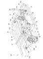
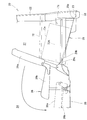
- FIG. 3 is a perspective view of a state in which a torsion beam type rear suspension and a differential are provided at the rear part of the vehicle body shown in FIG. 2 as viewed from the upper left.
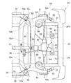
- FIG. 4 is a bottom view in which a torsion beam type rear suspension and a differential are provided at the rear part of the vehicle body shown in FIG. 3.
- FIG. 4 is a vehicle width central sectional view in which a torsion beam type rear suspension and a differential are provided at the rear of the vehicle body shown in FIG. 3.
- FIG. 3 is a vehicle width central sectional view of which a torsion beam type rear suspension and a differential are provided at the rear of the vehicle body shown in FIG. 3.
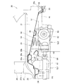
- FIG. 3 is a side view in which a luggage space and a rear seat are provided at the rear of the vehicle body shown in FIG. 2.
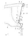
- FIG. 6 is a side view in which a torsion beam type rear suspension and a differential are provided at the rear part of the vehicle body shown in FIG. 5.
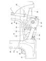
- FIG. 5 is a perspective view of a state in which a torsion beam type rear suspension and a differential are provided at the rear part of the vehicle body shown in FIG. 4 as viewed from the lower left.
- the vehicle 10 is an FR vehicle that has the engine 11 mounted thereon and drives the rear wheel 12, or an FF vehicle that has the engine 11 mounted on the front, or a 4WD vehicle that drives four front and rear wheels.
- the vehicle is a five-door vehicle having left and right front doors, left and right rear doors, and a tailgate 22 of a rear end surface 21 (rear panel 21) of the vehicle body 20.
- a rear opening 23 formed in the rear end face 21 is opened and closed by a tailgate 22.
- the vehicle 10 includes a front seat 25 and a rear seat 26 in a passenger compartment 24, and a luggage compartment space 27 in which a load can be loaded behind the rear seat 26.
- the floor of the passenger compartment 24 includes a substantially horizontal floor panel 28 on which the front seat 25 and the rear seat 26 are arranged, and an inclined floor 29 formed integrally with the rear portion of the floor panel 28.
- the inclined floor 29 is a member that becomes a floor of the luggage space 27 and is inclined downward. Loads such as wheelchairs and bicycles can be taken in and out of the luggage space 27 from the rear opening 23.
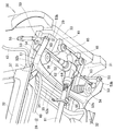
- the rear half of the vehicle body 20 is located at the rear of the vehicle body and extends to the left and right rear side frames 31, 31 and kicks up the left and right rear side frames 31, 31.
- Left and right side sills 32, 32 extending continuously forward from the portions 37, 37, the front cross member 34, the front floor cross member 35, the rear floor cross member 36, the floor panel 28, and the inclined floor 29 Including.
- the left and right side frames 31, 31 have left and right kick-up portions 37, 37.
- the left and right kick-up portions 37, 37 merge with the left and right side sills 32, 32 and upward from the rear end and lower end side of the left and right door openings 38, 38 (FIG. 2) formed on the side surface of the vehicle body 20.
- the left and right side frames 31 and 31 are integrally formed.
- the left and right rear pillars 39, 39 stand up from the upper ends of the left and right kick-up portions 37, 37, and the floor panel 28 is formed to rise upward along the kick-up portions 37, 37.
- the left and right door openings 38 are opened and closed by left and right rear doors (not shown).
- the rear seat 26 is located substantially in the vehicle width direction with respect to the left and right kick-up portions 37, 37.
- the rear seat 26 is located immediately in front of the inclined floor 29, and as shown by an imaginary line, the seat back 26a can be tilted forward and the seat cushion 26b can be moved forward and downward. Down structure.
- An energy source 13 such as a fuel tank or a battery is disposed under the seat 25 (FIG. 1) positioned in front of the left and right kick-up portions 37, 37.
- the rear cross member 33 is disposed at the lower edge of the rear opening 23 and is spanned between the rear ends 31a, 31a of the left and right side frames 31, 31.
- the rear cross member 33 supports the rear end 29 a of the inclined floor 29 by being positioned on the lower surface of the rear end 29 a of the inclined floor 29.
- the front cross member 34 is stretched between the front ends 31b and 31b of the kick-up portions of the left and right side frames 31 and 31.
- the front cross member 34 supports the rear portion of the floor panel 28 by being positioned on the lower surface of the rear portion of the floor panel 28.
- the front floor cross member 35 and the rear floor cross member 36 are disposed between the rear cross member 33 and the front cross member 34 and are spanned between the left and right side frames 31 and 31. That is, the front floor cross member 35 is positioned on the lower surface of the front end 29b of the inclined floor 29 and extends in the vehicle width direction, thereby supporting the front end 29b of the inclined floor 29.
- the front floor cross member 35 is set at a higher position than the front cross member 34.
- the rear floor cross member 36 is positioned on the lower surface of the intermediate portion of the inclined floor 29 and extends in the vehicle width direction, thereby supporting the intermediate portion of the inclined floor 29.
- the rear floor cross member 36 is set at a position lower than the front floor cross member 35 and higher than the front cross member 34.
- a mounting seat for the rear seat 26 (FIG. 1) is formed on the front cross member 34 and the front floor cross member 35.
- the inclined floor 29 is inclined between the left and right side frames 31 and 31 from the upper ends 37a and 37a of the left and right kick-up portions 37 and 37 toward the rear opening 23 of the rear end surface 21 of the vehicle body 20 and rearward and downward.
- the inclined floor 29 may be any as long as it forms an inclined surface having a certain degree of angle with respect to the left and right side frames 31, 31 that are generally horizontal.
- the inclined floor 29 is configured by a flat plate that is inclined with a certain degree of continuity from the upper ends 37a, 37a of the left and right kick-up portions 37, 37 to the rear opening 23.
- the front end 29b of the inclined floor 29 inclined downward and rearward, that is, the top portion 29c of the inclined floor 29 is supported by the front floor cross member 35.
- a front end 29b of the inclined floor 29 and a rear end 28a of the floor panel 28 are overlapped on the left and right side frames 31, 31 and the front floor cross member 35, and are joined together by welding or the like.
- the rear cross member 33 and the front floor cross member 35 are arranged on the lower surface of the inclined floor 29 so as to surround the inclined floor 29 and are joined to the left and right side frames 31, 31. ing. That is, the inclined floor 29 is surrounded by an imaginary line frame Sp ⁇ b> 3 formed by the left and right side frames 31, 31, the rear cross member 33, and the front floor cross member 35.
- left and right support portions 41, 41 are spanned between the rear cross member 33 and the rear floor cross member 36. That is, the left and right support portions 41, 41 extend in the longitudinal direction of the vehicle body, and both ends thereof are joined to the rear cross member 33 and the rear floor cross member 36, thereby extending from the bottom surface side of the inclined floor 29 to the rear opening 23. Is provided.
- a torsion beam type rear suspension 50 is disposed below the inclined floor 29.
- a beam body 51 of the torsion beam type rear suspension 50 includes a torsion beam 52 extending in the vehicle width direction and left and right trailing arms 53 and 53 integrally provided at both ends of the torsion beam 52 in the vehicle width direction. This is a so-called H beam formed in a substantially H shape.
- the torsion beam type rear suspension 50 includes a torsion beam 52 extending in the vehicle width direction, left and right trailing arms 53, 53 integrally provided at both ends of the torsion beam 52 in the vehicle width direction, and the left and right trailing arms 53,
- the left and right springs 54 and 54 for buffering supported by 53 and left and right dampers 55 and 55 are provided.
- the torsion beam 52 is disposed slightly behind the front floor cross member 35.
- the front end portions 53a and 53a (left and right swing front end portions 53a and 53a) of the left and right trailing arms 53 and 53 are mounted on the vehicle body 20 so as to be able to swing up and down.
- Left and right rear axles 63 and 63 for left and right rear wheels 12 and 12 (FIG. 1) are rotatably supported on the rear end portions 53b and 53b of the left and right trailing arms 53 and 53, respectively. Therefore, the rear suspension 50 and the left and right rear axles 63 and 63 can swing up and down with reference to the swing centers CL and CL (FIG. 4) of the left and right front end portions 53a and 53a.
- all the cross members 33 to 36 are substantially parallel to the left and right rear axles 63, 63.
- the torsion beam 52 is formed in a U-shaped cross-section (FIG. 5) that opens forward and upward, and as shown in FIG. 4, the vehicle width center portion 52a is narrower than the vehicle width direction both ends 52b and 52b. Has been.
- the distance between the vehicle width direction ends 52b and 52b of the torsion beam 52 with respect to the front floor cross member 35 and the inclined floor 29 is larger than the distance between the front floor cross member 35 and the inclined floor 29 with respect to the vehicle width central portion 52a. As shown in FIGS. 2, 7, and 8, by using this large distance, there is no fuel between the front floor cross member 35 and the inclined floor 29 and the vehicle width direction end portion 52 b of the torsion beam 52.
- a filler pipe 43 for supplying fuel to the tank is provided.
- a propeller shaft 61 and a differential 62 are arranged below the inclined floor 29.
- the propeller shaft 61 is connected to the engine 11 (FIG. 1) via a transmission (not shown), and passes below the torsion beam 52 in the longitudinal direction of the vehicle body.
- the propeller shaft 61 is supported by the front cross member 34.
- the differential 62 is disposed behind the torsion beam 52 and transmits the input from the propeller shaft 61 to the left and right rear axles 63 and 63.
- the input shaft of the differential 62 is connected to the rear end of the propeller shaft 61 by a constant velocity joint 64.
- the rear portion of the differential 62 is supported by the left and right support portions 41, 41 by a support mechanism 65.
- the front portion of the differential 62 is connected to the front cross member 34 by left and right torque rods 66 and 66.
- the differential 62 is supported on the vehicle body 20 independently of the torsion beam type rear suspension 50.
- the torsion beam 52, the differential 62, and the rear opening 23 are arranged so that parts thereof overlap each other in the vehicle longitudinal direction.
- a constant velocity joint 64 having the smallest diameter in the rear wheel drive device (including the propeller shaft 61 and the differential 62) is set.
- a first space Sp1 having a first ground height H1 is formed below the torsion beam 52.
- a second space Sp2 having a second ground height H2 defined by the lower surface of the inclined floor 29 is formed immediately behind the first space Sp1, that is, behind the torsion beam 52.
- the front floor cross member 35 and the torsion beam 52 are shifted from each other in the longitudinal direction of the vehicle body.
- the torsion beam 52 By disposing the torsion beam 52 below the front end 29b of the inclined floor 29 inclined backward and downward, that is, in the vicinity of the top portion 29c of the inclined floor 29, the torsion beam 52 is brought close to the rear of the floor panel defined by the kick-up portion 37.
- the interference between the inclined floor 29 and the torsion beam suspension 50 can be minimized.
- the starting point of the top 29c of the inclined floor 29 can be set forward and downward. Therefore, the height of the inclined floor 29 and the floor panel 28 positioned in front of the inclined floor 29 can be lowered, and the rear suspension 50 and the rear wheel drive device (propeller shaft 61, differential 62, constant velocity joint 64) can be reduced.
- the degree of freedom in design can be increased.
- the floor cross member 35 (the front floor cross member 35) and the torsion beam 52 are arranged so as to be shifted from each other in the longitudinal direction of the vehicle body, and therefore do not overlap vertically. For this reason, the axial center of the torsion beam 52 can be arranged further upward, and the first space Sp1 and the second space Sp2 below the torsion beam 52 can be set larger than when overlapping vertically. Accordingly, additional structural components such as a propeller shaft 61 for driving the rear wheels and an engine exhaust pipe can be disposed below the torsion beam 52. Therefore, the large-diameter portion of these structural components can be arranged in the second space Sp2 behind the torsion beam 52. In addition, since the height of the top portion 29c of the inclined floor 29 with respect to the torsion beam 52 can be kept relatively small, the inclination of the inclined floor 29 can be relaxed.
- the energy source 13 is disposed under the seat 25 (FIG. 1) located in front of the left and right kick-up portions 37, 37. For this reason, the energy source 13 does not interfere with the inclined floor 29, and the distance between the inclined floor 29 and the left and right kick-up portions 37, 37 can be minimized. Therefore, the position of the top portion 29c (start point) of the front end 29b of the inclined floor 29 can be set more forward of the vehicle body without reducing the size and capacity of the energy source 13.
- the torsion beam 52 is formed in a U-shaped cross section that opens frontward and upward, and the vehicle width center portion 52a is formed narrower than the vehicle width direction both ends 52b and 52b.
- the stroke amount and vibration suppression characteristics and steering of the beam body 51 (H beam 51) are controlled.
- the swing region of the torsion beam 52 can be disposed close to the front end 29b of the inclined floor 29 while maintaining the stable characteristics. For this reason, the space Sp1 (first space Sp1) below the inclined floor 29 can be efficiently utilized.
- the torsion beam 52, the differential 62, and the rear opening 23 are arranged so that a part thereof overlaps in the vehicle body longitudinal direction. For this reason, while reducing the height of the floor panel 28, the height of the top part 29c of the inclination floor 29 can be suppressed, and the inclination of the inclination floor 29 can be made loose. Then, by setting the height of the rear end 29 a of the inclined floor 29 to be lower than the height of the differential 62, the load can be easily taken in and out.
- Left and right support portions 41, 41 for supporting the differential 62 are provided from the bottom surface side of the inclined floor 29 to the rear opening 23. For this reason, it is possible to compensate for the decrease in rigidity in the vicinity of the rear opening 23 due to lowering the height of the floor panel 28 (lowering the floor), and to increase the rigidity in the vicinity of the rear opening 23.
- the differential 62 can be supported by the left and right support portions 41, 41 below the inclined floor 29.
- the rigidity of the inclined floor 29 can be increased by reinforcing the bottom surface of the inclined floor 29 with the left and right support portions 41, 41. In other words, the load bearing performance of the inclined floor 29 with respect to the load loaded on the inclined floor 29 is enhanced.
- a cross member 33 (rear cross member 33) parallel to the rear axles 63, 63 is joined to the left and right side frames 31, 31 so as to go around the side surface from the lower surface of the inclined floor 29. Yes. Therefore, the rigidity of the side surface side of the inclined floor 29 is increased by being surrounded by the cross member 33 as shown in FIG.
- the rear end 29 a of the inclined floor 29 is provided in order to prevent the load Ca loaded on the inclined floor 29 from falling from the rear opening 23, the rear end 29 a of the inclined floor 29 is provided. It is preferable to provide a fall prevention member 71. Further, as shown in FIG. 6, a substantially horizontal tonneau board 72 (shown by an imaginary line) may be provided above the inclined floor 29. It is possible to cover the inclined floor 29 with the tonneau board 72. Further, a part or the whole of the tonneau board 72 is configured so as to be detachable, and the rear seat 26 is accommodated in the front lower direction, and cooperates with the seat back of the rear seat 26 to directly above the inclined floor 29. A configuration such as a tonneau board 72A that can form a substantially flat bottom surface of the luggage compartment is proposed.
- the vehicle body 20 of the present invention is suitable for use in an FF vehicle, an FR vehicle, or a 4WD vehicle having a tailgate 22.
Landscapes
- Engineering & Computer Science (AREA)
- Chemical & Material Sciences (AREA)
- Combustion & Propulsion (AREA)
- Transportation (AREA)
- Mechanical Engineering (AREA)
- Body Structure For Vehicles (AREA)
- Cooling, Air Intake And Gas Exhaust, And Fuel Tank Arrangements In Propulsion Units (AREA)
- Arrangement Or Mounting Of Propulsion Units For Vehicles (AREA)
- Vehicle Body Suspensions (AREA)
Priority Applications (2)
| Application Number | Priority Date | Filing Date | Title |
|---|---|---|---|
| IN4698CHN2014 IN2014CN04698A (enExample) | 2011-11-25 | 2012-10-19 | |
| JP2013545854A JP6081371B2 (ja) | 2011-11-25 | 2012-10-19 | 車体構造 |
Applications Claiming Priority (2)
| Application Number | Priority Date | Filing Date | Title |
|---|---|---|---|
| JP2011258148 | 2011-11-25 | ||
| JP2011-258148 | 2011-11-25 |
Publications (1)
| Publication Number | Publication Date |
|---|---|
| WO2013077123A1 true WO2013077123A1 (ja) | 2013-05-30 |
Family
ID=48469574
Family Applications (1)
| Application Number | Title | Priority Date | Filing Date |
|---|---|---|---|
| PCT/JP2012/077101 Ceased WO2013077123A1 (ja) | 2011-11-25 | 2012-10-19 | 車体構造 |
Country Status (3)
| Country | Link |
|---|---|
| JP (1) | JP6081371B2 (enExample) |
| IN (1) | IN2014CN04698A (enExample) |
| WO (1) | WO2013077123A1 (enExample) |
Cited By (4)
| Publication number | Priority date | Publication date | Assignee | Title |
|---|---|---|---|---|
| JP2015174641A (ja) * | 2014-03-18 | 2015-10-05 | マツダ株式会社 | 車両のサスペンション |
| US10369881B2 (en) * | 2015-11-11 | 2019-08-06 | Mitsubishi Jidosha Engineering Kabushiki Kaisha | Evaporative fuel treatment apparatus |
| CN115515844A (zh) * | 2019-12-18 | 2022-12-23 | 雷诺股份公司 | 配备有翼梁和辅助翼梁的机动车辆车身后部部分结构 |
| JP2023080625A (ja) * | 2021-11-30 | 2023-06-09 | ダイハツ工業株式会社 | 車両 |
Families Citing this family (1)
| Publication number | Priority date | Publication date | Assignee | Title |
|---|---|---|---|---|
| JP7284931B2 (ja) | 2019-01-21 | 2023-06-01 | スズキ株式会社 | 車体後部構造 |
Citations (8)
| Publication number | Priority date | Publication date | Assignee | Title |
|---|---|---|---|---|
| JPH04283114A (ja) * | 1991-03-11 | 1992-10-08 | Toyota Motor Corp | ツイストビーム式サスペンション |
| JPH08142682A (ja) * | 1994-11-18 | 1996-06-04 | Matsuda Sangyo Kk | 自動車の後部車体構造 |
| JPH10316050A (ja) * | 1997-05-21 | 1998-12-02 | Nissan Motor Co Ltd | 自動車のリヤフロア構造 |
| JP2001138753A (ja) * | 1999-11-17 | 2001-05-22 | Mazda Motor Corp | 車両の下部車体構造 |
| JP2004299641A (ja) * | 2003-04-01 | 2004-10-28 | Mazda Motor Corp | 車両の後部車体構造 |
| JP2007118864A (ja) * | 2005-10-31 | 2007-05-17 | Toyota Motor Corp | 車両後部構造 |
| JP2009067376A (ja) * | 2007-08-21 | 2009-04-02 | Honda Motor Co Ltd | 自動車の後部車体構造 |
| JP2011143827A (ja) * | 2010-01-14 | 2011-07-28 | Mazda Motor Corp | 電気自動車の車両構造 |
-
2012
- 2012-10-19 JP JP2013545854A patent/JP6081371B2/ja not_active Expired - Fee Related
- 2012-10-19 WO PCT/JP2012/077101 patent/WO2013077123A1/ja not_active Ceased
- 2012-10-19 IN IN4698CHN2014 patent/IN2014CN04698A/en unknown
Patent Citations (8)
| Publication number | Priority date | Publication date | Assignee | Title |
|---|---|---|---|---|
| JPH04283114A (ja) * | 1991-03-11 | 1992-10-08 | Toyota Motor Corp | ツイストビーム式サスペンション |
| JPH08142682A (ja) * | 1994-11-18 | 1996-06-04 | Matsuda Sangyo Kk | 自動車の後部車体構造 |
| JPH10316050A (ja) * | 1997-05-21 | 1998-12-02 | Nissan Motor Co Ltd | 自動車のリヤフロア構造 |
| JP2001138753A (ja) * | 1999-11-17 | 2001-05-22 | Mazda Motor Corp | 車両の下部車体構造 |
| JP2004299641A (ja) * | 2003-04-01 | 2004-10-28 | Mazda Motor Corp | 車両の後部車体構造 |
| JP2007118864A (ja) * | 2005-10-31 | 2007-05-17 | Toyota Motor Corp | 車両後部構造 |
| JP2009067376A (ja) * | 2007-08-21 | 2009-04-02 | Honda Motor Co Ltd | 自動車の後部車体構造 |
| JP2011143827A (ja) * | 2010-01-14 | 2011-07-28 | Mazda Motor Corp | 電気自動車の車両構造 |
Cited By (6)
| Publication number | Priority date | Publication date | Assignee | Title |
|---|---|---|---|---|
| JP2015174641A (ja) * | 2014-03-18 | 2015-10-05 | マツダ株式会社 | 車両のサスペンション |
| US10369881B2 (en) * | 2015-11-11 | 2019-08-06 | Mitsubishi Jidosha Engineering Kabushiki Kaisha | Evaporative fuel treatment apparatus |
| CN115515844A (zh) * | 2019-12-18 | 2022-12-23 | 雷诺股份公司 | 配备有翼梁和辅助翼梁的机动车辆车身后部部分结构 |
| CN115515844B (zh) * | 2019-12-18 | 2025-07-25 | 雷诺股份公司 | 车身后部部分结构及机动车辆 |
| JP2023080625A (ja) * | 2021-11-30 | 2023-06-09 | ダイハツ工業株式会社 | 車両 |
| JP7680162B2 (ja) | 2021-11-30 | 2025-05-20 | ダイハツ工業株式会社 | 車両 |
Also Published As
| Publication number | Publication date |
|---|---|
| IN2014CN04698A (enExample) | 2015-09-18 |
| JP6081371B2 (ja) | 2017-02-15 |
| JPWO2013077123A1 (ja) | 2015-04-27 |
Similar Documents
| Publication | Publication Date | Title |
|---|---|---|
| US8857836B2 (en) | Sub frame structure of automotive vehicle | |
| JP6572964B2 (ja) | 下部車体構造 | |
| JP5807519B2 (ja) | 自動車の後部車体構造 | |
| JP5807515B2 (ja) | 自動車の後部車体構造 | |
| JP5898152B2 (ja) | 不整地走行車両 | |
| JP6137488B2 (ja) | 自動車のリヤサブフレーム構造 | |
| JP6081371B2 (ja) | 車体構造 | |
| WO2013121783A1 (ja) | リヤサブフレームの取付け構造 | |
| JP5125769B2 (ja) | 電気自動車の車体構造 | |
| JP6519003B2 (ja) | トレーリングアームの取付構造 | |
| US10661626B2 (en) | Attaching structure for stabilizer of utility vehicle | |
| JP5954168B2 (ja) | 後部車体構造 | |
| JP5552961B2 (ja) | 電気自動車の車両後部構造 | |
| JP2016107789A (ja) | 自動車の後部車体構造 | |
| JP5552962B2 (ja) | 電気自動車の車両後部構造 | |
| JP2015155252A (ja) | 自動車のリヤサブフレーム構造 | |
| JP6136873B2 (ja) | 自動車の後部車体構造 | |
| JP2012011857A (ja) | 車両の下部車体構造 | |
| CN115743324A (zh) | 车辆的下部车身结构 | |
| JP2010173391A (ja) | 車体後部構造 | |
| JP6136865B2 (ja) | 自動車のフロントサブフレーム構造 | |
| JP6156649B2 (ja) | 自動車のリヤサブフレーム構造 | |
| JP5310030B2 (ja) | 車体後部構造 | |
| JP6066102B2 (ja) | 自動車のリヤサブフレーム構造 | |
| JP5915237B2 (ja) | 自動車のサブフレーム構造 |
Legal Events
| Date | Code | Title | Description |
|---|---|---|---|
| 121 | Ep: the epo has been informed by wipo that ep was designated in this application |
Ref document number: 12851502 Country of ref document: EP Kind code of ref document: A1 |
|
| ENP | Entry into the national phase |
Ref document number: 2013545854 Country of ref document: JP Kind code of ref document: A |
|
| NENP | Non-entry into the national phase |
Ref country code: DE |
|
| 122 | Ep: pct application non-entry in european phase |
Ref document number: 12851502 Country of ref document: EP Kind code of ref document: A1 |