WO2013077036A1 - トルクコンバータ - Google Patents
トルクコンバータ Download PDFInfo
- Publication number
- WO2013077036A1 WO2013077036A1 PCT/JP2012/070264 JP2012070264W WO2013077036A1 WO 2013077036 A1 WO2013077036 A1 WO 2013077036A1 JP 2012070264 W JP2012070264 W JP 2012070264W WO 2013077036 A1 WO2013077036 A1 WO 2013077036A1
- Authority
- WO
- WIPO (PCT)
- Prior art keywords
- impeller
- turbine
- core
- stator
- protrusion
- Prior art date
- Legal status (The legal status is an assumption and is not a legal conclusion. Google has not performed a legal analysis and makes no representation as to the accuracy of the status listed.)
- Ceased
Links
Images



Classifications
-
- F—MECHANICAL ENGINEERING; LIGHTING; HEATING; WEAPONS; BLASTING
- F16—ENGINEERING ELEMENTS AND UNITS; GENERAL MEASURES FOR PRODUCING AND MAINTAINING EFFECTIVE FUNCTIONING OF MACHINES OR INSTALLATIONS; THERMAL INSULATION IN GENERAL
- F16H—GEARING
- F16H47/00—Combinations of mechanical gearing with fluid clutches or fluid gearing
- F16H47/06—Combinations of mechanical gearing with fluid clutches or fluid gearing the fluid gearing being of the hydrokinetic type
-
- F—MECHANICAL ENGINEERING; LIGHTING; HEATING; WEAPONS; BLASTING
- F16—ENGINEERING ELEMENTS AND UNITS; GENERAL MEASURES FOR PRODUCING AND MAINTAINING EFFECTIVE FUNCTIONING OF MACHINES OR INSTALLATIONS; THERMAL INSULATION IN GENERAL
- F16H—GEARING
- F16H41/00—Rotary fluid gearing of the hydrokinetic type
- F16H41/24—Details
- F16H41/26—Shape of runner blades or channels with respect to function
Definitions
- the present invention relates to a torque converter that transmits torque from an engine to a transmission via hydraulic oil.
- the torque converter includes a front cover, an impeller, a turbine, and a stator. Torque from the engine is transmitted to the front cover, and then the torque transmitted to the front cover is transmitted to the impeller. When torque is transmitted to the impeller, the impeller rotates and hydraulic oil moves to the turbine side, and the turbine is rotated by the hydraulic oil moved to the turbine side. At this time, torque is transmitted from the turbine to the transmission-side shaft, and the transmission-side shaft is rotated. Then, the hydraulic oil on the turbine side is returned to the impeller side via the stator.
- Patent Document 1 discloses a torque converter in which an impeller and a turbine core are configured by an annular bar.
- the core is formed of an annular bar, the strength can be maintained even if the core is miniaturized, and the flow area of the hydraulic oil can be increased.
- the impeller and the turbine core are formed by a ring-shaped member having a circular or elliptical cross section. For this reason, hydraulic fluid cannot be smoothly guided from the impeller to the turbine. Further, the hydraulic oil cannot be smoothly guided from the turbine to the stator. For this reason, there is a problem that the hydraulic oil flowing out from the impeller outlet to the turbine side is sucked in by the pump action at the impeller inlet, and the torque ratio is lowered.
- the problem of the present invention is that the flow area of the hydraulic oil can be increased, the flow of the hydraulic oil from the impeller outlet to the turbine inlet is made smooth, and the hydraulic oil flowing out from the impeller is prevented from being sucked into the impeller. It is in.
- the torque converter according to the first aspect of the present invention transmits torque from the engine to the transmission via hydraulic oil, and includes a front cover, an impeller, a turbine, and a stator. Torque is input from the engine to the front cover.
- the impeller has a plurality of impeller blades and an annular impeller core that supports the plurality of impeller blades, and constitutes a hydraulic oil chamber together with the front cover.
- the turbine includes a plurality of turbine blades disposed to face the impeller blades and an annular turbine core that supports the turbine blades, and can output power to the transmission.
- the stator is disposed between the inner peripheral portion of the impeller and the inner peripheral portion of the turbine, and a plurality of stator blades for rectifying hydraulic fluid flowing from the turbine to the impeller, and an annular stator core that supports the plurality of stator blades Have.
- the impeller core has a first protrusion that protrudes in the axial direction from an outlet side edge of the impeller blade.
- the turbine core has a second protrusion that protrudes in the axial direction from the inlet side edge of the turbine blade.
- the second protrusion is located on the inner peripheral side of the first protrusion and extends at least to the tip of the first protrusion.
- the hydraulic oil flows from the impeller to the turbine, and further flows from the turbine to the impeller via the stator.
- the flow of hydraulic oil is controlled.
- the impeller core is formed with a first protrusion that protrudes from the outlet edge of the impeller blade
- the turbine core is formed with a second protrusion that protrudes from the inlet edge of the turbine blade. Oil is smoothly led from the impeller to the turbine.
- the 1st protrusion part has extended at least to the front-end
- the flow path area can be increased without increasing the size of the torque converter, and the capacity coefficient can be increased.
- the torque converter according to the second aspect of the present invention is the torque converter according to the first aspect, wherein the first protrusion and the second protrusion are the axial center positions of the torus formed by the impeller blade, the turbine blade, and the stator blade. It extends to.
- the torque converter according to the third aspect of the present invention is the torque converter according to the first or second aspect, wherein the first protrusion and the second protrusion overlap in the axial direction.
- the stator core is not formed in a region where the turbine core is disposed in the axial position.
- the second protrusion has an inner diameter smaller than the outer diameter of the stator core and overlaps the stator blade in the axial direction.
- the hydraulic oil flowing out from the turbine is guided to the second projecting portion of the turbine core and smoothly flows into the stator.
- the flow passage area can be increased without increasing the size of the torque converter, and the capacity coefficient can be increased. Moreover, the flow of the hydraulic oil from the impeller outlet to the turbine inlet becomes smooth, and the hydraulic oil flowing out from the impeller can be suppressed from being sucked into the impeller.
- FIG. 1 is a schematic longitudinal sectional view of a torque converter according to an embodiment of the present invention.
- a torque converter 1 shown in FIG. 1 is a device for transmitting power from an engine crankshaft (not shown) to an input shaft (not shown) of a transmission.
- An engine (not shown) is arranged on the left side of FIG. 1, and a transmission (not shown) is arranged on the right side of FIG.
- the OO line shown in FIG. 1 is the rotating shaft of the torque converter 1.
- the torque converter 1 includes a front cover 2, a torque converter body 3, and a lockup device 4.
- the torque converter main body 3 has an impeller 5, a turbine 6, and a stator 7.
- the front cover 2 has a disk part 2a and an outer peripheral cylindrical part 2b.
- a center boss 8 extending to the engine side is fixed to the inner peripheral portion of the disc portion 2a.
- a plurality of nuts 9 are fixed at equal intervals in the circumferential direction on the engine side in the outer peripheral portion of the disc 2a.
- the outer cylindrical portion 2b is formed to extend from the outer peripheral portion of the disc portion 2a to the transmission side.
- An impeller 5 is fixed to the tip of the outer peripheral cylindrical portion 2b by welding. As a result, the front cover 2 and the impeller 5 form a hydraulic oil chamber that is filled with hydraulic oil.
- the impeller 5 includes an impeller shell 11, a plurality of impeller blades 12, an impeller core 13, and an impeller hub 14.
- the outer peripheral portion of the impeller shell 11 extends to the engine side, and the tip portion is fixed to the outer peripheral cylindrical portion 2b of the front cover 2 by welding as described above.
- the plurality of impeller blades 12 are fixed inside the impeller shell 11.
- the impeller core 13 is formed in an annular shape, and supports the turbine side end portions of the plurality of impeller blades 12.
- the impeller hub 14 is fixed to the inner peripheral portion of the impeller shell 11 and extends to the transmission side.
- the turbine 6 includes a turbine shell 15, a plurality of turbine blades 16, a turbine core 17, and a turbine hub 18.
- the turbine shell 15 is an annular member, and the inner peripheral side extends to the turbine hub 18 side.
- the plurality of turbine blades 16 are arranged to face the impeller blade 12 and are fixed to the impeller side surface of the turbine shell 15.
- the turbine core 17 is formed in an annular shape and supports the impeller side end of the turbine blade 16.
- the turbine hub 18 includes a disk-shaped flange portion 18a and a cylindrical portion 18b formed to extend in the axial direction at the inner peripheral end of the flange portion 18a.
- An inner peripheral end portion of the turbine shell 15 is fixed to the flange portion 18 a by a rivet 20.
- a spline hole 18c is formed on the inner peripheral surface of the cylindrical portion 18b, and an input shaft (not shown) on the transmission side can be engaged with the spline hole 18c.
- the stator 7 is a mechanism for rectifying the flow of hydraulic oil that returns from the turbine 6 to the impeller 5.
- the stator 7 is an integral member formed by casting with resin, aluminum alloy or the like.
- the stator 7 is disposed between the inner periphery of the impeller 5 and the inner periphery of the turbine 6.
- the stator 7 mainly includes a stator shell 21, a plurality of stator blades 22 provided on the outer peripheral surface of the stator shell 21, and an annular stator core 23 provided at the tips of the plurality of stator blades 22. Yes.
- the stator shell 21 is supported by a fixed shaft (not shown) via a one-way clutch 25.
- a retainer 26 is arranged on the axial engine side of the one-way clutch 25.
- the retainer 26 is disposed between the one-way clutch 25 and the flange portion 18 a of the turbine hub 18, and holds the one-way clutch 25.
- a thrust bearing 27 is provided between the impeller hub 14 and the stator shell 21, and a thrust bearing 28 is provided between the retainer 26 and the flange portion 18 a of the turbine hub 18.
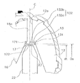
- the impeller core 13 is formed in an annular shape, and a radial portion 131 that extends in the radial direction, and a shaft that extends in the axial direction by bending the outer peripheral portion of the radial portion 131 toward the engine side.
- Direction part 132 Portions 132 a on the transmission side of the radial direction portion 131 and the axial direction portion 132 are fixed to the turbine side edge of the impeller blade 12. Further, a part of the axial side portion 132 on the engine side protrudes from the outlet side edge 12a of the impeller blade 12 to form a first protruding portion 132b.
- the first protrusion 132 b extends to the axial center position C of the torus formed by the impeller blade 12, the turbine blade 16, and the stator blade 22. That is, the tip end of the first protrusion 132b and the axial center position C of the torus are the same position in the axial direction.
- the turbine core 17 is formed in an annular shape and has a radial direction portion 171 extending in the radial direction, an axial direction portion 172 formed by bending an inner peripheral portion of the radial direction portion 171 toward the transmission side and extending in the axial direction, have.
- the radial portion 171 is fixed to the impeller side edge of the turbine blade 16.
- the axial direction part 172 protrudes from the inlet side edge 16a of the turbine blade 16, and is a 2nd protrusion part.
- the second protrusion 172 is located on the inner peripheral side of the first protrusion 132b and extends to the axial center position C of the torus. That is, the tip of the first protrusion 132b and the tip of the second protrusion 172 are at the same position in the axial direction as the axial center position C of the torus.
- the stator core 23 is provided only on the impeller side from the axial center position C of the torus. That is, the stator core 23 is not formed in the region where the turbine core 17 is disposed in the axial position.
- the inner diameter dt of the second projecting portion 172 of the turbine core 17 is smaller than the outer diameter Ds of the stator core 23, and the second projecting portion 172 is disposed close to the outer peripheral portion of the stator blade 22. Further, the second protrusion 172 overlaps the stator blade 22 in the axial direction.
- the lockup device 4 includes a piston 30 and a damper mechanism 31.
- the piston 30 is a disk-shaped member disposed between the front cover 2 and the turbine 6, and an inner peripheral portion thereof is supported on the outer peripheral surface of the turbine hub 18 a so as to be relatively rotatable and movable in the axial direction. ing.
- An annular friction facing 33 is fixed to the engine side of the outer peripheral portion of the piston 30.
- the damper mechanism 31 includes a retaining plate 35, a driven plate 36, and a plurality of torsion springs 37.
- the retaining plate 35 is fixed to the turbine side of the outer peripheral portion of the piston 30.
- the retaining plate 35 has a plurality of cut and raised portions for storing and supporting the torsion spring 37.
- the plurality of torsion springs 37 are accommodated in the retaining plate 35 and supported at both ends in the circumferential direction.
- the driven plate 36 is an annular plate fixed to the outer peripheral side of the turbine shell 15 of the turbine 6.
- the driven plate 36 has a plurality of protruding claws that extend toward the front cover 2 and engage with both ends of the torsion spring 37 in the circumferential direction.
- the impeller core 13 is provided with the first projecting portion 132b. Therefore, the hydraulic oil that has flowed out of the impeller 5 flows into the turbine 6, and the impeller 5 It is possible to suppress the suction of the impeller 5 by the pumping action. More specifically, the position of the impeller blade 12 closest to the inlet side end of the impeller blade 12, that is, the portion where the impeller core 13 is provided is such that the hydraulic oil flowing out from the outlet portion of the impeller 5 is impeller. It is easy to go around to the entrance part of 5.
- the turbine core 17 is also provided with a second protrusion 172, and the second protrusion 172 extends to the axial center position C of the torus. Therefore, the hydraulic oil that has passed through the first protrusion 132b is guided to the turbine 6 side by the second protrusion 172, and can be suppressed from being sucked into the inlet portion of the impeller 5.
- the second projecting portion 172 is disposed close to the outer peripheral portion of the stator blade 22 and overlaps the stator blade 22 in the axial direction. For this reason, the hydraulic oil that has flowed out of the turbine 6 is not easily leaked to the outer peripheral side of the stator 7, and is smoothly guided to the stator 7. In such an embodiment, the flow of the hydraulic oil that has flowed out of the impeller 5 back to the impeller 5 can be suppressed, and a decrease in the torque ratio can be suppressed. Further, the space in the central portion of the torus can be reduced by adopting the shape of the core of the present embodiment as compared with a torque converter having a conventional general core. Therefore, the flow area can be increased without increasing the size of the torque converter, and the capacity coefficient can be increased.
- the second projecting portion 172 has an inner diameter smaller than the outer diameter of the stator core 23 and overlaps the stator blade 22 in the axial direction, the hydraulic oil flowing out from the turbine 6 is smoothly guided to the stator 7.
- FIG. 3 shows another embodiment of the impeller core and the turbine core.
- the shape of the protruding portion of each core is different, and the other configuration is the same as that of the above embodiment.
- the impeller core 13 ′ has a radial direction portion 131 ′ and an axial direction portion 132 ′ as in the above-described embodiment.
- the axial portion 132 ′ has a transmission-side part 132a ′ fixed to the impeller blade 12 and a first protrusion 132b ′ formed to protrude from the outlet-side edge 12a of the impeller blade 12. is doing.
- the first protrusion 132b ′ extends toward the turbine blade 16 beyond the axial center position C of the torus.
- the turbine core 17 ′ has a radial direction portion 171 ′ and an axial direction portion 172 ′.
- the axial portion 172 ′ has a second protrusion 172 ′ that protrudes from the inlet side edge 16 a of the turbine blade 16.
- the second protrusion 172 ' extends toward the impeller blade 12 beyond the axial center position C of the torus. That is, the first protrusion 132b 'and the second protrusion 172' overlap in the axial direction.
- FIG. 4 shows still another embodiment of the impeller core.
- the impeller core 33 of this embodiment is formed in a cylindrical shape, does not have the radial portion in the previous embodiment, and is formed only of the axial portion.
- a part 33 a on the transmission side of the impeller core 33 is fixed to the impeller blade 12, and a part on the engine side is a first projecting portion 33 b that projects from the outlet side edge 12 a of the impeller blade 12.
- the configuration of the first protrusion 33b is the same as the first protrusion 132b ′ in the embodiment shown in FIG.
- the flow path area can be increased without increasing the overall dimensions, and the capacity coefficient can be increased. Moreover, the flow of the hydraulic oil from the impeller outlet to the turbine inlet becomes smooth, and the hydraulic oil flowing out from the impeller can be suppressed from being sucked into the impeller.
Landscapes
- Engineering & Computer Science (AREA)
- General Engineering & Computer Science (AREA)
- Mechanical Engineering (AREA)
- Control Of Fluid Gearings (AREA)
- Structures Of Non-Positive Displacement Pumps (AREA)
Abstract
Description
そこで、特許文献1には、インペラ及びタービンのコアを環状のバーで構成したトルクコンバータが示されている。ここでは、コアが環状のバーで形成されているので、コアを小型化しても強度を維持でき、作動油の流路面積を大きくすることができる。
ここでは、インペラコアにはインペラブレードの出口側端縁から突出する第1突出部が形成され、タービンコアにはタービンブレードの入口側端縁から突出する第2突出部が形成されているので、作動油はインペラからタービンにスムーズに導かれる。また、第1突出部は少なくとも第2突出部の先端まで延びているので、インペラから出た作動油がインペラに戻る流れを抑えることができ、トルク比の低下を抑えることができる。さらに、トルクコンバータの寸法を大きくすることなく流路面積を増大でき、容量係数を大きくすることができる。
本発明の第3側面に係るトルクコンバータは、第1又は第2側面のトルクコンバータにおいて、第1突出部及び第2突出部は軸方向においてオーバラップしている。
本発明の第4側面に係るトルクコンバータは、第1から第3側面のいずれかのトルクコンバータにおいて、ステータコアは、軸方向位置においてタービンコアが配置されている領域には形成されていない。また、第2突出部は、内径がステータコアの外径より小さく、ステータブレードと軸方向においてオーバラップしている。
図1に示すトルクコンバータ1は、エンジンのクランクシャフト(図示せず)からトランスミッションの入力シャフト(図示せず)に動力を伝達するための装置である。図1の左側に図示しないエンジンが配置され、図1の右側に図示しないトランスミッションが配置されている。図1に示すO-O線がトルクコンバータ1の回転軸である。
フロントカバー2は、円板部2aと、外周筒状部2bと、を有している。円板部2aの内周部には、エンジン側に延びるセンタボス8が固定されている。また、円板2aの外周部においてエンジン側には、円周方向に等間隔で複数のナット9が固定されている。外周筒状部2bは円板部2aの外周部からトランスミッション側に延びて形成されている。この外周筒状部2bの先端にインペラ5が溶接により固定されている。この結果、フロントカバー2とインペラ5とによって、内部に作動油が充填される作動油室を形成している。
インペラシェル11の外周部はエンジン側に延びており、前述のように、先端部がフロントカバー2の外周筒状部2bに溶接により固定されている。複数のインペラブレード12は、インペラシェル11の内部に固定されている。インペラコア13は、環状に形成されており、複数のインペラブレード12のタービン側端部を支持している。インペラハブ14は、インペラシェル11の内周部に固定され、トランスミッション側に延びている。
[インペラコア、タービンコア、ステータコア]
次にインペラコア13、タービンコア17、及ぶステータコア23について、詳細に説明する。
ロックアップ装置4は、図1に示すように、ピストン30とダンパー機構31とから構成されている。
ピストン30は、フロントカバー2とタービン6との間に配置された円板状の部材であり、内周部がタービンハブ18aの外周面に相対回転自在に、かつ軸方向に移動可能に支持されている。また、ピストン30の外周部のエンジン側には、環状の摩擦フェーシング33が固定されている。
図示しないエンジンのクランクシャフトからフロントカバー2及びインペラ5にトルクが伝達される。インペラ5に伝達されたトルクは、作動油を介してタービン6に伝達され、タービンハブ18に連結されたトランスミッションの入力シャフトに伝達される。
以上の動作において、トーラス内の作動油は、インペラ5の回転によってインペラシェル11及びインペラブレード12に沿って流れ、タービン6側に導かれる。タービン6内では、タービンシェル15及びタービンブレード16に沿ってステータ7側に流れ、さらにステータ7によって整流されてインペラ5に戻される。
より詳細には、インペラブレード12の出口側端部でもっともインペラブレード12の入口側端部に近い位置、すなわちインペラコア13が設けられている部分は、インペラ5の出口部分から流出した作動油がインペラ5の入口部分に回り込みやすい。
このような実施形態では、インペラ5から流出した作動油がインペラ5に戻る流れを抑えることができ、トルク比の低下を抑えることができる。また、従来の一般的なコアを有するトルクコンバータに比較して、本実施形態のコアの形状を採用することによってトーラス中央部の空間を小さくできる。したがって、トルクコンバータのサイズを大きくすることなく流路面積を増大でき、容量係数を大きくすることができる。
[他の実施形態]
本発明は前記実施形態に限定されるものではなく、本発明の範囲を逸脱することなく種々の変形又は修正が可能である。
具体的には、インペラコア13’は、前記実施形態と同様に、径方向部131’と、軸方向部132’と、を有している。そして、軸方向部132’は、インペラブレード12に固定されたトランスミッション側の一部132a’と、インペラブレード12の出口側端縁12aから突出して形成された第1突出部132b’と、を有している。第1突出部132b’は、トーラスの軸方向中心位置Cを越えてタービンブレード16側に延びている。
(2)図4にインペラコアのさらに別の実施形態を示す。この図4に示す実施形態では、インペラコアの構成のみが図3に示す実施形態と異なっている。
この実施形態のインペラコア33は、筒状に形成されており、先の実施形態における径方向部を有しおらず、軸方向部のみで形成されている。インペラコア33のトランスミッション側の一部33aはインペラブレード12に固定されており、エンジン側の一部はインペラブレード12の出口側端縁12aから突出する第1突出部33bとなっている。第1突出部33bの構成は図3で示す実施形態における第1突出部132b’と同じである。
2 フロントカバー
5 インペラ
6 タービン
7 ステータ
12 インペラブレード
13,13’,33 インペラコア
15 タービンシェル
16 タービンブレード
17 タービンコア
132b,132b’33b 第1突出部
172,172’ 第2突出部
Claims (4)
- エンジンからトランスミッションへ作動油を介してトルクを伝達するトルクコンバータであって、
前記エンジンからトルクが入力されるフロントカバーと、
複数のインペラブレードと、前記複数のインペラブレードを支持する環状のインペラコアと、を有し、前記フロントカバーとともに作動油室を構成するインペラと、
前記インペラブレードに対向して配置された複数のタービンブレードと、前記タービンブレードを支持する環状のタービンコアと、を有し、前記トランスミッションに動力を出力可能なタービンと、
前記インペラの内周部と前記タービンの内周部との間に配置され、前記タービンから前記インペラに流れる作動油を整流するための複数のステータブレードと、前記複数のステータブレードを支持する環状のステータコアと、を有するステータと、
を備え、
前記インペラコアは前記インペラブレードの出口側端縁から軸方向に突出する第1突出部を有し、
前記タービンコアは前記タービンブレードの入口側端縁から軸方向に突出する第2突出部を有し、
前記第2突出部は、前記第1突出部の内周側に位置するとともに、少なくとも前記第1突出部の先端まで延びている、
トルクコンバータ。 - 前記第1突出部及び前記第2突出部は、前記インペラブレード、前記タービンブレード、及び前記ステータブレードによって形成されるトーラスの軸方向中心位置まで延びている、請求項1に記載のトルクコンバータ。
- 前記第1突出部及び前記第2突出部は軸方向においてオーバラップしている、請求項1又は2に記載のトルクコンバータ。
- 前記ステータコアは、軸方向位置において前記タービンコアが配置されている領域には形成されておらず、
前記第2突出部は、内径が前記ステータコアの外径より小さく、前記ステータブレードと軸方向においてオーバラップしている、
請求項1から3のいずれかに記載のトルクコンバータ。
Priority Applications (4)
| Application Number | Priority Date | Filing Date | Title |
|---|---|---|---|
| US14/353,363 US20140290235A1 (en) | 2011-11-24 | 2012-08-08 | Torque converter |
| DE112012004896.2T DE112012004896T5 (de) | 2011-11-24 | 2012-08-08 | Drehmomentwandler |
| KR1020147011743A KR101938610B1 (ko) | 2011-11-24 | 2012-08-08 | 토크 컨버터 |
| CN201280056005.5A CN103930695B (zh) | 2011-11-24 | 2012-08-08 | 扭矩变换器 |
Applications Claiming Priority (2)
| Application Number | Priority Date | Filing Date | Title |
|---|---|---|---|
| JP2011255883A JP5258950B2 (ja) | 2011-11-24 | 2011-11-24 | トルクコンバータ |
| JP2011-255883 | 2011-11-24 |
Publications (1)
| Publication Number | Publication Date |
|---|---|
| WO2013077036A1 true WO2013077036A1 (ja) | 2013-05-30 |
Family
ID=48469497
Family Applications (1)
| Application Number | Title | Priority Date | Filing Date |
|---|---|---|---|
| PCT/JP2012/070264 Ceased WO2013077036A1 (ja) | 2011-11-24 | 2012-08-08 | トルクコンバータ |
Country Status (6)
| Country | Link |
|---|---|
| US (1) | US20140290235A1 (ja) |
| JP (1) | JP5258950B2 (ja) |
| KR (1) | KR101938610B1 (ja) |
| CN (1) | CN103930695B (ja) |
| DE (1) | DE112012004896T5 (ja) |
| WO (1) | WO2013077036A1 (ja) |
Families Citing this family (2)
| Publication number | Priority date | Publication date | Assignee | Title |
|---|---|---|---|---|
| JP6424069B2 (ja) * | 2014-11-11 | 2018-11-14 | ジヤトコ株式会社 | トルクコンバータ |
| US9841093B2 (en) * | 2015-07-30 | 2017-12-12 | Schaeffler Technologies AG & Co. KG | Torque converter with a flat annular core ring |
Citations (3)
| Publication number | Priority date | Publication date | Assignee | Title |
|---|---|---|---|---|
| JPS51123482U (ja) * | 1975-03-31 | 1976-10-06 | ||
| JPS61135051U (ja) * | 1985-02-12 | 1986-08-22 | ||
| JPH09112649A (ja) * | 1995-10-12 | 1997-05-02 | Toyota Motor Corp | 流体式トルクコンバータ |
Family Cites Families (13)
| Publication number | Priority date | Publication date | Assignee | Title |
|---|---|---|---|---|
| US2632397A (en) * | 1949-02-10 | 1953-03-24 | Chrysler Corp | Rotor wheel |
| US2588668A (en) * | 1949-02-23 | 1952-03-11 | Chrysler Corp | Fluid coupling mounting |
| US2660957A (en) * | 1949-03-16 | 1953-12-01 | Chrysler Corp | Rotor wheel |
| JP3211559B2 (ja) * | 1993-09-08 | 2001-09-25 | 日産自動車株式会社 | コアレストルクコンバータ |
| DE19539814C2 (de) * | 1995-10-26 | 1999-08-12 | Mannesmann Sachs Ag | Hydrodynamischer Drehmomentwandler mit Stabilisierungsring an den Schaufelrädern |
| US6220025B1 (en) * | 1999-03-08 | 2001-04-24 | Daimlerchrysler Corporation | Stator for torque converter |
| US6631795B2 (en) * | 2000-07-10 | 2003-10-14 | Yutaka Giken Co., Ltd. | Fluid coupling with baffle plate |
| CN2511834Y (zh) * | 2001-09-19 | 2002-09-18 | 陕西航天动力高科技股份有限公司 | 液力变矩器 |
| KR20030050108A (ko) * | 2001-12-18 | 2003-06-25 | 현대자동차주식회사 | 토크 컨버터용 스테이터 |
| CN100360834C (zh) * | 2003-11-21 | 2008-01-09 | 株式会社豊技研 | 用于车辆的动力传动装置 |
| WO2007118446A2 (de) * | 2006-04-13 | 2007-10-25 | Luk Lamellen Und Kupplungsbau Beteiligungs Kg | Torus-formen für drehmomentwandler |
| DE102008053386A1 (de) * | 2007-11-14 | 2009-05-20 | Luk Lamellen Und Kupplungsbau Beteiligungs Kg | Drehmomentwandler mit Schutzring gegen Schweissverunreinigung |
| CN102072302A (zh) * | 2010-12-16 | 2011-05-25 | 蚌埠市华泰液力变矩器有限公司 | 一种液力变矩器 |
-
2011
- 2011-11-24 JP JP2011255883A patent/JP5258950B2/ja active Active
-
2012
- 2012-08-08 KR KR1020147011743A patent/KR101938610B1/ko active Active
- 2012-08-08 WO PCT/JP2012/070264 patent/WO2013077036A1/ja not_active Ceased
- 2012-08-08 DE DE112012004896.2T patent/DE112012004896T5/de active Pending
- 2012-08-08 US US14/353,363 patent/US20140290235A1/en not_active Abandoned
- 2012-08-08 CN CN201280056005.5A patent/CN103930695B/zh active Active
Patent Citations (3)
| Publication number | Priority date | Publication date | Assignee | Title |
|---|---|---|---|---|
| JPS51123482U (ja) * | 1975-03-31 | 1976-10-06 | ||
| JPS61135051U (ja) * | 1985-02-12 | 1986-08-22 | ||
| JPH09112649A (ja) * | 1995-10-12 | 1997-05-02 | Toyota Motor Corp | 流体式トルクコンバータ |
Also Published As
| Publication number | Publication date |
|---|---|
| DE112012004896T5 (de) | 2014-09-11 |
| JP5258950B2 (ja) | 2013-08-07 |
| KR20140093940A (ko) | 2014-07-29 |
| CN103930695B (zh) | 2016-08-03 |
| JP2013108602A (ja) | 2013-06-06 |
| CN103930695A (zh) | 2014-07-16 |
| KR101938610B1 (ko) | 2019-01-15 |
| US20140290235A1 (en) | 2014-10-02 |
Similar Documents
| Publication | Publication Date | Title |
|---|---|---|
| KR100806242B1 (ko) | 토크 컨버터 | |
| JP3825219B2 (ja) | 流体式トルク伝達装置 | |
| US20110135484A1 (en) | Fluidic torque transfer device | |
| JP2004205012A (ja) | トルクコンバータ | |
| JP4926228B2 (ja) | トルクコンバータの動力伝達装置 | |
| CN104620021B (zh) | 变矩器的定子结构 | |
| JP5258950B2 (ja) | トルクコンバータ | |
| US20110311367A1 (en) | Stator and torque converter | |
| JP5167218B2 (ja) | トルクコンバータ | |
| JP4620785B2 (ja) | ステータ及びトルクコンバータ | |
| JP5242514B2 (ja) | トルクコンバータ | |
| JP2006234059A (ja) | トルクコンバータ | |
| JP4975482B2 (ja) | 流体継手 | |
| JP2011058606A (ja) | 流体式動力伝達装置 | |
| JP6803144B2 (ja) | 流体式回転羽根車 | |
| JP5766149B2 (ja) | トルクコンバータにおけるステータ構造 | |
| JP5688005B2 (ja) | トルクコンバータ | |
| JP6673009B2 (ja) | 流体式トルク伝達装置 | |
| JP4187727B2 (ja) | トルクコンバータ | |
| JP2019138332A (ja) | トルクコンバータ | |
| JP4866757B2 (ja) | 流体式トルク伝達装置 | |
| JP2020079627A (ja) | トルクコンバータ | |
| JP2008215447A (ja) | トルクコンバータ | |
| JP2016130525A (ja) | トルクコンバータ | |
| JP2018071564A (ja) | 流体伝動装置 |
Legal Events
| Date | Code | Title | Description |
|---|---|---|---|
| 121 | Ep: the epo has been informed by wipo that ep was designated in this application |
Ref document number: 12850800 Country of ref document: EP Kind code of ref document: A1 |
|
| WWE | Wipo information: entry into national phase |
Ref document number: 14353363 Country of ref document: US |
|
| ENP | Entry into the national phase |
Ref document number: 20147011743 Country of ref document: KR Kind code of ref document: A |
|
| WWE | Wipo information: entry into national phase |
Ref document number: 1120120048962 Country of ref document: DE Ref document number: 112012004896 Country of ref document: DE |
|
| 122 | Ep: pct application non-entry in european phase |
Ref document number: 12850800 Country of ref document: EP Kind code of ref document: A1 |