WO2013073237A1 - 密閉加圧型混練機の粉末配合剤回収装置及びその回収方法 - Google Patents
密閉加圧型混練機の粉末配合剤回収装置及びその回収方法 Download PDFInfo
- Publication number
- WO2013073237A1 WO2013073237A1 PCT/JP2012/069335 JP2012069335W WO2013073237A1 WO 2013073237 A1 WO2013073237 A1 WO 2013073237A1 JP 2012069335 W JP2012069335 W JP 2012069335W WO 2013073237 A1 WO2013073237 A1 WO 2013073237A1
- Authority
- WO
- WIPO (PCT)
- Prior art keywords
- kneading
- compounding agent
- powder
- air bag
- kneading tank
- Prior art date
- Legal status (The legal status is an assumption and is not a legal conclusion. Google has not performed a legal analysis and makes no representation as to the accuracy of the status listed.)
- Ceased
Links
Images


Classifications
-
- B—PERFORMING OPERATIONS; TRANSPORTING
- B29—WORKING OF PLASTICS; WORKING OF SUBSTANCES IN A PLASTIC STATE IN GENERAL
- B29B—PREPARATION OR PRETREATMENT OF THE MATERIAL TO BE SHAPED; MAKING GRANULES OR PREFORMS; RECOVERY OF PLASTICS OR OTHER CONSTITUENTS OF WASTE MATERIAL CONTAINING PLASTICS
- B29B17/00—Recovery of plastics or other constituents of waste material containing plastics
- B29B17/0005—Direct recuperation and re-use of scrap material during moulding operation, i.e. feed-back of used material
-
- B—PERFORMING OPERATIONS; TRANSPORTING
- B08—CLEANING
- B08B—CLEANING IN GENERAL; PREVENTION OF FOULING IN GENERAL
- B08B17/00—Methods preventing fouling
-
- B—PERFORMING OPERATIONS; TRANSPORTING
- B01—PHYSICAL OR CHEMICAL PROCESSES OR APPARATUS IN GENERAL
- B01F—MIXING, e.g. DISSOLVING, EMULSIFYING OR DISPERSING
- B01F35/00—Accessories for mixers; Auxiliary operations or auxiliary devices; Parts or details of general application
-
- B—PERFORMING OPERATIONS; TRANSPORTING
- B01—PHYSICAL OR CHEMICAL PROCESSES OR APPARATUS IN GENERAL
- B01D—SEPARATION
- B01D46/00—Filters or filtering processes specially modified for separating dispersed particles from gases or vapours
- B01D46/02—Particle separators, e.g. dust precipitators, having hollow filters made of flexible material
- B01D46/04—Cleaning filters
-
- B—PERFORMING OPERATIONS; TRANSPORTING
- B01—PHYSICAL OR CHEMICAL PROCESSES OR APPARATUS IN GENERAL
- B01F—MIXING, e.g. DISSOLVING, EMULSIFYING OR DISPERSING
- B01F23/00—Mixing according to the phases to be mixed, e.g. dispersing or emulsifying
- B01F23/60—Mixing solids with solids
-
- B—PERFORMING OPERATIONS; TRANSPORTING
- B01—PHYSICAL OR CHEMICAL PROCESSES OR APPARATUS IN GENERAL
- B01F—MIXING, e.g. DISSOLVING, EMULSIFYING OR DISPERSING
- B01F27/00—Mixers with rotary stirring devices in fixed receptacles; Kneaders
- B01F27/60—Mixers with rotary stirring devices in fixed receptacles; Kneaders with stirrers rotating about a horizontal or inclined axis
- B01F27/70—Mixers with rotary stirring devices in fixed receptacles; Kneaders with stirrers rotating about a horizontal or inclined axis with paddles, blades or arms
-
- B—PERFORMING OPERATIONS; TRANSPORTING
- B29—WORKING OF PLASTICS; WORKING OF SUBSTANCES IN A PLASTIC STATE IN GENERAL
- B29B—PREPARATION OR PRETREATMENT OF THE MATERIAL TO BE SHAPED; MAKING GRANULES OR PREFORMS; RECOVERY OF PLASTICS OR OTHER CONSTITUENTS OF WASTE MATERIAL CONTAINING PLASTICS
- B29B7/00—Mixing; Kneading
- B29B7/02—Mixing; Kneading non-continuous, with mechanical mixing or kneading devices, i.e. batch type
- B29B7/06—Mixing; Kneading non-continuous, with mechanical mixing or kneading devices, i.e. batch type with movable mixing or kneading devices
- B29B7/10—Mixing; Kneading non-continuous, with mechanical mixing or kneading devices, i.e. batch type with movable mixing or kneading devices rotary
- B29B7/18—Mixing; Kneading non-continuous, with mechanical mixing or kneading devices, i.e. batch type with movable mixing or kneading devices rotary with more than one shaft
- B29B7/183—Mixing; Kneading non-continuous, with mechanical mixing or kneading devices, i.e. batch type with movable mixing or kneading devices rotary with more than one shaft having a casing closely surrounding the rotors, e.g. of Banbury type
-
- B—PERFORMING OPERATIONS; TRANSPORTING
- B29—WORKING OF PLASTICS; WORKING OF SUBSTANCES IN A PLASTIC STATE IN GENERAL
- B29B—PREPARATION OR PRETREATMENT OF THE MATERIAL TO BE SHAPED; MAKING GRANULES OR PREFORMS; RECOVERY OF PLASTICS OR OTHER CONSTITUENTS OF WASTE MATERIAL CONTAINING PLASTICS
- B29B7/00—Mixing; Kneading
- B29B7/02—Mixing; Kneading non-continuous, with mechanical mixing or kneading devices, i.e. batch type
- B29B7/06—Mixing; Kneading non-continuous, with mechanical mixing or kneading devices, i.e. batch type with movable mixing or kneading devices
- B29B7/10—Mixing; Kneading non-continuous, with mechanical mixing or kneading devices, i.e. batch type with movable mixing or kneading devices rotary
- B29B7/18—Mixing; Kneading non-continuous, with mechanical mixing or kneading devices, i.e. batch type with movable mixing or kneading devices rotary with more than one shaft
- B29B7/20—Mixing; Kneading non-continuous, with mechanical mixing or kneading devices, i.e. batch type with movable mixing or kneading devices rotary with more than one shaft with intermeshing devices, e.g. screws
-
- B—PERFORMING OPERATIONS; TRANSPORTING
- B29—WORKING OF PLASTICS; WORKING OF SUBSTANCES IN A PLASTIC STATE IN GENERAL
- B29B—PREPARATION OR PRETREATMENT OF THE MATERIAL TO BE SHAPED; MAKING GRANULES OR PREFORMS; RECOVERY OF PLASTICS OR OTHER CONSTITUENTS OF WASTE MATERIAL CONTAINING PLASTICS
- B29B7/00—Mixing; Kneading
- B29B7/02—Mixing; Kneading non-continuous, with mechanical mixing or kneading devices, i.e. batch type
- B29B7/22—Component parts, details or accessories; Auxiliary operations
- B29B7/24—Component parts, details or accessories; Auxiliary operations for feeding
- B29B7/246—Component parts, details or accessories; Auxiliary operations for feeding in mixers having more than one rotor and a casing closely surrounding the rotors, e.g. with feeding plungers
-
- B—PERFORMING OPERATIONS; TRANSPORTING
- B29—WORKING OF PLASTICS; WORKING OF SUBSTANCES IN A PLASTIC STATE IN GENERAL
- B29B—PREPARATION OR PRETREATMENT OF THE MATERIAL TO BE SHAPED; MAKING GRANULES OR PREFORMS; RECOVERY OF PLASTICS OR OTHER CONSTITUENTS OF WASTE MATERIAL CONTAINING PLASTICS
- B29B7/00—Mixing; Kneading
- B29B7/80—Component parts, details or accessories; Auxiliary operations
- B29B7/84—Venting or degassing ; Removing liquids, e.g. by evaporating components
Definitions
- the present invention relates to a recovery device for recovering a powder compounding agent ejected in a closed pressure type kneader that kneads a high-viscosity kneading material such as rubber, plastic, and ceramics in a batch manner, and a method for recovering a powder compounding agent using the device. is there.
- a closed-type kneader in which a pair of kneading rotors are pivoted in a kneading tank and kneaded by pressurization of the kneading material while rotating the pair of kneading rotors is not particularly limited. Widely known.
- known batch type kneading machines for high viscosity kneading materials such as rubber, plastic, ceramics, etc. include open type and hermetic pressure type kneaders.
- the internal pressure rise prevention device 10 in which a pressure adjusting air bag 28 that can be inflated and contracted is connected to the side wall at the upper position of the kneading tank 16 via a chute 34. Provided that when the pressure in the kneading tank rises, the gas in the tank flows into the air bag, and when the internal pressure of the kneading tank decreases, the gas in the air bag is recirculated into the kneading tank. ing.
- This internal pressure rise prevention device 10 suppresses the pressure in the kneading tank from being increased by pressurizing the gas corresponding to the descending distance of the pressure lid when the pressure lid pushes the kneaded material into the kneading tank. It is effective to prevent the pressure increase that causes leakage of the powder compounding agent introduced into the shaft seal structure of the kneading machine and the sealing part of the kneading material charging part or discharging part door.
- the above-mentioned closed pressure type kneader also has a function of preventing the powder compounding agent charged in the kneading tank from being ejected from the periphery of the opening of the kneading tank to the outside and deteriorating the surrounding environment. Is.
- the gas pressurized in the kneading tank as the pressurizing lid is lowered to the kneading tank is the opening of the kneading tank.
- the kneading machine is equipped with an internal pressure rise prevention device 10 including an air bag 28.
- the mixed phase gas containing the above powder compounding agent is accumulated and accumulated in the airbag, and it is refluxed into the kneading tank by the instantaneous pressure drop in the kneading tank due to the raising operation of the pressure lid, thereby Then, the powder compounding agent sprayed upwards from the pressure lid as a dust flow is taken in and recovered by the kneaded product during the kneading.
- the air bag body 30 needs to have at least a capacity corresponding to the amount of air that is moved by the vertical movement of the ram cylinder 24. There is a possibility that the gas flowing into the airbag body 30 may exceed the capacity of the airbag body due to the input of more raw materials than the planned input amount or the temperature rise of the gas in the kneading tank.
- a branch duct 50 that constitutes a safety flow path for avoidance is connected and the gas flowing into the airbag body exceeds its capacity, a part of the gas is discharged through the branch duct 50 to an external dust collector. I can do it.
- the airbag 28 connected to the kneading tank via the chute 34 has a relatively large diameter because it requires a capacity to allow a large amount of gas to flow in.
- the flow rate of the gas flowing into the airbag 28 through 34 is rapidly reduced, and the powder having a large particle size in the mixed phase air flow of the powder compound is settled and deposited early, and the medium particle size powder is air-mixed as a mixed gas phase.
- the fine powder is sucked into the external dust collector through the branch duct 50. Therefore, it is considered that the recovery rate and the recovery amount are limited by the particle size and weight of the powder compounding agent.
- the gas discharged to the dust collector through the branch duct 50 contains a lot of powder additives as dust, and in particular, fine dust in the exhaust from the branch duct is separated and recovered.
- it is not possible to improve the working environment it is impossible to recover the various powder additives injected into the air bag 28 with high efficiency and return them to the kneading material.
- nearly half of the powder compounding agent to be discarded is disposed of as dust, and in order to increase the value recovery rate and bring the compounding quality close to the design quality, further improvement in the value recovery rate is required.
- the technical problem of the present invention is that the closed pressure type kneader according to Patent Document 1 provided with an air bag constituting the internal pressure rise prevention device further improves the performance of powder compounding agent recovery, more specifically, Even when the gas flowing into the air bag may exceed the capacity of the air bag, a large amount of powder compounding agent as dust when discharging a part of the gas to the outside through a branch duct connected to the air bag By including it with simple means and returning it to the kneading tank, it is possible to bring the blending quality close to the design quality at a low cost, and as a result, the valuable recovery rate can be significantly increased.
- a powder compounding agent recovery device attached to a closed pressure type kneader for recovering the powder compounding agent ejected from the kneading tank, wherein the pressure lid hoistway of the kneading tank is opened and closed by the pressure lid
- the upper end of the airbag is sealed and sealed in the above-mentioned cylindrical shape.
- a branch duct that can be cut off to the outside as a safety flow path that avoids excessive pressure is connected to the upper part of the airbag, and the airbag is kneaded inside the airbag.
- a filter cylinder for filtering and capturing the powder compound entrained by the gas flowing in from the tank side is suspended, and the powder compound captured in the filter cylinder is returned to the kneading tank by the pressurized gas accumulated in the airbag. It is characterized by being made possible.
- the filter tube suspended in the air bag is squeezed by squeezing the upper part of the cylindrical filter cloth material.
- the upper part is sealed with a small diameter, and the lower end of the filter cylinder is connected to the enlarged diameter part of the upper end of the ventilation chute together with the lower end of the air bag.
- the filter cylinder has a conical shape in which the envelope surface in contact with the inner bottom surface of the Kakutani, which is generated by squeezing the upper part of the cylindrical filter cloth material by folding,
- the inner surface of the bag is configured to have a conical shape in which a gap is held on the entire circumferential surface.
- an openable / closable charging door for charging the kneading material into the kneading tank
- a charging In a hermetic pressure type kneader provided with a compounding agent hopper for charging the powder compounding agent through a powder chute having a valve for the above, to the ventilation chute and the branch duct connecting the air bag to the kneading tank
- Each of the open / close dampers may be provided so that the open / close dampers can be opened or closed manually or automatically by a control device.
- the powder that assists in removing the powder compounding agent trapped in the filter tube by the pressurized gas in the air bag and refluxing it to the kneading tank As a compounding-off mechanism, a nozzle for injecting a gas for squeezing into the outer region of the filter cylinder in the air bag is provided, and gas is supplied to the nozzle through a ventilation control valve for controlling the amount of ventilation. Configured as connected to the source.
- the powder compounding agent recovery method of the closed pressure type kneader according to the present invention for solving the above-mentioned problem is a powder compounding agent in which the kneading material introduced into the kneading tank is introduced from a compounding hopper through a powder chute.
- the powder compounding agent recovery device for recovering the agent can be connected to an expandable / contractible air bag via a vent chute communicating with the pressure lid hoistway of the kneading tank, and can be disconnected to the outside of the air bag.
- the venting chute and the branch duct are provided with open / close dampers, respectively.
- the charging valve provided on the powder chute is opened, and at the same time, the opening / closing damper provided on the ventilation chute is opened to knead the kneading tank.
- the powder compounding agent is charged on the top, and the powder compounding agent entrained by the gas jetted from the kneading tank side to the air bag side is filtered and trapped by a filter tube provided inside the air bag, and the gas is mixed with air.
- the bag Pressurize into the bag, and then the gas jetted from the kneading tank as the pressurization lid for kneading the kneaded material and powder compounding agent and the powder compounding agent accompanying it are put into the air bag.
- the air bag is pressurized with the gas, and the powder compounding agent entrained in the gas is captured by the filter tube, and the kneading rotor performs the kneading operation.
- the gas in the air bag filled in the pressurized state flows into the kneading tank that becomes negative pressure at the moment when the pressure lid is raised, and the powder that has been separated and captured in the filter tube by the air flow
- the compounding agent is poured into the kneading tank, and then the pressure lid is lowered to perform the final kneading operation of kneading the powder compounding agent returned to the kneading tank, and the series of kneading operations is completed. To do.
- the filter tube having the above-described structure is used as a filter tube suspended in the air bag, and the filter tube is tubed by the air bag with an internal pressure.
- the inner surface of the bag is configured to have a conical shape in which a gap is held on the entire circumferential surface.
- the gas filled in the pressurized state in the air bag is kneaded by the pressure drop in the kneading tank accompanying the rise of the pressure lid after the kneading operation. When flowing into the tank, it is configured to operate an additional drop-off mechanism for dropping off the powder compounding agent trapped in the filter tube, so that the powder compounding agent in the filter tube is discharged.
- the above-mentioned closed kneader is equipped with a powder compounding agent recovery device having a configuration similar to the internal pressure rise prevention device of the closed kneader disclosed in Patent Document 1, but in carrying out the above powder compounding agent recovery method.
- the pressure relief gap provided at the periphery of the open / close-type material charging door in a known kneader can be sealed in a sealed state.
- the air passage from which the gas can flow out from the inside of the kneading machine is only a flow path leading to the air bag through the air flow chute, and the air bag provided in the flow path is used for raising and lowering the pressure lid and the material.
- Absorption of changes in atmospheric pressure and airflow in the kneading machine at the time of charging can prevent an increase in atmospheric pressure in the kneading machine and suppress dust scattering from each part of the body of the kneading machine.
- the present invention is equipped with a dust collector that constitutes an outer enclosure that can be expanded and contracted with a double structure in which a filter tube is incorporated inside the air bag. Therefore, like a conventional kneader, the material input door is opened. There is no need to install a large dust collection hood on the door to suck dust generated during the time, and suction for dust collection. By capturing in the filter tube, the material recovery rate can be remarkably improved.
- the powder compounding agent recovery device has a structure that is suspended in a space, an air bag that does not use electrical energy, a filter tube disposed therein, a mechanism for removing the powder compounding agent trapped in the filter tube, etc. It is compactly formed by a flexible, deformable and expandable outer enclosure with an air backwashing system, and it is extremely simple and economical compared to conventional dust collection equipment installed around a kneader. It can be configured as a highly functional device.
- the powder compounding agent recovery device and the recovery method of the closed pressure type kneader of the present invention described in detail above, in the known closed pressure type kneader equipped with the air bag constituting the internal pressure rise prevention device, the powder compounding The agent recovery performance is further improved, and more specifically, even if the gas flowing into the airbag exceeds the capacity of the airbag, a part of the gas passes through a branch duct connected to the airbag.
- the powder compounding agent carried in a high concentration in the gas ejected from the kneading tank is filtered and captured by the filter tube in the air bag without flowing out to the outside, and it is returned to the kneading tank.
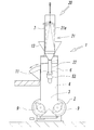
- FIG. 3 It is a front view which shows the Example of the closed pressure type kneader provided with the powder compounding agent collection
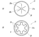
- (A) is a cross-sectional view at the aa position in FIG. 3, and
- (B) is a cross-sectional view at the bb position.
- FIGS. 1 to 4 show an example of an embodiment of the closed pressure type kneader 1 equipped with the powder compounding agent collecting apparatus 20 according to the present invention
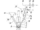
- FIGS. 5 to 8 show the operating state of the powder compounding agent collecting apparatus 20.
- a hermetic pressure-type kneader 1 shown in the figure which kneads a high-viscosity kneading material such as rubber, plastic, ceramics, etc. in a batch system, pressurizes upward by a pressure lid 6 that can be opened and closed by a pressure mechanism 7 comprising a fluid pressure cylinder.
- a kneading tank 2 is provided in which the lid hoistway 3 can be closed.
- the kneading material is kneaded by two kneading rotors 9 arranged adjacent to each other, and the pressure lid 6
- the kneading tank 2 opened and closed by the pressure lid hoistway 3 is provided with a door 11 for opening and closing the high-viscosity kneading material in the kneading tank 2.
- a compounding hopper 13 for supplying the powder compounding agent P for kneading to the kneading tank 2 through the powder chute 14 is provided on the side surface of the surrounding wall 4 of the pressure lid hoistway 3.
- the pressure lid 6 holds the inside of the kneading tank 2 in a pressurized state.
- the internal pressure increases to some extent due to a temperature rise or the like, the internal pressure is increased from the surroundings by floating. It has a function to escape.
- the pressure relief gap as provided at the periphery of the open / close type material charging door in a known pressure type kneader is sealed, and the pressure lid hoistway 3
- the air passage through which the gas flows out from the kneading machine is a flow path leading to the air bag 21 through the opened charging door 11, the powder chute 14, and the air chute 22 described later.
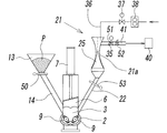
- the other side of the surrounding wall 4 of the pressurization lid hoistway 3 of the kneading tank 2 is connected to the main part of the powder compounding agent collecting device 20.
- the cylindrical airbag 21 which comprises a part is connected through the ventilation chute 22.
- This powder compounding agent recovery device 20 partially modifies the configuration of the internal pressure rise prevention device according to Patent Document 1, and in addition to the configuration, as will be described in detail below, the working environment is remarkably improved.
- the powder compounding agent ejected from the kneading tank 2 is efficiently recovered and returned to the kneaded material, which is effective in improving the blending quality of the product and sucked into a dust collector installed outside the kneader.
- the powder compounding agent ejected from the kneading tank 2 is efficiently recovered and returned to the kneaded material, which is effective in improving the blending quality of the product and sucked into a dust collector installed outside the kneader.
- it has a function that contributes to a significant reduction in waste collected as dust.
- the air bag 21 is formed of a non-breathable material having deformable flexibility and a certain degree of elasticity.
- the pressure in the kneading tank 2 rises, and the powder compounding agent P is accompanied by the kneading tank 2.
- the powder compounding agent adhering to the inner surface of the filter cylinder 25 (to be described later) in the air bag 21 is removed by the air flow and recovered into the kneading tank 2.
- the powder compounding agent is taken into the compound being kneaded and kneaded as a compounding agent.
- the air bag 21 will be described more specifically. As shown in detail in FIGS. 3 and 4, the air bag 21 has a hard circular opening at the upper edge of the cylindrical bag body 21 a.
- the top of the top plate 21b is hermetically fixed to the upper surface of the top plate 21b, thereby sealing the upper end of the bag body 21a in a cylindrical shape and connecting the lower end of the bag body 21a to the upper end of the ventilation chute 22. It connects with the upper end opening cylinder part 23a of the funnel-shaped enlarged diameter part 23, and the lower end of the said bag main body 21a is the cylinder shape sewn on the lower end of the filter cylinder 25 arrange
- the outer chute 22 of the ventilation chute 22 is externally fitted to the upper end opening cylindrical portion 23 a and is connected by tightening with a band 27.
- the said airbag 21 and the filter tube 25 are comprised as what makes the double structure which provided the clearance gap between them.
- the filter tube 25 suspended in the air bag may be basically conical with the upper part being squeezed and the lower part being open, but the filter cylinder 25 is suspended in the air bag 21 having a limited volume.
- the fold-folded portion 25a of four or more folds is formed on the upper edge of the cylindrical filter cloth material.
- the upper and lower ends of the filter cloth material are sealed with a small diameter, and the intermediate portion is close to the uneven shape as shown in FIG.
- the upper part is basically a conical shape with a small diameter, but the overall shape is not necessarily limited to this.
- the envelope surface E contacting the inner bottom surface of the Kakutani, which is produced by squeezing the upper part of the cylindrical filter cloth material of the filter tube 25, is substantially conical. It will take shape.
- the bag body 21a is suspended by a hook ring 28 provided at the center of the inner surface of the circular top plate 21b of the airbag 21 by engaging the hook 25b at the upper end of the filter tube 25 with the internal pressure.
- the filter tube 25 is configured to have a generally conical shape between the inner surface of the air bag 21 and a gap that is maintained over the entire circumference and the entire length. It is formed so as to have a volume space in which a gas sufficient to wipe off the powder compounding agent adhering to the inner surface is accommodated.
- the filter tube 25 is formed so that the filtration area of the filter tube 25 is as large as possible in the air bag 21 while maintaining the above-mentioned gap on the entire circumferential surface between the filter tube 25 and the inner surface of the air bag 21. Is done.
- the above-described configuration of the filter tube 25 is particularly effective for improving the recovery rate of the powder compounding agent.
- a cylindrical lower end portion of the filter tube 25 is fixed to the upper end opening tube portion 23a of the funnel-shaped enlarged diameter portion 23 in the ventilation chute 22, and at that time, a reinforcement that forms a tube shape at the lower end of the filter tube 25 is provided.
- the piece 26 is sewn, and the lower end of the airbag 21 together with the reinforcing piece 26 is externally fitted to the upper end opening cylindrical portion 23a of the enlarged-diameter portion 23 of the ventilation chute, and these are fastened with a band 27, and the filter cylinder It is effective for letting the lower end of 25 itself hang down in the opening cylinder part 23a of the said enlarged diameter part 23 in order to suppress the leakage of a powder compounding agent.
- the filter tube 25 having a large filtration area described above with reference to FIG. 4 is advantageous also in that the trapping rate of the powder compounding agent is improved by lowering the filtration rate of the pressure-off pressurized aeration. It is a thing.
- the powder compounding agent separated and trapped on the entire surface of the filter tube 25 is caused to flow back into the kneading tank 2 when the gas in the air bag 21 is refluxed into the kneading tank 2. It is wiped out at a stretch. Therefore, the flexibility and the internal volume of the material in the air bag 21 are determined by mixing the powder trapped in the filter tube 25 when the pressure lid 6 is raised and the internal pressure of the kneading tank 2 is lowered as will be described later. It should also be considered to form the wind pressure and wind speed necessary to remove the agent.
- a filter cylinder 25 is assembled as a double structure inside the air bag 21 and suspended, and the filter is lowered by pressure reduction in the kneading tank 2 as the pressure lid 6 rises.
- the powder compounding agent P trapped in the cylinder 25 can be returned to the kneading tank 2 by the pressurized gas accumulated in the airbag 21, but only by the pressurized pressure in the airbag 21 is attached to the inner surface of the filter cylinder 25 by filtration. It is difficult to dislodge the powder compounding agent P, and the gas amount and pressure due to the pressurization may be insufficient to recirculate the powder compounding agent P into the kneading tank 2.
- the air bag 21 is provided with an additional removal mechanism for removing the powder compound P captured in the filter tube 25, and operates when the gas amount and pressure in the air bag 21 are insufficient.
- the powder compounding agent for the filter tube 25 And configured to shake off the kneading tank 2 side.
- a filter plate 25 is provided in the air bag 21 on the top plate 21 b that holds the top of the air bag 21.
- a single or a plurality of nozzles 36 for blowing gas to be blown off are disposed in the outer region of the gas, and connected to a gas supply source 38 via a ventilation control valve 37 for controlling the amount of ventilation.
- a configuration in which the powder compounding agent P on the filter tube 25 is removed to the kneading tank 2 side by forcibly ventilating compressed air or the like with a higher pressure and a necessary minimum aeration amount is suitable.
- the wiping-out function can be enhanced with a small amount of ventilation.
- the additional wiping mechanism adheres to the inner surface of the filter tube 25 due to a sticky powder compounding agent and a volatile component generated from the kneaded material that is heated as the kneading progresses, and it is relatively peeled off. Even when a compounding agent or the like that is difficult to remove is removed, it can be applied as an aid to the peeling action.
- the airbag 21 is basically cylindrical, it expands and contracts in the longitudinal direction in response to expansion and contraction as shown in FIGS. It is suspended by a wire 30 through a hook 29 provided at the center of the upper surface of the plate 21b, and the other end of the wire 30 is wound around a plurality of pulleys 31 positioned at the upper part of the airbag 21 and is used for balancing at the tip. By suspending the heavy cone 32, it hangs up and down on the ceiling or the like so as to keep its cylindrical shape even if it always expands and contracts.
- the inflation of the airbag 21 due to the increase in the internal pressure is performed by an overpressure inflation detector 46 that is arranged around the airbag 21 and detects its expansion, or a pressure sensor in the airbag 21 as necessary. It can also be detected by a control device such as that described below, and can also be used for controlling the opening / closing operation of the opening / closing dampers 51, 53, etc. via a control device to be described later.
- a flexible branch duct 35 communicating with the outside is connected to the upper portion of the airbag 21 through a dust collector 40.
- This branch duct 35 forms a safety channel for avoiding the destruction of the bag body 21a, and the gas flowing into the bag body 21a from the kneading tank 2 side is within a range in which the bag body 21a can be enlarged.
- a case where the capacity is exceeded is detected by the overpressure expansion detector 46 or the like, and a part of the gas can be discharged to the external dust collector 40 through the branch duct 35.
- the dust collector 40 those used for other purposes can be used, and the branch duct 35 can be connected to the suction duct 41.
- a filter cylinder 25 is provided in the air bag 21 so that the powder compounding agent does not flow into the air bag 21 beyond the filter cylinder 25.
- the charging door 11 is opened and rubber or rubber chemicals are used.
- the dust collector 40 collects these dusts through a ventilation chute and suppresses the scattering. It can also function effectively.
- reference numeral 60 denotes a work table.
- the hermetic pressure type kneader 1 and the powder compounding agent collecting device 20 are controlled to be driven automatically or semi-automatically by a control device (not shown) or the like, and each part has valves, dampers, and the like to be controlled.
- a control device not shown
- each part has valves, dampers, and the like to be controlled.
- operations including those configurations and the like will be described together with a method of recovering the powder compounding agent by the powder compounding agent recovery apparatus 20.
- the closed pressure type kneader 1 and the powder compounding agent recovery device 20 can be controlled automatically or semi-automatically by the control device or the like, but without performing the automatic or semi-automatic drive control, Needless to say, the drive can be controlled by arbitrary means.
- FIG. 5 shows a preparatory state before the start of kneading in the above closed pressure type kneader 1.
- the charging valve 50 provided on the powder chute 14 of the compounding hopper 13 for supplying the powder compounding agent P is closed, and the compounding agent hopper 13 has a predetermined amount of the powder compounding agent P measured in advance.
- the closing valve 50 is automatically opened / closed by a signal from the control device at a necessary opening / closing timing.
- the branch duct 35 connected to the upper portion of the air bag 21 and connected to the suction duct 41 of the dust collector 40 is provided with an open / close damper 51 that opens and closes in response to a signal from the control device.
- an adjustment damper 52 for setting the suction air volume to the dust collector 40 is provided, and the ventilation chute 22 between the airbag 21 and the hoistway 3 of the kneading tank 2 is also controlled to open and close by a signal from the control device.
- the open / close damper 53 is provided, but these open / close mechanisms are all open in the state before the start of kneading in FIG.
- the open / close damper 51 is opened, the inside of the airbag 21 is connected to the suction duct 41 of the dust collector 40 through the branch duct 35, and the kneading tank 2 with which the ventilation chute 22 communicates is opened to the outside.
- the air bag 21 is in a state of being deflated due to the suction by the suction duct 41, and the filter tube 25 in the air bag 21 is crushed by the air bag 21 Even if it exists, if the gas from the kneading tank 2 flows in, it will return to the original form.
- the charging door 11 (FIG. 2) for charging the kneading material into the kneading tank 2 is opened based on the signal.
- a high-viscosity kneading material such as rubber, plastic, or ceramic is put into the kneading tank 2.
- the charging door 11 can also be manually operated. After the kneading material is charged, when the pair of kneading rotors 9 are rotated and the charging door 11 is closed, the pressure lid 6 is lowered by the pressure mechanism 7 and the pressure lid hoistway 3 of the kneading tank 2 is closed.
- the kneaded material lump is crushed and kneaded by the rotation of the kneading rotor 9. This is kneading in the first step.
- the open / close damper 51 of the branch duct 35 is open, the open / close damper 53 of the ventilation chute 22 is closed, and the airbag 21 is deflated. It is in a state (not shown).
- the kneading in the first step is performed for a set time, and after the elapse of the time, the pressure lid 6 is raised, and the open / close damper 51 provided in the charging door 11 and the branch duct 35 is closed.
- the valve 50 for injection in the powder chute 14 of the agent hopper 13 and the open / close damper 53 of the ventilation chute 22 are automatically opened simultaneously, and the powder compound P waiting in the compound hopper 13 is passed through the powder chute 14.
- the pressure lid 6 is poured down into the surrounding wall 4 surrounding the pressure lid hoistway 3 of the kneading tank 2 with the pressure lid 6 stopped at the upper limit, and the valve 50 is closed after that.
- the powder compounding agent P As the powder compounding agent P is introduced, a volume equal amount of gas flows into the air bag 21 through the ventilation chute 22, and the gas contains a large amount of the powder compounding agent P that is scattered by the flow. It is accommodated in the airbag 21 together with the gas, and the inside of the airbag 21 is pressurized by the gas. Of course, the powder compounding agent P flowing into the airbag 21 is filtered and captured in the filter tube 25. FIG. 6 shows this state.
- the pressure lid 6 is lowered by the pressure mechanism 7, and the kneading of the second step is started.
- This kneading in the second step is to knead the high-viscosity kneading material charged in the kneading tank 2 and the powder compounding agent P introduced from the compounding agent hopper 13.
- the pressure lid hoistway 3 of the kneading tank 2 is closed by the lowering of the pressure lid 6.
- the gas corresponding to the descending distance of the pressure lid 6 in the surrounding wall 4 of the path 3 is compressed, and passes above the pressure lid 6 through the gap between the pressure lid 6 and the surrounding wall 4 of the pressure lid hoistway 3.
- the gas that passes through the filter cylinder 25 from the kneading tank 2 together with the powder compounding agent P that is ejected and flows into the bag body 21a of the airbag 21 is further pressurized by the gas.
- the powder compounding agent P entrained in the gas is separated and captured when passing through the filter tube 25.
- the air bag 21 into which the gas obtained by separating the powder compounding agent P by the filter tube 25 flows is provided with a conical filter tube 25 having a small diameter at the upper portion, and forms a tube shape of the filter tube 25.
- the lower end is connected to the ventilation chute 22 together with the lower end of the airbag 21, and the filter cylinder 25 is held in a state having a gap between the inner surface of the airbag 21 and the entire circumferential surface.
- the open / close damper 53 provided on the ventilation chute 22 between the airbag 21 and the kneading tank 2 is closed.
- the open / close damper 51 of the branch duct 35 connected to the suction duct 41 of the dust collector 40 is also closed, the filter body 25 and the bag body 21a of the air bag 21 are filled with the powder mixture that has flowed in.
- the gas containing P is held in a bulging pressure state. In these operation stages, if the pressurization in the airbag 21 increases abnormally for some reason, it is detected by the overpressure expansion detector 46 or the like, or at the operator's discretion, the branch duct 35.
- the opening / closing damper 51 is opened, the air volume is adjusted by the adjusting damper 52 as necessary, and the air bag 21 is communicated with the suction duct 41 of the dust collecting device 40 through the branch duct 35 to reduce its internal pressure. Also in this case, since the powder compounding agent is captured by the filter tube 25, it is not discharged to the dust collector 40.
- the open / close damper 51 of the branch duct 35 is opened, the open / close damper 51 is closed by the control device in synchronization with the rising start of the pressure lid 6.
- the gas filled in the air bag 21 in a pressurized state flows into the kneading tank 2 due to the difference between the pressure in the kneading tank 2 and the pressure in the air bag 21,
- the powder compounding agent P separated and captured on the entire inner surface of the filter tube 25 is swept away into the kneading tank 2 at a stretch, and the air bag 21 is deflated accordingly.
- the open / close damper 51 of the branch duct 35 is opened, the pressure lid 6 is gently lowered to the position where the pressure lid hoistway 3 of the kneading tank 2 is closed, and the final kneading operation in the third step is performed.
- the kneading operation is terminated.
- a large amount of the powder compounding agent P was not put into the kneading tank as in the stage of starting the kneading of the second step, there was a powder compounding agent P accompanying the air flow from the pressure lid 6. Even so, it is extremely small. As a result, the state shown in FIG. 5 is restored.
- the air bag 21 in which the filter tube 25 forms a tube shape Since the inner surface and the entire peripheral surface of the cylinder are held in a state having a gap, the powder compounding agent P trapped in the filter tube 25 is returned to the kneading tank 2 side very efficiently by backwash flow of the accumulated gas. Can do.
- the gas for blowing off is blown from the nozzle 36 into the outer region of the filter cylinder 25 in the air bag 21 by operating the ventilation control valve 37 each time,
- the ventilation control valve 37 may be controlled so as to supply the air for removing from the nozzle 36.
- the powder compounding agent P can be removed for each batch and kneaded into the same batch being kneaded, so that it can greatly contribute to resource recovery compared to the conventional method, and is particularly suitable. It has been confirmed that the powder compounding agent P can be separated by filtration with a high efficiency of 99% or more from the mixed-phase airflow by selecting the filter cylinder.
- the powder chute 14 of the compounding agent hopper 13 for supplying the powder compounding agent P is provided in the third step. Then, the charging valve 50 is closed, and the hopper 13 is charged with the required amount of the powder mixture P measured for the kneading operation of the next batch. Further, the open / close damper 53 provided in the ventilation chute 22 between the airbag 21 and the kneading tank 2 is closed, and the open / close damper 51 of the branch duct 35 connected to the suction duct 41 of the dust collector 40 is opened. Waiting for the start of kneading of the batch.
- the powder compounding agent recovery method by the powder compounding agent recovery device 20 described above a large amount of the powder compounding agent is not discarded as dust, but is captured by simple means and returned to the kneading tank.
- the work environment can be remarkably improved, and at the same time, the valuable recovery rate can be remarkably increased to bring the blending quality closer to the design quality.
- the closed-type kneader equipped with the powder compounding agent recovery device of the present invention can greatly reduce the dust collection function required for one kneader by a factor of 2 to 3 and achieve a significant reduction in power consumption. can do.
- Step 1 to Step 3 are examples of typical kneading operations in the above-mentioned closed type kneader, and the kneading of the high-viscosity kneading material according to the present invention departs from the spirit described in the claims. It goes without saying that the design can be changed within the range not to be. That is, kneading does not necessarily end through the above steps 1 to 3. For example, depending on the blended formulation of the kneaded product, a kneading method suitable for the blended formulation can be employed.
Landscapes
- Engineering & Computer Science (AREA)
- Mechanical Engineering (AREA)
- Chemical & Material Sciences (AREA)
- Chemical Kinetics & Catalysis (AREA)
- Environmental & Geological Engineering (AREA)
- Processing And Handling Of Plastics And Other Materials For Molding In General (AREA)
- Filtering Of Dispersed Particles In Gases (AREA)
- Accessories For Mixers (AREA)
- Mixers Of The Rotary Stirring Type (AREA)
Priority Applications (7)
| Application Number | Priority Date | Filing Date | Title |
|---|---|---|---|
| HK14110491.7A HK1197044A1 (en) | 2011-11-17 | 2012-07-30 | Powder compound agent collection device for sealed pressurized-type kneading machine, and collection method therefor |
| KR1020147015397A KR101660780B1 (ko) | 2011-11-17 | 2012-07-30 | 밀폐 가압형 혼련기의 분말 배합제 회수 장치 및 그 회수 방법 |
| CN201280056343.9A CN103958040A (zh) | 2011-11-17 | 2012-07-30 | 密闭加压型搅拌机的粉末配合剂回收装置及其回收方法 |
| EP12849078.6A EP2781255A4 (en) | 2011-11-17 | 2012-07-30 | DEVICE FOR RECOVERING PULVERULATE COMPOUND AGENT FOR PRESSURE-SENSITIVE MIXING MACHINE AND RECOVERY METHOD THEREOF |
| IN4298CHN2014 IN2014CN04298A (enExample) | 2011-11-17 | 2012-07-30 | |
| US14/357,535 US9522484B2 (en) | 2011-11-17 | 2012-07-30 | Powder compound agent collection device for seal pressurized-type kneading machine, and collection method therefor |
| RU2014124331/05A RU2570669C1 (ru) | 2011-11-17 | 2012-07-30 | Устройство для улавливания порошкообразного добавляемого агента для напорного пластикатора закрытого типа и способ улавливания порошкообразного добавляемого агента |
Applications Claiming Priority (2)
| Application Number | Priority Date | Filing Date | Title |
|---|---|---|---|
| JP2011-251863 | 2011-11-17 | ||
| JP2011251863A JP5734167B2 (ja) | 2011-11-17 | 2011-11-17 | 密閉加圧型混練機の粉末配合剤回収装置及びその回収方法 |
Publications (1)
| Publication Number | Publication Date |
|---|---|
| WO2013073237A1 true WO2013073237A1 (ja) | 2013-05-23 |
Family
ID=48429320
Family Applications (1)
| Application Number | Title | Priority Date | Filing Date |
|---|---|---|---|
| PCT/JP2012/069335 Ceased WO2013073237A1 (ja) | 2011-11-17 | 2012-07-30 | 密閉加圧型混練機の粉末配合剤回収装置及びその回収方法 |
Country Status (10)
| Country | Link |
|---|---|
| US (1) | US9522484B2 (enExample) |
| EP (1) | EP2781255A4 (enExample) |
| JP (1) | JP5734167B2 (enExample) |
| KR (1) | KR101660780B1 (enExample) |
| CN (1) | CN103958040A (enExample) |
| HK (1) | HK1197044A1 (enExample) |
| IN (1) | IN2014CN04298A (enExample) |
| RU (1) | RU2570669C1 (enExample) |
| TW (1) | TW201321075A (enExample) |
| WO (1) | WO2013073237A1 (enExample) |
Families Citing this family (22)
| Publication number | Priority date | Publication date | Assignee | Title |
|---|---|---|---|---|
| JP5889862B2 (ja) * | 2013-12-04 | 2016-03-22 | 住友ゴム工業株式会社 | ゴム混練機およびゴム混練機の集塵方法 |
| KR101962056B1 (ko) * | 2015-02-05 | 2019-03-25 | 미츠비시 쥬고 기카이 시스템 가부시키가이샤 | 혼련기 |
| JP6536151B2 (ja) * | 2015-04-23 | 2019-07-03 | 住友ゴム工業株式会社 | ゴム混練機 |
| AU2017205988A1 (en) * | 2016-01-06 | 2018-07-19 | Oren Technologies, Llc | Conveyor with integrated dust collector system |
| CN106362610B (zh) * | 2016-09-27 | 2018-09-28 | 嘉兴晟源工业设计有限公司 | 一种具有罐装封口装置的药粉搅拌机 |
| CN106434153A (zh) * | 2016-11-25 | 2017-02-22 | 贵州省仁怀市同乐春酒业营销有限公司 | 制造白酒用的发酵设备 |
| DE102017212387A1 (de) * | 2017-07-19 | 2019-01-24 | Continental Reifen Deutschland Gmbh | Verfahren zur Herstellung einer Kautschukmischung |
| KR101912871B1 (ko) * | 2018-05-18 | 2018-10-30 | 유원식 | 예비 성형 공정을 활용한 브레이크 패드 자동성형장치 |
| CN109044835B (zh) * | 2018-08-28 | 2020-11-24 | 亳州市永刚饮片厂有限公司 | 一种中药加工用蒸煮反应装置 |
| KR200492696Y1 (ko) * | 2019-03-28 | 2020-11-26 | 박춘봉 | 고춧가루 회수장치 |
| JP7291560B2 (ja) * | 2019-07-09 | 2023-06-15 | 株式会社北川鉄工所 | 計量ミキサ |
| CN111702978A (zh) * | 2020-06-28 | 2020-09-25 | 安徽立信橡胶科技有限公司 | 啮合型密闭式炼胶机及其工作方法 |
| CN111976052B (zh) * | 2020-08-19 | 2022-01-25 | 赵乾 | 一种橡胶连续混炼机 |
| CN112092232B (zh) * | 2020-09-11 | 2022-04-01 | 辽宁江丰保温材料有限公司 | 一种塑料加工机械用配料机 |
| CN112140388A (zh) * | 2020-09-17 | 2020-12-29 | 南通科诚橡塑机械有限公司 | 生产混炼胶用组合式连续式密炼机 |
| CN114247222B (zh) * | 2021-12-22 | 2022-11-22 | 常州科康环保除尘设备有限公司 | 一种脉冲布筒除尘器用余料抗污染循环装置 |
| CN114642993B (zh) * | 2022-05-24 | 2022-08-26 | 黑龙江中医药大学 | 一种血液采集混匀装置 |
| CN115070981B (zh) * | 2022-07-15 | 2023-06-02 | 浙江天台祥和实业股份有限公司 | 一种密炼机上的定时加料装置 |
| DE102023112327A1 (de) * | 2023-05-10 | 2024-11-14 | B&K Wäge- und Anlagentechnik GmbH | Beladeverfahren für eine Mischvorrichtung mit Entlüftungssystem und Mischvorrichtung |
| CN117863379B (zh) * | 2024-01-25 | 2024-08-30 | 安徽瑞邦橡塑助剂集团有限公司 | 一种再生炭黑与三废再利用提炼设备及工艺 |
| CN118857624B (zh) * | 2024-07-05 | 2024-12-31 | 江苏赛立昂复合材料有限公司 | 一种压电陶瓷刚度测量装置 |
| CN118700362B (zh) * | 2024-08-27 | 2024-11-01 | 苏州亿能达智能装备有限公司 | 一种塑胶生产用的原料色粉搅拌设备 |
Citations (4)
| Publication number | Priority date | Publication date | Assignee | Title |
|---|---|---|---|---|
| JPH079436A (ja) * | 1992-12-28 | 1995-01-13 | Bridgestone Corp | 混練方法及び配合薬品回収装置 |
| JPH07124941A (ja) * | 1993-11-01 | 1995-05-16 | Masao Moriyama | 加圧型ニーダ |
| JP2004066039A (ja) * | 2002-08-02 | 2004-03-04 | Mitsubishi Heavy Ind Ltd | 加圧型混練機 |
| JP2005185948A (ja) | 2003-12-25 | 2005-07-14 | Jsr Engineering Co Ltd | 密閉型ミキサーの内圧上昇防止装置 |
Family Cites Families (7)
| Publication number | Priority date | Publication date | Assignee | Title |
|---|---|---|---|---|
| DE2051142A1 (en) | 1970-10-17 | 1972-04-20 | Meyer, Bruno Günter, 5202 Hennef | Elastomer additive material feed - using recirculated air stream to break material down to fine-grain dust |
| SU1468574A1 (ru) * | 1987-03-09 | 1989-03-30 | Уфимский Нефтяной Институт | Двухроторный смеситель |
| CZ289957B6 (cs) * | 1995-01-24 | 2002-05-15 | Voest-Alpine Industrieanlagenbau Gmbh | Způsob zhodnocení prachů vznikajících při redukciželezné rudy a zařízení k provádění tohoto způsobu |
| KR100317166B1 (ko) * | 1999-08-10 | 2001-12-22 | 신형인 | 믹서에서 고무배합중의 화재방지 방법 및 장치 |
| KR200308898Y1 (ko) | 2002-09-06 | 2003-03-29 | 김명훈 | 점성 유체와 금속 분말 혼합장치 |
| RU2286843C1 (ru) * | 2005-03-11 | 2006-11-10 | Федеральное государственное унитарное предприятие "Научно-исследовательский институт полимерных материалов" | Смеситель для порошков |
| JP5268795B2 (ja) * | 2009-06-19 | 2013-08-21 | 鈴鹿エンヂニヤリング株式会社 | 混練槽反転排出式密閉加圧型混練機 |
-
2011
- 2011-11-17 JP JP2011251863A patent/JP5734167B2/ja active Active
-
2012
- 2012-07-04 TW TW101124038A patent/TW201321075A/zh unknown
- 2012-07-30 EP EP12849078.6A patent/EP2781255A4/en not_active Withdrawn
- 2012-07-30 US US14/357,535 patent/US9522484B2/en active Active
- 2012-07-30 KR KR1020147015397A patent/KR101660780B1/ko not_active Expired - Fee Related
- 2012-07-30 RU RU2014124331/05A patent/RU2570669C1/ru active
- 2012-07-30 IN IN4298CHN2014 patent/IN2014CN04298A/en unknown
- 2012-07-30 CN CN201280056343.9A patent/CN103958040A/zh active Pending
- 2012-07-30 HK HK14110491.7A patent/HK1197044A1/xx unknown
- 2012-07-30 WO PCT/JP2012/069335 patent/WO2013073237A1/ja not_active Ceased
Patent Citations (4)
| Publication number | Priority date | Publication date | Assignee | Title |
|---|---|---|---|---|
| JPH079436A (ja) * | 1992-12-28 | 1995-01-13 | Bridgestone Corp | 混練方法及び配合薬品回収装置 |
| JPH07124941A (ja) * | 1993-11-01 | 1995-05-16 | Masao Moriyama | 加圧型ニーダ |
| JP2004066039A (ja) * | 2002-08-02 | 2004-03-04 | Mitsubishi Heavy Ind Ltd | 加圧型混練機 |
| JP2005185948A (ja) | 2003-12-25 | 2005-07-14 | Jsr Engineering Co Ltd | 密閉型ミキサーの内圧上昇防止装置 |
Non-Patent Citations (1)
| Title |
|---|
| See also references of EP2781255A4 |
Also Published As
| Publication number | Publication date |
|---|---|
| HK1197044A1 (en) | 2015-01-02 |
| EP2781255A1 (en) | 2014-09-24 |
| US20140291876A1 (en) | 2014-10-02 |
| KR20140090664A (ko) | 2014-07-17 |
| US9522484B2 (en) | 2016-12-20 |
| KR101660780B1 (ko) | 2016-09-28 |
| CN103958040A (zh) | 2014-07-30 |
| RU2570669C1 (ru) | 2015-12-10 |
| JP2013107025A (ja) | 2013-06-06 |
| TW201321075A (zh) | 2013-06-01 |
| IN2014CN04298A (enExample) | 2015-09-04 |
| JP5734167B2 (ja) | 2015-06-10 |
| EP2781255A4 (en) | 2014-12-10 |
| EP2781255A9 (en) | 2014-12-17 |
Similar Documents
| Publication | Publication Date | Title |
|---|---|---|
| JP5734167B2 (ja) | 密閉加圧型混練機の粉末配合剤回収装置及びその回収方法 | |
| TWI444276B (zh) | 混練槽翻轉排出式密閉加壓型混練機 | |
| CN202667001U (zh) | 全自动拉袋下卸料离心机 | |
| CN217017886U (zh) | 一种绿色清洗剂生产用废气收集排放系统 | |
| CN106198148B (zh) | 一种自动缩分研磨机 | |
| CN101884955A (zh) | 全自动拉袋离心机 | |
| CN214808780U (zh) | 一种化学化工用的过滤装置 | |
| CN209475808U (zh) | 一种脉冲式布袋除尘装置 | |
| CN118767550A (zh) | 一种具有过滤防堵功能的集尘箱 | |
| JP5788664B2 (ja) | 粉粒体排出方法およびその装置 | |
| CN205461479U (zh) | 干燥设备的湿气过滤处理装置 | |
| CN106906775A (zh) | 一种一体式快速除尘过滤系统 | |
| JP3888657B2 (ja) | ろ過・乾燥装置 | |
| CN208770946U (zh) | 一种全自动过滤排干渣的自洁式柔刀过滤器 | |
| CN208711948U (zh) | 一种抽吸卸料离心机 | |
| CN219922283U (zh) | 一种减少涂料挥发的振动过滤装置 | |
| CN217437229U (zh) | 一种除尘式卸料站 | |
| CN217646891U (zh) | 一种大米加工用振动筛清理设备 | |
| CN120922399B (zh) | 一种用于杀螺胺乙醇胺盐粉剂加工的包装设备及包装方法 | |
| CN223494978U (zh) | 一种具有辅助结构的吨袋卸料设备 | |
| CN216884701U (zh) | 一种废旧橡胶回收用胶粉分筛设备 | |
| CN118931645B (zh) | 一种鸡油加工用提炼过滤装置 | |
| CN211098040U (zh) | 一种袋装水泥装车除尘装置 | |
| CN218111223U (zh) | 一种环保混凝土生产用混凝土配料机 | |
| CN210449078U (zh) | 一种有机-无机复混肥造粒机 |
Legal Events
| Date | Code | Title | Description |
|---|---|---|---|
| 121 | Ep: the epo has been informed by wipo that ep was designated in this application |
Ref document number: 12849078 Country of ref document: EP Kind code of ref document: A1 |
|
| WWE | Wipo information: entry into national phase |
Ref document number: 14357535 Country of ref document: US |
|
| NENP | Non-entry into the national phase |
Ref country code: DE |
|
| WWE | Wipo information: entry into national phase |
Ref document number: 2012849078 Country of ref document: EP |
|
| ENP | Entry into the national phase |
Ref document number: 20147015397 Country of ref document: KR Kind code of ref document: A |
|
| ENP | Entry into the national phase |
Ref document number: 2014124331 Country of ref document: RU Kind code of ref document: A |