WO2013069099A1 - 車両の走行軌跡制御装置 - Google Patents
車両の走行軌跡制御装置 Download PDFInfo
- Publication number
- WO2013069099A1 WO2013069099A1 PCT/JP2011/075766 JP2011075766W WO2013069099A1 WO 2013069099 A1 WO2013069099 A1 WO 2013069099A1 JP 2011075766 W JP2011075766 W JP 2011075766W WO 2013069099 A1 WO2013069099 A1 WO 2013069099A1
- Authority
- WO
- WIPO (PCT)
- Prior art keywords
- vehicle
- target
- imaging
- angle
- information
- Prior art date
- Legal status (The legal status is an assumption and is not a legal conclusion. Google has not performed a legal analysis and makes no representation as to the accuracy of the status listed.)
- Ceased
Links
Images


Classifications
-
- B—PERFORMING OPERATIONS; TRANSPORTING
- B62—LAND VEHICLES FOR TRAVELLING OTHERWISE THAN ON RAILS
- B62D—MOTOR VEHICLES; TRAILERS
- B62D15/00—Steering not otherwise provided for
- B62D15/02—Steering position indicators ; Steering position determination; Steering aids
- B62D15/025—Active steering aids, e.g. helping the driver by actively influencing the steering system after environment evaluation
-
- B—PERFORMING OPERATIONS; TRANSPORTING
- B60—VEHICLES IN GENERAL
- B60W—CONJOINT CONTROL OF VEHICLE SUB-UNITS OF DIFFERENT TYPE OR DIFFERENT FUNCTION; CONTROL SYSTEMS SPECIALLY ADAPTED FOR HYBRID VEHICLES; ROAD VEHICLE DRIVE CONTROL SYSTEMS FOR PURPOSES NOT RELATED TO THE CONTROL OF A PARTICULAR SUB-UNIT
- B60W10/00—Conjoint control of vehicle sub-units of different type or different function
- B60W10/20—Conjoint control of vehicle sub-units of different type or different function including control of steering systems
-
- B—PERFORMING OPERATIONS; TRANSPORTING
- B60—VEHICLES IN GENERAL
- B60W—CONJOINT CONTROL OF VEHICLE SUB-UNITS OF DIFFERENT TYPE OR DIFFERENT FUNCTION; CONTROL SYSTEMS SPECIALLY ADAPTED FOR HYBRID VEHICLES; ROAD VEHICLE DRIVE CONTROL SYSTEMS FOR PURPOSES NOT RELATED TO THE CONTROL OF A PARTICULAR SUB-UNIT
- B60W30/00—Purposes of road vehicle drive control systems not related to the control of a particular sub-unit, e.g. of systems using conjoint control of vehicle sub-units
- B60W30/10—Path keeping
- B60W30/12—Lane keeping
-
- B—PERFORMING OPERATIONS; TRANSPORTING
- B60—VEHICLES IN GENERAL
- B60W—CONJOINT CONTROL OF VEHICLE SUB-UNITS OF DIFFERENT TYPE OR DIFFERENT FUNCTION; CONTROL SYSTEMS SPECIALLY ADAPTED FOR HYBRID VEHICLES; ROAD VEHICLE DRIVE CONTROL SYSTEMS FOR PURPOSES NOT RELATED TO THE CONTROL OF A PARTICULAR SUB-UNIT
- B60W40/00—Estimation or calculation of non-directly measurable driving parameters for road vehicle drive control systems not related to the control of a particular sub unit, e.g. by using mathematical models
- B60W40/10—Estimation or calculation of non-directly measurable driving parameters for road vehicle drive control systems not related to the control of a particular sub unit, e.g. by using mathematical models related to vehicle motion
- B60W40/101—Side slip angle of tyre
-
- B—PERFORMING OPERATIONS; TRANSPORTING
- B60—VEHICLES IN GENERAL
- B60W—CONJOINT CONTROL OF VEHICLE SUB-UNITS OF DIFFERENT TYPE OR DIFFERENT FUNCTION; CONTROL SYSTEMS SPECIALLY ADAPTED FOR HYBRID VEHICLES; ROAD VEHICLE DRIVE CONTROL SYSTEMS FOR PURPOSES NOT RELATED TO THE CONTROL OF A PARTICULAR SUB-UNIT
- B60W2420/00—Indexing codes relating to the type of sensors based on the principle of their operation
- B60W2420/40—Photo, light or radio wave sensitive means, e.g. infrared sensors
- B60W2420/403—Image sensing, e.g. optical camera
-
- B—PERFORMING OPERATIONS; TRANSPORTING
- B60—VEHICLES IN GENERAL
- B60W—CONJOINT CONTROL OF VEHICLE SUB-UNITS OF DIFFERENT TYPE OR DIFFERENT FUNCTION; CONTROL SYSTEMS SPECIALLY ADAPTED FOR HYBRID VEHICLES; ROAD VEHICLE DRIVE CONTROL SYSTEMS FOR PURPOSES NOT RELATED TO THE CONTROL OF A PARTICULAR SUB-UNIT
- B60W2554/00—Input parameters relating to objects
-
- B—PERFORMING OPERATIONS; TRANSPORTING
- B60—VEHICLES IN GENERAL
- B60W—CONJOINT CONTROL OF VEHICLE SUB-UNITS OF DIFFERENT TYPE OR DIFFERENT FUNCTION; CONTROL SYSTEMS SPECIALLY ADAPTED FOR HYBRID VEHICLES; ROAD VEHICLE DRIVE CONTROL SYSTEMS FOR PURPOSES NOT RELATED TO THE CONTROL OF A PARTICULAR SUB-UNIT
- B60W2710/00—Output or target parameters relating to a particular sub-units
- B60W2710/20—Steering systems
- B60W2710/207—Steering angle of wheels
Definitions
- the present invention relates to a vehicle control device, and more specifically, a travel locus control of a vehicle that causes a vehicle to travel along a target locus (target travel line) by controlling a steering angle of a steered wheel to be a target steering angle.
- a travel locus control of a vehicle that causes a vehicle to travel along a target locus (target travel line) by controlling a steering angle of a steered wheel to be a target steering angle.
- a steering angle variable device capable of changing the relationship of the steering angle of the steering wheel with respect to the steering operation position of a steering input means such as a steering wheel
- the steering angle of the steering wheel is controlled to become a target steering angle.
- a traveling control device for controlling the traveling of a vehicle by using the above is already known.
- the target rudder angle of the steered wheels for causing the vehicle to travel along the target travel line is calculated, and the steered angle of the steered wheels is controlled to the target rudder angle to thereby bring the vehicle into the target travel line.
- Various travel trajectory control devices that travel along the road have been proposed.
- Patent Document 1 it is determined whether or not the vehicle deviates from the traveling lane based on imaging information in front of the vehicle acquired by a camera that images the front of the vehicle and map information from the navigation device.
- a traveling locus control device is described.
- the travel lane ahead of the vehicle is determined based on the imaging information in front of the vehicle acquired by the camera that images the front of the vehicle.
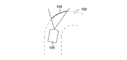
- the range 104 of the travel lane that can be captured by the camera is limited. Is done. Therefore, it is not possible to acquire sufficient information in front of the vehicle that is sufficient to identify necessary information about the travel lane and to normally execute the travel locus control. For this reason, when the radius of the travel lane is small, it is inevitable that the accuracy of the travel locus control is reduced, and when the range of the travel lane that can be imaged by the camera is greatly limited, the travel locus control must be stopped. .
- the above-mentioned problem is not limited to the case where the radius of the traveling lane is small.
- rain, splash, abrupt changes in ambient brightness such as the entrance of a tunnel, and a large vehicle in front of the vehicle This also occurs in a situation where normal imaging is hindered.
- the main object of the present invention is to prevent the deterioration of accuracy as much as possible even in a situation where sufficient information in front of the vehicle is not sufficient to identify the information of the driving lane by a camera that images the front of the vehicle.
- the running locus control is continued.
- the imaging means for imaging the surroundings of the vehicle the target steering angle of the steered wheels is calculated based on the imaging information obtained by the imaging means, and the steering angle of the steered wheels is controlled based on the target steering angle.
- a target steering angle of a steered wheel can be normally calculated based on imaging information in front of the vehicle.
- a vehicle trajectory control apparatus that calculates a target steering angle of a steered wheel based on imaging information acquired by changing at least one of an imaging direction and an imaging range of an imaging unit.
- the target steering angle of the steered wheel can be calculated based on the above. Therefore, compared to the case where at least one of the imaging direction and the imaging range is not changed, it is possible to expand the possibility of calculating the target steering angle of the steered wheel normally, thereby preventing the degradation of accuracy as much as possible and controlling the trajectory. Can continue.
- the imaging means for imaging the surroundings of the vehicle the target steering angle of the steered wheel is calculated based on image information obtained by the imaging means, and the steering angle of the steered wheel is controlled based on the target steering angle.
- the target steering angle of the steered wheels is normally calculated based on imaging information in front of the vehicle.
- a vehicle trajectory control device characterized in that when the vehicle cannot perform imaging, the side of the vehicle is imaged by the imaging means, and the arithmetic control device calculates a target steering angle of the steered wheel based on at least image information of the side of the vehicle.
- the target rudder angle of the steered wheel when the target rudder angle of the steered wheel cannot be normally calculated based on the imaging information in front of the vehicle, the target rudder angle of the steered wheel is calculated based on at least the image information on the side of the vehicle. can do. Therefore, it is possible to expand the possibility of calculating the target rudder angle of the steered wheel normally compared to the case where the side of the vehicle is not imaged, thereby preventing the deterioration of accuracy as much as possible and continuing the travel locus control. Can do.
- the imaging means includes a front imaging device that images the front of the vehicle, and a side imaging device that images at least one side of the left and right sides of the vehicle, and the arithmetic control device is a vehicle.
- the target rudder angle of the steered wheels can be normally calculated based on the image information ahead of the vehicle
- the target rudder angle of the steered wheels is calculated based on the image information ahead of the vehicle by the front image pickup device
- the target rudder angle of the steered wheel cannot be normally calculated based on the imaging information
- the target rudder angle of the steered wheel is calculated based on at least the side image pickup information of the vehicle by the side imaging device. Good.
- the target rudder angle of the steered wheel when the target rudder angle of the steered wheel can be normally calculated based on the imaging information in front of the vehicle, the imaging information in front of the vehicle is not required without requiring imaging information on the side of the vehicle.
- the target rudder angle of the steered wheel can be calculated.
- the target rudder angle of the steered wheel can be calculated based on at least image information on the side of the vehicle.
- the arithmetic and control unit calculates the target rudder angle of the steered wheels based on the imaging information in front of the vehicle by the front imaging device when the radius of the traveling locus of the vehicle is larger than the reference value.
- the target rudder angle of the steered wheels may be calculated based on the side image pickup information of the vehicle by the side image pickup device.
- the target steering angle of the steered wheel is calculated based on the imaging information in front of the vehicle without requiring imaging information on the side of the vehicle. Can do. Further, when the radius of the vehicle travel locus is equal to or less than the reference value, the target steering angle of the steered wheels is calculated based on the side image pickup information of the vehicle by the side image pickup device without requiring the image information ahead of the vehicle. Can do.
- the arithmetic and control unit estimates at least one parameter of the lateral deviation of the vehicle with respect to the traveling lane, the yaw angle of the vehicle with respect to the traveling lane, and the radius of the traveling lane based on the imaging information, and the estimated parameter is Based on this, the target rudder angle of the steered wheels may be calculated.
- the target rudder angle of the steered wheels can be calculated based on at least one parameter of the lateral deviation of the vehicle with respect to the travel lane, the yaw angle of the vehicle with respect to the travel lane, and the radius of the travel lane.
- the side imaging device images at least one side of the left side and the right side of the vehicle
- the arithmetic and control unit is spaced in the front-rear direction of the vehicle based on the side imaging information.
- the lateral deviation of the vehicle and the target lateral deviation of the vehicle are calculated based on the imaging information on the side, and the target rudder angle of the steered wheel is calculated based on at least the lateral deviation of the vehicle and the target lateral deviation of the vehicle. can do.
- the arithmetic and control unit estimates the radius of the traveling lane based on the imaging information on the side, calculates the target yaw angle of the vehicle based on the radius of the traveling lane, and calculates the lateral deviation of the vehicle and the vehicle
- the target rudder angle of the steered wheels may be calculated based on the deviation from the target lateral deviation, the deviation between the yaw angle of the vehicle and the target yaw angle of the vehicle, and the radius of the traveling lane.
- the deviation of the lateral deviation of the vehicle and the target lateral deviation of the vehicle, the deviation between the yaw angle of the vehicle and the target yaw angle of the vehicle, the radius of the traveling lane, The target rudder angle can be calculated with high accuracy.
- the side imaging device images one of the left side and the right side of the vehicle
- the arithmetic and control unit estimates the yaw angle of the vehicle at three times based on the running motion of the vehicle.
- Estimate the position of the vehicle in virtual Cartesian coordinates for three times based on the yaw angle of the vehicle and the running motion of the vehicle, and at the reference position of the vehicle based on the side imaging information for the three times Estimate the lateral deviation of the vehicle with respect to the traveling lane, estimate the turning radius of the traveling lane based on the lateral deviation of the vehicle at three times, the yaw angle of the vehicle and the position of the vehicle, and based on the radius of the traveling lane
- the target yaw angle of the vehicle is calculated, and the deviation between the lateral deviation of the vehicle and the target lateral deviation of the vehicle at the third time, and the vehicle yaw angle and the target yaw angle of the vehicle at the third time are calculated.
- the side imaging device images at least one of the left side and the right side of the vehicle
- the arithmetic and control unit is a travel lane at the reference position of the vehicle based on the side imaging information.
- the vehicle lateral deviation with respect to the vehicle lane is estimated, the vehicle lateral deviation and the travel lane width information are calculated based on at least one of the vehicle lateral deviation and the travel lane width information, and the vehicle lateral deviation and the vehicle target lateral deviation are calculated.
- the target rudder angle of the steered wheel may be calculated.
- the target steering angle of the steered wheels can be calculated based on the lateral deviation of the vehicle and the target lateral deviation of the vehicle without calculating the radius of the traveling lane, the yaw angle of the vehicle, and the target yaw angle of the vehicle. it can.
- the side imaging device includes a left side imaging device that images the left side of the vehicle and a right side imaging device that images the right side of the vehicle, and the arithmetic and control unit includes the left side imaging information and the right side imaging device.
- the lateral deviations of the left and right vehicles with respect to the traveling lane are estimated based on the image information of the vehicle, and the target lateral deviation of the vehicle with respect to the traveling lane is calculated based on the lateral deviation of the vehicle with respect to the left and right traveling lanes. It may be.
- the target lateral deviation of the vehicle with respect to the traveling lane can be calculated based on the lateral deviation of the vehicle with respect to the left and right traveling lanes.
- the side imaging device images one side of the left side and the right side of the vehicle
- the arithmetic and control unit is a front side spaced in the front-rear direction of the vehicle based on the side imaging information.
- One of the values is the target lateral deviation of the vehicle, and the target steering angle of the steered wheels is calculated based on the deviation between the lateral deviation of the vehicle and the target lateral deviation of the vehicle, and the deviation between the yaw angle of the vehicle and the target yaw angle of the vehicle. It may be like this.
- one of a value variably set based on the width of the traveling lane and a preset value is set as the vehicle target lateral deviation, and the deviation between the vehicle lateral deviation and the vehicle target lateral deviation, and the vehicle
- the target rudder angle of the steered wheels can be calculated based on the deviation between the yaw angle and the target yaw angle of the vehicle.
- the arithmetic and control unit controls the trajectory of calculating the target rudder angle of the steered wheels based on the imaging information in front of the vehicle by the front imaging device, and the imaging of the side of the vehicle by at least the side imaging device.
- the target steering angle of the steered wheel may be gradually changed when the travel trajectory control is switched between the travel trajectory control for calculating the target rudder angle of the steered wheel based on the information.
- the arithmetic and control unit calculates the first target rudder angle of the steered wheels based on the imaging information of the front of the vehicle by the front imaging device when the radius of the traveling locus of the vehicle is equal to or less than the reference value.
- the second target rudder angle of the steered wheels is calculated based on the side image pickup information of the vehicle by the side image pickup device, the driver's forward gaze distance is estimated based on the vehicle speed and the radius of the vehicle travel locus, and the front
- the contribution degree of the second target rudder angle is variably set higher than when the imageable distance of the front imaging device is long with respect to the front gaze distance.
- the target rudder angle of the steered wheel may be calculated based on the target rudder angle, the second target rudder angle, and the contribution degree.
- the contribution degree of the second target rudder angle is variably set according to the relationship between the front gaze distance and the imageable distance of the front image pickup device, and the first target rudder angle, the second target rudder angle, Based on the degree of contribution, the target rudder angle of the steered wheels can be calculated. Therefore, the contribution degree of the second target rudder angle is lowered when the imageable distance of the front imaging device is long with respect to the front gaze distance, and the second target rudder angle when the imageable distance of the front imaging device is short with respect to the front gaze distance.
- the target rudder angle of the steered wheel can be calculated with a higher degree of contribution.
- the imaging means includes a front imaging device that images the front of the vehicle, and a side imaging device that images at least one side of the left and right sides of the vehicle, and the arithmetic control device is a vehicle.
- the target rudder angle of the steered wheels can be normally calculated based on the image information ahead of the vehicle
- the target rudder angle of the steered wheels is calculated based on the image information ahead of the vehicle by the front image pickup device
- the imaging information is supplemented based on the imaging information on the side of the vehicle by the side imaging device, and the steering is performed based on the imaging information after the compensation.
- the target rudder angle of the wheel may be calculated.
- the imaging information is compensated based on the imaging information on the side of the vehicle by the side imaging device.
- the target steering angle of the steered wheels can be calculated based on the post-compensation imaging information.
- the arithmetic and control unit identifies the white line of the traveling lane based on the imaging information ahead of the vehicle by the front imaging device, and calculates the target steering angle of the steered wheel based on the information on the white line of the traveling lane.
- the information on the white line of the traveling lane specified based on the imaging information on the front is insufficient, the information on the white line of the traveling lane specified based on the imaging information on the side of the vehicle by the side imaging device.
- the information on the white line of the traveling lane may be compensated for at, and the target rudder angle of the steered wheels may be calculated based on the information on the white line of the traveling lane after compensation.
- the white line on the traveling lane specified based on the imaging information on the front side when there is insufficient information on the white line of the traveling lane specified based on the imaging information on the front side, the white line on the traveling lane specified based on the imaging information on the side of the vehicle by the side imaging device.
- the information on the white line of the traveling lane is supplemented by the information. Therefore, even when the information on the white line of the traveling lane specified based on the imaging information ahead is insufficient, the target rudder angle of the steered wheel can be calculated with high accuracy based on the information on the white line of the traveling lane after compensation. it can.
- the arithmetic and control unit determines the length of the white line of the traveling lane identified based on the imaging information on the front side and the traveling lane identified based on the imaging information on the side of the vehicle by the side imaging device.
- the control of the travel locus of the vehicle may be stopped.
- the vehicle has a lighting device that can change the irradiation direction or irradiation range, and the arithmetic control device temporarily lacks information on the white line of the traveling lane specified based on the imaging information ahead.
- the irradiation direction or the irradiation range of the lighting device may be changed so that the information on the white line of the specified travel lane increases.
- the illumination direction of the lighting device is increased so that the information on the white line of the travel lane specified increases even when the information on the white line of the travel lane specified based on the imaging information in front is temporarily insufficient.
- the information on the white line of the specified travel lane is increased by changing the irradiation range. Therefore, it is possible to reduce the possibility that the control of the travel locus of the vehicle is stopped due to the insufficient length of the white line of the travel lane specified as compared with the case where the illumination direction or illumination range of the lighting device is not changed. Can do.
- the arithmetic and control unit reduces the vehicle speed to reduce the vehicle speed when either the vehicle is likely to deviate from the traveling lane or the imaging accuracy of the imaging means is reduced.
- the control of the travel locus may be continued.
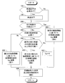
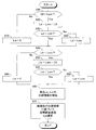
- FIG. 1 is a schematic configuration diagram illustrating a first embodiment of a vehicle travel locus control apparatus according to the present invention. It is explanatory drawing which shows the imaging procedure by the CCD camera for right sides, and the acquisition procedure of white line information in the state seen from the back of a vehicle. It is explanatory drawing which shows the imaging point by the CCD camera for right sides, and the acquisition procedure of white line information in the state seen from the upper direction of the vehicle. It is explanatory drawing which shows the point by which the white line information acquired by the imaging by the front CCD camera is supplemented with the white line information acquired by the imaging by the right side CCD camera when viewed from above the vehicle. It is a flowchart which shows the main routine of the driving
- FIG. 6 is a flowchart showing a calculation routine of a target lateral acceleration Gyt based on side image information that is executed in step 300 of the flowchart shown in FIG. 5.
- 6 is a flowchart showing a routine for calculating a target lateral acceleration Gyt based on forward imaging information executed in step 400 of the flowchart shown in FIG. 5.
- FIG. 6 is a flowchart showing a routine for calculating a target lateral acceleration Gyt based on forward and side imaging information executed in step 600 of the flowchart shown in FIG. 5.
- It is a flowchart which shows the target steering angle (delta) t calculation and steering angle control routine performed in step 7900 of the flowchart shown by FIG.
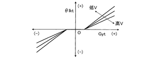
- FIG. 6 is a diagram showing a map for calculating a target steering angle ⁇ lkt for travel locus control based on a target lateral acceleration Gyt and a vehicle speed V of the vehicle. It is a figure which shows the map for calculating the correction coefficient Kv based on the vehicle speed based on the vehicle speed V.
- FIG. 6 is a diagram showing a map for calculating a target steering angle ⁇ lkt for travel locus control based on a target lateral acceleration Gyt and a vehicle speed V of the vehicle. It is a figure which shows the map for calculating the correction coefficient Kv based on the vehicle speed based on the vehicle speed V.
- FIG. 1 is a schematic configuration diagram showing a first embodiment of a vehicle travel locus control apparatus according to the present invention.
- a travel locus control device 10 is mounted on a vehicle 12 and has a front wheel steering control device 14.
- the front wheel steering control device 14 constitutes a steering control means capable of steering the front wheels irrespective of the driver's steering operation.
- the vehicle 12 is equipped with a braking force control device 16 that can individually control the braking force of each wheel regardless of the braking operation of the driver.
- 18FL and 18FR indicate left and right front wheels, which are the steering wheels of the vehicle 12, respectively, and 18RL and 18RR indicate left and right rear wheels, respectively.
- the left and right front wheels 18FL and 18FR which are the steering wheels, are rotated via a rack bar 24 and tie rods 26L and 26R by a rack and pinion type power steering device 22 driven in response to an operation of the steering wheel 20 by the driver. Steered.
- the steering wheel 20 is drivingly connected to a pinion shaft 36 of the power steering device 22 through an upper steering shaft 28, a steering angle varying device 30, a lower steering shaft 32, and a universal joint 34.
- the rudder angle varying device 30 is connected to the lower end of the upper steering shaft 28 on the housing 30A side and is connected to the upper end of the lower steering shaft 32 on the rotor 30B side.
- an electric motor 38 for driving the auxiliary steering is provided to the auxiliary steering.
- the steering angle varying device 30 rotationally drives the lower steering shaft 32 relative to the upper steering shaft 28 to drive auxiliary steering of the left and right front wheels 18FL and 18FR relative to the steering wheel 20.
- the steering angle varying device 30 is controlled by the steering control unit of the electronic control device 40.
- the power steering device 22 is a rack coaxial type electric power steering device, and includes an electric motor 42 and, for example, a ball screw type conversion mechanism 44 that converts the rotational torque of the electric motor 42 into a force in the reciprocating direction of the rack bar 24.
- the power steering device 22 is controlled by a steering assist torque control unit of the electronic control device 40 and generates a steering assist torque that drives the rack bar 24 relative to the housing 46.
- the steering assist torque reduces the steering burden on the driver, and assists the steering drive of the left and right front wheels by the steering angle varying device 30 as necessary.
- the steering angle varying device 30 cooperates with the power steering device 22 to change the relationship between the steering angles of the left and right front wheels with respect to the steering wheel 20 and to steer the front wheels regardless of the driver's steering operation. 14 main parts are formed.
- the structures of the power steering device 22 and the rudder angle varying device 30 do not constitute the gist of the present invention, and these devices may be any arbitrary known in the art as long as they each perform the above-described functions. It may be of the configuration of
- the hydraulic circuit 52 includes an oil reservoir, an oil pump, various valve devices, and the like, and the braking pressure of each wheel cylinder is normally driven according to the depression operation of the brake pedal 56 by the driver.
- the master cylinder 58 is controlled.
- the braking pressure of each wheel cylinder is individually controlled by the hydraulic circuit 52 being controlled by the braking force control unit of the electronic control unit 40 as necessary.
- the braking device 50 can individually control the braking force of each wheel regardless of the driver's braking operation, and functions as a main device of the braking force control device 16.
- the upper steering shaft 28 is provided with a steering angle sensor 62 that detects the rotation angle of the upper steering shaft as the steering angle ⁇ and a steering torque sensor 64 that detects the steering torque Ts, and indicates the steering angle ⁇ and the steering torque Ts.
- a signal is also input to the electronic control unit 40.
- the electronic control unit 40 receives a signal indicating the relative rotation angle ⁇ re of the rudder angle varying device 30 detected by the rotation angle sensor 66, that is, the relative rotation angle of the lower steering shaft 32 with respect to the upper steering shaft 28.
- a front CCD camera 68 for photographing the front of the vehicle 12 is provided in the front part of the passenger compartment of the vehicle 12, and a signal indicating image information in front of the vehicle 12 is a CCD camera. 60 to the electronic control unit 40.
- left and right side CCD cameras 70 and right side CCD cameras 72 for photographing the left and right sides of the vehicle 12 are provided on the left and right sides of the vehicle 12, respectively. Signals are input from the CCD cameras 70 and 72 to the electronic control unit 40.
- the electronic control unit 40 also receives a signal indicating the vehicle speed V detected by the vehicle speed sensor 74, a signal indicating the lateral acceleration Gy of the vehicle detected by the lateral acceleration sensor 76, and a vehicle yaw rate ⁇ detected by the yaw rate sensor 78.
- the signal shown is input. Further, a signal indicating a master cylinder pressure Pm detected by a pressure sensor not shown in FIG.
- Each of the above-described control units of the electronic control device 40 may include a CPU, a ROM, a RAM, and an input / output port device, which are connected to each other via a bidirectional common bus. Further, the steering angle sensor 62, the steering torque sensor 64, and the rotation angle sensor 66 detect the steering angle ⁇ , the steering torque Ts, and the relative rotation angle ⁇ re, respectively, with the case of steering or turning in the left turn direction of the vehicle as positive.
- the steering control unit of the electronic control device 40 performs traveling locus control, which is also called lane keep assist control (LKA control), based on image information in front of the vehicle 12 acquired by the forward CCD camera 68 at normal times. That is, the steering control unit identifies the traveling lane based on the image information ahead of the vehicle 12 acquired by the front CCD camera 68, and sets the target rudder angle ⁇ t of the left and right front wheels for causing the vehicle 12 to travel along the traveling lane.
- the rudder angle varying device 30 is controlled so that the rudder angle ⁇ of the front wheels becomes the target rudder angle ⁇ t.
- the steering control unit of the electronic control device 40 performs the alternative traveling locus control when the traveling locus control cannot be normally performed based on the image information in front of the vehicle 12 acquired by the forward CCD camera 68.
- the steering control unit identifies the traveling lane based on the side image information of the vehicle 12 acquired by the left side CCD camera 70 or the right side CCD camera 72.
- the steering control unit calculates a target pinion angle ⁇ t corresponding to the target rudder angle ⁇ t of the left and right front wheels for causing the vehicle 12 to travel along the travel lane, and the rudder angle is variable so that the angle of the pinion 36 becomes the target pinion angle ⁇ t.
- the apparatus 30 is controlled.
- the steering control unit of the electronic control unit 40 estimates the lateral deviation of the vehicle with respect to the traveling lane, the yaw angle of the vehicle with respect to the traveling lane, and the radius of the traveling lane in both the normal and alternative traveling locus control.
- the target steering angle of the steered wheel is calculated based on the parameter thus obtained.
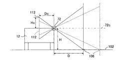
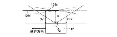
- FIG. 2 is an explanatory diagram showing how the right side CCD camera 72 captures the image and obtains white line information as seen from the rear of the vehicle.
- the height of the right side CCD camera 72 from the traveling lane 102 is H, and the horizontal distance between the right edge of the vehicle 12 and the white line 106 is D.
- the distance between the lens of the right-side CCD camera 72 and the imaging surface 108 is Dc, and the distance between the optical axis 110 of the right-side CCD camera 72 and the image 112 of the white line 106 on the imaging surface 108 is Hc. Between these distances, the following formula 1 is established from the similarity of figures.
- Hc: H Dc: D (1)
- the white line in the range exceeding the longitudinal length of the vehicle. 106 can be photographed and specified.
- the horizontal distances Dr1 and Dr2 between the right edge at the front end and the rear end of the vehicle 12 and the white line 106 can be obtained.
- the horizontal distances Dl1 and Dl2 between the left side edge and the white line at the front end and the rear end of the vehicle 12 can be similarly obtained.
- a white line which is photographed by the front CCD camera 68 and specified based on the imaging information is assumed to be 106f. Even when the length of the white line 106f is shorter than the length necessary for obtaining the radius of the traveling lane, the information of the white line 106s for compensation specified based on the imaging information photographed by the right-side CCD camera 72 is included. Thus, the information on the white line can be compensated and the required length of the white line can be secured.
- the control according to the flowchart shown in FIG. 5 is started by closing an ignition switch (not shown), and is repeatedly executed at predetermined time intervals.
- step 100 it is determined whether or not it is necessary to continue the travel locus control by reducing the vehicle speed.
- step 200 an affirmative determination is made.
- step 150 control proceeds to step 150. Note that when there is a possibility that the vehicle deviates from the travel lane or when the imaging accuracy of the CCD camera is lowered, it may be determined that it is necessary to reduce the vehicle speed and continue the travel locus control.
- step 150 the output of the engine not shown in FIG. 1 is reduced, and if necessary, the vehicle speed V is reduced by ⁇ V by operating the braking device.
- the vehicle speed decrease amount ⁇ V is variably set according to the vehicle speed so as to increase as the vehicle speed V increases.
- the vehicle speed decrease amount ⁇ V may be variably set so as to increase as the vehicle is more likely to deviate from the driving lane or as the degree of decrease in imaging accuracy of the CCD camera increases.
- step 200 it is determined whether or not the radius Rv of the travel locus is equal to or less than a preset reference value with the radius R of the travel lane calculated last time as the radius Rv of the travel locus.
- the target lateral acceleration Gyt of the vehicle is calculated based on the side imaging information in step 300 according to the flowchart shown in FIG. Proceed to When the navigation device is mounted on the vehicle, the turning radius Rv may be obtained based on information on the travel lane given by the navigation device.
- step 350 it is determined whether or not alternative trajectory control for calculating the target lateral acceleration Gyt of the vehicle is necessary based on the side image information. If a negative determination is made, the target lateral acceleration Gytf of the vehicle is calculated based on the forward imaging information in accordance with the flowchart shown in FIG. 7 in step 400. If an affirmative determination is made, control proceeds to step 500. move on.
- step 500 it is determined whether or not the white line of the forward traveling lane can be specified more than a preset minimum reference length based on the forward imaging information.
- the target lateral acceleration Gyt of the vehicle is set to 0 at step 550, and when an affirmative determination is made, control proceeds to step 600. It is also determined whether or not the white line of the side traveling lane can be specified more than a preset minimum reference length based on the side imaging information. If a negative determination is made, control is performed in step 550. May be modified to proceed to.
- step 600 the target lateral acceleration Gyt of the vehicle is calculated based on the front and side imaging information according to the flowchart shown in FIG.
- step 300, 400, 550 or 600 the control proceeds to step 900, where the target steering angle ⁇ t of the front wheels is calculated according to the flowchart shown in FIG. 9, and based on the target steering angle ⁇ t.
- the steering angle ⁇ of the front wheels is controlled.
- step 310 the white line of the traveling lane is specified based on the left and right side imaging information, and the radii Rsl and Rsr of the left and right white lines are calculated based on the specified white line. Then, the radius Rs of the travel lane is calculated as an average value of the radii Rsl and Rsr. The radius Rs of the travel lane may be calculated based on one of the radii Rsl and Rsr.
- the front reference position and the rear reference position of the vehicle are the front end and the rear end of the vehicle, respectively, and the side edges of the front end and the rear end of the vehicle 12 in the lateral direction of the vehicle as shown in FIG. And Dr1 and Dr2 are calculated.
- step 320 the distance between the front end and the rear end of the vehicle is L, and the yaw angle ⁇ s of the vehicle with respect to the travel lane is calculated according to the following equation 3 based on the lateral deviations Dr1 and Dr2 on the right side.
- the yaw angle ⁇ s of the vehicle may be calculated according to the following equation 4 based on the left lateral deviations Dl1 and Dl2, or may be a simple average value or a weighted average value of the values calculated according to equations 3 and 4. .
- step 325 assuming that the width of the vehicle is W, the target lateral deviation Dst of the vehicle with respect to the center of the traveling lane is calculated according to the following equation 5 based on the lateral deviations Dr1, Dr2 on the right side and the yaw angle ⁇ s of the vehicle.
- the target lateral deviation Dst is a target distance between the right edge of the vehicle and the right edge of the traveling lane (right white line) necessary for the center of the vehicle to travel along the center of the traveling lane, or the left edge of the vehicle and the left side of the traveling lane. This is the target distance from the edge (left white line).
- step 360 the target yaw angle ⁇ st of the vehicle is calculated as a minute value that is larger as the radius Rs of the traveling lane calculated in step 310 is the same as the radius Rs.
- step 365 the average value of the lateral deviations Dr1 and Dr2 on the right side of the vehicle is calculated as the actual lateral deviation Ds on the right side of the vehicle, and Ksr, Ksy and Ksh are respectively set as positive coefficients set in advance as follows.
- step 370 it is determined whether or not the correction coefficient Ks is 1, that is, the target lateral acceleration Gyts of the vehicle based on the side imaging information is calculated from the calculation mode of the target lateral acceleration Gytf of the vehicle based on the imaging information on the front side. It is determined whether or not the transition to the calculation mode has been completed.
- the target lateral acceleration Gyt of the vehicle is set to the target lateral acceleration Gyts of the vehicle based on the side imaging information, and when a negative determination is made, control proceeds to step 380. .
- the target lateral acceleration Gytf of the vehicle is calculated based on the forward imaging information.
- the radius of the traveling lane, the lateral deviation of the vehicle, the yaw angle of the vehicle, the target lateral deviation of the vehicle, and the target yaw angle of the vehicle are calculated.
- the target lateral acceleration Gytf is calculated.
- the target lateral acceleration Gytf may be calculated in other ways.
- correction coefficients Kf and Ks are calculated from the map shown in FIG. 15 based on the elapsed time tfs from the time when the determination in step 200 changes from negative determination to positive determination. As shown in FIG. 15, the correction coefficient Kf gradually changes from 1 to 0 as the elapsed time tfs increases, and the correction coefficient Ks gradually changes from 0 to 1 as the elapsed time tfs increases, and the elapsed time tfs. Regardless of whether the sum of the correction coefficients Kf and Ks is 1.
- step 390 the target lateral acceleration Gyt of the vehicle is calculated according to the following equation 7.
- Gyt KfGytf + KsGyts (7)
- step 410 the target lateral acceleration Gytf of the vehicle is calculated based on the forward imaging information as in step 380 described above.
- step 415 it is determined whether or not the correction coefficient Kf is 1, that is, the target lateral acceleration Gytf of the vehicle based on the preceding imaging information is calculated from the calculation mode of the target lateral acceleration Gyts of the vehicle based on the side imaging information. It is determined whether or not the transition to the calculation mode has been completed. If an affirmative determination is made, the target lateral acceleration Gyt of the vehicle is set to the target lateral acceleration Gytf of the vehicle based on the forward imaging information in step 420. If a negative determination is made, control proceeds to step 425.
- the correction coefficient Kf is 1, that is, the target lateral acceleration Gytf of the vehicle based on the preceding imaging information is calculated from the calculation mode of the target lateral acceleration Gyts of the vehicle based on the side imaging information. It is determined whether or not the transition to the calculation mode has been completed. If an affirmative determination is made, the target lateral acceleration Gyt of the vehicle is set to the target lateral acceleration Gytf of the vehicle based on the forward imaging information in step
- step 425 the target lateral acceleration Gyts of the vehicle based on the side imaging information is calculated in the same manner as 310 to 365 described above.
- correction coefficients Kf and Ks are calculated from the map shown in FIG. 16 based on the elapsed time tsf from the time when the determination in step 200 changes from positive determination to negative determination.
- the correction coefficient Kf gradually changes from 0 to 1 as the elapsed time tsf increases, and the correction coefficient Ks gradually changes from 1 to 0 as the elapsed time tsf increases. Gradually changes from 0 to 1 as the elapsed time tsf increases, and the sum of the correction coefficients Kf and Ks is 1 regardless of the elapsed time tsf.
- step 435 the target lateral acceleration Gyt of the vehicle is calculated according to equation 4 in the same manner as in step 390 above.
- step 600 the target lateral acceleration Gyt calculation routine based on the forward and side imaging information executed in step 600 will be described with reference to the flowchart shown in FIG.
- the minimum length required for vehicle trajectory control is Lmin, and the length Lfl of the left white line specified based on the forward imaging information is less than the required length Lmin.
- a determination is made whether or not there is. When a negative determination is made, the length Lsl that needs to be compensated with the left white line specified based on the side image pickup information at step 615 is set to 0, and when an affirmative determination is made, step 620 is performed.
- the required length Lsl is set to Lmin ⁇ Lfl.
- step 625 it is determined whether or not the length Lsl that needs to be compensated is less than Lsla, where Lsla is the length of the left white line specified based on the side imaging information.
- Lsla is the length of the left white line specified based on the side imaging information.
- step 640 it is determined whether or not the length Lfr of the right white line specified based on the forward imaging information is less than the required length Lmin.
- the length Lsr that needs to be compensated by the right white line specified based on the side image pickup information is set to 0 at step 645, and when an affirmative determination is made, step 650 is set.
- the required length Lsr is set to Lmin-Lfr.
- step 655 it is determined whether or not the length Lsr that needs to be compensated is less than Lsra, with the length of the white line on the right specified based on the side imaging information as Lsra. If an affirmative determination is made, control proceeds to step 665. If an affirmative determination is made, the required length Lsr is set to Lsra in step 660.
- step 665 the left and right white lines are filled with white lines of the required lengths Lsl and Lsr, respectively.
- the target lateral acceleration Gytf in step 410 is based on the left and right white lines after compensation.
- the target lateral acceleration Gyt of the vehicle is calculated based on the front and side imaging information in the same manner as the above calculation.
- step 900 a calculation routine of the target pinion angle ⁇ t and a control routine for the steering angle ⁇ of the front wheels based on the target pinion angle ⁇ t executed in step 900 will be described with reference to the flowchart shown in FIG.
- step 910 based on the target lateral acceleration Gyt and the vehicle speed V of the vehicle, the target steering angle ⁇ lkt for travel locus control is calculated from the map shown in FIG.
- step 920 based on the vehicle speed V, a correction coefficient Kv based on the vehicle speed is calculated from the map indicated by the solid line in FIG. In FIG. 18, the broken line indicates the correction coefficient Kv based on the vehicle speed when the travel locus control is not performed.
- step 940 when the steering input is given, the parameter for preventing the steering angle variable device 30 from excessively turning the front wheel excessively is ⁇ t, and the pinion angle ⁇ is the final target pinion angle.
- the steering angle varying device 30 is controlled so as to be ⁇ t + ⁇ t, whereby the steering angle ⁇ of the left and right front wheels is controlled to the target steering angle ⁇ t corresponding to the target pinion angle ⁇ lkt.
- the travel locus control can be continued based on the above. Therefore, it is possible to extend the possibility of normally executing the traveling locus control as compared with the case where the side of the vehicle is not imaged, and thereby it is possible to continue the traveling locus control while preventing a decrease in accuracy as much as possible.
- step 400 In the situation where the running locus control is continued based on the side imaging information, when the running locus control can be normally performed based on the imaging information in front of the vehicle, steps 200 and 350 are performed. In this case, a negative determination is made, and control proceeds to step 400. Therefore, although the traveling locus control can be normally performed based on the imaging information in front of the vehicle, the traveling locus control based on the imaging information on the side is not continued unnecessarily.
- the distance on the vehicle front side of the traveling lane specified in the traveling locus control based on the imaging information on the side is based on the distance on the vehicle front side of the traveling lane identified in the traveling locus control based on the imaging information on the front. Also short. However, it is possible to increase the possibility that the vehicle is surely traveled along the travel lane as compared with the case where the travel locus control based on the imaging information ahead is stopped.
- the control mode in which the target lateral acceleration Gyt of the vehicle is calculated based on the imaging information on the front side and the control mode in which the target lateral acceleration Gyt of the vehicle is calculated based on the side imaging information A sudden change in the target lateral acceleration Gyt when changing between the two can be prevented. Accordingly, it is possible to prevent the traveling state of the vehicle from changing suddenly due to the sudden change in the target lateral acceleration Gyt accompanying the change between the control mode and the control mode. This effect can also be obtained in other embodiments described later.
- step 500 when an affirmative determination is made in step 350, the determination in step 500 is performed. Then, when it is determined in step 500 that the white line of the forward traveling lane can be specified more than a preset minimum reference length based on the forward imaging information, step 600 is executed.
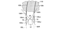
- FIG. 20 there is an obstacle 110 that obstructs photographing by the front CCD camera 68 like a mist in front of the vehicle, and only the left and right white lines 106l and 106r to be imaged are imaged by the front CCD camera 68. Indicates a situation where cannot.
- 106 fl and 106 fr indicate white lines that can be captured by the front CCD camera 68
- 106 sl and 106 sl indicate white lines that are captured by the side CCD cameras 70 and 72.
- the white lines on the left and right sides are respectively compensated with the white lines of the required lengths Lsl and Lsr by the control in step 600. That is, the left and right white lines are compensated by the white lines 106sls and 106srs of the required lengths Lsl and Lsr, respectively, of the white lines 106sl and 106sr. Therefore, even when there is an obstacle 110 that obstructs photographing by the front CCD camera 68, the traveling locus control can be continued without stopping. This effect can also be obtained in the second to fourth embodiments described later.
- step 600 is not executed.
- the travel locus control is stopped. Therefore, when the length of the white line specified based on the forward imaging information is less than the required length Lmin, the travel locus control is stopped. Accordingly, the running locus control is prevented from being continued in a situation where normal running locus control cannot be continued even if the white line information captured by the side CCD cameras 70 and 72 is compensated. be able to. This effect can also be obtained in the second to fourth embodiments described later.
- the radius Rs of the traveling lane, the lateral deviation Ds of the vehicle, the yaw angle ⁇ s of the vehicle, the target lateral deviation Dst of the vehicle which are specified based on the side imaging information in Step 300.
- the target yaw angle ⁇ st of the vehicle is calculated, and the target lateral acceleration Gyt is calculated based on these. Therefore, for example, when the target lateral acceleration Gyt is calculated based on the lateral deviation Ds of the vehicle and the target lateral deviation Dst, when the radius Rs of the traveling lane is not taken into consideration, the vehicle posture is maintained in a good posture.
- the vehicle can preferably travel along the traveling lane. This effect is also obtained in the second embodiment described later.
- FIG. 10 is a flowchart showing a calculation routine of the target lateral acceleration Gyt based on the side imaging information in the second embodiment of the vehicle travel locus control apparatus according to the present invention.
- the same steps as those shown in FIG. 6 are assigned the same step numbers as those shown in FIG. The same applies to other embodiments described later.
- steps 330 to 345 are executed in a manner different from that of the first embodiment, but steps 360 to 390 are executed in the same manner as the first embodiment. Is done.
- the distance Dl (t) between the left side edge of the front end of the vehicle and the left side edge of the traveling lane is calculated.
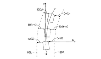
- the Cartesian coordinates are set with the vehicle's forward reference position as the origin, the lateral direction of the vehicle as the X axis, and the front of the vehicle as the axis when the vehicle starts running or when the vehicle transitions from the straight traveling state to the turning state.
- ⁇ is the slip angle of the vehicle
- the coordinates (X0, Y0) of the front reference position of the vehicle at the start of calculation are used to calculate the front reference position (the center of the vehicle) of the vehicle at each time according to the following formulas 9 and 10.
- Coordinates (Xt, Yt) are calculated.
- the inclination angle of the line 112 in the longitudinal direction of the vehicle 12 in the orthogonal coordinates at the start of calculation is ⁇ in0
- the longitudinal direction of the vehicle 12 in the orthogonal coordinates at the current time t t according to the following equation 11
- the inclination angle ⁇ int of the line 112 is calculated.
- the target slip angle ⁇ of the vehicle may be calculated as follows, for example.
- the deviation of the lateral acceleration that is, the lateral slip acceleration Vyd of the vehicle is calculated as the deviation Gy ⁇ V ⁇ ⁇ of the product V ⁇ ⁇ t of the lateral acceleration Gy of the vehicle and the vehicle speed V and the yaw rate ⁇ of the vehicle.
- the coordinates (Xt, Yt) of the vehicle front reference position (vehicle center), the inclination angle ⁇ int, and the vehicle in the lateral direction of the vehicle are calculated based on the distances Dr (0), Dr (tn), and Dr (t) between the side edge of the front end of the vehicle and the point P on the right side edge of the traveling lane.
- the travel locus control can be continued based on the above.
- the lateral distances Dl (t) and Dr (t) may be lateral distances only at the reference position in front of the vehicle, and both forward and backward reference There is no need to determine the lateral distance at the position.
- the three coordinates (X (0), Y (0)), (X (tn), Y (tn)), (X (t), Y (t) of the point P are used.
- the simultaneous equation is set by substituting the value of)) into the following equation (18). Then, by solving the simultaneous equations, the radius Rs of the traveling lane is calculated. However, the radius Rs of the traveling lane may be calculated based on the three coordinates of the point Q on the left white line 80L.
- the radius Rs of the traveling lane may be calculated as a simple average value or a weighted average value of the radius Rsr of the traveling lane based on the three coordinates of the point P and the radius Rsl of the traveling lane based on the three coordinates of the point Q. .
- the tangent line 114 with respect to the white line 80R on the right side passing through the point P is obtained, and the yaw angle ⁇ t of the vehicle is calculated as the angle formed by the line 112 in the front-rear direction and the tangent line 114.
- the tangent line 116 to the left white line 80L passing through the point Q may be obtained, and the yaw angle ⁇ t of the vehicle may be calculated as an angle formed by the line 112 in the front-rear direction and the tangent line 116.
- the vehicle yaw angle ⁇ t may be calculated as a simple average value or a weighted average value of the vehicle yaw angle ⁇ tr based on the tangent line 114 and the vehicle yaw angle ⁇ tl based on the tangent line 116.
- FIG. 11 is a flowchart showing a calculation routine of the target lateral acceleration Gyt based on the side imaging information in the second embodiment of the vehicle travel locus control apparatus according to the present invention.
- the same step number as that shown in FIG. 10 is assigned to the same step as that shown in FIG.
- steps 330 to 340 are executed in the same manner as in the second embodiment, but steps 350 and 365a are executed instead of steps 345 and 365, respectively.
- steps 360, 370 to 390 are executed in the same manner as in the first embodiment.
- the target lateral deviations Drst and Dlst of the vehicle with respect to the center of the traveling lane according to the same equation as the equation 19 above. Is calculated.
- the target lateral deviation Dst of the vehicle based on the center of the traveling lane is calculated according to the following equation 20.
- Dst (Drst + Dlst) / 2 (20)
- step 365a the target lateral acceleration Gyts of the vehicle based on the side imaging information is calculated according to the following equation (21).
- Gyts Ksy (Dst ⁇ Ds) (21)
- the traveling locus control can be normally performed based on the imaging information in front of the vehicle, the lateral imaging information is not required to calculate the radius Rs of the traveling lane. Based on this, the traveling locus control can be continued.
- the target lateral acceleration Gyts of the vehicle is calculated without considering the yaw angle of the vehicle.
- the target lateral acceleration Gyts of the vehicle may be calculated according to the following equation 24, as in the case of the fourth embodiment described later.
- FIG. 12 is a flowchart showing a calculation routine of the target lateral acceleration Gyt based on the side imaging information in the fourth embodiment of the vehicle travel locus control apparatus according to the present invention.
- step 310 is not executed, and steps 355 and 365b are executed instead of steps 325 and 365, respectively. Steps 360, 370 to 390 are executed in the same manner as in the first embodiment.
- step 355 when the left-side CCD camera 70 and the right-side CCD camera 72 are used, according to the same formula as the formula 19 of the first embodiment, A target lateral deviation Dst is calculated.
- the target lateral deviation Dst of the vehicle is calculated according to the following equation 23 as a value represented by ⁇ Xr below equation 22. The same applies when only the right-side CCD camera 72 is used.
- Xr is the width of the traveling lane and is uniquely set in advance.
- step 365b the target lateral acceleration Gyts of the vehicle based on the side imaging information is calculated according to the following equation 24.
- Gyts Ksy (Dst ⁇ Ds) + Ksh ( ⁇ st ⁇ s) (24)
- the radius of the travel lane Rs can be adjusted even when the travel locus control cannot be normally performed based on the imaging information in front of the vehicle.
- the traveling locus control can be continued based on the imaging information on the side without requiring calculation.
- the side imaging information may be either the left side or the right side, so that even if one of the left side CCD camera 70 and the right side CCD camera 72 becomes incapable of imaging, it can run. Trajectory control can be continued.
- FIG. 13 is a flowchart showing the main part of the main routine of the travel locus control in the fifth embodiment of the vehicle travel locus control apparatus according to the present invention
- FIG. 14 is the side image pickup information in the fifth embodiment.
- 5 is a flowchart showing a calculation routine of a target lateral acceleration Gyts based on the above.
- steps 100 to 550 are executed in the same manner as in the first embodiment described above. However, when an affirmative determination is made in step 500, the control proceeds to step 700. move on.
- step 700 the target lateral acceleration Gytf of the vehicle is calculated based on the forward imaging information, as in step 380 of the flowchart shown in FIG. 6 and step 410 of the flowchart shown in FIG.
- step 750 the target lateral acceleration Gyts of the vehicle is calculated based on the side imaging information according to the flowchart shown in FIG. Note that steps 310 to 365 in the flowchart shown in FIG. 14 are the same as steps 310 to 365 in the flowchart shown in FIG. 6 in the first embodiment described above.
- step 800 the driver's forward gazing distance Lv is estimated based on the vehicle speed V, the lane radius Rs, and the lane gradient, and the white line ahead of the vehicle can be recognized by the front CCD camera.
- Lfd is obtained.
- the correction coefficient Kd is increased.
- the correction coefficient Kd is decreased from 0.
- the correction coefficient Kd is calculated as a value larger and smaller than 1.
- the target lateral acceleration Gyt of the vehicle is calculated as a linear sum of the target lateral accelerations Gytf and Gyts based on the correction coefficient Kd according to the following equation 25.
- Gyt (1-Kd) Gytf + KdGyts (25)
- the traveling locus control is continued based on the imaging information on the front and side.
- the traveling locus control can be continued.
- the correction coefficient Kd is calculated in step 800, and the target lateral acceleration Gyt of the vehicle is calculated as a linear sum of the target lateral accelerations Gytf and Gyts based on the correction coefficient Kd according to Equation 26. .
- the correction coefficient Kd is larger when the distance Lfd is shorter than the forward gaze distance Lv, and conversely, when the distance Lfd is longer than the front gaze distance Lv, the correction coefficient Kd is smaller. Is variably set.
- the traveling locus control can be continued by increasing the contribution degree of the imaging information. Therefore, the traveling locus control can be appropriately continued according to the magnitude relationship between the forward gaze distance Lv and the distance Lfd as compared with the case where the correction coefficient Kd is not variably set.
- the imaging means includes the front CCD camera 68, the left side CCD camera 70, and the right side CCD camera 72.
- the imaging means may be one or two imaging devices that change at least one of the imaging direction and the imaging angle.
- the front and rear reference positions of the vehicle are the front end and the rear end of the vehicle.
- at least one of the front and rear reference positions may be set to a position between the front end and the rear end of the vehicle, and the front reference position may be set to the front of the vehicle front end.
- the reference position may be set behind the rear end of the vehicle.
- step 500 when a negative determination is made in step 500, the control proceeds to step 550 and the travel locus control is stopped.
- the irradiation direction of the headlamp or fog lamp is changed, and the determination in step 500 may be executed again.
- the reference of the target lateral deviation of the vehicle is the center of the traveling lane, but may be the right or left side edge of the traveling lane. It may be variably set according to the curve direction of the traveling lane so as to be the inner side edge.
- steps 500 and 600 may be omitted.
Landscapes
- Engineering & Computer Science (AREA)
- Transportation (AREA)
- Mechanical Engineering (AREA)
- Automation & Control Theory (AREA)
- Chemical & Material Sciences (AREA)
- Combustion & Propulsion (AREA)
- Physics & Mathematics (AREA)
- Mathematical Physics (AREA)
- Steering Control In Accordance With Driving Conditions (AREA)
- Power Steering Mechanism (AREA)
- Control Of Position, Course, Altitude, Or Attitude Of Moving Bodies (AREA)
Priority Applications (6)
| Application Number | Priority Date | Filing Date | Title |
|---|---|---|---|
| DE112011105821.7T DE112011105821B4 (de) | 2011-11-08 | 2011-11-08 | Fahrzeugfahrspursteuervorrichtung |
| PCT/JP2011/075766 WO2013069099A1 (ja) | 2011-11-08 | 2011-11-08 | 車両の走行軌跡制御装置 |
| JP2013542739A JP5747998B2 (ja) | 2011-11-08 | 2011-11-08 | 車両の走行軌跡制御装置 |
| CN201180074737.2A CN103917432B (zh) | 2011-11-08 | 2011-11-08 | 车辆的行驶轨迹控制装置 |
| IN3198DEN2014 IN2014DN03198A (enExample) | 2011-11-08 | 2011-11-08 | |
| US14/351,303 US9168953B2 (en) | 2011-11-08 | 2011-11-08 | Vehicle travel track control device |
Applications Claiming Priority (1)
| Application Number | Priority Date | Filing Date | Title |
|---|---|---|---|
| PCT/JP2011/075766 WO2013069099A1 (ja) | 2011-11-08 | 2011-11-08 | 車両の走行軌跡制御装置 |
Publications (1)
| Publication Number | Publication Date |
|---|---|
| WO2013069099A1 true WO2013069099A1 (ja) | 2013-05-16 |
Family
ID=48288686
Family Applications (1)
| Application Number | Title | Priority Date | Filing Date |
|---|---|---|---|
| PCT/JP2011/075766 Ceased WO2013069099A1 (ja) | 2011-11-08 | 2011-11-08 | 車両の走行軌跡制御装置 |
Country Status (6)
| Country | Link |
|---|---|
| US (1) | US9168953B2 (enExample) |
| JP (1) | JP5747998B2 (enExample) |
| CN (1) | CN103917432B (enExample) |
| DE (1) | DE112011105821B4 (enExample) |
| IN (1) | IN2014DN03198A (enExample) |
| WO (1) | WO2013069099A1 (enExample) |
Cited By (5)
| Publication number | Priority date | Publication date | Assignee | Title |
|---|---|---|---|---|
| KR20160064275A (ko) * | 2014-11-27 | 2016-06-08 | 연세대학교 산학협력단 | 차량 위치 인식 장치 및 방법 |
| JP2018012424A (ja) * | 2016-07-21 | 2018-01-25 | トヨタ自動車株式会社 | 車両用運転支援装置 |
| KR20190100855A (ko) * | 2018-02-07 | 2019-08-29 | 바이두 유에스에이 엘엘씨 | 자율 주행 차량을 위한 자기 위치 측정 방법, 시스템 및 기계 판독 가능한 매체 |
| CN115599875A (zh) * | 2022-10-24 | 2023-01-13 | 西北工业大学(Cn) | 一种轨迹异常检测方法、系统及产品 |
| US11751112B2 (en) | 2017-03-24 | 2023-09-05 | Huawei Technologies Co., Ltd. | Handover method and device |
Families Citing this family (38)
| Publication number | Priority date | Publication date | Assignee | Title |
|---|---|---|---|---|
| CN104442814B (zh) * | 2014-10-31 | 2016-07-06 | 重庆长安汽车股份有限公司 | 基于偏差预测算法的车道保持及自动对中系统和方法 |
| DE102014226764A1 (de) * | 2014-12-22 | 2016-06-23 | Robert Bosch Gmbh | Verfahren und Vorrichtung zum Führen eines Fahrzeugs auf einer Fahrspur |
| JP6470039B2 (ja) * | 2014-12-26 | 2019-02-13 | 日立オートモティブシステムズ株式会社 | 車両制御システム |
| DE102015203270A1 (de) * | 2015-02-24 | 2016-08-25 | Robert Bosch Gmbh | Verfahren und Vorrichtung zum Anpassen einer Fahrzeuggeschwindigkeit für ein Fahrzeug |
| CN104773202B (zh) * | 2015-03-04 | 2017-12-12 | 郑州机械研究所 | 汽车、单轮组/双轮组无轨列车及其循迹转向控制方法 |
| EP3109844B1 (en) * | 2015-06-23 | 2023-11-22 | Volvo Car Corporation | Object detecting arrangement |
| JP6446731B2 (ja) * | 2015-07-15 | 2019-01-09 | 本田技研工業株式会社 | 車両制御装置、車両制御方法、および車両制御プログラム |
| EP3434545B1 (en) * | 2016-03-24 | 2021-03-10 | Nissan Motor Co., Ltd. | Course estimation method and course estimation device |
| JP6583183B2 (ja) * | 2016-08-04 | 2019-10-02 | トヨタ自動車株式会社 | 車両制御装置 |
| DE102016216157A1 (de) * | 2016-08-29 | 2018-03-01 | Audi Ag | Verfahren zum Betrieb eines Kraftfahrzeugs |
| CA3036337A1 (en) * | 2016-09-09 | 2018-03-15 | Nissan Motor Co., Ltd. | Vehicle travel control method and travel control device |
| JP6569647B2 (ja) * | 2016-11-11 | 2019-09-04 | トヨタ自動車株式会社 | 車両の車線逸脱防止装置 |
| WO2018123640A1 (ja) * | 2016-12-26 | 2018-07-05 | 日立オートモティブシステムズ株式会社 | 撮像装置 |
| US20200114959A1 (en) * | 2017-02-17 | 2020-04-16 | Thyssenkrupp Presta Ag | Vehicle lateral motion control |
| FR3066985B1 (fr) * | 2017-06-06 | 2020-10-30 | Renault Sas | Dispositif d'assistance a la conduite d'un vehicule automobile dans une voie de circulation |
| JP6642522B2 (ja) * | 2017-06-06 | 2020-02-05 | トヨタ自動車株式会社 | 車線変更支援装置 |
| SE541795C2 (en) * | 2017-09-22 | 2019-12-17 | Sentient Ip Ab | Method and system for controlling vehicle lane holding |
| CN110276985B (zh) * | 2018-03-16 | 2020-12-15 | 华为技术有限公司 | 自动驾驶安全评估方法、装置和系统 |
| CN108820043B (zh) * | 2018-06-12 | 2021-06-01 | 上海工程技术大学 | 一种基于双侧轮速的汽车转向自动提醒方法及装置 |
| JP7147546B2 (ja) * | 2018-12-25 | 2022-10-05 | トヨタ自動車株式会社 | 車両のスリップ角推定装置 |
| KR102034316B1 (ko) * | 2019-01-29 | 2019-11-08 | 주식회사 만도 | 차량 위치 보정 시스템 및 방법, 그리고 카메라 |
| CN110262509B (zh) * | 2019-07-10 | 2022-06-28 | 百度在线网络技术(北京)有限公司 | 车辆自动驾驶方法和装置 |
| CN111645756B (zh) * | 2020-05-29 | 2021-10-08 | 摩登汽车有限公司 | 转向控制方法 |
| JP7235015B2 (ja) | 2020-07-17 | 2023-03-08 | トヨタ自動車株式会社 | 自動操舵システム |
| JP7719596B2 (ja) * | 2020-10-05 | 2025-08-06 | 株式会社Subaru | 車両の車線逸脱抑制制御装置 |
| JP7620266B2 (ja) | 2022-03-03 | 2025-01-23 | トヨタ自動車株式会社 | 車両制御システム |
| CN115092134B (zh) * | 2022-06-29 | 2024-08-16 | 长春一汽富晟集团有限公司 | 一种车辆车道居中保持系统及方法 |
| JP2024030217A (ja) | 2022-08-24 | 2024-03-07 | トヨタ自動車株式会社 | 車線逸脱防止装置 |
| JP2024032082A (ja) | 2022-08-29 | 2024-03-12 | トヨタ自動車株式会社 | 車線逸脱防止装置 |
| JP7718366B2 (ja) | 2022-09-26 | 2025-08-05 | トヨタ自動車株式会社 | 運転支援システム |
| JP7740190B2 (ja) | 2022-10-06 | 2025-09-17 | トヨタ自動車株式会社 | 車両制御装置 |
| JP7787498B2 (ja) | 2022-10-19 | 2025-12-17 | トヨタ自動車株式会社 | 車両の制御装置 |
| JP2024082331A (ja) | 2022-12-08 | 2024-06-20 | トヨタ自動車株式会社 | 車両制御装置 |
| JP2024101711A (ja) * | 2023-01-18 | 2024-07-30 | トヨタ自動車株式会社 | 運転支援装置および該運転支援装置を備えた運転支援システム |
| JP2024104067A (ja) | 2023-01-23 | 2024-08-02 | トヨタ自動車株式会社 | 車両制御装置 |
| JP2024148245A (ja) | 2023-04-05 | 2024-10-18 | トヨタ自動車株式会社 | 車両運転支援装置、車両運転支援方法及び車両運転支援プログラム |
| JP2024153273A (ja) | 2023-04-17 | 2024-10-29 | トヨタ自動車株式会社 | 車両制御装置、車両制御方法、及び車両制御プログラム |
| JP2025033405A (ja) | 2023-08-29 | 2025-03-13 | トヨタ自動車株式会社 | 車両制御装置 |
Citations (10)
| Publication number | Priority date | Publication date | Assignee | Title |
|---|---|---|---|---|
| JPH04283806A (ja) * | 1991-03-13 | 1992-10-08 | Nissan Motor Co Ltd | 自律走行車両 |
| JPH1031799A (ja) * | 1996-07-15 | 1998-02-03 | Toyota Motor Corp | 自動走行制御装置 |
| JP2001022444A (ja) * | 1999-07-05 | 2001-01-26 | Honda Motor Co Ltd | 車両用操舵制御装置 |
| JP2001283390A (ja) * | 2000-03-30 | 2001-10-12 | Honda Motor Co Ltd | 車両の周囲認識装置 |
| JP2008250904A (ja) * | 2007-03-30 | 2008-10-16 | Toyota Motor Corp | 車線区分線情報検出装置、走行車線維持装置、車線区分線認識方法 |
| JP2009018626A (ja) * | 2007-07-10 | 2009-01-29 | Toyota Motor Corp | 操舵制御装置 |
| JP2010002953A (ja) * | 2008-06-18 | 2010-01-07 | Mazda Motor Corp | 車両の車線逸脱警報装置 |
| JP2010069922A (ja) * | 2008-09-16 | 2010-04-02 | Toyota Motor Corp | 車線認識装置 |
| JP2010069921A (ja) * | 2008-09-16 | 2010-04-02 | Toyota Motor Corp | 車線認識装置 |
| JP2010154304A (ja) * | 2008-12-25 | 2010-07-08 | Zhencheng Hu | 移動体カメラシステム及び駆動方法 |
Family Cites Families (14)
| Publication number | Priority date | Publication date | Assignee | Title |
|---|---|---|---|---|
| JP2002109694A (ja) | 2000-09-29 | 2002-04-12 | Mitsubishi Motors Corp | 運転支援システム |
| JP3823924B2 (ja) * | 2003-01-31 | 2006-09-20 | 日産自動車株式会社 | 車両挙動制御装置 |
| JP3870911B2 (ja) * | 2003-02-10 | 2007-01-24 | 日産自動車株式会社 | 車線逸脱防止装置 |
| CN100473138C (zh) * | 2003-04-02 | 2009-03-25 | 松下电器产业株式会社 | 数据再生装置、视频显示装置和使用它们的软件更新系统 |
| US7720580B2 (en) * | 2004-12-23 | 2010-05-18 | Donnelly Corporation | Object detection system for vehicle |
| GB0516403D0 (en) * | 2005-08-10 | 2005-09-14 | Trw Ltd | Method and apparatus for determining motion of a vehicle |
| JP2007091025A (ja) * | 2005-09-28 | 2007-04-12 | Fuji Heavy Ind Ltd | 車両の前方監視装置 |
| JP4062330B2 (ja) * | 2005-11-07 | 2008-03-19 | 日産自動車株式会社 | 車線逸脱防止装置 |
| JP2008049918A (ja) * | 2006-08-25 | 2008-03-06 | Toyota Motor Corp | 車両用制御装置、及び、車両用表示装置 |
| KR100941271B1 (ko) | 2007-03-30 | 2010-02-11 | 현대자동차주식회사 | 자동차용 차선이탈 방지 방법 |
| DE102007025147B4 (de) | 2007-05-30 | 2020-08-06 | Bayerische Motoren Werke Aktiengesellschaft | System zur Spurverlassenswarnung und/oder Spurhaltefunktion |
| JP2009146289A (ja) * | 2007-12-17 | 2009-07-02 | Toyota Motor Corp | 車両走行制御装置 |
| US8350724B2 (en) * | 2009-04-02 | 2013-01-08 | GM Global Technology Operations LLC | Rear parking assist on full rear-window head-up display |
| EP2752357B1 (en) * | 2011-08-31 | 2017-08-09 | Toyota Jidosha Kabushiki Kaisha | Vehicle drive-control device |
-
2011
- 2011-11-08 IN IN3198DEN2014 patent/IN2014DN03198A/en unknown
- 2011-11-08 WO PCT/JP2011/075766 patent/WO2013069099A1/ja not_active Ceased
- 2011-11-08 US US14/351,303 patent/US9168953B2/en active Active
- 2011-11-08 DE DE112011105821.7T patent/DE112011105821B4/de active Active
- 2011-11-08 JP JP2013542739A patent/JP5747998B2/ja active Active
- 2011-11-08 CN CN201180074737.2A patent/CN103917432B/zh active Active
Patent Citations (10)
| Publication number | Priority date | Publication date | Assignee | Title |
|---|---|---|---|---|
| JPH04283806A (ja) * | 1991-03-13 | 1992-10-08 | Nissan Motor Co Ltd | 自律走行車両 |
| JPH1031799A (ja) * | 1996-07-15 | 1998-02-03 | Toyota Motor Corp | 自動走行制御装置 |
| JP2001022444A (ja) * | 1999-07-05 | 2001-01-26 | Honda Motor Co Ltd | 車両用操舵制御装置 |
| JP2001283390A (ja) * | 2000-03-30 | 2001-10-12 | Honda Motor Co Ltd | 車両の周囲認識装置 |
| JP2008250904A (ja) * | 2007-03-30 | 2008-10-16 | Toyota Motor Corp | 車線区分線情報検出装置、走行車線維持装置、車線区分線認識方法 |
| JP2009018626A (ja) * | 2007-07-10 | 2009-01-29 | Toyota Motor Corp | 操舵制御装置 |
| JP2010002953A (ja) * | 2008-06-18 | 2010-01-07 | Mazda Motor Corp | 車両の車線逸脱警報装置 |
| JP2010069922A (ja) * | 2008-09-16 | 2010-04-02 | Toyota Motor Corp | 車線認識装置 |
| JP2010069921A (ja) * | 2008-09-16 | 2010-04-02 | Toyota Motor Corp | 車線認識装置 |
| JP2010154304A (ja) * | 2008-12-25 | 2010-07-08 | Zhencheng Hu | 移動体カメラシステム及び駆動方法 |
Cited By (7)
| Publication number | Priority date | Publication date | Assignee | Title |
|---|---|---|---|---|
| KR20160064275A (ko) * | 2014-11-27 | 2016-06-08 | 연세대학교 산학협력단 | 차량 위치 인식 장치 및 방법 |
| KR101635831B1 (ko) * | 2014-11-27 | 2016-07-05 | 연세대학교 산학협력단 | 차량 위치 인식 장치 및 방법 |
| JP2018012424A (ja) * | 2016-07-21 | 2018-01-25 | トヨタ自動車株式会社 | 車両用運転支援装置 |
| US11751112B2 (en) | 2017-03-24 | 2023-09-05 | Huawei Technologies Co., Ltd. | Handover method and device |
| KR20190100855A (ko) * | 2018-02-07 | 2019-08-29 | 바이두 유에스에이 엘엘씨 | 자율 주행 차량을 위한 자기 위치 측정 방법, 시스템 및 기계 판독 가능한 매체 |
| KR102309496B1 (ko) * | 2018-02-07 | 2021-10-07 | 바이두 유에스에이 엘엘씨 | 자율 주행 차량을 위한 자기 위치 측정 방법, 시스템 및 기계 판독 가능한 매체 |
| CN115599875A (zh) * | 2022-10-24 | 2023-01-13 | 西北工业大学(Cn) | 一种轨迹异常检测方法、系统及产品 |
Also Published As
| Publication number | Publication date |
|---|---|
| JPWO2013069099A1 (ja) | 2015-04-02 |
| US20140257640A1 (en) | 2014-09-11 |
| CN103917432A (zh) | 2014-07-09 |
| DE112011105821B4 (de) | 2018-12-13 |
| IN2014DN03198A (enExample) | 2015-05-22 |
| DE112011105821T5 (de) | 2014-08-21 |
| US9168953B2 (en) | 2015-10-27 |
| JP5747998B2 (ja) | 2015-07-15 |
| CN103917432B (zh) | 2016-06-15 |
Similar Documents
| Publication | Publication Date | Title |
|---|---|---|
| JP5747998B2 (ja) | 車両の走行軌跡制御装置 | |
| CN104812648B (zh) | 车辆的行驶控制装置 | |
| CN104411558B (zh) | 车辆的行驶控制装置 | |
| US7069129B2 (en) | Driving support system and method | |
| JP5737197B2 (ja) | 車両の走行軌跡制御装置 | |
| CN107914767B (zh) | 转向操纵辅助装置 | |
| JP5358978B2 (ja) | 車両用走行制御装置及びその方法 | |
| US20150266508A1 (en) | Vehicle travel assistance device | |
| JP7216589B2 (ja) | 自動操舵制御装置 | |
| CN107209012A (zh) | 车辆控制装置,距离计算装置以及距离计算方法 | |
| JP2000142441A (ja) | 車両用操舵制御装置 | |
| JP2005343302A (ja) | 車両用操舵支援装置 | |
| JP2024060021A (ja) | 車両制御システム及び方法 | |
| US7389167B2 (en) | Driving support system and method | |
| JP5790401B2 (ja) | 車両用走行支援装置 | |
| JP5301877B2 (ja) | 車両用操舵制御装置 | |
| JP7557327B2 (ja) | 自動操舵制御装置 | |
| JP4333484B2 (ja) | 道路パラメータ算出装置および車両挙動制御装置 | |
| JP6068185B2 (ja) | 車両の運転支援装置 | |
| JP4696539B2 (ja) | 車両の走行支援装置 | |
| JP2020011537A (ja) | 車両及び自動操舵装置 | |
| JP2013082319A (ja) | 車両の走行制御装置 | |
| JP7147546B2 (ja) | 車両のスリップ角推定装置 | |
| JP2001350521A (ja) | 車両の自動操舵装置 | |
| JP2009248685A (ja) | 運転支援装置 |
Legal Events
| Date | Code | Title | Description |
|---|---|---|---|
| 121 | Ep: the epo has been informed by wipo that ep was designated in this application |
Ref document number: 11875542 Country of ref document: EP Kind code of ref document: A1 |
|
| WWE | Wipo information: entry into national phase |
Ref document number: 14351303 Country of ref document: US |
|
| ENP | Entry into the national phase |
Ref document number: 2013542739 Country of ref document: JP Kind code of ref document: A |
|
| WWE | Wipo information: entry into national phase |
Ref document number: 112011105821 Country of ref document: DE Ref document number: 1120111058217 Country of ref document: DE |
|
| 122 | Ep: pct application non-entry in european phase |
Ref document number: 11875542 Country of ref document: EP Kind code of ref document: A1 |