WO2013065236A1 - リニアモータおよびリニア搬送装置 - Google Patents
リニアモータおよびリニア搬送装置 Download PDFInfo
- Publication number
- WO2013065236A1 WO2013065236A1 PCT/JP2012/006458 JP2012006458W WO2013065236A1 WO 2013065236 A1 WO2013065236 A1 WO 2013065236A1 JP 2012006458 W JP2012006458 W JP 2012006458W WO 2013065236 A1 WO2013065236 A1 WO 2013065236A1
- Authority
- WO
- WIPO (PCT)
- Prior art keywords
- sensor
- position detection
- upstream
- downstream
- substrate
- Prior art date
- Legal status (The legal status is an assumption and is not a legal conclusion. Google has not performed a legal analysis and makes no representation as to the accuracy of the status listed.)
- Ceased
Links
Images


Classifications
-
- H—ELECTRICITY
- H02—GENERATION; CONVERSION OR DISTRIBUTION OF ELECTRIC POWER
- H02K—DYNAMO-ELECTRIC MACHINES
- H02K41/00—Propulsion systems in which a rigid body is moved along a path due to dynamo-electric interaction between the body and a magnetic field travelling along the path
- H02K41/02—Linear motors; Sectional motors
- H02K41/03—Synchronous motors; Motors moving step by step; Reluctance motors
- H02K41/031—Synchronous motors; Motors moving step by step; Reluctance motors of the permanent magnet type
-
- H—ELECTRICITY
- H02—GENERATION; CONVERSION OR DISTRIBUTION OF ELECTRIC POWER
- H02K—DYNAMO-ELECTRIC MACHINES
- H02K41/00—Propulsion systems in which a rigid body is moved along a path due to dynamo-electric interaction between the body and a magnetic field travelling along the path
- H02K41/02—Linear motors; Sectional motors
- H02K41/03—Synchronous motors; Motors moving step by step; Reluctance motors
-
- H—ELECTRICITY
- H02—GENERATION; CONVERSION OR DISTRIBUTION OF ELECTRIC POWER
- H02K—DYNAMO-ELECTRIC MACHINES
- H02K11/00—Structural association of dynamo-electric machines with electric components or with devices for shielding, monitoring or protection
-
- H—ELECTRICITY
- H02—GENERATION; CONVERSION OR DISTRIBUTION OF ELECTRIC POWER
- H02K—DYNAMO-ELECTRIC MACHINES
- H02K11/00—Structural association of dynamo-electric machines with electric components or with devices for shielding, monitoring or protection
- H02K11/20—Structural association of dynamo-electric machines with electric components or with devices for shielding, monitoring or protection for measuring, monitoring, testing, protecting or switching
- H02K11/21—Devices for sensing speed or position, or actuated thereby
- H02K11/215—Magnetic effect devices, e.g. Hall-effect or magneto-resistive elements
-
- H—ELECTRICITY
- H02—GENERATION; CONVERSION OR DISTRIBUTION OF ELECTRIC POWER
- H02K—DYNAMO-ELECTRIC MACHINES
- H02K29/00—Motors or generators having non-mechanical commutating devices, e.g. discharge tubes or semiconductor devices
- H02K29/06—Motors or generators having non-mechanical commutating devices, e.g. discharge tubes or semiconductor devices with position sensing devices
-
- H—ELECTRICITY
- H02—GENERATION; CONVERSION OR DISTRIBUTION OF ELECTRIC POWER
- H02K—DYNAMO-ELECTRIC MACHINES
- H02K41/00—Propulsion systems in which a rigid body is moved along a path due to dynamo-electric interaction between the body and a magnetic field travelling along the path
- H02K41/02—Linear motors; Sectional motors
- H02K41/035—DC motors; Unipolar motors
-
- H—ELECTRICITY
- H02—GENERATION; CONVERSION OR DISTRIBUTION OF ELECTRIC POWER
- H02P—CONTROL OR REGULATION OF ELECTRIC MOTORS, ELECTRIC GENERATORS OR DYNAMO-ELECTRIC CONVERTERS; CONTROLLING TRANSFORMERS, REACTORS OR CHOKE COILS
- H02P25/00—Arrangements or methods for the control of AC motors characterised by the kind of AC motor or by structural details
- H02P25/02—Arrangements or methods for the control of AC motors characterised by the kind of AC motor or by structural details characterised by the kind of motor
- H02P25/06—Linear motors
Definitions
- the present invention relates to a linear motor and a linear conveyance device.
- the linear motor includes a motor main body portion on which the stator is disposed, a mover facing the stator, and a slider on which the mover is disposed.
- the slider moves relative to the motor body along a preset movement path.
- One of the stator and the mover may be composed of a plurality of permanent magnets, and the other may be composed of an electromagnet. In some cases, both the stator and the mover are composed of electromagnets. When permanent magnets are used, the permanent magnets are arranged along the movement path with different magnetic poles.
- the electromagnet includes a plurality of cores arranged along the movement path. A coil is attached to each core.
- the linear motor includes a control device. The control device controls energization to the coil and moves the slider along the movement path while generating a suction force between the stator and the mover.
- the linear motor is provided with a linear scale to detect the slider position.
- a linear scale is attached to a slider.
- the apparatus of Patent Literature 1 detects a position of the linear scale and outputs a waveform signal, an origin position sensor that outputs a signal specifying the origin position of the waveform signal, a position detection sensor, and an origin position sensor. And a sensor substrate attached to the main body.
- the position detection sensor and the origin position sensor output signals according to the moving position of the slider, and the position of the slider is detected based on these signals.
- the sensor substrate of Patent Document 1 is arranged in the central portion of the stator attached to the motor body in the direction along the movement path. Each sensor is also laid out at the center of the stator. Therefore, there has been a problem that position detection cannot be performed until the linear scale of the slider reaches the origin position sensor arranged at the center portion of the stator. Therefore, as shown in Patent Document 2, the applicant of the present application has proposed a linear motor in which the origin position sensor is arranged at a position aligned with the end of the stator in the direction along the movement path.
- the linear motor employs a stator unit including a motor main body and a plurality of stators mounted on the motor main body.
- the stator unit is connected to a single unit or a plurality of units along the movement path, and constitutes a linear motor together with a slider having a mover.
- the stator unit includes a sensor head as a sensor substrate for each stator. In the sensor head, the origin position sensor is arranged at a position aligned with the end of the stator in the direction along the movement path.
- the origin position information is immediately when the linear scale of the slider starts to move from one stator unit among the plurality of stator units to another stator unit adjacent to the stator unit. Can be obtained. Therefore, the slider position can be detected in a relatively long stroke range.
- the origin position sensor in order to arrange the origin position sensor at a position aligned with the end of the stator in the direction along the movement path, the sensor head is placed on the stator unit in order to physically support the origin position sensor. It was necessary to offset in the direction along the movement path. Therefore, the sensor head is in a state of protruding from the end of the stator unit in the direction along the movement path.
- stator units when the motor body is composed of a single stator unit, it is necessary to protect the protruding portion of the sensor head. Therefore, handling may be complicated. Further, when a plurality of stator units are connected to the base, it is necessary to disassemble the stator units themselves. That is, once the sensor head is removed from the stator unit and the motor main body of the stator unit is installed, the sensor head needs to be attached to the newly installed motor main body. For this reason, the connecting operation of the stator units or the dismantling operation of the linear motor may be complicated.
- the present invention has been made in view of the above-described problems, and an object thereof is to provide a linear motor that is easy to handle while maintaining a slider position detection function within a relatively long stroke range. Furthermore, a linear transport device that allows a transported object to be mounted on the slider in this linear motor, and a linear transport device that connects the linear motor in a ring and circulates the slider that can mount the transported object are provided. It is an issue.
- an aspect of the present invention relates to a linear motor.
- the linear motor includes a slider having a mover, a motor main body disposed in a movement path of the slider, and a plurality of stators attached to the motor main body, and the plurality of stators are movable.
- the sliders are arranged along the movement path so as to face the child, and the slider is moved along the movement path while generating a suction force between the stator and the movable element.
- the stator unit includes a plurality of sensor boards attached to each of the stators so as to be within the dimensions of the stator in a movement direction along the movement path, and an upstream side attached to each of the sensor boards.
- Position detecting means for detecting the slider and outputting a position detection signal at an upstream portion of the sensor substrate in the moving direction, and a downstream side attached to each of the sensor substrates.
- a position detection unit that detects the slider and outputs a position detection signal at a downstream portion of the sensor substrate in the movement direction; and a position detection signal that is attached to the sensor substrate, The downstream position detecting means of the sensor board adjacent to the upstream side of the sensor board in the moving direction.
- the position detection signal of the sensor board and the position detection signal from the upstream position detection means of the sensor board adjacent to the downstream side of the sensor board in the moving direction can be added together, and the resulting sum signal can be output
- another aspect of the present invention is a linear conveyance device characterized in that an object to be conveyed can be mounted on the slider.
- FIG. 2 is a circuit diagram illustrating a plurality of sensor substrates on one end side and a circuit configuration of a sensor portion according to the embodiment of FIG. 1.
- FIG. 2 is a circuit diagram illustrating a plurality of sensor substrates on the other end side according to the embodiment of FIG. 1 and a circuit configuration of a sensor portion.
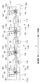
- a linear transport device 10 includes a base 11 extending in a rectangular shape in plan view, and a pair of linear drive units 20A and 20B provided on the base 11, And a slider 30 driven by each of the linear drive units 20A and 20B.
- the first circulation device 40 circulates the slider 30 from the downstream end of the one (forward movement side) linear drive unit 20A to the upstream end of the other (return side) linear drive unit 20B;
- a second circulation device 50 that circulates from the downstream end of the other linear drive unit 20B to the upstream end of one linear drive unit 20A is provided.
- the base 11 is a combination of a plurality of tables 11A.
- Each table 11A has a rectangular parallelepiped formed of a frame material.
- Each of the tables 11A includes a bottom plate, legs that can be adjusted in height attached to four corners of the bottom surface of the bottom plate, and a ceiling plate provided on the top of the legs as a framework.
- the longitudinal direction of the base 11 is assumed to be the X direction
- the horizontal direction orthogonal to the X direction is assumed to be the Y direction.
- one end side in the Y direction (left side in FIG. 3) is assumed to be the front. Also, in FIG.
- the right side of the figure is temporarily one end (the downstream end in the linear drive unit 20A, the upstream end in the linear drive unit 20B), and the left side is provisionally the other end (the upstream end in the linear drive unit 20A and the linear drive unit 20B). Downstream end).
- the linear drive units 20A and 20B extend in parallel with each other on the base 11 along the X direction.
- the front linear drive unit 20A front side in FIG. 1 forms a forward path (movement path) for driving the slider 30 from one end side in the X direction to the other end side.
- the rear linear drive unit 20B (the rear side in FIG. 1) forms a return path (movement path) for driving the slider 30 from the other end side in the X direction to the one end side.
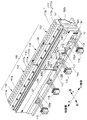
- the linear drive units 20A and 20B each constitute a linear motor, and each linear motor (linear drive units 20A and 20B) includes a plurality of stator units 100 and rails 103.
- the stator units 100 all have the same specifications, and are connected along the X direction.
- the rail 103 is fixed to the upper part of the plurality of stator units 100 along the X direction.
- Each stator unit 100 of the linear drive unit 20A will be described below.
- each stator unit 100 is an apparatus configured by connecting four sets of stators 110 having substantially the same specifications in series.
- the stator unit 100 includes a unit frame 101.
- the unit frame 101 is formed in a rectangular shape in plan view, and the longitudinal direction thereof is arranged along the X direction.
- the unit frame 101 is fixed to the upper surface of the base 11 with bolts (not shown).
- the unit frame 101 is an example of a member constituting the motor main body of each stator unit 100.
- covers 102 a (see FIG. 3) and 102 b are attached to both front and rear sides of each unit frame 101.
- stators 110 are assembled in pairs.
- the stators 110 are arranged in parallel with the rails 103 on the rear side of the rails 103.
- Each stator 110 is composed of a plurality of field electromagnets 111.
- the field electromagnet 111 includes a core 111a.
- the cores 111a are arranged in a line in the X direction.
- the core 111a has a comb shape in which the upper end is a magnetic pole and the lower end is connected to the adjacent core 111a.
- a field coil is wound around the core.
- 111b is an assembly of field coils.
- the field coil assembly 111 b is disposed in the longitudinal direction of the unit frame 101.
- the length Ls of the stator 110 in the X direction (direction along the movement path) is set to exactly 1 ⁇ 4 of the length Lf of the unit frame 101 in the X direction.
- the unit frame 101 has four stators 110 connected to the upper surface in the longitudinal direction.
- the stators 110 are connected in a straight line at the same pitch along the X direction.
- the interval between the cores 111a and 111a adjacent to each other at the end of the stator 110 is equal to the interval between the adjacent cores 111a and 111a in the middle portion of the stator 110.
- the X direction length Ls, the X direction length L of the unit frame 101, and the magnetic pole pitch are set.
- the stator unit 100 has a controller 200 (schematically illustrated in FIG. 3) provided for each stator 110.
- the controller 200 includes a microprocessor and other electronic components.
- the controller 200 obtains the position of the slider 30 with respect to the corresponding stator 110, and individually controls energization to each field coil of the corresponding stator 110 corresponding to the obtained position.
- Each controller 200 controls the supply current to the corresponding stator 110 based on the control or program of the main control device that controls the entire linear conveyance device.
- Each controller 200 is configured to be able to communicate with each other.
- four substrates 112 ⁇ / b> A, 112 ⁇ / b> B, 112 ⁇ / b> C, 112 ⁇ / b> D are attached to the unit frame 101 on the front side in the Y direction corresponding to the four stators 110 configured on the unit frame 101.
- a plate 113 is attached to each of the substrates 112A, 112B, 112C, and 112D.
- a connector 114 is provided on the plate 113.
- a wire harness 115 for connection with the outside is connected to the connector 114.
- the wire harness 115 is disposed so as to extend to the front side of the unit frame 101 in the Y direction (see FIG. 3).
- Each of the substrates 112A, 112B, 112C, and 112D has a length in the X direction set to be substantially the same as the length Ls of the stator 110.
- the substrates 112A, 112B, 112C, and 112D are arranged in the X direction at the same arrangement pitch as the stator 110. Accordingly, any of the substrates 112A, 112B, 112C, and 112D is contained in the front of the unit frame 101 (that is, is not protruding).
- the pitch is set to be equal to the arrangement pitch of the substrates 112A and 112B attached to the unit frame 101 (or the arrangement pitch of the substrates 112C and 112D).
- the connector 114 provided on the plate 113 includes a stator 110 corresponding to the substrate 112A (112B, 112C, 112D) of the plate 113 and a sensor provided on the substrate 112A (112B, 112C, 112D) of the plate 113.
- a wire harness 115 is connected to the connector 114. Therefore, the wire harness 115 electrically connects the corresponding stator 110 and sensors to the controller 200 corresponding to the stator 110.
- the controller 200 can control the energization of the field coil wound around the field core 111a of the corresponding stator 110.
- sub-connectors 116 are provided on both sides in the X direction of the respective boards 112A, 112B, 112C, and 112D.
- a harness 117 embodied by a flat cable or the like is connected to the sub connector 116.
- the harness 117 is composed of adjacent substrates (the substrate 112A and the substrate 112D of the unit frame 101 on the other end of the substrate 112A, the substrate 112A and the substrate 112B, the substrate 112B and the substrate 112C, the substrate 112C and the substrate 112D, and the substrate 112D.
- the board 112A of the unit frame 101 adjacent to the other end side of the board 112D, and so on) is electrically connected.
- each of the substrates 112A, 112B, 112C, and 112D is an example of a sensor substrate in the present invention.
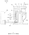
- the slider 30 is fixed to the slider 31 fitted to the rail 103, the top plate 32 attached to the upper portion of the slider 31, and the bottom surface of the top plate 32. And a plurality of permanent magnets 33 as movable elements facing the stator 110.
- grooves extending in the X direction are formed on both sides of the rail 103 as shown in FIG.
- the slider 31 has a recess having an inner wall that covers the upper portion of the rail 103 and is in sliding contact with the grooves on both sides. By introducing this recess into the end of the rail 103, the slider 31 is connected to the rail 103 so as to be slidable only in the longitudinal direction of the rail 103 in a state where it can be inserted and removed in the X direction.
- the top plate 32 is a structure that moves integrally with the slider 31.
- the top plate 32 functions as, for example, a pallet mounting component. On the pallet, a work as an object to be conveyed conveyed by the linear conveying device 10 is placed. Of course, according to a use, you may make it process the top plate 32 itself and to mount a workpiece
- the plurality of permanent magnets 33 as movers are arranged in a line at a predetermined arrangement pitch so that N poles and S poles appear alternately on the lower end face along the X direction.
- the magnetic pole of the field electromagnet 111 of the stator 110 changes depending on the power supply mode supplied to the field coil.
- the controller 200 supplies the field coil with a current in any one of the u phase, the v phase, and the w phase having different phases.
- the magnetic flux generated in the field electromagnet 111 and the magnetic flux generated by the permanent magnet 33 are caused to interact with each other in accordance with the change in the magnetic pole of the field electromagnet 111, and the field electromagnet 111 and the slider 30 of the stator 110.
- the controller 200 can reciprocate the slider 30 at a predetermined speed along the X direction by controlling the energization of the field electromagnet 111 to the field coil. .
- the front end wall 34 is fixed to the bottom surface on the front end side of the top plate of the slider 30.
- Two linear scales (magnetic scales) S1 and S2 included in the position detection device S are attached to the back surface of the front end wall 34 (the surface facing the substrates 112A, 112B, 112C, and 112D).
- the position detection device S is a unit including the “position detection means” of the present invention.
- the substrates 112A, 112B, 112C, and 112D are viewed from the left side of FIG. 3, that is, the front side in the Y direction, and the magnetic scales S1 and S2 are the left side of FIG.
- the magnetic scales S1 and S2 extend parallel to each other along the X direction in the vertical direction.
- the magnetic scale S1 provided on the upper side is composed of a plurality of permanent magnets S11 and S12.
- the permanent magnets S11 and S12 are attached to the back surface of the front end wall 34 at equal pitches along the X direction with alternating magnetic poles.
- One permanent magnet S11 has an N-pole magnetic pole on the end surface on the substrate 112A (112B, 112C, 112D) side in the Y direction.
- the magnetic pole on the end surface on the substrate 112A (112B, 112C, 112D) side in the Y direction is the S pole.
- the one permanent magnet S11 and the other permanent magnet S12 are arranged at an equal arrangement pitch within a preset scale length L.
- the scale length L is longer than the length of the substrate 112A (112B, 112C, 112D) (the length Ls substantially the same as the length Ls of the stator 110).
- both end portions of the magnetic scale S1 are composed of permanent magnets S11 having the same magnetic poles.
- both end portions of the magnetic scale S1 are composed of permanent magnets S11 having N poles (the magnetic poles on the side surfaces of the substrates 112A (112B, 112C, 112D) in the Y direction are N poles). Both ends of S1 may be composed of S-pole permanent magnets S12.
- the lower magnetic scale S2 is composed of a pair of permanent magnets S21 and S22 that are stuck side by side.
- the permanent magnets S21 and S22 constituting each set have different magnetic poles on the end surface on the substrate 112A (112B) side.
- One set of permanent magnets S21 and S22 is arranged directly below the other end of the upper magnetic scale S1. Further, the other set of permanent magnets S21 and S22 is spaced from one set at one end side.
- the distance Lz between one set of permanent magnets S21 and S22 and the other set of permanent magnets S21 and S22 is set longer than the length Ls of the stator 110 in the X direction by a predetermined dimension.
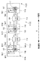
- each substrate 112A, 112B, 112C, 112D has a pair of first sensors SA1, SA2 that output a sine wave waveform signal (A phase) and a cosine wave waveform signal (B phase). ) Is output, a pair of second sensors SB1 and SB2 are provided. Regarding the relationship between the sine wave and the cosine wave, the A phase may be a cosine wave and the B phase may be a sine wave. Further, in order to detect the magnetic scale S2, each substrate 112A, 112B, 112C, 112D is provided with a third sensor SZ that outputs a Z-phase signal (Z-phase).
- Each of the sensors SA1 to SZ is composed of, for example, a Hall sensor, measures the magnetic flux density of the corresponding permanent magnets S11, S12, S21, and S22, and outputs a waveform signal of an output voltage (amplitude) corresponding to the magnetic flux density. Is configured to do.
- the first sensors SA1 and SA2 are disposed on the same line along the X direction on the substrate 112A (112B, 112C, and 112D) so as to be separated from one end side and the other end side.
- the heights of the first sensors SA1 and SA2 are set at positions that face the magnetic scale S1 in the Y direction when the first sensors SA1 and SA2 are assembled. Further, at the time of assembly, the first sensors SA1 and SA2 face the permanent magnets S11 and S12 with a slight gap in the Y direction (front and rear) with respect to the magnetic scale S1.
- the second sensors SB1 and SB2 are disposed on the substrate 112A (112B, 112C, and 112D) so as to be separated from one end and the other end on a line along the X direction.
- the heights of both the second sensors SB1, SB2 are set at positions where the second sensors SB1, SB2 face the magnetic scale S1 in the Y direction when assembled. Further, at the time of assembly, the second sensors SB1 and SB2 face the permanent magnets S11 and S12 with a slight gap in the Y direction (front and rear) with respect to the magnetic scale S1.
- the interval in the X direction between one first sensor SA1 and the other first sensor SA2 is set in association with the adjacent substrates 112A, 112B, 112C, 112D. That is, the distance from the first sensor SA2 disposed on the other end side of the substrate 112A on one end side of a certain substrate 112B to the first sensor SA1 disposed on one end side of the substrate 112C on the other end side of the substrate 112B. Is set equal to the scale length L. Therefore, both the first sensors SA2 and SA1 are opposed to both end portions of the magnetic scale S1 at the same time across the substrate 112B.
- the second sensor SB2 disposed on the other end side of the substrate 112A on one end side of the substrate 112B and the second sensor SB1 disposed on the one end side of the substrate 112C on the other end side of the substrate 112B.
- the distance is set equal to the scale length L. Therefore, both the second sensors SB2 and SB1 are opposed to both ends of the magnetic scale S1 with the substrate 112B interposed therebetween.
- first sensors SA1 and SA2 and the second sensors SB1 and SB2 are set at an interval facing the permanent magnet S12 (S11) having different magnetic poles at the same timing.
- the arrangement pitch of each of the first sensor SA1 and the second sensor SB1, and the first sensor SA2 and the second sensor SB2 is 1 ⁇ 2 the arrangement pitch of the two adjacent permanent magnets S11 (S12) and permanent magnet S12 (S11). , Or 3/2, and further multiplied by an integer multiple of 2 respectively.
- n is an integer of 0 or more
- the length is set by multiplying ⁇ n + (1/2) ⁇ by the arrangement pitch.
- the A-phase waveform signal and the B-phase waveform signal have a relationship in which one (for example, A phase) is a sine wave and the other (for example, B phase) is a cosine wave. Therefore, the phases of the waveform signals output from the first sensors SA1 and SA2 and the second sensors SB1 and SB2 are shifted from each other by ⁇ / 2.
- Both waveform signals are output with the same amplitude and the same period, in principle, except that the phases are different.
- the width in the X direction of the permanent magnet S11 at both ends of the magnetic scale S1 is set to 1 ⁇ 2 of the width of the remaining permanent magnets S11 and S12. Therefore, the magnetic flux density is reduced at both ends of the magnetic scale S1. Therefore, at the timing when the first sensors SA1 and SA2 face the permanent magnets S11 at both ends of the magnetic scale S1, the amplitudes of the waveform signals output from the first sensors SA1 and SA2 are the scales of the first sensors SA1 and SA2, respectively.
- the amplitude of the waveform signal output by each of the first sensors SA1 and SA2 at the timing of facing the permanent magnet S11 having the same polarity excluding both ends of S1 is half.
- the amplitudes of the waveform signals output at the timing when the second sensors SB1 and SB2 face the permanent magnets S11 having the same polarity at both ends of the magnetic scale S1 are the same. Therefore, even if the first sensors SA1 and SA2 face each other at the same time at both ends of the magnetic scale S1, it is possible to prevent the synthesized waveform signal from having a larger amplitude than the waveform signal when other parts are detected. Can do.
- the arrangement pitch which is the distance between the edge of the permanent magnet S11 at the end and the center of the adjacent permanent magnet S12 in the X direction, is the same as the arrangement pitch of the other two adjacent permanent magnets S11 and S12.
- one third sensor SZ is provided for each substrate 112A (112B, 112C, 112D). Specifically, the third sensor SZ is attached at a position close to one end side of the stator 110. Therefore, in the illustrated example, the first sensor SA1 on the one end side is in the same position in the X direction and is aligned at the top and bottom of the drawing. Further, an interval Lz between the adjacent third sensors SZ, for example, an interval Lz between the third sensor SZ of the substrate 112B and the third sensor SZ of any one of the substrates 112C (112D) adjacent to the substrate 112B is: This is the same as the length Ls of the stator 110 in the X direction.
- the length in the X direction from the other end of the substrate 112B to the third sensor SZ of the substrate 112C adjacent to the other end is defined as an offset amount L1, and the third sensor of the substrate 112B from one end of the substrate 112B.
- the offset amount L2 When the length in the X direction up to SZ is the offset amount L2, both offset amounts L1 and L2 are as short as possible.
- the substrates 112B, 112C, and 112D with respect to the distance Lz between the third sensors SZ and the offset amounts L1 and L2 on both ends.
- the interval between the first sensors SA1 of adjacent substrates is Lz. .
- each of the substrates 112A, 112B, 112C, 112D includes an adding circuit S8.
- the adder circuit S8 is adjacent to the waveform signal output via the harness 117 by the first sensor SA2 provided on the other end of the substrate 112A adjacent to one end of the substrate 112B and the other end of the substrate 112B.
- the first sensor SA1 provided on one end side of the substrate 112C adds the waveform signal output via the harness 117 and outputs it to the connector 114.
- the waveform signal output via the harness 117 by the second sensor SB2 provided on the other end side of the substrate 112A adjacent to one end side of a certain substrate 112B and the substrate 112C adjacent to the other end side of the substrate 112B.
- the second sensor SB ⁇ b> 1 provided on one end side adds the waveform signal output via the harness 117 and outputs it to the connector 114.
- the controller 200 is supplied with the A phase waveform signal, the B phase waveform signal detected on both sides of a certain board 112B, and the third sensor SZ of this board 112B. And the Z-phase signal detected by the third sensor SZ of the substrate 112C on the other end side of the substrate 112B are input.
- the addition circuit S8 of the substrate 112B includes an A-phase waveform signal from the first sensor SA2 on the other end side of the substrate 112A adjacent to one end side, and a B-phase waveform signal from the second sensor SB2 on the other end side. , Respectively.
- the adder circuit S8 adds these waveform signals for every A phase and every B phase, and outputs a sum signal. This sum signal is input to the controller 200 of the board 112B via the wire harness 115.
- the third sensor SZ of the substrate 112B detects a pair of permanent magnets S21 and S22 on the other end side of the magnetic scale S2 and outputs a Z-phase signal. This output is input to the controller 200 of the substrate 112B. Further, the controller 200 of the substrate 112B changes the amplitude of the A-phase and B-phase waveform signals from the substrate 112A adjacent to the one end side with the timing at which the magnetic scale S2 on the other end side passes the third sensor SZ as a base point. Count. Based on such a signal, the controller 200 of the substrate 112B can obtain the position of the slider 30 with reference to the origin position.
- the addition circuit S8 of the substrate 112B includes the A-phase waveform signal having a half amplitude output from the first sensor SA2 on the other end side of the substrate 112A and the first sensor SA1 on the one end side of the substrate 112C.
- the A-phase waveform signal having a 1/2 amplitude output from is input.
- the addition circuit S8 has a 1/2 amplitude A-phase waveform signal output from the first sensor SA2 on the other end side of the substrate 112A and a 1 / output signal output from the first sensor SA1 on the one end side of the substrate 112C.
- the two amplitude A phase waveform signals are added together.
- the adder circuit S8 outputs an A-phase waveform signal having 2/2 amplitude. Therefore, the controller 200 of the substrate 112B receives the A-phase waveform signal with 2/2 amplitude output from the adder circuit S8.
- the permanent magnets S21 and S22 at the other end of the magnetic scale S2 are also It reaches the third sensor SZ of the substrate 112C.
- the controller 200 of the substrate 112C can detect the position of the slider 30 with respect to the corresponding stator 110 based on the detection of the third sensor SZ. .
- the controller 200 of the substrate 112C detects the position of the slider 30 with respect to the stator 110 based on the input A-phase, B-phase, and Z-phase signals, and based on a program predetermined by the main controller.
- the controller 200 of the substrate 112C detects the position of the slider 30 with respect to the stator 110 based on the input A-phase, B-phase, and Z-phase signals, and based on a program predetermined by the main controller.
- it is possible to control the movement of the slider 30 by controlling the energization of the field electromagnet 111 to the field coil corresponding to the position of the slider 30.
- the permanent magnet S11 at one end side of the magnetic scale S1 moves away from the first sensor SA2 at the other end side of the substrate 112A and reaches the second sensor SB2 at the other end side. .
- the permanent magnet S11 at the other end of the magnetic scale S1 reaches the second sensor SB1 at one end of the substrate 112C.
- the addition circuit S8 of the substrate 112B has a 1/2 amplitude B-phase waveform signal output from the second sensor SB2 of the substrate 112A and a 1/2 output from the first sensor SB1 of the substrate 112C. An amplitude B phase waveform signal is input.
- the addition circuit S8 has a 1/2 amplitude B phase waveform signal from the second sensor SB2 on the other end side of the substrate 112A and a 1/2 amplitude B signal from the second sensor SB1 on the one end side of the substrate 112C. Add together the phase waveform signal.
- the adding circuit S8 outputs a B-phase waveform signal having 2/2 amplitude. Therefore, the controller 200 of the substrate 112B is supplied with the 2/2 amplitude B phase waveform signal output from the adder circuit S8. Therefore, the continuity of the B phase waveform signal is maintained.
- the B-phase waveform signal input to the controller 200 of the substrate 112B is processed as a series of smooth B-phase waveform signals.
- the permanent magnet S11 at one end side of the magnetic scale S1 moves away from the second sensor SB2 on the other end side of the substrate 112A adjacent to the one end side. Accordingly, the outputs from the first sensor SA2 and the second sensor SB2 on the other end side of the substrate 112A are zero.
- the permanent magnets S11 and S12 on the other end side of the magnetic scale S1 continue to face the first sensor SA1 and the second sensor SB1 on one end side of the substrate 112C adjacent to the other end side. Accordingly, the first sensor SA1 and the second sensor SB1 respectively output a 2/2 amplitude A phase waveform signal and a 2/2 amplitude B phase waveform signal.
- A-phase and B-phase waveform signals are added to the outputs from the first sensor SA2 and the second sensor SB2 on the other end side of the substrate 112A by the addition circuit S8 of the substrate 112B, and input to the controller 200 of the substrate 112B. Is done.
- the input waveform signal is added to the A phase waveform signal and the B phase waveform signal input to the controller 200 before that, respectively, for each A phase and B phase.
- the added A-phase and B-phase waveform signals are both 2/2 amplitude waveform signals. Therefore, the A-phase and B-phase waveform signals are ensured in continuity with the already input signals.
- the controller 200 of the substrate 112B can detect the position of the slider 30 with respect to the stator 110 to which the substrate 112B is attached by counting each added waveform signal.
- the controller 200 of a certain board uses the outputs of the sensors of the boards arranged on both sides of the board 112B to move the slider in a stroke range longer in the X direction than the stator 110. 30 position detections can be realized. Further, when a certain board is located at the end of the unit frame 101, it is possible to use the output of the sensors on the board of the unit frame 101 adjacent to the unit frame 101.
- each of the first and second sensors SA1 and SB1 on one end side is an example of the upstream position detection means of the present invention.
- each of the first and second sensors SA2 and SB2 on the other end side is an example of the downstream position detecting means of the present invention.
- the addition circuit S8 is an example of a position detection signal summing unit.
- the position detection device S according to the present embodiment includes the first and second sensors SA1 and SB1 on one end side, the first and second sensors SA2 and SB2, the third sensor SZ on the other end side, and the magnetic scale S1. , S2 is included.
- the unit frame 101 corresponds to the four stators 110 constituting the unit frame 101, and 4
- Two substrates 112A, 112B, 112C, and 112D are attached to the front side in the Y direction in order from one end side to the other end side.
- a plate 113 is attached to each of the substrates 112A, 112B, 112C, and 112D.
- Connectors 114 are provided on the plates 113, respectively.
- Each connector 114 is connected to a wire harness 115 for connection to the outside.
- the wire harness 115 is disposed so as to extend to the front side of the unit frame 101 in the Y direction.
- the slider 30 moves from the other end side to one end side.
- the detection process on the return path side will be described with reference to the substrate 112B.
- the first sensor SA1 on one end of the substrate 112C For example, at the timing when the permanent magnet S11 at one end of the magnetic scale S1 passes through the first sensor SA1 on one end of the substrate 112C on the upstream side of a certain substrate 112B, the first sensor SA1 on one end of the substrate 112C.
- the second sensor SB1 outputs A-phase and B-phase waveform signals.
- the third sensor SZ outputs a Z-phase signal.
- the A-phase and B-phase waveform signals are input to the addition circuit S8 of the substrate 112B via the harness 117.
- the Z-phase signal is input to the controller 200 of the board 112 ⁇ / b> C, and is also input to the controller 200 of the board 112 ⁇ / b> B via the harness 117 and the wire harness 115.
- the adder circuit S8 outputs A-phase and B-phase waveform signals via the wire harness 115.
- the output A-phase and B-phase waveform signals are input to the controller 200 of the substrate 112B together with the Z-phase signal output from the third sensor SZ of the substrate 112C. Thereafter, the signals of the A phase, the B phase, and the Z phase are the same as in the forward linear drive unit 20A, the slider 30 reaches the substrate 112A, and the magnetic scale S1 is the first one on the one end side of the substrate 112B.
- the signal is input to the controller 200 of the substrate 112B until it passes the sensor SA1 (thus, the third sensor SZ of the substrate 112B).
- the controller 200 of the substrate 112B is based on the timing at which the pair of permanent magnets S21 and S22 on one end side of the magnetic scale S2 arrives at the third sensor SZ on the substrate 112C, from the first sensor SA1 on one end side of the substrate 112C. A change in amplitude between the A-phase waveform signal and the B-phase waveform signal from the second sensor SB1 is counted. Based on such signal processing, the controller 200 of the substrate 112 ⁇ / b> B can detect the position of the slider 30. At this timing, none of the permanent magnets S11 and S12 of the magnetic scale S1 has reached the first sensor SA2 and the second sensor SB2 on the other end side of the substrate 112A on one end side. Therefore, the waveform signals of the sensors SA1 and SB1 on one end side of the substrate 112C are exclusively input to the substrate 112B with an amplitude of 2/2.
- the addition circuit S8 of the substrate 112B has a half-phase B phase waveform signal from the second sensor SB2 on the other end side of the substrate 112A and the second sensor SB1 on the one end side of the substrate 112C.
- a half-phase B phase waveform signal is input via the corresponding harness 117.
- the adder circuit S8 adds these B-phase waveform signals and outputs a 2/2 amplitude addition signal.
- the output addition signal is input to the controller 200 of the substrate 112B.
- the 2/2 amplitude addition signal input to the controller 200 is added to the B phase waveform signal output from the second sensor SB1 on one end side of the substrate 112C adjacent to the other end side before that.
- the added sum signal is smoothly continuous with respect to the previous waveform signal.
- the permanent magnet S11 at one end of the magnetic scale S1 reaches the first sensor SA2 at the other end of the substrate 112A
- the permanent magnet S11 at the other end of the magnetic scale S1 is replaced with the substrate 112C.
- the addition circuit S8 of the substrate 112B has a 1/2 amplitude A-phase waveform signal from the first sensor SA2 on the other end side of the substrate 112A and the first sensor SA1 on the one end side of the substrate 112C.
- a half-phase A-phase waveform signal is input via the corresponding harness 117.
- the adder circuit S8 adds these A-phase waveform signals and outputs a 2/2 amplitude addition signal.
- the output addition signal is input to the controller 200 of the substrate 112B.
- the addition signal of 2/2 amplitude input to the controller 200 is added to the A-phase waveform signal output from the first sensor SA1 on one end side of the substrate 112C adjacent to the other end side before that.
- the added sum signal is smoothly continuous with respect to the previous waveform signal. Furthermore, at the timing when the permanent magnet S11 at one end of the magnetic scale S1 reaches the first sensor SA2 at the other end of the substrate 112A, the pair of permanent magnets S21 and S22 on one end of the magnetic scale S2 It is detected by the third sensor SZ of 112B.
- the pair of permanent magnets S21 and S22 on the other end side of the magnetic scale S2 is detected by the third sensor SZ on the substrate 112C. Therefore, even in the process in which the pair of permanent magnets S21 and S22 on one end side of the magnetic scale S2 passes through the substrate 112C and is detected by the third sensor SZ on the substrate 112B, the origin position signal corresponds to the length Lz. Thus, the controller 200 of the substrate 112B can accurately calculate the position of the slider 30 without losing the origin position information.
- the controller 200 of the board 112B detects the position of the slider 30 with respect to the stator 110 based on the input A-phase, B-phase, and Z-phase signals, and based on a program predetermined by the main controller.
- the energization to the field coil of the field electromagnet 111 is controlled, and the movement of the slider 30 is controlled.
- the first circulation device 40 of the linear conveyance device 10 includes a conveyance unit 41, a drive unit 42, a slider transfer unit 43, and a slider transfer unit 44.
- the transport unit 41 is a unit that can reciprocate in the Y direction on the other end side of the linear drive unit 20A on the forward path side and the linear drive unit 20B on the return path side.
- the receiving position of the slider 30 is set at the downstream end on the other end side of the linear drive unit 20A on the forward path side.
- a delivery position at which the slider 30 is delivered to the other end side of the return path side linear drive unit 20B is set at the upstream end of the other side of the return path side linear drive unit 20B.
- the slider 30 is received by the transport unit 41 from the other end side of the linear drive unit 20A on the forward path side.
- the slider 30 is delivered from the transport unit 41 to the other end side of the linear drive unit 20B on the return path in the posture as it is.
- the drive unit 42 is a unit that drives the transport unit 41 between a receiving position and a delivery position.
- the slider transfer unit 43 can be engaged and disengaged from the slider 30.
- the slider transfer unit 43 is engaged with the slider 30 in the linear drive unit 20A on the forward path side, and transfers the engaged slider 30 to the receiving position.
- the slider transfer unit 43 transfers the slider 30 from the downstream end of the linear drive unit 20A to the receiving position.
- the drive unit 42 transports the transport unit 41 from the receiving position to the delivery position.
- the slider transfer unit 44 can be engaged and disengaged from the slider 30.
- the slider transfer unit 44 engages with the slider 30 on the transport unit 41 that has arrived at the delivery position, and transfers the engaged slider 30 to the upstream end of the linear drive unit 20B.
- the slider transfer unit 44 transfers the slider 30 from the transport unit 41 to the other end side of the linear drive unit 20B on the return path, so that the slider 30 is kept in its posture. Then, it is delivered to the other end side of the linear drive unit 20B on the return path side.
- the slider 30 conveyed from the forward-side linear drive unit 20A can be circulated to the return-side linear drive unit 20B while maintaining the same posture.
- the second circulation device 50 includes a transport unit 51, a drive unit 52, a slider transfer unit 53, and a slider transfer unit 54.
- the transport unit 51 is a unit that can reciprocate in the Y direction on one end side of the linear drive unit 20B on the return path side and the linear drive unit 20A on the forward path side.
- the receiving position of the slider 30 is set at the downstream end on one end side of the linear drive unit 20B on the return path side.
- a delivery position at which the slider 30 is delivered to one end side of the forward path side linear drive unit 20A is set at the upstream end of one end side of the forward path side linear drive unit 20A.
- the slider 30 is received by the transport unit 51 from one end side of the linear drive unit 20B on the return path side.
- the slider 30 is delivered from the transport unit 51 to the one end side of the linear drive unit 20A on the forward path as it is.
- the drive unit 52 is a unit that drives the transport unit 51 between a receiving position and a delivery position.
- the slider transfer unit 53 can be engaged with and disengaged from the slider 30.
- the slider transfer unit 53 engages with the slider 30 in the linear drive unit 20B on the return path side, and transfers the engaged slider 30 to the receiving position.
- the slider transfer unit 53 transfers the slider 30 from the downstream end of the linear drive unit 20B to the receiving position.
- the drive unit 52 transports the transport unit 51 from the receiving position to the delivery position.
- the slider transfer unit 54 can be engaged and disengaged from the slider 30.
- the slider transfer unit 54 engages with the slider 30 on the transport unit 51 that has arrived at the delivery position, and transfers the engaged slider 30 to the upstream end of the linear drive unit 20A.
- the slider transport unit 54 transports the slider 30 from the transport unit 51 to one end side of the linear drive unit 20A on the forward path side. It is delivered to one end side of the linear drive unit 20A on the forward path side.
- the slider 30 conveyed from the linear drive unit 20B on the return path can be circulated to the linear drive unit 20A on the forward path while maintaining the same posture.
- the operator can arbitrarily introduce the slider 30 into the linear drive unit 20A on the forward path side.
- the number of sliders 30 introduced simultaneously to each of the linear drive units 20A and 20B can be arbitrarily set within a range where overflow does not occur.
- the linear transport device 10 includes a plurality of linear motors (the linear drive unit 20A on the forward path side and the linear drive unit 20B on the return path side) and the linear motor from the other end to the one end of the adjacent linear motor.
- a circulation device for circulating the slider is provided, a circulation path for the slider including a plurality of linear motors and a plurality of circulation devices is configured, and one or a plurality of the sliders are moved in the circulation path. .
- one end side sensor substrate 60A as an auxiliary sensor substrate is installed in the second circulation device 50 for each of the linear drive units 20A and 20B.
- the other end side sensor substrate 61A as an auxiliary sensor substrate is installed in the first circulation device 40 for each of the linear drive units 20A and 20B.
- the one end side sensor substrate 60A is provided with an upstream side of the substrate 112A of the stator 110 that constitutes an upstream end of the forward side linear drive unit 20A and a downstream end of the return side linear drive unit 20B.
- Each of the stators 110 is disposed adjacent to the downstream side of the substrate 112A.
- the other end side sensor board 61A is connected to the downstream side of the board 112D of the stator 110 that constitutes the downstream end of the forward side linear drive part 20A and the return side linear drive part 20B.
- the upstream side of the substrate 112D of the stator 110 constituting the upstream end of the stator 110, respectively.
- a first sensor SA2 and a second sensor SB2 are provided on each one-end side sensor substrate 60A of the forward path side linear drive unit 20A and the return path side linear drive unit 20B.
- a sub connector 116 is provided on the other end side of the one end side sensor substrate 60A.
- a harness 117 is connected to the sub connector 116.
- Each one end side sensor substrate 60A and the substrate 112A adjacent to the one end side sensor substrate 60A are connected by a harness 117, respectively.
- substrate 60A is provided in the A phase waveform signal from 1st sensor SA1 provided in the board
- the sum signal with the A phase waveform signal from the first sensor SA2 is received.
- the controller 200 connected to the substrate 112A includes a B-phase waveform signal from the second sensor SB1 provided on the substrate 112B and a B-phase waveform signal from the second sensor SB2 provided on the one-end side sensor substrate 60A. Receive the sum signal.
- the controller 200 connected to the substrate 112A receives a Z-phase signal from the third sensor SZ of the substrate 112A. Based on these signals, the controller 200 connected to the substrate 112A detects the position of the slider 30 with respect to the stator 110 to which the substrate 112A is attached.
- a first sensor SA1, a second sensor SB1, and a third sensor SZ are provided on each of the other end side sensor boards 61A of the forward path side linear drive unit 20A and the return path side linear drive unit 20B. It is done.
- a sub connector 116 is provided on one end side of the other end side sensor substrate 61A.
- a harness 117 is connected to the sub connector 116.
- Each other end side sensor board 61A and the board 112D adjacent to the other end side sensor board 61A are connected by a harness 117, respectively.
- the controller 200 connected to the substrate 112D adjacent to the upstream side of each other-end side sensor substrate 61A receives the A-phase waveform signal from the first sensor SA2 provided on the substrate 112C and the other-end sensor substrate 61A.
- the sum signal with the A phase waveform signal from the provided first sensor SA1 is received.
- the controller 200 connected to the substrate 112D includes a B phase waveform signal from the second sensor SB2 provided on the substrate 112C and a B phase waveform signal from the second sensor SB1 provided on the other end side sensor substrate 61A. The sum signal is received.
- the controller 200 connected to the substrate 112D adjacent to the upstream side of the other end side sensor substrate 61A is connected to the Z sensor from the third sensor SZ on the substrate 112D. Detect the phase signal.
- the controller 200 connected to the substrate 112D adjacent to the downstream side of the other end side sensor substrate 61A receives a Z-phase signal from the third sensor SZ provided on the other end side sensor substrate 61A. In the middle of the movement, a Z-phase signal from the third sensor SZ of the substrate 112D adjacent to the downstream side of the other end side sensor substrate 61A is detected. Based on these Z-phase signals, each controller 200 detects the position of the slider 30 with respect to the stator 110 to which the corresponding substrate 112D is attached.
- the forward-side linear drive unit 20A and the return-side linear drive unit 20B that drive the slider 30 in the X direction (the direction along the movement path) are , Each of which includes a plurality of stator units 100.
- Each stator unit 100 includes a plurality of stators 110, respectively.
- Each stator 110 includes sensor substrates 112A to 112B.
- Each of the sensor substrates 112A to 112B includes an adding circuit S8.
- the adder circuit S8 adds the position detection signals from the position detection means provided on the substrates 112A and 112C on both sides of a certain substrate 112B, and outputs a sum signal.
- the controller 200 connected to a certain board 112B obtains the position of the slider 30 relative to the stator 110 based on the sum signal output from the adder circuit S8. Therefore, the controller 200 detects the position of the slider 30 with respect to the stator 110 within the moving stroke range of the slider 30 longer than the length of the substrate 112B provided on the stator 110, that is, the length Ls of the stator 110. be able to.
- the substrates 112A to 112D as the sensor substrates are accommodated inside the unit frame 101 that constitutes the motor main body of the corresponding stator unit 100, there is no possibility that an extra protruding portion is formed. Therefore, when the stator unit 100 is a single unit, handling becomes much easier.
- a plurality of stator units 100 are newly connected to the base 11 or the like, when the connected stator units 100 are removed, or the stator units 100 are added to the existing linear drive units 20A and 20B. In such a case, it is not necessary to disassemble the stator unit 100 itself, that is, to attach / detach the substrate 112A or 112D to / from the unit frame 101. Therefore, it is possible to obtain a linear conveyance device that is efficient in connection work and removal work.
- the first sensor SA1, SA2 and the second sensor SB1, SB2 are provided for each of the sensor boards 112A, 112B, 112C, 112D as the position detection means.
- the first sensors SA1 and SA2 include two hall sensors (sensor SA1) arranged on one end side of the stator 110 and two hall sensors (sensor SA2) arranged on the other end side in the X direction.
- a sensor set is formed as a set.
- the second sensors SB1 and SB2 also have a hall sensor (sensor SB1) arranged on one end side of the stator 110 and a hall sensor (sensor SB2) arranged on the other end side. ) Is composed of two sensor sets.
- the adding circuit S8 includes a position detection signal from a hall sensor disposed on the other end side of the stator 110 adjacent to one end of each stator 110 and a stator 110 adjacent to the other end side for each sensor set.
- a position detection signal summing unit that outputs a continuous waveform signal for each sensor set by adding the position detection signals from Halles arranged on one end side of the sensor.
- each of the substrates 112A to 112D is set to the same size as the corresponding stator 110. Therefore, it is possible to detect the position of the mover over a relatively wide stroke range although each of the substrates 112A to 112D is fixed to the unit frame 101 without being displaced in the X direction. .
- each arrangement pitch of 1st sensor SA1 and 2nd sensor SB1, 1st sensor SA2, and 2nd sensor S is between the adjacent permanent magnet S11 and permanent magnet S12 in magnetic scale S1.
- the arrangement pitch is 1/2, 3/2. That is, the arrangement pitch in the X direction between the one end sides and the other end sides of the sensors constituting the two sensor sets is equal to the arrangement pitch of the plurality of permanent magnets S11 and permanent magnets S12 constituting the magnetic scale S1 ⁇ n + (1 / 2) ⁇ (where n is an integer greater than or equal to 0).
- the phase of the waveform signal output from the sensor set formed by each of the first sensors SA1 and SA2 and the waveform signal output from the sensor set configured by the second sensors SB1 and SB2 are relatively shifted by ⁇ / 2. It becomes. For this reason, in this embodiment, by using two sensor sets, one can be used as a sine wave and the other as a cosine wave, so that the resolution can be improved and a high position detection function can be exhibited.
- the mounting position of the third sensor SZ as the origin position sensor is aligned with a position close to one end side of the stator 110 in the X direction. Therefore, the offset amounts L1 and L2 with respect to the length Ls of the stator 110 in the X direction are as short as possible. Therefore, when the magnetic scale S 1 of the slider 30 starts to move from a certain stator 110 in the stator unit 100 to the stator 110 adjacent to the stator 110, the magnetic scale S 1 of the plurality of stator units 100 is further increased. When starting to move from one stator unit 100 to another stator unit 100 adjacent to the stator unit 100, the origin position information can be obtained immediately. As a result, the position detection of the slider 30 can be realized in a relatively long stroke range.
- the linear drive unit 20A on the forward path side is adjacent to the one end side sensor substrate 60A attached adjacent to one end side (upstream side in the moving direction of the slider 30) and the other end side end portion.
- the other end side sensor board 61A is provided.
- the linear drive unit 20B on the return path side is attached to one end side sensor substrate 60A adjacent to one end side (downstream side in the moving direction of the slider 30) and the other end attached adjacent to the other end side end.
- Side sensor substrate 61B Each one-end sensor substrate 60A is provided with a first sensor SA2 and a second sensor SB2 corresponding to the sensors on the other end side of the substrates 112A, 112B, 112C, and 112D.
- Each other end side sensor substrate 61A is provided with a first sensor SA1, a second sensor SB1, and a third sensor SZ corresponding to the one end side sensors of the substrates 112A, 112B, 112C, and 112D.
- the controller 200 of the stator 110 constituting the upstream end portion is output from the one end side sensor substrate 60A as an auxiliary sensor substrate.
- a signal can also be received. Therefore, the controller 200 outputs a signal output from the third sensor SZ of the board 112A provided on the stator 110, an output signal from the board 112B adjacent to the downstream side of the board 112A, and the one end side sensor board 60A.
- the position of each slider 30 entering the stator 110 constituting the upstream end portion of the linear drive unit 20A is detected based on the output signal from the control signal, and the movement can be controlled.
- the controller 200 Immediately, the position of the slider 30 can be detected and the movement of the slider 30 can be controlled.
- the controller 200 of the stator 110 constituting the downstream end portion can also receive a signal output from the sensor substrate 61A as an auxiliary sensor substrate. Therefore, the controller 200 outputs a signal output from the third sensor SZ of the substrate 112D of the stator 110, a signal output from the substrate 112C upstream of the substrate 112D, and a signal output from the sensor substrate 61A. Based on the above, it is possible to detect the position of the slider 30 that is about to exit from the stator 110 that constitutes the downstream end of the linear drive unit 20A, and to control the movement.
- the controller 200 of the stator 110 constituting the upstream end portion also receives a signal output from the other end side sensor substrate 61A as an auxiliary sensor substrate. be able to. Therefore, the controller 200 includes a signal output from the third sensor SZ of the substrate 112D provided in the stator 110, a signal output from the substrate 112C adjacent to the downstream side of the substrate 112D, and the other end side sensor. Based on the signal output from the substrate 61A, it is possible to detect the position of the slider 30 delivered to the stator 110 constituting the upstream end of the linear drive unit 20B and control the delivery operation. Therefore, when the slider 30 is delivered from the first circulation device 40 to the upstream end portion and the slider 30 enters the most upstream stator 110, the position of the slider 30 is immediately detected, and the slider 30 moves. Can be controlled.
- the controller 200 of the stator 110 constituting the downstream end can receive a signal from the sensor substrate 60A as an auxiliary sensor substrate. Therefore, the controller 200 outputs a signal output from the third sensor SZ of the board 112A of the stator 110, an output signal from the board 112B adjacent to the upstream side of the board 112A, and the one end side sensor board 60A. Based on the output signal, the position of the slider 30 received by the second circulation device 50 from the stator 110 constituting the downstream end of the linear drive unit 20B can be detected and the movement can be controlled.
- the boards 117 (112A and 112B, 112B and 112C, 112C and 112D, 112D and 112A, or 60A and 112A, 112D and 61A) connected to both sides are electrically connected to the harness 117, respectively. Connected with.
- the harness 117 can be made as short as possible. Therefore, in the harness 117, there is no fear of noise superimposition, and the differential transmission method can be switched to the single end transmission method.
- the senor is preferably a hall sensor, but a sensor element other than the hall sensor may be used.
- the expression “straight” or “straight” is an engineering meaning and is not intended to exclude a curved path.
- the forward drive side linear drive unit 20A is rotated 180 degrees when viewed from above and replaced with the return drive side linear drive unit 20B of the above-described embodiment, and the forward drive side and the return pass side are configured by the same linear drive unit 20A. Also good.
- the boards 112A to 112D, the connectors 114 and 116, and the wire harnesses 115 and 117 are on the Y direction front side on the forward path side and on the Y path rear side on the return path side, thereby improving the serviceability.
- the position detection signal summation unit of the sensor board includes the position detection signal from the downstream position detection unit of the sensor board adjacent to the upstream side of the sensor board in the movement direction, and the movement direction.
- the position detection signal from the upstream position detection means of the sensor board adjacent to the downstream side of the sensor board is added together, and the resultant signal is output. Therefore, despite the fact that the sensor board is housed inside the corresponding stator, the control device, like the configuration of Patent Document 2, has a slider moving stroke range that is longer than the length of the stator. The position can be detected.
- each sensor board is mounted so as to be within the dimensions of the corresponding stator, there is no possibility of an extra protruding portion.
- the linear motor according to a preferred aspect further includes a magnetic scale facing the upstream position detecting means and the downstream position detecting means, wherein the magnetic scale has a plurality of magnets, and the plurality of magnets are the sliders.
- magnetic poles are alternately arranged at equal pitches along the moving direction in the S pole and the N pole.
- the sensor in the movement direction when the downstream position detecting means of the sensor substrate adjacent to the upstream side of the sensor substrate in the movement direction faces the upstream end of the magnetic scale, the sensor in the movement direction
- the upstream position detection means of the sensor substrate adjacent to the downstream side of the substrate faces the downstream end of the magnetic scale, and the magnetic pole of the upstream end of the magnetic scale and the downstream end of the magnetic scale
- the length of the magnetic scale, the arrangement of the magnets, and the moving direction of the downstream position detecting means and the upstream position detecting means so that the magnetic pole of the portion is the same as either the S pole or the N pole
- the slider sequentially moves with respect to a plurality of stators connected to the motor body. Even within, the position of the slider relative to these stators can be detected continuously. That is, the position of the mover can be detected over a wide range along the direction along the movement path.
- the upstream position detection means and the downstream position detection means are each composed of two sensors having different positions in the movement direction, and the position detection signal summing unit is in the movement direction.
- the upstream sensor in the moving direction upstream of the sensor board downstream position detecting means adjacent to the upstream side of the sensor board and the upstream in the moving direction of the sensor board upstream position detecting means adjacent to the sensor board downstream. While adding the position detection signals from each of the sensors, the sensor on the downstream side in the movement direction of the downstream position detection means of the sensor board adjacent to the upstream side of the sensor board in the movement direction, and the sensor board Position detection from each of the upstream side position detection means of the sensor substrate adjacent to the downstream side and the downstream sensor in the moving direction. It was so adding the signal.
- position detection signals from two sensors having different positions can be output as an A-phase position detection signal and a B-phase position detection signal, respectively.
- two A-phase position detection signals output from the upstream and downstream sensors of the sensor substrate are added together and output from the upstream and downstream sensors of the sensor substrate. Since the two B-phase position detection signals are added together, regardless of which stator is provided for each of the plurality of stators connected to the motor main body, the slider is connected to the stator.
- the position can be detected in more detail.
- the position of the mover can be detected in more detail over a wide range along the direction along the movement path.
- the linear motor according to a preferred aspect further includes a magnetic scale facing the upstream position detecting means and the downstream position detecting means, wherein the magnetic scale has a plurality of magnets, and the plurality of magnets are the sliders.
- the S pole and the N pole are alternately arranged at an equal pitch along the moving direction, and the downstream position of the sensor substrate adjacent to the upstream side of the sensor substrate in the moving direction.
- the sensor upstream in the movement direction of the detection means and the sensor upstream in the movement direction of the upstream position detection means of the sensor board adjacent to the downstream side of the sensor board, or the upstream side of the sensor board in the movement direction A sensor on the downstream side in the moving direction of the downstream position detection means of the sensor board adjacent to the sensor board, and an upstream position of the sensor board adjacent to the downstream side of the sensor board.
- the sensor on the downstream side of the moving direction of the output means faces the magnet at the downstream end of the magnetic scale, and the magnetic pole facing the downstream position detecting means and the upstream position detecting means is the S pole.
- the arrangement pitch of the two sensors in the side position detection means and the downstream position detection means in the moving direction is set to 1/2, 3/2, or 2 to the arrangement pitch of adjacent magnets on the magnetic scale. Multiply by the integer multiple.
- the phase of the position detection signals from the two sensors in the upstream position detection means and the downstream position detection means are relatively shifted by ⁇ / 2, and the position of the mover is detected in more detail. Is possible.
- the origin position sensor is attached to the sensor board and detects the slider and outputs an origin position signal that gives an origin position of a synthesized signal from the position detection signal synthesis unit.
- the origin position sensor is further provided.
- the position of the slider relative to the stator can be detected with reference to the origin position within a slider movement stroke range longer than the length of the substrate provided on the stator.
- the origin position sensor is attached to the upstream side of the sensor substrate in the movement direction.
- the linear scale of the slider starts to move from one stator 110 in the stator unit 100 to the stator 110 adjacent to the stator 110, and further, in the plurality of stator units.
- the origin position information can be obtained immediately after starting to move from one stator unit to another stator unit adjacent to the stator unit. Therefore, the slider position can be detected in a relatively long stroke range.
- an auxiliary sensor substrate is further provided adjacent to the upstream side of the most upstream sensor substrate attached to the most upstream stator in the moving direction, and a downstream portion of the auxiliary sensor substrate is provided.
- the downstream position detection means detects the upstream end of the slider and outputs a position detection signal when the slider is located on the most upstream stator.
- the position detection signal summing unit of the most upstream sensor substrate is adjacent to the position detection signal from the downstream position detection means of the auxiliary sensor substrate and the downstream side of the most upstream sensor substrate.
- the position detection signal from the upstream position detection means of the substrate is added together, and the control device is added by the position detection signal summing unit of the most upstream sensor substrate. Based on the sum signal was collected using, and to detect the position of the slider relative to the most upstream stator.
- the slider when the slider is located on the most upstream stator in the moving direction of the slider, the position of the slider relative to the most upstream stator can be detected by the control device. Therefore, the slider can be controlled while immediately detecting the position of the slider in the most upstream stator.
- an auxiliary sensor substrate is further provided adjacent to the downstream side of the most downstream sensor substrate attached to the most downstream stator in the moving direction, and an upstream portion of the auxiliary sensor substrate.
- the upstream position detection means detects the downstream end of the slider and outputs a position detection signal when the slider is located on the most downstream stator.
- the position detection signal summing unit of the most downstream sensor board is adjacent to the position detection signal from the upstream position detection means of the auxiliary sensor board and the upstream side of the most downstream sensor board.
- the position detection signal from the downstream position detection means of the substrate is added together, and the control device adds the position detection signal summing unit of the most downstream sensor substrate. Based on the sum signal was collected using, and to detect the position of the slider relative to the most downstream stator.
- the slider when the slider is located on the most downstream stator in the moving direction of the slider, the position of the slider relative to the most downstream stator can be detected by the control device. Therefore, the slider can be controlled while immediately detecting the position of the slider in the most downstream stator.
- the linear motor according to a preferred aspect further includes a magnetic scale facing the upstream position detecting means and the downstream position detecting means, wherein the magnetic scale has a plurality of magnets, and the plurality of magnets are the sliders.
- the S pole and the N pole are alternately arranged at an equal pitch along the moving direction, and the two sensors in the upstream position detecting means and the downstream position detecting means respectively
- the arrangement pitch in the moving direction is a number obtained by multiplying the arrangement pitch of the plurality of magnets constituting the magnetic scale by ⁇ n + (1/2) ⁇ (where n is an integer of 0 or more).
- the phase of the position detection signals from the two sensors in the upstream position detection means and the downstream position detection means are relatively shifted by ⁇ / 2, and the position of the mover is detected in more detail. Is possible.
- the upstream sensor in the movement direction of the upstream position detection means of the sensor board adjacent to the downstream side of the sensor board faces the downstream side of the magnetic scale
- the upstream sensor in the movement direction of the downstream position detection means is opposite to the magnetic pole of the magnet of the magnetic scale, and the magnetic pole of the magnet of the magnetic scale facing the upstream sensor in the moving direction of the upstream position detecting means is the same.
- the sensor on the downstream side in the moving direction of the downstream position detecting means of the sensor substrate adjacent to the upstream side faces the upstream side of the magnetic scale.
- the sensor on the downstream side in the moving direction of the upstream position detecting means of the sensor substrate adjacent to the downstream side of the sensor substrate faces the downstream side of the magnetic scale, and the downstream position detecting means faces the downstream side.
- the length of the magnetic scale, the arrangement of the magnets, and the downstream position detecting means so that the magnetic pole of the magnetic scale and the magnetic pole of the magnet of the magnetic scale facing the upstream position detecting means are the same.
- the upstream position detection means in the moving direction is set.
- the slider sequentially moves with respect to a plurality of stators connected to the motor body. Even within, the position of the slider relative to these stators can be detected continuously. That is, the position of the mover can be detected over a wide range along the direction along the movement path.
- position detection signals from two sensors having different positions can be output as an A-phase position detection signal and a B-phase position detection signal, respectively.
- two A-phase position detection signals output from the upstream and downstream sensors of the sensor substrate are added together and output from the upstream and downstream sensors of the sensor substrate.
- the slider Since the two B-phase position detection signals are added together, regardless of which stator is provided for each of the plurality of stators connected to the motor main body, the slider is connected to the stator. The position can be detected in more detail. Therefore, the position of the mover can be detected in more detail over a wide range along the direction along the movement path.
- the magnet of the magnetic scale has the same magnetic poles at both ends of the magnetic scale, and the downstream position of the sensor board adjacent to the upstream side of the sensor board in the moving direction.
- the sensor on the upstream side in the movement direction of the detection means faces the upstream end of the magnetic scale
- the sensor on the upstream side in the movement direction of the upstream position detection means on the sensor board adjacent to the downstream side of the sensor board is Opposite the downstream end of the magnetic scale.
- the length of the stator relative to the slider can be set to a necessary and sufficient length.
- a plurality of stator units each including the motor main body and a plurality of stators attached to the motor main body are connected.
- the handleability is improved as compared with a linear motor that is mounted on a base with a plurality of stators attached to one motor body.
- Another aspect of the present invention is a linear transport device comprising any one of the linear motors described above, wherein a transported object can be mounted on the slider.
- the sensor board when disassembling a linear motor formed by connecting a plurality of stators, or when performing a connecting operation to increase the length of the linear motor by adding a stator, the sensor board is attached or detached. Since no work is required, it is possible to obtain a linear transport device with high efficiency of disassembly work and connection work.
- a plurality of linear motors are arranged, and the slider is circulated from the other end of one linear motor to the one end of the adjacent linear motor among the plurality of linear motors.
- a first circulation device is provided, and the end portions of the linear motors are connected by a circulation device that circulates the slider.
- the present invention can be used as a driving device such as a conveyor used for automatic conveyance of articles.
Landscapes
- Engineering & Computer Science (AREA)
- Power Engineering (AREA)
- Physics & Mathematics (AREA)
- Chemical & Material Sciences (AREA)
- Combustion & Propulsion (AREA)
- Electromagnetism (AREA)
- Microelectronics & Electronic Packaging (AREA)
- Linear Motors (AREA)
Priority Applications (4)
| Application Number | Priority Date | Filing Date | Title |
|---|---|---|---|
| CN201280053860.0A CN103907274B (zh) | 2011-11-04 | 2012-10-09 | 线性马达及线性搬送装置 |
| US14/355,805 US9525331B2 (en) | 2011-11-04 | 2012-10-09 | Linear motor and linear conveyance device |
| EP12846037.5A EP2779388B1 (en) | 2011-11-04 | 2012-10-09 | Linear motor and linear conveyance device |
| KR1020147014801A KR101596336B1 (ko) | 2011-11-04 | 2012-10-09 | 리니어 모터 및 리니어 반송 장치 |
Applications Claiming Priority (2)
| Application Number | Priority Date | Filing Date | Title |
|---|---|---|---|
| JP2011-242058 | 2011-11-04 | ||
| JP2011242058A JP5826599B2 (ja) | 2011-11-04 | 2011-11-04 | リニアモータおよびリニア搬送装置 |
Publications (1)
| Publication Number | Publication Date |
|---|---|
| WO2013065236A1 true WO2013065236A1 (ja) | 2013-05-10 |
Family
ID=48191618
Family Applications (1)
| Application Number | Title | Priority Date | Filing Date |
|---|---|---|---|
| PCT/JP2012/006458 Ceased WO2013065236A1 (ja) | 2011-11-04 | 2012-10-09 | リニアモータおよびリニア搬送装置 |
Country Status (7)
| Country | Link |
|---|---|
| US (1) | US9525331B2 (enExample) |
| EP (1) | EP2779388B1 (enExample) |
| JP (1) | JP5826599B2 (enExample) |
| KR (1) | KR101596336B1 (enExample) |
| CN (1) | CN103907274B (enExample) |
| TW (1) | TWI602383B (enExample) |
| WO (1) | WO2013065236A1 (enExample) |
Cited By (3)
| Publication number | Priority date | Publication date | Assignee | Title |
|---|---|---|---|---|
| WO2021119931A1 (zh) * | 2019-12-16 | 2021-06-24 | 瑞声声学科技(深圳)有限公司 | 电机振动信号的计算方法、装置、终端及存储介质 |
| WO2021124430A1 (ja) * | 2019-12-17 | 2021-06-24 | ヤマハ発動機株式会社 | 搬送装置 |
| US20220329142A1 (en) * | 2019-06-26 | 2022-10-13 | Hitachi, Ltd. | Linear motion motor |
Families Citing this family (15)
| Publication number | Priority date | Publication date | Assignee | Title |
|---|---|---|---|---|
| ES2672300T3 (es) * | 2014-11-18 | 2018-06-13 | Siemens Aktiengesellschaft | Control modular de un accionamiento lineal con comunicación |
| US10550676B2 (en) * | 2015-06-01 | 2020-02-04 | Baker Hughes Incorporated | Systems and methods for determining proper phase rotation in downhole linear motors |
| DE112016007262T8 (de) * | 2016-09-26 | 2019-07-04 | Yamaha Hatsudoki Kabushiki Kaisha | Positionsdetektiervorrichtung und Linearfördervorrichtung, die mit derselben versehen ist |
| DE112016007264B4 (de) | 2016-09-26 | 2023-11-02 | Yamaha Hatsudoki Kabushiki Kaisha | Linearfördervorrichtung und Antriebssteuer- bzw. Regelverfahren dafür |
| CN106877619A (zh) * | 2017-03-29 | 2017-06-20 | 广州新星机械设备安装有限公司 | 具有线性动力的物流移送系统 |
| TWI633742B (zh) * | 2017-06-09 | 2018-08-21 | 財團法人精密機械研究發展中心 | Linear motor cross-track control device |
| US10965201B2 (en) * | 2017-09-25 | 2021-03-30 | Canon Kabushiki Kaisha | Transport system, processing system and manufacturing method of article |
| JP7020258B2 (ja) * | 2018-04-06 | 2022-02-16 | 村田機械株式会社 | 位置検出システムおよび走行システム |
| KR102164594B1 (ko) | 2018-11-15 | 2020-10-12 | 한국기계연구원 | 리니어 모터 및 그 제어 시스템 |
| WO2021119932A1 (zh) * | 2019-12-16 | 2021-06-24 | 瑞声声学科技(深圳)有限公司 | 电机振动信号的生成方法、装置、终端及存储介质 |
| JP7502936B2 (ja) * | 2020-03-30 | 2024-06-19 | 住友重機械工業株式会社 | リニアモータ搬送システムおよびその運用方法 |
| JP7422001B2 (ja) * | 2020-05-15 | 2024-01-25 | ヤマハ発動機株式会社 | トラバーサ型水平循環装置 |
| EP3993240A1 (de) * | 2020-10-28 | 2022-05-04 | Schneider Electric Industries SAS | Transportsystem, set zum aufbau eines transportsystems und verfahren zum umrüsten eines steckverbinders in einem transportsystem |
| JPWO2023135936A1 (enExample) * | 2022-01-12 | 2023-07-20 | ||
| JP2024176852A (ja) * | 2023-06-09 | 2024-12-19 | Thk株式会社 | リニアモータモジュール及びリニア搬送システム |
Citations (6)
| Publication number | Priority date | Publication date | Assignee | Title |
|---|---|---|---|---|
| JPS61178726U (enExample) * | 1985-04-24 | 1986-11-07 | ||
| JPH06311723A (ja) * | 1993-04-23 | 1994-11-04 | Nippon Thompson Co Ltd | 直流リニアモータ及びこれを具備した駆動ユニット |
| JPH1151693A (ja) * | 1997-08-06 | 1999-02-26 | Nippon Thompson Co Ltd | リニアエンコーダ装置 |
| JP2003244929A (ja) | 2002-02-18 | 2003-08-29 | Yaskawa Electric Corp | リニアモータ |
| JP2005143171A (ja) * | 2003-11-05 | 2005-06-02 | Yaskawa Electric Corp | リニアモータシステム |
| JP2011101552A (ja) | 2009-11-09 | 2011-05-19 | Yamaha Motor Co Ltd | リニアスケール、リニアモータ、及びリニアモータの制御装置 |
Family Cites Families (9)
| Publication number | Priority date | Publication date | Assignee | Title |
|---|---|---|---|---|
| US5565718A (en) | 1993-04-23 | 1996-10-15 | Nippon Thompson Co., Ltd. | Direct current linear motor and a guide unit on which it is equipped |
| JP4104810B2 (ja) | 2000-06-02 | 2008-06-18 | 日本トムソン株式会社 | 可動マグネット型リニアモータを内蔵したスライド装置 |
| JP4910385B2 (ja) | 2005-12-16 | 2012-04-04 | ムラテックオートメーション株式会社 | 垂直搬送装置 |
| JP2008148484A (ja) | 2006-12-12 | 2008-06-26 | Nippon Pulse Motor Co Ltd | シャフト型リニアモータの位置決め装置 |
| JP2009089460A (ja) | 2007-09-27 | 2009-04-23 | Citizen Chiba Precision Co Ltd | 差動容量形位置検出器を有するリニアモータ |
| WO2009075171A1 (ja) | 2007-12-10 | 2009-06-18 | Yokogawa Electric Corporation | 平面モータ |
| CN101771327B (zh) | 2008-12-29 | 2012-04-25 | 电子科技大学 | 采用高温超导块材磁体的直线悬浮推进系统 |
| JP4941790B2 (ja) * | 2009-08-28 | 2012-05-30 | 村田機械株式会社 | 移動体システム |
| CN101850523B (zh) | 2010-03-18 | 2011-12-07 | 沈阳工业大学 | 数控机床直线同步电动机磁悬浮进给平台 |
-
2011
- 2011-11-04 JP JP2011242058A patent/JP5826599B2/ja active Active
-
2012
- 2012-10-09 KR KR1020147014801A patent/KR101596336B1/ko active Active
- 2012-10-09 CN CN201280053860.0A patent/CN103907274B/zh active Active
- 2012-10-09 WO PCT/JP2012/006458 patent/WO2013065236A1/ja not_active Ceased
- 2012-10-09 US US14/355,805 patent/US9525331B2/en active Active
- 2012-10-09 EP EP12846037.5A patent/EP2779388B1/en active Active
- 2012-11-02 TW TW101140846A patent/TWI602383B/zh active
Patent Citations (6)
| Publication number | Priority date | Publication date | Assignee | Title |
|---|---|---|---|---|
| JPS61178726U (enExample) * | 1985-04-24 | 1986-11-07 | ||
| JPH06311723A (ja) * | 1993-04-23 | 1994-11-04 | Nippon Thompson Co Ltd | 直流リニアモータ及びこれを具備した駆動ユニット |
| JPH1151693A (ja) * | 1997-08-06 | 1999-02-26 | Nippon Thompson Co Ltd | リニアエンコーダ装置 |
| JP2003244929A (ja) | 2002-02-18 | 2003-08-29 | Yaskawa Electric Corp | リニアモータ |
| JP2005143171A (ja) * | 2003-11-05 | 2005-06-02 | Yaskawa Electric Corp | リニアモータシステム |
| JP2011101552A (ja) | 2009-11-09 | 2011-05-19 | Yamaha Motor Co Ltd | リニアスケール、リニアモータ、及びリニアモータの制御装置 |
Cited By (7)
| Publication number | Priority date | Publication date | Assignee | Title |
|---|---|---|---|---|
| US20220329142A1 (en) * | 2019-06-26 | 2022-10-13 | Hitachi, Ltd. | Linear motion motor |
| US11962215B2 (en) * | 2019-06-26 | 2024-04-16 | Hitachi, Ltd. | Linear motion motor |
| WO2021119931A1 (zh) * | 2019-12-16 | 2021-06-24 | 瑞声声学科技(深圳)有限公司 | 电机振动信号的计算方法、装置、终端及存储介质 |
| WO2021124430A1 (ja) * | 2019-12-17 | 2021-06-24 | ヤマハ発動機株式会社 | 搬送装置 |
| JPWO2021124430A1 (enExample) * | 2019-12-17 | 2021-06-24 | ||
| JP7197730B2 (ja) | 2019-12-17 | 2022-12-27 | ヤマハ発動機株式会社 | 搬送装置 |
| US12110187B2 (en) | 2019-12-17 | 2024-10-08 | Yamaha Hatsudoki Kabushiki Kaisha | Conveyance device |
Also Published As
| Publication number | Publication date |
|---|---|
| US20140292112A1 (en) | 2014-10-02 |
| US9525331B2 (en) | 2016-12-20 |
| EP2779388B1 (en) | 2019-05-22 |
| KR20140085587A (ko) | 2014-07-07 |
| CN103907274A (zh) | 2014-07-02 |
| EP2779388A1 (en) | 2014-09-17 |
| TW201334372A (zh) | 2013-08-16 |
| TWI602383B (zh) | 2017-10-11 |
| EP2779388A4 (en) | 2016-11-02 |
| KR101596336B1 (ko) | 2016-02-22 |
| JP5826599B2 (ja) | 2015-12-02 |
| CN103907274B (zh) | 2016-08-24 |
| JP2013099192A (ja) | 2013-05-20 |
Similar Documents
| Publication | Publication Date | Title |
|---|---|---|
| WO2013065236A1 (ja) | リニアモータおよびリニア搬送装置 | |
| CN103053092B (zh) | 用于向移动元件提供动力的系统和方法 | |
| KR101732636B1 (ko) | 선형 전동기 | |
| CA2831332C (en) | Pallet-based position adjustment system and method | |
| JP5960411B2 (ja) | リニアコンベア | |
| JP2013099192A5 (enExample) | ||
| JP2010130740A (ja) | マグネット可動型リニアモータ | |
| JP2019184362A (ja) | 位置検出システムおよび走行システム | |
| CN112769311A (zh) | 线性马达和使用该线性马达的运输系统 | |
| CN101009455A (zh) | 长行程大推力永磁式无刷直线直流电动机 | |
| JP5289799B2 (ja) | リニアモータ | |
| JP5819748B2 (ja) | リニアモータ並びにリニア搬送装置 | |
| US9490686B2 (en) | Linear motor with reduced cogging | |
| CN103036390B (zh) | 混合磁通二维平面电机 | |
| JP3430770B2 (ja) | ドア開閉用リニアモータ | |
| JP5427037B2 (ja) | リニアモータシステム | |
| TW202412440A (zh) | 電磁裝置 | |
| JP5863361B2 (ja) | アクチュエータ | |
| DK200701807A (en) | SORTING SYSTEM WITH LINEAR SYNCHRONOUS MOTOR DRIVE | |
| JP2006069791A (ja) | 永久磁石式リニア同期モータ駆動の搬送物仕分装置 | |
| JP2022137806A (ja) | リニアモータ及びリニア搬送システム | |
| KR20240137046A (ko) | 리니어 반송 시스템 | |
| JP5649914B2 (ja) | リニアモータの制御判断方法および制御装置 | |
| JPH08275494A (ja) | リニアモータ | |
| JPH06105530A (ja) | リニアモータ |
Legal Events
| Date | Code | Title | Description |
|---|---|---|---|
| 121 | Ep: the epo has been informed by wipo that ep was designated in this application |
Ref document number: 12846037 Country of ref document: EP Kind code of ref document: A1 |
|
| DPE1 | Request for preliminary examination filed after expiration of 19th month from priority date (pct application filed from 20040101) | ||
| WWE | Wipo information: entry into national phase |
Ref document number: 14355805 Country of ref document: US |
|
| NENP | Non-entry into the national phase |
Ref country code: DE |
|
| WWE | Wipo information: entry into national phase |
Ref document number: 2012846037 Country of ref document: EP |
|
| ENP | Entry into the national phase |
Ref document number: 20147014801 Country of ref document: KR Kind code of ref document: A |