WO2013062038A1 - デジタル音響システム - Google Patents
デジタル音響システム Download PDFInfo
- Publication number
- WO2013062038A1 WO2013062038A1 PCT/JP2012/077570 JP2012077570W WO2013062038A1 WO 2013062038 A1 WO2013062038 A1 WO 2013062038A1 JP 2012077570 W JP2012077570 W JP 2012077570W WO 2013062038 A1 WO2013062038 A1 WO 2013062038A1
- Authority
- WO
- WIPO (PCT)
- Prior art keywords
- digital
- signals
- digital signal
- converter
- parallel
- Prior art date
Links
Images


Classifications
-
- H—ELECTRICITY
- H03—ELECTRONIC CIRCUITRY
- H03F—AMPLIFIERS
- H03F3/00—Amplifiers with only discharge tubes or only semiconductor devices as amplifying elements
- H03F3/20—Power amplifiers, e.g. Class B amplifiers, Class C amplifiers
- H03F3/21—Power amplifiers, e.g. Class B amplifiers, Class C amplifiers with semiconductor devices only
- H03F3/217—Class D power amplifiers; Switching amplifiers
- H03F3/2175—Class D power amplifiers; Switching amplifiers using analogue-digital or digital-analogue conversion
-
- H—ELECTRICITY
- H04—ELECTRIC COMMUNICATION TECHNIQUE
- H04R—LOUDSPEAKERS, MICROPHONES, GRAMOPHONE PICK-UPS OR LIKE ACOUSTIC ELECTROMECHANICAL TRANSDUCERS; DEAF-AID SETS; PUBLIC ADDRESS SYSTEMS
- H04R1/00—Details of transducers, loudspeakers or microphones
- H04R1/005—Details of transducers, loudspeakers or microphones using digitally weighted transducing elements
-
- G—PHYSICS
- G06—COMPUTING; CALCULATING OR COUNTING
- G06F—ELECTRIC DIGITAL DATA PROCESSING
- G06F16/00—Information retrieval; Database structures therefor; File system structures therefor
- G06F16/60—Information retrieval; Database structures therefor; File system structures therefor of audio data
-
- H—ELECTRICITY
- H04—ELECTRIC COMMUNICATION TECHNIQUE
- H04H—BROADCAST COMMUNICATION
- H04H20/00—Arrangements for broadcast or for distribution combined with broadcast
- H04H20/86—Arrangements characterised by the broadcast information itself
- H04H20/88—Stereophonic broadcast systems
-
- H—ELECTRICITY
- H04—ELECTRIC COMMUNICATION TECHNIQUE
- H04R—LOUDSPEAKERS, MICROPHONES, GRAMOPHONE PICK-UPS OR LIKE ACOUSTIC ELECTROMECHANICAL TRANSDUCERS; DEAF-AID SETS; PUBLIC ADDRESS SYSTEMS
- H04R27/00—Public address systems
-
- H—ELECTRICITY
- H04—ELECTRIC COMMUNICATION TECHNIQUE
- H04R—LOUDSPEAKERS, MICROPHONES, GRAMOPHONE PICK-UPS OR LIKE ACOUSTIC ELECTROMECHANICAL TRANSDUCERS; DEAF-AID SETS; PUBLIC ADDRESS SYSTEMS
- H04R3/00—Circuits for transducers, loudspeakers or microphones
-
- H—ELECTRICITY
- H04—ELECTRIC COMMUNICATION TECHNIQUE
- H04R—LOUDSPEAKERS, MICROPHONES, GRAMOPHONE PICK-UPS OR LIKE ACOUSTIC ELECTROMECHANICAL TRANSDUCERS; DEAF-AID SETS; PUBLIC ADDRESS SYSTEMS
- H04R9/00—Transducers of moving-coil, moving-strip, or moving-wire type
- H04R9/06—Loudspeakers
- H04R9/063—Loudspeakers using a plurality of acoustic drivers
-
- H—ELECTRICITY
- H03—ELECTRONIC CIRCUITRY
- H03F—AMPLIFIERS
- H03F2200/00—Indexing scheme relating to amplifiers
- H03F2200/331—Sigma delta modulation being used in an amplifying circuit
-
- H—ELECTRICITY
- H04—ELECTRIC COMMUNICATION TECHNIQUE
- H04R—LOUDSPEAKERS, MICROPHONES, GRAMOPHONE PICK-UPS OR LIKE ACOUSTIC ELECTROMECHANICAL TRANSDUCERS; DEAF-AID SETS; PUBLIC ADDRESS SYSTEMS
- H04R2209/00—Details of transducers of the moving-coil, moving-strip, or moving-wire type covered by H04R9/00 but not provided for in any of its subgroups
- H04R2209/026—Transducers having separately controllable opposing diaphragms, e.g. for ring-tone and voice
-
- H—ELECTRICITY
- H04—ELECTRIC COMMUNICATION TECHNIQUE
- H04R—LOUDSPEAKERS, MICROPHONES, GRAMOPHONE PICK-UPS OR LIKE ACOUSTIC ELECTROMECHANICAL TRANSDUCERS; DEAF-AID SETS; PUBLIC ADDRESS SYSTEMS
- H04R2209/00—Details of transducers of the moving-coil, moving-strip, or moving-wire type covered by H04R9/00 but not provided for in any of its subgroups
- H04R2209/041—Voice coil arrangements comprising more than one voice coil unit on the same bobbin
-
- H—ELECTRICITY
- H04—ELECTRIC COMMUNICATION TECHNIQUE
- H04R—LOUDSPEAKERS, MICROPHONES, GRAMOPHONE PICK-UPS OR LIKE ACOUSTIC ELECTROMECHANICAL TRANSDUCERS; DEAF-AID SETS; PUBLIC ADDRESS SYSTEMS
- H04R2460/00—Details of hearing devices, i.e. of ear- or headphones covered by H04R1/10 or H04R5/033 but not provided for in any of their subgroups, or of hearing aids covered by H04R25/00 but not provided for in any of its subgroups
- H04R2460/03—Aspects of the reduction of energy consumption in hearing devices
Definitions
- the present invention relates to a digital audio system using a digital speaker device that directly converts a digital signal into analog voice, an application thereof, and the like.
- FIG. 22 of Patent Document 1 a circuit which receives two digital audio signals of X (L) and Y (R) and outputs a plurality of digital signals by a ⁇ modulator and a mismatch shaping filter circuit, A method of direct conversion of analog sound by a plurality of speakers or a plurality of driving elements driven by digital signals of
- Such a digital speaker device using digital speaker technology that directly converts a digital signal into analog voice has a feature that power consumption is smaller than that of an analog speaker device driven by an analog electrical signal.
- such a digital speaker device uses a plurality of speaker elements or a plurality of drive elements (such as coils), so that it is possible to use a conventional speaker element or a speaker using a single drive element. In comparison, it is possible to make a loud sound.
- a circuit that outputs a plurality of digital signals from a PCM sound source by a ⁇ modulator and a mismatch shaping filter circuit is essential, and in order to mount these circuits on an LSI, a fine digital process You need to use
- FIG. 1 shows a conventional example of a digital speaker system as a typical example of a digital audio system using a conventional digital speaker system.
- the system of the digital speaker device of this conventional example comprises a circuit that outputs a plurality of digital signals by a ⁇ modulator and a post filter circuit, and a plurality of speaker driving elements.
- the 1-bit digital input signal (110) is input to the ⁇ modulator (101), and is converted into a plurality of n-bit digital signals (111) by the ⁇ modulator (101).
- the plurality of n-bit digital signals are converted to mismatched shaped m digital signals (112) by a post filter (102).
- the m digital signals are input to a speaker drive circuit (103) and drive s drive elements (104) to convert analog voice directly by a diaphragm (105).
- the ⁇ modulator (101), the post filter (102), and the speaker driving circuit (103) are components of the digital speaker device (100).
- the digital speaker device is used in a movie theater or theater where a large number of speakers are used. In this case, there is a problem that a large number of fine digital process LSIs are required.
- An object of the present invention is to propose a digital sound system that is most suitable for a digital speaker device that directly converts analog sound by a plurality of speakers (coils) driven by digital signals.
- a ⁇ modulator that modulates a digital input signal and outputs an n-bit digital signal, and mismatch shaping of the n-bit digital signal connected to the ⁇ modulator to form m digital signals
- a post-filter for conversion, a parallel-serial converter for converting m digital signals converted by the post-filter into serial-transmitted digital signals, and a digital signal converted by the parallel-serial converter are m
- a serial-to-parallel converter that converts and restores to a single digital signal
- a driving circuit that receives m digital signals restored by the serial-to-parallel converter and drives s driving elements to convert into analog voice And providing a digital audio system.
- a processor for converting a digital input signal into m digital signals, and a parallel-serial converter for converting m digital signals converted by the processor into digital signals to be serially transmitted.
- a serial-to-parallel converter for converting the digital signal converted by the parallel-to-serial converter into m digital signals and recovering; m digital signals recovered by the serial-to-parallel converter;
- a driver circuit for driving the driver elements to convert into analog voice
- the processor comprising: a ⁇ modulator that modulates a digital input signal and outputs an n-bit digital signal; and the ⁇ modulator Post-fill that is connected to the n-bit digital signal to mismatch-shape and convert it into m digital signals
- the digital sound system is characterized in that it is controlled by a program for operation.
- the characteristics of digital speakers are simpler than conventional digital audio systems, even when using digital speaker devices in movie theaters and theaters, which are applications that use a large number of speakers without compromising low power consumption characteristics. It is possible to reduce the cost of the digital sound system, since the digital sound system can be constructed by combining various devices.
- FIG. 1 An example of the configuration of a conventional digital sound system Configuration diagram of digital sound system according to the first embodiment of the present invention
- the block diagram of the digital sound system concerning a 2nd embodiment of the present invention The block diagram of the digital sound system concerning a 3rd embodiment of the present invention
- the block diagram of the digital sound system concerning a 4th embodiment of the present invention The block diagram of the digital sound system concerning a 5th embodiment of the present invention
- the block diagram of the digital sound system concerning a 6th embodiment of the present invention The block diagram of the digital sound system concerning a 7th embodiment of the present invention Configuration diagram of a digital audio system according to the eighth embodiment of the present invention
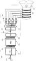
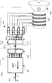
- FIG. 2 shows the configuration of a digital audio system using a digital speaker device according to a first embodiment of the present invention.
- the digital speaker device according to the present embodiment is configured of a device that outputs a plurality of digital signals from digital signals, and a driving device that drives a plurality of speaker driving elements by a plurality of digital signals output from the device.
- a parallel-serial conversion device and a serial-parallel conversion device connect between a device for outputting a plurality of digital signals and a drive device for driving a speaker drive element.
- the digital input signal (210) is input to the ⁇ modulator (201), and is converted into a plurality of n-bit digital signals (211) by the ⁇ modulator (201).
- the plurality of n-bit digital signals are converted to mismatched shaped m digital signals (212) by a post filter (202).
- the m digital signals are converted into digital signals (213) serially transmitted by the parallel-serial converter (203), and are converted back into m digital signals (214) by the serial-parallel converter (204).
- the number of bits of the serially transmitted digital signal (213) may be, for example, one, but is not limited to one.
- the speaker drive circuit (205) that has received the m digital signals (214) drives the s drive elements (206) to convert analog voice directly by the diaphragm (207).
- the ⁇ modulator (201), the post filter (202), and the parallel-serial converter (203) constitute an apparatus (200) for outputting a plurality of digital signals from digital signals.
- the serial-to-parallel converter (204) and the speaker drive circuit (205) constitute a drive device (220) for driving the speaker drive element.
- a device that outputs a plurality of digital signals from an input digital signal and a drive device that drives a speaker drive element by serial signals a plurality of digital signals are converted from digital signals. It becomes possible to connect the drive device which drives a plurality of speaker drive elements to the device to output by a serial signal. Therefore, even when a digital speaker device is used in, for example, a movie theater or a theater that uses a large number of speakers, it is possible to construct a digital sound system with a combination of simple devices as compared with conventional digital sound systems. This makes it possible to reduce the cost of the digital sound system.
- an example is shown in which an apparatus for outputting a plurality of digital signals from digital signals and a drive apparatus for driving a speaker drive element are electrically connected by serial signals.
- serial signals are transmitted by electromagnetic induction or electric field strength, such as connection with a wireless device or connection with an optical signal, is also present.
- the parallel signal (212) is converted into a plurality of serial signals by the parallel-serial converter (203) shown in FIG.
- the drive device for driving the speaker drive element by dividing the drive device for driving the speaker drive element into devices that output a plurality of digital signals from digital signals, it becomes possible to proceed with LSI implementation using device technology that is optimal for each device. As a result, the cost of the entire system can be reduced, and the operating voltage of the drive device for driving the speaker drive element can be increased. Therefore, it is possible to easily reproduce a loud volume without increasing the cost.
- FIG. 3 shows the configuration of a digital speaker device including a circuit that outputs a plurality of digital signals and a plurality of speaker driving elements according to a third embodiment of the present invention.
- the digital input signal (310) is input to the microcomputer device (301) and converted into m mismatch shaped digital signals (311).
- the m digital signals are converted into a 1-bit digital signal (312) by the parallel-serial converter (302), and are converted back into the m digital signals (313) by the serial-parallel converter (303).
- the speaker drive circuit (304) which has received the m digital signals (214) drives the s drive elements (305) to convert analog voice directly by the diaphragm (306).
- the microcomputer device (301) and the parallel-serial converter (302) constitute a device (300) for outputting a plurality of digital signals from digital signals
- the serial-parallel converter (303) and the speaker drive circuit And (304) constitute a drive unit (320).
- the speaker drive element is driven.
- the microcomputer device (301) has a processor, and the processor modulates the digital input signal and outputs an n-bit digital signal, and the ⁇ ⁇ modulator is connected to the ⁇ modulator to mismatch-shape the n-bit digital signal. Controlled by the program to operate as a post-filter to convert into m digital signals
- the ⁇ ⁇ ⁇ modulator and the post filter of the first embodiment are used. It is possible to program-process digital signal processing similar to the above. By processing the program, it is possible to update and improve the modulation characteristics of the ⁇ modulator and the filter characteristics of the post filter without changing the hardware.
- FIG. 4 shows a third embodiment of a system configuration of a digital speaker device including a plurality of circuits for outputting digital signals and a plurality of speaker driving elements.
- the digital input signal (410) is input to the microcomputer device (401) and converted into m mismatch shaped digital signals (411).
- the m digital signals are once recorded in the storage unit 312 by the format converter 402, and are converted back to m digital signals 413 by the format converter 403 again.
- the output of the format converter (402) may be converted into a digital signal serially transmitted by a parallel-serial converter, and the digital signal may be stored in the storage device (312).
- the digital signal read from the storage device (312) may be input to the serial-to-parallel converter and may be input to the format converter (403).
- the format converter (402) may include a parallel-serial converter
- the format converter (403) may include a serial-parallel converter.
- the speaker driving circuit (404) which has received the m digital signals (414) drives s driving elements (405) to directly convert analog sound by the diaphragm (406).
- the microcomputer device (401) and the format converter (402) constitute a device (400) for outputting a plurality of digital signals from digital signals.
- the format converter (403) and the speaker driving circuit (404) constitute a driving device (420) for driving the speaker driving element.
- the formatter converter (402) can also perform lossless data compression on m mismatch-shaped digital signals.
- the format converter (403) decompresses the data to reproduce the original m digital signals. By compressing the data in this manner, it is possible to significantly reduce the required capacity of the storage medium.
- FIG. 5 shows a fourth embodiment of a system configuration of a digital speaker device including a plurality of circuits for outputting digital signals and a plurality of speaker driving elements.
- the digital input signal (510) is input to the microcomputer device (501) and converted into m mismatch shaped digital signals (511).
- the m digital signals are once converted by the parallel-serial converter (502) into, for example, 1-bit digital signals (512) to be serially transmitted, and the m digital signals are converted again by the serial-parallel converter (503). It is returned to the signal (513).
- the speaker driving circuit (504) which has received the m digital signals (514) drives s driving elements (505) to convert analog voice directly by the diaphragm (506).
- the microcomputer device (501) and the parallel-serial converter (502) constitute a device (500) for outputting a plurality of digital signals from digital signals.
- the serial-to-parallel converter (503) and the speaker drive circuit (504) constitute a drive device (520) for driving the speaker drive element.
- the drive device (520) includes an ID element (521) storing the number and characteristics of the speaker drive circuit, and transmission means (522) for transmitting information from the ID element to a device (500) for outputting a plurality of digital signals. Install).
- the transmission means (522) transmits the information from the ID element (521) to the microcomputer device (501).
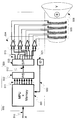
- FIG. 6 shows a fifth embodiment of a system configuration of a digital speaker device including a plurality of circuits for outputting digital signals and a plurality of speaker driving elements.
- a signal for driving a plurality of speaker driving elements is generated in advance by a device (600) for outputting a plurality of digital signals from digital signals, and a storage medium (storage medium) It is possible to save in (613). This makes it possible to distribute the converted data using a storage medium (613).
- the formatter converter (602) conventionally required by distributing the pre-converted data directly to the customer through the network, or recording and distributing the pre-converted data in a storage medium (storage medium). It is not necessary to prepare the device at the playback device side, and it is possible to provide the digital speaker device at a lower cost.
- Examples of storage media include media such as optical disks and memory cards. These media are preferably removable from the storage device. Therefore, these optical disks and memory cards may be attached to a drive device (620) as a stationary or portable reproduction device to perform reproduction. In the case of direct distribution to customers through the network, distribution may be performed in a stream format, or data distributed to a storage medium (storage medium) of the customer may be recorded once.
- the output from the device (600) for outputting a plurality of digital signals from the digital signal to the signals for driving the plurality of speaker drive elements is digitally modulated, it is difficult to restore the digital signal before the modulation. May be Thus, the output from the device (600) can have the same effect as being copy protected.
- the encryption and superimposition of the digital watermark data can be performed by, for example, the ⁇ modulator (601), the post filter (602) or the parallel-serial converter (603).
- the delta sigma modulator (601), the post filter (602) or the parallel-serial converter (603) may be equipped with an apparatus for encryption and superimposing of digital watermark data. Also, such devices may be independent devices.
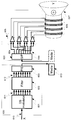
- FIG. 7 shows an embodiment in which a multi-bit internal quantizer is used as the internal quantizer of the cascode ⁇ ⁇ ⁇ modulator.
- a cascode ⁇ modulator 701
- a plurality of internal ⁇ modulators of the first stage and the second and subsequent stages are output.
- the plurality of n 1 -bit digital signals (711a) in the first stage are converted to mismatched shaped m 1 digital signals (712a) by the post filter (702a).
- the frequency characteristics are added to the second stage and subsequent n x outputs (711 b) by the post filter (702 b), and are further converted into m x mismatched shaped digital signals (712 b).
- the speaker driving circuit (705) that receives the m 1 + m 2 +... + M x digital signals (714) drives s driving elements (706) to convert analog voice directly by the diaphragm (707) Do.
- the cascode ⁇ modulator (701), the post filter (702a, b) and the parallel-serial converter (703) constitute a device (700) for outputting a plurality of digital signals from digital signals.
- the serial-to-parallel converter (704) and the speaker drive circuit (705) constitute a drive device (720) for driving the speaker drive element.
- the output of the second and subsequent stages is a code that cancels out the noise component included in the output of the first stage. Therefore, when the driving element (606) is less than m 1 + m 2 ... + m x may be also without using subsequent m 2 ... m x performed sufficiently high accuracy conversion.
- FIG. 8 shows the configuration of a digital speaker device provided with a circuit that outputs a plurality of digital signals and a plurality of speaker driving elements according to a seventh embodiment of the present invention.
- the digital input signal (810) is input to a digital signal processor (DSP) (801) and converted into m mismatched shaped digital signals (811).
- the m digital signals (811) are converted to s digital signals (812) by the parallel-serial converter (802), and are converted back to the m digital signals (813) by the serial-parallel converter (803).
- the speaker drive circuit (804) that has received the m digital signals (814) drives the s drive elements (805) to convert analog voice directly by the diaphragm (806).
- the relationship between the number of input digital signals and the number of output signals of the parallel-serial converter (802) is s ⁇ m, and s digital signals (812) are used for demodulation by the serial-parallel converter (803). It contains necessary information.
- the digital signal processor device (801) and the parallel-serial converter (802) constitute a device (800) for outputting a plurality of digital signals from digital signals, and the serial-parallel converter (803) and the speaker drive
- the circuit (804) constitutes a driving device (820). In the driving device (820), the speaker driving element is driven.
- a digital signal processor as a device for outputting a plurality of digital signals from an input digital signal, it has been performed in the ⁇ modulator and the post filter of the first embodiment Similar digital signal processing can be processed by a program. By processing the program, it is possible to update and improve the modulation characteristics of the ⁇ modulator and the filter characteristics of the post filter without changing the hardware.
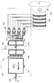
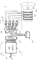
- FIG. 9 shows an eighth embodiment of a system configuration of a digital speaker device including a plurality of circuits for outputting digital signals and a plurality of speaker driving elements.
- the digital input signal (910) is input to a digital signal processor unit (microcomputer unit) (901) and converted into m mismatched shaped digital signals (811).
- the m digital signals are converted in format by the format converter (902) and output as information representing the m digital signals.
- the m digital signals output from the format converter (902) may be recorded once in the storage medium of the storage device (912) as shown in FIG. In this case, the conversion of the format by the format converter (902) is to convert into a format suitable for storage of the storage medium.
- the information representing the m digital signals recorded in the storage medium of the storage unit 912 is converted back into m digital signals 913 by the format converter 903 again.
- the speaker driving circuit 904 which has received the m digital signals 913 drives s driving elements 905 to convert analog voice directly by the diaphragm 906.
- the microcomputer device (901) and the format converter (902) constitute a device (900) for outputting a plurality of digital signals from digital signals.
- a format converter (903) and a speaker drive circuit (904) constitute a drive device (920) for driving a speaker drive element.
- m digital signals output from the format converter (902) may be output to a transmission line and transmitted.
- it may be transmitted by communication, or may be transmitted as broadcast simultaneously to a plurality of recipients.
- the transmission may be wireless or wired.
- the m digital signals are received and converted back to m digital signals (913) by the format converter (903). The subsequent processing is as described above.
- any kind of digital format that can be converted reversibly can be used.
- a device for outputting a plurality of digital signals from digital signals and a drive device for driving a speaker drive element can be connected by a storage device or a transmission path.
- a storage device when a storage device is used, real-time processing of voice reproduction can not be performed.
- a digital signal processor device having a slow processing speed it is performed by the ⁇ modulator and the post filter of the first embodiment. Since it becomes possible to programmatically process digital signal processing similar to the matter, it is possible to realize a digital audio system with lower power consumption than conventional digital audio systems.
- the format converter (902) can perform lossless data compression on m mismatch-shaped digital signals.
- the format converter (903) decompresses the data and reproduces the original m digital signals. By compressing the data in this manner, it is possible to significantly reduce the required capacity of the storage medium.
- the number of coils in the digital speaker unit can be changed.
- data is generated in advance, but since the number of coils used on the reproduction side can be selected, there is no need to prepare data corresponding to the number of coils in advance. It is possible to reduce the amount of data.
Landscapes
- Engineering & Computer Science (AREA)
- Physics & Mathematics (AREA)
- Signal Processing (AREA)
- Acoustics & Sound (AREA)
- Theoretical Computer Science (AREA)
- Multimedia (AREA)
- General Physics & Mathematics (AREA)
- General Engineering & Computer Science (AREA)
- Databases & Information Systems (AREA)
- Data Mining & Analysis (AREA)
- Power Engineering (AREA)
- Circuit For Audible Band Transducer (AREA)
- Analogue/Digital Conversion (AREA)
- Computational Linguistics (AREA)
- Health & Medical Sciences (AREA)
- Audiology, Speech & Language Pathology (AREA)
- Human Computer Interaction (AREA)
Abstract
Description
図2に本発明の第1の実施形態に係る、デジタルスピーカー装置を使ったデジタル音響システムの構成を示す。本実施形態に係るデジタルスピーカー装置は、デジタル信号から複数のデジタル信号を出力する装置と、この装置が出力する複数のデジタル信号により複数のスピーカー駆動素子を駆動する駆動装置で構成される。本実施形態の特徴の一つは、複数のデジタル信号を出力する装置とスピーカー駆動素子を駆動する駆動装置の間をパラレル・シリアル変換装置とシリアル・パラレル変換装置により接続する点である。
図3に、本発明の第3の実施形態に係る、複数のデジタル信号を出力する回路と複数のスピーカー駆動素子とを備えるデジタルスピーカー装置の構成を示す。デジタル入力信号(310)はマイクロコンピューター装置(301)に入力されミスマッチシェーピングされたm個のデジタル信号(311)に変換される。m個のデジタル信号は、パラレル・シリアル変換器(302)で1ビットのデジタル信号(312)に変換され、シリアル・パラレル変換器(303)でm個のデジタル信号(313)に戻される。m個のデジタル信号(214)を受け取ったスピーカー駆動回路(304)はs個の駆動素子(305)を駆動してアナログ音声を振動膜(306)により直接変換する。
ロセッサを有し、プロセッサは、デジタル入力信号を変調しnビットのデジタル信号を出力するΔΣ変調器と、ΔΣ変調器に接続されnビットのデジタル信号をミスマッチシェーピングしm個のデジタル信号に変換する後置フィルターとして、動作させるためのプログラムにより、制御される
図4に複数のデジタル信号を出力する回路と複数のスピーカー駆動素子からなるデジタルスピーカー装置のシステム形態の第3の実施形態を示す。デジタル入力信号(410)はマイクロコンピューター装置(401)に入力されミスマッチシェーピングされたm個のデジタル信号(411)に変換される。m個のデジタル信号は、フォーマット変換器(402)で記憶装置(312)に一度記録され、再度フォーマット変換器(403)でm個のデジタル信号(413)に戻される。なお、フォーマット変換器(402)の出力をパラレル・シリアル変換器によりシリアル伝送されるデジタル信号に変換し、記憶装置(312)にデジタル信号を記憶してもよい。また、記憶装置(312)から読み出されたデジタル信号は、シリアル・パラレル変換器に入力され、フォーマット変換器(403)に入力されてもよい。また、フォーマット変換器(402)がパラレル・シリアル変換器を含み、フォーマット変換器(403)がシリアル・パラレル変換器を含む構成でもよい。
図5に複数のデジタル信号を出力する回路と複数のスピーカー駆動素子からなるデジタルスピーカー装置のシステム形態の第4の実施形態を示す。デジタル入力信号(510)はマイクロコンピューター装置(501)に入力されミスマッチシェーピングされたm個のデジタル信号(511)に変換される。m個のデジタル信号は、パラレル・シリアル変換器(502)で、シリアル伝送される例えば1ビットのデジタル信号(512)に、一旦変換され、再度シリアル・パラレル変換器(503)でm個のデジタル信号(513)に戻される。前記m個のデジタル信号(514)を受け取ったスピーカー駆動回路(504)はs個の駆動素子(505)を駆動してアナログ音声を振動膜(506)により直接変換する。ここで、マイクロコンピューター装置(501)とパラレル・シリアル変換器(502)とが、デジタル信号から複数のデジタル信号を出力する装置(500)を構成している。また、シリアル・パラレル変換器(503)とスピーカー駆動回路(504)とがスピーカー駆動素子を駆動する駆動装置(520)を構成している。更に駆動装置(520)はスピーカー駆動回路の個数や特性を記憶したID素子(521)を備え、そのID素子からの情報を、複数のデジタル信号を出力する装置(500)に伝える伝送手段(522)を設置する。伝送手段(522)は、マイクロコンピューター装置(501)にID素子(521)からの情報を伝送する。
処理をプログラムにより対応することが可能になるので、異なる駆動装置を一つの複数のデジタル信号を出力する装置に接続することが可能になる。
図6に複数のデジタル信号を出力する回路と複数のスピーカー駆動素子からなるデジタルスピーカー装置のシステム形態の第5の実施形態を示す。図4に示した第3の実施形態と同じように、あらかじめ複数のスピーカー駆動素子を駆動する信号をデジタル信号から複数のデジタル信号を出力する装置(600)により生成して保存メディア(記憶媒体)(613)に保存しておくことが可能である。これにより変換されたデータを、保存メディア(613)を使って流通させることが可能となる。このあらかじめ変換されたデータをネットワーク通じて直接顧客に配信したり、あらかじめ変換されたデータを保存メディア(記憶媒体)に記録し流通させたりすることにより、従来必要であったフォーマッタ変換器(602)を、再生する装置側で用意する必要がなくなり、デジタルスピーカー装置をより廉価に提供することが可能となる。
実施形態1から5におけるΔΣ変調器にカスコード型ΔΣ変調器を用いることも可能である。図7にカスコード型ΔΣ変調器の内部量子化器に多ビットのものを用いた場合の実施形態を示す。カスコード型ΔΣ変調器(701)では、初段および2段目以降の複数の内部ΔΣ変調器が出力される。初段のn1ビットの複数のデジタル信号(711a)は後置フィルター(702a)でミスマッチシェーピングされたm1個のデジタル信号(712a)に変換される。2段目以降のnx出力(711b)には後置フィルタ(702b)で周波数特性を付加し、さらにミスマッチシェーピングされたmx個のデジタル信号(712b)に変換される。
図8に、本発明の第7の実施形態に係る、複数のデジタル信号を出力する回路と複数のスピーカー駆動素子とを備えるデジタルスピーカー装置の構成を示す。デジタル入力信号(810)はデジタルシグナルプロセッサー装置(DSP)(801)に入力されミスマッチシェーピングされたm個のデジタル信号(811)に変換される。m個のデジタル信号(811)は、パラレル・シリアル変換器(802)でs個のデジタル信号(812)に変換され、シリアル・パラレル変換器(803)でm個のデジタル信号(813)に戻される。m個のデジタル信号(814)を受け取ったスピーカー駆動回路(804)はs個の駆動素子(805)を駆動してアナログ音声を振動膜(806)により直接変換する。
図9に複数のデジタル信号を出力する回路と複数のスピーカー駆動素子からなるデジタルスピーカー装置のシステム形態の第8の実施形態を示す。デジタル入力信号(910)はデジタルシグナルプロセッサ装置(マイクロコンピュータ装置)(901)に入力されミスマッチシェーピングされたm個のデジタル信号(811)に変換される。m個のデジタル信号は、フォーマット変換器(902)でフォーマットが変換されてm個のデジタル信号を表わす情報として出力される。フォーマット変換器(902)から出力されるm個のデジタル信号は、図9に示すように記憶装置(912)の記憶媒体に一度記録されてもよい。この場合、フォーマット変換器(902)によるフォーマットの変換は、記憶媒体の記憶に適したフォーマットに変換することである。記憶装置(912)の記憶媒体に記録されたm個のデジタル信号を表わす情報は、再度フォーマット変換器(903)でm個のデジタル信号(913)に戻される。前記m個のデジタル信号(913)を受け取ったスピーカー駆動回路(904)はs個の駆動素子(905)を駆動してアナログ音声を振動膜(906)により直接変換する。ここで、マイクロコンピューター装置(901)とフォーマット変換器(902)とが、デジタル信号から複数のデジタル信号を出力する装置(900)を構成している。また、フォーマット変換器(903)とスピーカー駆動回路(904)とがスピーカー駆動素子を駆動する駆動装置(920)を構成している。
Claims (22)
- デジタル入力信号を変調しnビットのデジタル信号を出力するΔΣ変調器と、
前記ΔΣ変調器に接続され前記nビットのデジタル信号をミスマッチシェーピングしm個のデジタル信号に変換する後置フィルターと、
前記後置フィルターが変換したm個のデジタル信号をシリアル伝送されるデジタル信号に変換するパラレル・シリアル変換器と、
前記パラレル・シリアル変換器により変換されたデジタル信号をm個のデジタル信号に変換し復元するシリアル・パラレル変換器と、
前記シリアル・パラレル変換器により復元されたm個のデジタル信号を受け取り、s個の駆動素子を駆動してアナログ音声に変換する駆動回路と
を有するデジタル音響システム。 - 前記シリアル伝送されるデジタル信号のビット数が1であることを特徴とする請求項1に記載のデジタル音響システム。
- 前記パラレル・シリアル変換器により変換されたデジタル信号を記憶し、記憶されたデジタル信号を読み出して前記シリアル・パラレル変換器に出力する記憶装置を有する請求項1または2に記載のデジタル音響システム。
- 前記記憶装置は、着脱可能な記憶媒体に前記パラレル・シリアル変換器により変換されたデジタル信号を記憶し、読み出すことが可能であることを特徴とする請求項3に記載のデジタル音響システム。
- 前記記憶装置は、電子透かしデータが重畳されたデータを記憶することを特徴とする請求項3または4に記載のデジタル音響システム。
- 前記電子透かしデータは、前記アナログ音声の帯域外のデータとして重畳されることを特徴とする請求項5に記載のデジタル音響システム。
- デジタル入力信号をm個のデジタル信号に変換するプロセッサと、
前記プロセッサが変換したm個のデジタル信号をシリアル伝送されるデジタル信号に変換するパラレル・シリアル変換器と、
前記パラレル・シリアル変換器により変換されたデジタル信号をm個のデジタル信号に変換し復元するシリアル・パラレル変換器と、
前記シリアル・パラレル変換器により復元されたm個のデジタル信号を受け取り、s個の駆動素子を駆動してアナログ音声に変換する駆動回路と
を有し、
前記プロセッサは、前記プロセッサを、デジタル入力信号を変調しnビットのデジタル信号を出力するΔΣ変調器と、前記ΔΣ変調器に接続され前記nビットのデジタル信号をミスマッチシェーピングしm個のデジタル信号に変換する後置フィルターとして、動作させるためのプログラムにより、制御されることを特徴とするデジタル音響システム。 - 前記駆動素子の数を記憶する素子を有し、
前記プログラムは、前記素子に記憶された前記駆動素子の数を読み取り、前記プロセッサを制御することを特徴とする請求項7に記載のデジタル音響システム。 - 前記プロセッサはデジタルシグナルプロセッサである請求項7または8に記載のデジタル音響システム。
- 前記パラレル・シリアル変換器の出力する信号の個数は、前記パラレル・シリアル変換器に入力される信号の個数より小さく、前記パラレル・シリアル変換器の出力する信号は、前記シリアル・パラレル変換器での復調に必要な情報を含む請求項7から9のいずれかに記載のデジタル音響システム。
- デジタル入力信号をm個のデジタル信号に変換するデジタルシグナルプロセッサと、
前記デジタルプロセッサが変換したm個のデジタル信号のフォーマットを変換して記憶媒体に記憶するフォーマット変換器と
を有し、
前記デジタルシグナルプロセッサは、前記プロセッサを、デジタル入力信号を変調しnビットのデジタル
信号を出力するΔΣ変調器と、前記ΔΣ変調器に接続され前記nビットのデジタル信号をミスマッチシェーピングしm個のデジタル信号に変換して出力する後置フィルターとして、動作させるためのプログラムにより、制御されることを特徴とするデジタル音響システム。 - 前記フォーマット変換器によるフォーマットの変換は可逆変換である請求項11に記載のデジタル音響システム。
- 前記フォーマット変換器によるフォーマットの変換はデータ圧縮を含む請求項11に記載のデジタル音響システム。
- 前記後置フィルターは、記憶媒体又は伝送路に出力を行う請求項11から13のいずれかに記載の音響システム。
- デジタル入力信号を変調するΔΣ変調器の出力をミスマッチシェーピングする後置フィルターが出力したデジタル信号を記憶した記録媒体から前記デジタル信号を読み取り、駆動素子を駆動してアナログ音声に変換する駆動回路を有するデジタル再生装置。
- 前記記録媒体が記憶するデジタル信号には、前記駆動回路の駆動素子の数が含まれることを特徴とする請求項15に記載のデジタル再生装置。
- 前記記録媒体が記憶するデジタル信号には、電子透かしデータが重畳されたデータを記憶することを特徴とする請求項15または16に記載のデジタル再生装置。
- 電子透かしデータは、前記アナログ音声の帯域外のデータとして重畳されることを特徴とする請求項17に記載のデジタル再生装置。
- デジタル入力信号を変調するΔΣ変調器の出力をミスマッチシェーピングする後置フィルターが出力したデジタル信号を受信し、駆動素子を駆動してアナログ音声に変換する駆動回路を有するデジタル再生装置。
- 前記受信されるデジタル信号には、前記駆動回路の駆動素子の数が含まれることを特徴とする請求項19に記載のデジタル再生装置。
- 前記受信されるデジタル信号には、電子透かしデータが重畳されたデータを記憶することを特徴とする請求項19または20に記載のデジタル再生装置。
- 電子透かしデータは、前記アナログ音声の帯域外のデータとして重畳されることを特徴とする請求項21に記載のデジタル再生装置。
Priority Applications (6)
| Application Number | Priority Date | Filing Date | Title |
|---|---|---|---|
| JP2013540824A JP6169971B2 (ja) | 2011-10-25 | 2012-10-25 | デジタル音響システム |
| EP12843176.4A EP2782361A4 (en) | 2011-10-25 | 2012-10-25 | DIGITAL ACOUSTIC SYSTEM |
| KR1020147009605A KR20140079400A (ko) | 2011-10-25 | 2012-10-25 | 디지털 음향 시스템 |
| CN201280052756.XA CN103891312B (zh) | 2011-10-25 | 2012-10-25 | 数字音响系统 |
| IN3351DEN2014 IN2014DN03351A (ja) | 2011-10-25 | 2012-10-25 | |
| US14/260,793 US9793868B2 (en) | 2011-10-25 | 2014-04-24 | Digital acoustic system |
Applications Claiming Priority (2)
| Application Number | Priority Date | Filing Date | Title |
|---|---|---|---|
| JP2011233937 | 2011-10-25 | ||
| JP2011-233937 | 2011-10-25 |
Related Child Applications (1)
| Application Number | Title | Priority Date | Filing Date |
|---|---|---|---|
| US14/260,793 Continuation US9793868B2 (en) | 2011-10-25 | 2014-04-24 | Digital acoustic system |
Publications (1)
| Publication Number | Publication Date |
|---|---|
| WO2013062038A1 true WO2013062038A1 (ja) | 2013-05-02 |
Family
ID=48167864
Family Applications (1)
| Application Number | Title | Priority Date | Filing Date |
|---|---|---|---|
| PCT/JP2012/077570 WO2013062038A1 (ja) | 2011-10-25 | 2012-10-25 | デジタル音響システム |
Country Status (7)
| Country | Link |
|---|---|
| US (1) | US9793868B2 (ja) |
| EP (1) | EP2782361A4 (ja) |
| JP (1) | JP6169971B2 (ja) |
| KR (1) | KR20140079400A (ja) |
| CN (1) | CN103891312B (ja) |
| IN (1) | IN2014DN03351A (ja) |
| WO (1) | WO2013062038A1 (ja) |
Families Citing this family (2)
| Publication number | Priority date | Publication date | Assignee | Title |
|---|---|---|---|---|
| JP6648821B2 (ja) * | 2016-04-15 | 2020-02-14 | 第一精工株式会社 | スピーカシステム |
| EP3355590A1 (en) * | 2017-01-26 | 2018-08-01 | Vestel Elektronik Sanayi ve Ticaret A.S. | Loudspeaker, apparatus comprising the same, and method of operating a loudspeaker |
Citations (4)
| Publication number | Priority date | Publication date | Assignee | Title |
|---|---|---|---|---|
| JP2005311847A (ja) * | 2004-04-23 | 2005-11-04 | Nippon Telegr & Teleph Corp <Ntt> | データ通信方法、データ送信装置およびデータ受信装置、ならびにデータ送信プログラム |
| JP2006197152A (ja) * | 2005-01-13 | 2006-07-27 | Sharp Corp | 骨伝導スピーカ装置 |
| JP2009010820A (ja) * | 2007-06-29 | 2009-01-15 | Sony Corp | 記憶装置、記憶制御方法、およびプログラム |
| WO2011074341A1 (ja) * | 2009-12-16 | 2011-06-23 | 株式会社 Trigence Semiconductor | 音響システム |
Family Cites Families (9)
| Publication number | Priority date | Publication date | Assignee | Title |
|---|---|---|---|---|
| JP3341566B2 (ja) * | 1996-02-15 | 2002-11-05 | ソニー株式会社 | 信号伝送方法及び装置、並びに信号再生方法及び装置 |
| JP3415398B2 (ja) * | 1997-08-07 | 2003-06-09 | パイオニア株式会社 | 音声信号処理装置 |
| JP4061791B2 (ja) * | 1999-10-29 | 2008-03-19 | ヤマハ株式会社 | デジタルデータ再生装置 |
| JP2002176362A (ja) * | 2000-12-06 | 2002-06-21 | Sony Corp | ディジタル信号伝送方法及び装置 |
| US7058463B1 (en) * | 2000-12-29 | 2006-06-06 | Nokia Corporation | Method and apparatus for implementing a class D driver and speaker system |
| WO2005002200A2 (en) * | 2003-06-13 | 2005-01-06 | Nielsen Media Research, Inc. | Methods and apparatus for embedding watermarks |
| KR101341761B1 (ko) | 2006-05-21 | 2013-12-13 | 트라이젠스 세미컨덕터 가부시키가이샤 | 디지털 아날로그 변환장치 |
| JP5396588B2 (ja) | 2008-06-16 | 2014-01-22 | 株式会社 Trigence Semiconductor | デジタルスピーカー駆動装置,デジタルスピーカー装置,アクチュエータ,平面ディスプレイ装置及び携帯電子機器 |
| CN101944360A (zh) * | 2009-07-03 | 2011-01-12 | 邱剑 | 方便使用的方法和终端 |
-
2012
- 2012-10-25 JP JP2013540824A patent/JP6169971B2/ja not_active Expired - Fee Related
- 2012-10-25 EP EP12843176.4A patent/EP2782361A4/en not_active Withdrawn
- 2012-10-25 IN IN3351DEN2014 patent/IN2014DN03351A/en unknown
- 2012-10-25 CN CN201280052756.XA patent/CN103891312B/zh not_active Expired - Fee Related
- 2012-10-25 WO PCT/JP2012/077570 patent/WO2013062038A1/ja active Application Filing
- 2012-10-25 KR KR1020147009605A patent/KR20140079400A/ko not_active Application Discontinuation
-
2014
- 2014-04-24 US US14/260,793 patent/US9793868B2/en active Active
Patent Citations (8)
| Publication number | Priority date | Publication date | Assignee | Title |
|---|---|---|---|---|
| JP2005311847A (ja) * | 2004-04-23 | 2005-11-04 | Nippon Telegr & Teleph Corp <Ntt> | データ通信方法、データ送信装置およびデータ受信装置、ならびにデータ送信プログラム |
| JP2006197152A (ja) * | 2005-01-13 | 2006-07-27 | Sharp Corp | 骨伝導スピーカ装置 |
| JP2009010820A (ja) * | 2007-06-29 | 2009-01-15 | Sony Corp | 記憶装置、記憶制御方法、およびプログラム |
| WO2011074341A1 (ja) * | 2009-12-16 | 2011-06-23 | 株式会社 Trigence Semiconductor | 音響システム |
| US20110160883A1 (en) * | 2009-12-16 | 2011-06-30 | Trigence Semiconductor, Inc. | Acoustic playback system |
| CN102239706A (zh) * | 2009-12-16 | 2011-11-09 | 株式会社特瑞君思半导体 | 音响系统 |
| KR20120101186A (ko) * | 2009-12-16 | 2012-09-13 | 트라이젠스 세미컨덕터 가부시키가이샤 | 음향 시스템 |
| EP2515555A1 (en) * | 2009-12-16 | 2012-10-24 | Trigence Semiconductor, Inc. | Acoustic system |
Non-Patent Citations (1)
| Title |
|---|
| See also references of EP2782361A4 * |
Also Published As
| Publication number | Publication date |
|---|---|
| CN103891312B (zh) | 2017-09-01 |
| US9793868B2 (en) | 2017-10-17 |
| EP2782361A1 (en) | 2014-09-24 |
| KR20140079400A (ko) | 2014-06-26 |
| JPWO2013062038A1 (ja) | 2015-04-02 |
| CN103891312A (zh) | 2014-06-25 |
| US20140236332A1 (en) | 2014-08-21 |
| IN2014DN03351A (ja) | 2015-06-26 |
| EP2782361A4 (en) | 2015-07-08 |
| JP6169971B2 (ja) | 2017-07-26 |
Similar Documents
| Publication | Publication Date | Title |
|---|---|---|
| JP4883428B2 (ja) | デジタルアナログ変換装置 | |
| EP2859548B1 (en) | Doubly compatible lossless audio bandwidth extension | |
| JP5158820B2 (ja) | サラウンド・サウンド・システムの低域効果およびサラウンド・チャネルの無線ディジタル伝送 | |
| JP3272438B2 (ja) | 信号処理システムおよび処理方法 | |
| Watkinson | The art of sound reproduction | |
| JPH11502981A (ja) | スピーカーの、またはスピーカーに関する改善 | |
| US6714825B1 (en) | Multi-channel audio reproducing device | |
| JP3468183B2 (ja) | 音声再生記録装置および方法 | |
| CN105869647B (zh) | 一种智能手机原生dsd音频解码方法、系统及智能手机 | |
| WO2013062038A1 (ja) | デジタル音響システム | |
| Janssen et al. | Super-audio CD: an introduction | |
| KR100372904B1 (ko) | 신호 처리 장치 | |
| JP3304750B2 (ja) | ロスレス符号装置とロスレス記録媒体とロスレス復号装置とロスレス符号復号装置 | |
| JP2009033649A (ja) | コンテンツデータ送受信システム、コンテンツデータ送信装置、コンテンツデータ受信装置、コンテンツデータ送信方法、コンテンツデータ受信処理方法 | |
| EP0890949A2 (en) | Digital audio processing system compatible with digital versatile disk video standard | |
| JP4209192B2 (ja) | 音声再生出力システム、音声信号再生装置、音声出力駆動装置、ヘッドホン | |
| JP2018110362A (ja) | オーディオ信号処理回路、それを用いた車載オーディオシステム、オーディオコンポーネント装置、電子機器、オーディオ信号処理方法 | |
| JP2006079742A (ja) | 情報処理装置および方法、並びにプログラム | |
| Hawksford | High-definition digital audio in 3-dimensional sound reproduction | |
| CN111078182A (zh) | 一种基于Android的音乐高保真无损播放系统及音乐播放方法 | |
| WO2003088075A1 (en) | Redbook encoding/decoding conversion device | |
| JP2008244775A (ja) | オーディオ回路およびそれを備える電子機器 | |
| Ausiello | Two-and-Three level representation of analog and digital signals by means of advanced sigma-delta modulation | |
| KR20030080199A (ko) | 데이터를 자동으로 변환하고 재생하기 위해 레드북 포맷의데이터와 옐로우북 포맷의 코드를 포함하는 cd | |
| JPH02262710A (ja) | デジタル信号処理装置と光学記録装置とデジタル信号再生装置とデジタル信号送信装置とデジタル信号受信装置 |
Legal Events
| Date | Code | Title | Description |
|---|---|---|---|
| 121 | Ep: the epo has been informed by wipo that ep was designated in this application |
Ref document number: 12843176 Country of ref document: EP Kind code of ref document: A1 |
|
| ENP | Entry into the national phase |
Ref document number: 20147009605 Country of ref document: KR Kind code of ref document: A |
|
| ENP | Entry into the national phase |
Ref document number: 2013540824 Country of ref document: JP Kind code of ref document: A |
|
| NENP | Non-entry into the national phase |
Ref country code: DE |
|
| WWE | Wipo information: entry into national phase |
Ref document number: 2012843176 Country of ref document: EP |