WO2013061400A1 - 車両用充電装置 - Google Patents
車両用充電装置 Download PDFInfo
- Publication number
- WO2013061400A1 WO2013061400A1 PCT/JP2011/074486 JP2011074486W WO2013061400A1 WO 2013061400 A1 WO2013061400 A1 WO 2013061400A1 JP 2011074486 W JP2011074486 W JP 2011074486W WO 2013061400 A1 WO2013061400 A1 WO 2013061400A1
- Authority
- WO
- WIPO (PCT)
- Prior art keywords
- actuator
- side connector
- power supply
- vehicle
- locking
- Prior art date
Links
Images


Classifications
-
- B—PERFORMING OPERATIONS; TRANSPORTING
- B60—VEHICLES IN GENERAL
- B60L—PROPULSION OF ELECTRICALLY-PROPELLED VEHICLES; SUPPLYING ELECTRIC POWER FOR AUXILIARY EQUIPMENT OF ELECTRICALLY-PROPELLED VEHICLES; ELECTRODYNAMIC BRAKE SYSTEMS FOR VEHICLES IN GENERAL; MAGNETIC SUSPENSION OR LEVITATION FOR VEHICLES; MONITORING OPERATING VARIABLES OF ELECTRICALLY-PROPELLED VEHICLES; ELECTRIC SAFETY DEVICES FOR ELECTRICALLY-PROPELLED VEHICLES
- B60L53/00—Methods of charging batteries, specially adapted for electric vehicles; Charging stations or on-board charging equipment therefor; Exchange of energy storage elements in electric vehicles
- B60L53/10—Methods of charging batteries, specially adapted for electric vehicles; Charging stations or on-board charging equipment therefor; Exchange of energy storage elements in electric vehicles characterised by the energy transfer between the charging station and the vehicle
- B60L53/14—Conductive energy transfer
-
- B—PERFORMING OPERATIONS; TRANSPORTING
- B60—VEHICLES IN GENERAL
- B60L—PROPULSION OF ELECTRICALLY-PROPELLED VEHICLES; SUPPLYING ELECTRIC POWER FOR AUXILIARY EQUIPMENT OF ELECTRICALLY-PROPELLED VEHICLES; ELECTRODYNAMIC BRAKE SYSTEMS FOR VEHICLES IN GENERAL; MAGNETIC SUSPENSION OR LEVITATION FOR VEHICLES; MONITORING OPERATING VARIABLES OF ELECTRICALLY-PROPELLED VEHICLES; ELECTRIC SAFETY DEVICES FOR ELECTRICALLY-PROPELLED VEHICLES
- B60L3/00—Electric devices on electrically-propelled vehicles for safety purposes; Monitoring operating variables, e.g. speed, deceleration or energy consumption
- B60L3/0023—Detecting, eliminating, remedying or compensating for drive train abnormalities, e.g. failures within the drive train
- B60L3/0069—Detecting, eliminating, remedying or compensating for drive train abnormalities, e.g. failures within the drive train relating to the isolation, e.g. ground fault or leak current
-
- B—PERFORMING OPERATIONS; TRANSPORTING
- B60—VEHICLES IN GENERAL
- B60L—PROPULSION OF ELECTRICALLY-PROPELLED VEHICLES; SUPPLYING ELECTRIC POWER FOR AUXILIARY EQUIPMENT OF ELECTRICALLY-PROPELLED VEHICLES; ELECTRODYNAMIC BRAKE SYSTEMS FOR VEHICLES IN GENERAL; MAGNETIC SUSPENSION OR LEVITATION FOR VEHICLES; MONITORING OPERATING VARIABLES OF ELECTRICALLY-PROPELLED VEHICLES; ELECTRIC SAFETY DEVICES FOR ELECTRICALLY-PROPELLED VEHICLES
- B60L3/00—Electric devices on electrically-propelled vehicles for safety purposes; Monitoring operating variables, e.g. speed, deceleration or energy consumption
- B60L3/04—Cutting off the power supply under fault conditions
-
- B—PERFORMING OPERATIONS; TRANSPORTING
- B60—VEHICLES IN GENERAL
- B60L—PROPULSION OF ELECTRICALLY-PROPELLED VEHICLES; SUPPLYING ELECTRIC POWER FOR AUXILIARY EQUIPMENT OF ELECTRICALLY-PROPELLED VEHICLES; ELECTRODYNAMIC BRAKE SYSTEMS FOR VEHICLES IN GENERAL; MAGNETIC SUSPENSION OR LEVITATION FOR VEHICLES; MONITORING OPERATING VARIABLES OF ELECTRICALLY-PROPELLED VEHICLES; ELECTRIC SAFETY DEVICES FOR ELECTRICALLY-PROPELLED VEHICLES
- B60L53/00—Methods of charging batteries, specially adapted for electric vehicles; Charging stations or on-board charging equipment therefor; Exchange of energy storage elements in electric vehicles
- B60L53/10—Methods of charging batteries, specially adapted for electric vehicles; Charging stations or on-board charging equipment therefor; Exchange of energy storage elements in electric vehicles characterised by the energy transfer between the charging station and the vehicle
- B60L53/14—Conductive energy transfer
- B60L53/16—Connectors, e.g. plugs or sockets, specially adapted for charging electric vehicles
-
- B—PERFORMING OPERATIONS; TRANSPORTING
- B60—VEHICLES IN GENERAL
- B60L—PROPULSION OF ELECTRICALLY-PROPELLED VEHICLES; SUPPLYING ELECTRIC POWER FOR AUXILIARY EQUIPMENT OF ELECTRICALLY-PROPELLED VEHICLES; ELECTRODYNAMIC BRAKE SYSTEMS FOR VEHICLES IN GENERAL; MAGNETIC SUSPENSION OR LEVITATION FOR VEHICLES; MONITORING OPERATING VARIABLES OF ELECTRICALLY-PROPELLED VEHICLES; ELECTRIC SAFETY DEVICES FOR ELECTRICALLY-PROPELLED VEHICLES
- B60L53/00—Methods of charging batteries, specially adapted for electric vehicles; Charging stations or on-board charging equipment therefor; Exchange of energy storage elements in electric vehicles
- B60L53/30—Constructional details of charging stations
- B60L53/305—Communication interfaces
-
- H—ELECTRICITY
- H01—ELECTRIC ELEMENTS
- H01R—ELECTRICALLY-CONDUCTIVE CONNECTIONS; STRUCTURAL ASSOCIATIONS OF A PLURALITY OF MUTUALLY-INSULATED ELECTRICAL CONNECTING ELEMENTS; COUPLING DEVICES; CURRENT COLLECTORS
- H01R13/00—Details of coupling devices of the kinds covered by groups H01R12/70 or H01R24/00 - H01R33/00
- H01R13/62—Means for facilitating engagement or disengagement of coupling parts or for holding them in engagement
- H01R13/639—Additional means for holding or locking coupling parts together, after engagement, e.g. separate keylock, retainer strap
-
- H—ELECTRICITY
- H01—ELECTRIC ELEMENTS
- H01R—ELECTRICALLY-CONDUCTIVE CONNECTIONS; STRUCTURAL ASSOCIATIONS OF A PLURALITY OF MUTUALLY-INSULATED ELECTRICAL CONNECTING ELEMENTS; COUPLING DEVICES; CURRENT COLLECTORS
- H01R13/00—Details of coupling devices of the kinds covered by groups H01R12/70 or H01R24/00 - H01R33/00
- H01R13/66—Structural association with built-in electrical component
- H01R13/70—Structural association with built-in electrical component with built-in switch
- H01R13/701—Structural association with built-in electrical component with built-in switch the switch being actuated by an accessory, e.g. cover, locking member
-
- B—PERFORMING OPERATIONS; TRANSPORTING
- B60—VEHICLES IN GENERAL
- B60L—PROPULSION OF ELECTRICALLY-PROPELLED VEHICLES; SUPPLYING ELECTRIC POWER FOR AUXILIARY EQUIPMENT OF ELECTRICALLY-PROPELLED VEHICLES; ELECTRODYNAMIC BRAKE SYSTEMS FOR VEHICLES IN GENERAL; MAGNETIC SUSPENSION OR LEVITATION FOR VEHICLES; MONITORING OPERATING VARIABLES OF ELECTRICALLY-PROPELLED VEHICLES; ELECTRIC SAFETY DEVICES FOR ELECTRICALLY-PROPELLED VEHICLES
- B60L2250/00—Driver interactions
- B60L2250/10—Driver interactions by alarm
-
- B—PERFORMING OPERATIONS; TRANSPORTING
- B60—VEHICLES IN GENERAL
- B60L—PROPULSION OF ELECTRICALLY-PROPELLED VEHICLES; SUPPLYING ELECTRIC POWER FOR AUXILIARY EQUIPMENT OF ELECTRICALLY-PROPELLED VEHICLES; ELECTRODYNAMIC BRAKE SYSTEMS FOR VEHICLES IN GENERAL; MAGNETIC SUSPENSION OR LEVITATION FOR VEHICLES; MONITORING OPERATING VARIABLES OF ELECTRICALLY-PROPELLED VEHICLES; ELECTRIC SAFETY DEVICES FOR ELECTRICALLY-PROPELLED VEHICLES
- B60L2270/00—Problem solutions or means not otherwise provided for
- B60L2270/30—Preventing theft during charging
- B60L2270/32—Preventing theft during charging of electricity
-
- B—PERFORMING OPERATIONS; TRANSPORTING
- B60—VEHICLES IN GENERAL
- B60L—PROPULSION OF ELECTRICALLY-PROPELLED VEHICLES; SUPPLYING ELECTRIC POWER FOR AUXILIARY EQUIPMENT OF ELECTRICALLY-PROPELLED VEHICLES; ELECTRODYNAMIC BRAKE SYSTEMS FOR VEHICLES IN GENERAL; MAGNETIC SUSPENSION OR LEVITATION FOR VEHICLES; MONITORING OPERATING VARIABLES OF ELECTRICALLY-PROPELLED VEHICLES; ELECTRIC SAFETY DEVICES FOR ELECTRICALLY-PROPELLED VEHICLES
- B60L2270/00—Problem solutions or means not otherwise provided for
- B60L2270/30—Preventing theft during charging
- B60L2270/34—Preventing theft during charging of parts
-
- Y—GENERAL TAGGING OF NEW TECHNOLOGICAL DEVELOPMENTS; GENERAL TAGGING OF CROSS-SECTIONAL TECHNOLOGIES SPANNING OVER SEVERAL SECTIONS OF THE IPC; TECHNICAL SUBJECTS COVERED BY FORMER USPC CROSS-REFERENCE ART COLLECTIONS [XRACs] AND DIGESTS
- Y02—TECHNOLOGIES OR APPLICATIONS FOR MITIGATION OR ADAPTATION AGAINST CLIMATE CHANGE
- Y02T—CLIMATE CHANGE MITIGATION TECHNOLOGIES RELATED TO TRANSPORTATION
- Y02T10/00—Road transport of goods or passengers
- Y02T10/60—Other road transportation technologies with climate change mitigation effect
- Y02T10/70—Energy storage systems for electromobility, e.g. batteries
-
- Y—GENERAL TAGGING OF NEW TECHNOLOGICAL DEVELOPMENTS; GENERAL TAGGING OF CROSS-SECTIONAL TECHNOLOGIES SPANNING OVER SEVERAL SECTIONS OF THE IPC; TECHNICAL SUBJECTS COVERED BY FORMER USPC CROSS-REFERENCE ART COLLECTIONS [XRACs] AND DIGESTS
- Y02—TECHNOLOGIES OR APPLICATIONS FOR MITIGATION OR ADAPTATION AGAINST CLIMATE CHANGE
- Y02T—CLIMATE CHANGE MITIGATION TECHNOLOGIES RELATED TO TRANSPORTATION
- Y02T10/00—Road transport of goods or passengers
- Y02T10/60—Other road transportation technologies with climate change mitigation effect
- Y02T10/7072—Electromobility specific charging systems or methods for batteries, ultracapacitors, supercapacitors or double-layer capacitors
-
- Y—GENERAL TAGGING OF NEW TECHNOLOGICAL DEVELOPMENTS; GENERAL TAGGING OF CROSS-SECTIONAL TECHNOLOGIES SPANNING OVER SEVERAL SECTIONS OF THE IPC; TECHNICAL SUBJECTS COVERED BY FORMER USPC CROSS-REFERENCE ART COLLECTIONS [XRACs] AND DIGESTS
- Y02—TECHNOLOGIES OR APPLICATIONS FOR MITIGATION OR ADAPTATION AGAINST CLIMATE CHANGE
- Y02T—CLIMATE CHANGE MITIGATION TECHNOLOGIES RELATED TO TRANSPORTATION
- Y02T90/00—Enabling technologies or technologies with a potential or indirect contribution to GHG emissions mitigation
- Y02T90/10—Technologies relating to charging of electric vehicles
- Y02T90/12—Electric charging stations
-
- Y—GENERAL TAGGING OF NEW TECHNOLOGICAL DEVELOPMENTS; GENERAL TAGGING OF CROSS-SECTIONAL TECHNOLOGIES SPANNING OVER SEVERAL SECTIONS OF THE IPC; TECHNICAL SUBJECTS COVERED BY FORMER USPC CROSS-REFERENCE ART COLLECTIONS [XRACs] AND DIGESTS
- Y02—TECHNOLOGIES OR APPLICATIONS FOR MITIGATION OR ADAPTATION AGAINST CLIMATE CHANGE
- Y02T—CLIMATE CHANGE MITIGATION TECHNOLOGIES RELATED TO TRANSPORTATION
- Y02T90/00—Enabling technologies or technologies with a potential or indirect contribution to GHG emissions mitigation
- Y02T90/10—Technologies relating to charging of electric vehicles
- Y02T90/14—Plug-in electric vehicles
-
- Y—GENERAL TAGGING OF NEW TECHNOLOGICAL DEVELOPMENTS; GENERAL TAGGING OF CROSS-SECTIONAL TECHNOLOGIES SPANNING OVER SEVERAL SECTIONS OF THE IPC; TECHNICAL SUBJECTS COVERED BY FORMER USPC CROSS-REFERENCE ART COLLECTIONS [XRACs] AND DIGESTS
- Y02—TECHNOLOGIES OR APPLICATIONS FOR MITIGATION OR ADAPTATION AGAINST CLIMATE CHANGE
- Y02T—CLIMATE CHANGE MITIGATION TECHNOLOGIES RELATED TO TRANSPORTATION
- Y02T90/00—Enabling technologies or technologies with a potential or indirect contribution to GHG emissions mitigation
- Y02T90/10—Technologies relating to charging of electric vehicles
- Y02T90/16—Information or communication technologies improving the operation of electric vehicles
Definitions
- the present invention relates to a vehicle charging device in which the lock mechanism is improved.
- the power supply side connector connected to the power supply When charging in a vehicle equipped with a battery such as an electric vehicle or a plug-in hybrid vehicle, the power supply side connector connected to the power supply is fitted to the vehicle side connector mounted on the vehicle and connected to the battery in a home or a stand. Thus, the commercial power source is sent to the battery for charging.
- the connectors are often left in a state of being fitted. During that time, for example, there is a concern that the power supply side connector may be inadvertently disconnected by hooking a leg on the power cord, or that the power supply side connector may be withdrawn illegally for the purpose of power theft. .
- a charging device having an electromagnetic lock mechanism has been proposed as an example of a preventive measure.
- the housing of the power supply side connector is provided with a locked portion, while the vehicle side connector is equipped with a solenoid actuator, and the power supply side connector is fitted to the vehicle side connector so that both connectors are properly connected.
- the locking part advances and locks to the locked part as the actuator is excited, and then the charging power supply path is in a conductive state.
- charging is performed.
- the power supply path is shut off, and then the actuator is de-energized, so that the locking part is retracted and released from the locked part, and the lock is released. Can be removed.
- the charging device provided with this kind of electromagnetic lock mechanism is described in the following patent document 1.
- the present invention includes a power supply side connector connected to an external power supply, a vehicle side connector provided in the vehicle to form a power feeding path by being connected to a battery mounted on the vehicle and being fitted to the power supply side connector.
- a power supply switch that switches between connection and disconnection of the power supply path, and a solenoid-type actuator that is provided on the vehicle-side connector and is provided with a locking portion that is locked to a locked portion of the power-side connector so as to be able to advance and retreat.
- the power supply path is connected by switching the power supply switch, and when charging is completed, the power supply path is shut off by switching the power supply switch, and then the locking portion of the actuator is In the vehicular charging device that is unlocked by being retracted, an operation detection unit that detects whether or not the locking portion of the actuator is in a retracted position, and the locking portion of the actuator is driven backward.
- the error detection unit that determines that an error has occurred and sends an error signal when the motion detection unit cannot detect that the locking unit has returned to the retracted position, and the error signal And a warning section for warning in response to the above.
- the latching part of the actuator When the latching part of the actuator is driven backward to release the lock, the latching part does not return to the normal retracted position for some reason, and if this is detected by the motion detection part, it is considered that an error has occurred. An error signal is issued and a warning is issued in response to this error signal, that is, it is informed that the lock has not been completely released. If the power supply side connector is forcibly removed in such a state, the electromagnetic lock mechanism may be damaged, so that the user can wait for the operation of pulling out the power supply side connector to damage the electromagnetic lock mechanism. It is possible to prevent it in advance and to respond promptly to actuator repairs.
- the housing of the power supply side connector is provided with a hood portion into which the housing of the vehicle side connector can be fitted, and the locked portion is opened by opening a locked hole in the hood portion.
- the housing of the vehicle-side connector is provided with an actuator having a locking pin that can be advanced and retracted through the locked hole, and the locking pin is connected to the locking portion. Is configured. If the latch pin of the actuator is not properly returned to the retracted position, the latch pin may remain through the latched hole or the tip of the latch pin may remain in the latched hole. If you try to forcibly remove the power supply side connector in this state, there is a risk of overloading the locking pins and locked parts, or the actuator itself may be damaged. By refraining from removing the side connector, the above-mentioned damage is prevented in advance.
- the motion detection unit is configured by a microswitch whose opening and closing state is reversed by being pressed by a pressing unit provided on a proximal end side of the locking pin in the actuator.
- the vehicle charging device of the present embodiment includes a power supply side connector 10 connected to a power supply, and a vehicle side connector connected to a battery mounted on the vehicle and provided in the vehicle. 20.
- Each of the power supply side connectors 10 has a structure in which a female housing 12 is provided at a distal end portion of a connector main body 11 provided with a synthetic resin grip portion 11A.
- the female housing 12 has a structure in which seven terminal housing cylinders 14 independent from each other are provided in a small hood portion 13 (corresponding to the hood portion of the present invention) in a form protruding from the back wall.
- Each terminal accommodating cylinder 14 is arranged in such a manner that two in the upper stage, three in the middle stage, and two in the lower stage are arranged in correspondence with the arrangement of the seven cavities 25 provided in the counterpart male housing 21 described later. Is provided.
- the terminal accommodating cylinders 14 on both sides of the middle stage have AC female side power terminals
- the central terminal accommodating cylinder 14A has the female side ground terminals 15, and the upper stage.
- Female terminal terminals are accommodated in both terminal accommodating cylinders 14B.
- the lower terminal housing cylinder 14 ⁇ / b> C is for housing the female terminal for DC power, but is empty in the connector 10.
- the electric wires connected to the respective connection terminals on the female side are gathered together in the connector main body 11 and drawn out from the rear end of the grip portion 11A in the connector main body 11 in the form of a multi-core cable 16.
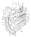
- the vehicle-side connector 20 includes a male housing 21 that is also made of synthetic resin.
- the male housing 21 has a terminal housing portion 22 that can be fitted into the small hood portion 13 of the female housing 12 and a front end side of the terminal housing portion 22 so as to cover the periphery of the small hood portion 13. And a large hood portion 24 formed so as to be fitted therein.
- the terminal housing portion 22 of the male housing 21 is formed with seven cavities 25 in which the terminal housing cylinders 14 of the female housing 12 can be fitted from the front in a corresponding arrangement. ing.
- male connection terminals are housed in a form protruding from the back wall.
- a male power terminal 26A for AC is provided in the cavity 25A on both sides of the middle stage
- a male ground terminal 26B is provided in the central cavity 25A
- a male side power terminal is provided in both upper cavities 25B.
- Each signal terminal 26C is accommodated.
- Both lower cavities 25C may house a male power terminal for DC or may be vacant.
- a rectangular mounting plate 28 is formed so as to protrude, and the four corners of the mounting plate 28 have power feeding openings opened in the vehicle body.
- the male housing 21 is mounted in a form in which the fitting surface thereof faces the power supply port by being fixed to the mounting member disposed inside by screwing.
- the terminal housing portion 22 of the male housing 21 is connected to the small hood portion 13 of the female housing 12 as shown in FIG. 4.
- the small hood portion 13 of the female housing 12 enters the hood portion entry groove 29 formed between the terminal housing portion 22 and the large hood portion 24 in the male housing 21, and enters the terminal housing portion 22.
- the fitting is stopped, and this position becomes the normal fitting position.
- a power feeding path is configured between the power source and the battery mounted on the vehicle.
- the power supply path is provided with a power supply switch 30 (see FIG. 8) that switches the power supply path between a conduction state and a cutoff state.
- the corresponding male and female signal terminals (only the male-side signal terminal 26 ⁇ / b> C is shown in FIG. 3) serve as fitting detection terminals, and the connection portion between the fitting detection terminals serves as the fitting detection unit 31.
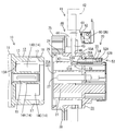
- An electromagnetic lock mechanism 40 that locks the housings 12 and 21 of the connectors 10 and 20 in a properly fitted state is provided.
- a locked hole 17 is opened at a position near the tip on the upper surface of the small hood portion 13.
- the vehicle-side connector 20 is provided with a solenoid actuator 41.
- the actuator 41 is provided with a locking pin 43 movably between a retracted position (FIG. 2) and a forward position (FIG. 4) with respect to the main body 42, and the locking pin 43 is always retracted by spring elasticity.
- the actuator 41 is energized and energized, the locking pin 43 is advanced to the forward position against the urging force.
- the locked hole 17 of the small hood portion 13 of the female housing 12 has a lower surface and a left and right side so that the actuator 41 can correspond to a case where the actuator 41 is disposed at a lower position and a left and right position in addition to the above-described upper position.
- the surface is also open.
- the male housing 21 of the vehicle-side connector 20 is engaged with the small hood 13 when the male and female housings 12 and 21 are properly fitted to each other, more specifically at a position near the rear end on the upper surface of the large hood 24.
- a guide hole 46 through which the locking pin 43 of the actuator 41 can be tightly inserted is opened at a position directly above the hole 17.
- an escape recess 47 for allowing the distal end portion of the locking pin 43 to escape is formed at a position directly below the guide hole 46 on the upper surface of the terminal accommodating portion 22, in other words, on the lower surface of the hood portion insertion groove 29.
- the guide hole 46 and the escape recess 47 are also provided on the lower surface and the left and right surfaces corresponding to the positions of the actuator 41 described above.
- the actuator 41 is attached to the vehicle-side connector 20 in a posture in which the front end of the locking pin 43 is inserted into the guide hole 46 and faces downward.
- a basic charge control system including a lock operation by the electromagnetic lock mechanism 40 will be described with reference to FIGS. 8 and 9 as follows.
- the actuator 41 is excited to be in the retracted position.
- the locking pin 43 has advanced to the forward position, the tip of the locking pin 43 passes through the locked hole 17 of the small hood portion 13 and reaches the recess 47, and the locking pin 43 is locked. 17, the connectors 10 and 20 are locked in the proper mating state, and then the power supply switch 30 is switched to the on state so that the power supply path is A conduction state is established and charging is performed.
- the power supply switch 30 When it is detected by the charging end detection unit 32 (FIG. 8) provided in the vehicle-side connector 20 that the predetermined charging has ended, the power supply switch 30 is switched to the OFF state, and the power supply path is interrupted. Subsequently, when an unlock command is issued from the unlock command section 33 (FIG. 8), the energization of the actuator 41 is cut off and the excitation is released, whereby the locking pin 43 returns to the retracted position and the lock is released. Then, the power supply side connector 10 can be removed.
- the release command signal from the lock release command unit 33 may be sent upon detection of the end of charging, or may be performed by operating an operation unit provided separately on the vehicle side.
- the electromagnetic lock mechanism 40 in view of the case where the electromagnetic lock mechanism 40 may not operate normally, it is displayed that there is a malfunction, and furthermore, when there is the malfunction, the power feeding operation is regulated.
- the following measures are taken. Basically, it has various detection units that detect the presence or absence of defects in the components of the electromagnetic lock mechanism 40, and the power supply control unit 71 (FIG. 8) performs arithmetic processing on the signal from the detection unit, Various members are controlled.
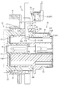
- a first detection switch 51 (locking portion detection unit) is provided as means for detecting a case where the locking pin 43 of the actuator 41 is defective.
- the first detection switch 51 is a normally open switch having a pair of movable contact 51A and fixed contact 51B, and is in an escape recess 47 provided on the bottom surface of the hood portion insertion groove 29 in the male housing 21 described above. Further, the movable contact 51A is arranged on the upper side.
- the tip of the locking pin 43 pushes the movable contact 51A to contact the fixed contact 51B, thereby turning on the first detection switch 51.
- the locking pin 43 cannot advance to the normal position for some reason, or when the tip of the locking pin 43 is missing, the locking pin 43 has advanced, The tip of the locking pin 43 cannot press the movable contact 51A, and the first detection switch 51 is kept in the off state.
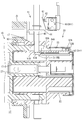
- a second detection switch 52 (locked portion detecting portion) is provided as means for detecting a case where there is a problem that the locked portion 18 constituting one of the electromagnetic lock mechanisms 40 is missing.
- the second detection switch 52 is a normally open switch having a pair of movable contacts 52A and a fixed contact 52B. About the arrangement position of the 2nd detection switch 52, as shown also in FIG.
- an operation detection unit that detects an advance / retreat operation of the locking pin 43 of the actuator 41 is provided.
- the micro switch 60 is disposed on the side of the advance / retreat path of the locking pin 43 in the actuator 41, and the operation lever 61 of the micro switch 60 is disposed on the outer periphery of the proximal end portion of the locking pin 43.
- An engageable flange 44 is formed.
- the micro switch 60 is, for example, a normally open type, and when the locking pin 43 is in the retracted position, as shown in FIG. Turn on. On the other hand, as shown in FIG. 4, when the locking pin 43 advances by a predetermined amount or more, the flange 44 is separated, the pressing force against the operating lever 61 is removed, and the button 62 returns, so that the micro switch 60 is turned off. Become.
- the micro switch 60 that is the operation detection unit described above, the first detection switch 51 that is the locking unit detection unit, and the second detection switch 52 that is the locked unit detection unit, It is connected to the input side of the charge control device 70.
- the charging control device 70 when the electromagnetic locking mechanism 40 does not operate properly, specifically, when the locking pin 43 of the actuator 41 has a problem and when the locked portion 18 is missing.
- a power supply control unit 71 including a lock error determination unit 72 is constructed.
- the power supply control unit 71 a program as shown in FIG. 10 is executed.
- the actuator 41 is excited, and then the power supply path is turned on only after both the detection parts are turned on.
- An error signal is output when one of the detection units is in an off state, and the error signal is received and displayed on the display unit 75.
- the display unit 75 has a display lamp made of a light emitting diode, and is provided at an upper position of the mounting plate 28 in the male housing 21 of the vehicle-side connector 20 as shown in FIG. It is arranged.
- an actuator error determination unit 73 is constructed in the charge control device 70 in response to the case where the locking pin 43 of the actuator 41 does not return to the retracted position. .
- the unlock command unit 33 is connected to the input side of the charge control device 70 as described above.
- the lock release command unit 33 is linked to the charge end detection unit 32 and outputs a lock release command signal when the charge end is detected.
- the lock release command unit 33 may issue a lock release command signal by operating a lock release operation unit separately provided on the vehicle side.
- the actuator error discriminating unit 73 executes a program as shown in FIG. That is, when it is detected that charging has been completed, the power supply path is interrupted, and then when the unlock command is received, the excitation of the actuator is released, but at that time the locking pin 43 has returned to the retracted position. If no error is detected, an error signal is output, and the error signal is received and displayed on the display unit 75. In addition, in the display part 75, you may make it light a display lamp different from the above-mentioned display lamp.
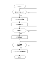
- step S10 when the power supply side connector 10 is fitted to the vehicle side connector 20 and is normally fitted as shown in FIG.
- step S10 When 31 is turned on (“YES” in step S10), the actuator 41 is energized and excited (step S11), so that the locking pin 43 passes through the locked hole 17 of the male housing 21. Advance. Subsequently, in step S12, it is determined whether or not the first detection switch 51 is on. If it is on (step S12 is “YES”), the tip of the locking pin 43 reaches the normal advance position, That is, it is considered that the locking pin 43 has normally passed through the locked hole 17, and the process proceeds to step S13.
- step S 13 it is determined whether or not the second detection switch 52 is on. If it is on (step S 13 is “YES”), the locked state that is the front edge of the locked hole 17 of the male housing 21. The portion 18 is present and is locked to the locking pin 43, that is, the electromagnetic lock mechanism 40 is properly operated and locked, and the power supply switch 30 is switched to the conductive state in step S14 and charging is performed. Be started.
- step S12 when there is a malfunction in the electromagnetic lock mechanism 40, for example, as shown by an arrow A in FIG. 5, the locking pin 43 of the actuator 41 is moving forward for some reason.
- the locking pin 43 does not push the movable contact 51A of the first detection switch 51 and remains off (step S12).
- Is “NO”) in step S15, it is considered that a lock error has occurred, and an error signal is transmitted.
- the display lamp of the display unit 75 is turned on, and it is informed that the electromagnetic lock mechanism 40 has a problem.
- the power supply switch 30 is kept off and charging is not performed.
- step S12 it is considered that there is a lock error, an error signal is sent, and the display unit 75 is turned on. The lamp lights up. Similarly, charging is not performed.
- step S12 when the locked portion 18 constituting one of the electromagnetic lock mechanisms 40 is damaged and missing, the locking pin 43 advances to the normal position and is Even if the first detection switch 51 is turned on ("YES" in step S12), the movable contact 52A of the second detection switch 52 is not pressed and the second detection switch 52 remains off (step S13 indicates " NO "), an error signal is sent out in step S15 because there is a lock error, the display lamp of the display unit 75 is turned on in response to this error signal, and it is notified that the electromagnetic lock mechanism 40 has a problem. . On the other hand, the power supply switch 30 is kept off and charging is not performed.
- step S20 At normal times, when it is detected that charging has ended ("YES” in step S20), the power supply switch 30 is turned off in step S21, the power supply path is shut off, and then a lock release command is issued (step S21).
- S22 is “YES”)
- step S23 the actuator 41 is de-energized, the excitation is released, the locking pin 43 is retracted as shown by the arrow B in FIG. 5, and the engaging pin 43 is engaged as shown in FIG.
- the program is terminated.
- Step S24 it is considered that there is an actuator error, and an error signal is transmitted.
- the display lamp of the display unit 75 is turned on to inform that the locking pin 43 of the actuator 41 has not returned to the normal retracted position, that is, the lock has not been completely released. If the vehicle-side connector 20 is forcibly removed in such a state, the electromagnetic lock mechanism 40 may be damaged. Therefore, the user or the like waits for the operation of pulling out the vehicle-side connector 20, and at the same time, the actuator 41 It will be a place to call for repairs.
- the following effects can be obtained.
- the locking pin 43 is retracted with the actuator 41 de-energized in order to release the lock, if the locking pin 43 does not return to the retracted position normally, the locking pin 43 is not connected to the mating power supply side connector 10. There is a possibility that the locking pin 17 remains penetrated or the tip of the locking pin 43 remains in the locked hole 17. If the power supply connector 10 is forcibly removed in this state, There is a possibility that an excessive load is applied to the locking pin 43 or the locked portion 18 and the actuator 41 itself is damaged.
- the disk-shaped flange is exemplified as the pressing portion provided on the latch pin of the actuator so as to be able to engage with the microswitch.
- the pressing plate is not limited to this and protrudes toward the microswitch side. It may be of other shapes such as.
- the latching portion of the actuator is not limited to the pin shape like the latching pin exemplified in the above embodiment, but may have other shapes as long as it can be advanced and retracted such as a plate shape and a single shape.
- the to-be-latched part provided in a power supply side connector may be other shapes, such as a protrusion, as long as it can latch to the latching
- the operation detection unit for detecting whether or not the latching portion of the actuator is in the retracted position is not limited to the micro switch exemplified in the above embodiment, and other types of switches such as limit switches are applied. Also good.
- a lighting display means for turning on the lamp was adopted, but instead, a warning sound generating means such as a buzzer was used, You may make it use both means together.
- the charge control system illustrated in the above embodiment is merely an example, and can be changed as appropriate.
- the charging end detection unit may detect the charging end in addition to the full charging of the battery, such as time-up of a preset charging time, manual operation of a charging end switch, or the like.
- the vehicle side connector is exemplified as one that can be used for both normal charging and quick charging, but the vehicle side connector corresponding to only one of normal charging and quick charging is equipped. The present invention can be applied in the same way.
Landscapes
- Engineering & Computer Science (AREA)
- Power Engineering (AREA)
- Transportation (AREA)
- Mechanical Engineering (AREA)
- Life Sciences & Earth Sciences (AREA)
- Sustainable Development (AREA)
- Sustainable Energy (AREA)
- Details Of Connecting Devices For Male And Female Coupling (AREA)
- Electric Propulsion And Braking For Vehicles (AREA)
- Charge And Discharge Circuits For Batteries Or The Like (AREA)
Abstract
Description
ところで上記従来の電磁ロック機構において、ロックを解除するべくアクチュエータが非励磁とされて係止部が後退する場合に、何らかの原因により係止部が正規の後退位置まで戻り切らないことがないとは言えない。このときは未だロックが掛かったままであったり、半ロック状態にある可能性が高いため、このような事態を看過したまま電源側コネクタを取り外すと、係止部と被係止部等に過大な負荷が作用して損傷を招くおそれがあった。
本発明は上記のような事情に基づいて完成されたものであって、その目的は、電磁ロック機構を構成するアクチュエータの係止部の後退動作に異常があった場合に警告できるようにするところにある。
本発明は、外部電源に接続された電源側コネクタと、車両に搭載されたバッテリと接続され前記電源側コネクタと嵌合されることで給電路を構成するべく車両に設けられた車両側コネクタと、前記給電路の接続と遮断とを切り換える給電スイッチと、前記車両側コネクタに設けられ前記電源側コネクタの被係止部に係止する係止部を進退駆動可能に備えたソレノイド式のアクチュエータと、が具備され、前記両コネクタが嵌合されると、前記アクチュエータの前記係止部が進出して前記被係止部に係止することにより前記両コネクタを嵌合状態にロックし、続いて前記給電スイッチの切り換えにより前記給電路を接続し、充電が終了すると、前記給電スイッチの切り換えにより前記給電路を遮断し、続いて前記アクチュエータの前記係止部を後退させることによりロックを解除するようにした車両用充電装置において、前記アクチュエータの前記係止部が後退位置にあるか否かを検知する動作検知部と、前記アクチュエータの前記係止部が後退駆動されたにも拘わらず前記動作検知部が前記係止部が後退位置まで戻ったことを検知できなかった場合に、エラーがあったと判別してエラー信号を送出するエラー判別部と、前記エラー信号を受けて警告する警告部と、が設けられているところに特徴を有する。
(1)前記電源側コネクタのハウジングには、前記車両側コネクタのハウジングが内側に嵌合可能なフード部が設けられ、同フード部に被係止孔が開口されることで前記被係止部が構成されているとともに、前記車両側コネクタの前記ハウジングには、前記被係止孔を貫通して進退可能な係止ピンを備えたアクチュエータが設けられて、前記係止ピンが前記係止部を構成している。
アクチュエータの係止ピンが正規に後退位置まで戻っていないと、係止ピンが被係止孔を貫通したままであったり、係止ピンの先端が被係止孔内に留まっている可能性があり、この状態で電源側コネクタを無理に外そうとすると、係止ピンや被係止部に過大な負荷が掛かって損傷したり、アクチュエータ自体が損傷するおそれがあるが、警告を受けて電源側コネクタの取り外しを控えることにより、上記のような損傷が未然に防止される。
アクチュエータの係止ピンが後退駆動して正規に後退位置まで戻ると、押圧部がマイクロスイッチを押圧して開閉状態が切り換えられることにより戻ったことが検知され、逆にマイクロスイッチが押圧されないで開閉状態が切り換わらないことによって、係止ピンが正規の後端位置まで戻らなかったと見なされる。
本発明によれば、電磁ロック機構を構成するアクチュエータの係止部の後退動作に異常があった場合にこれを検知して警告することができる。
本発明の一実施形態を図1ないし図11に基づいて説明する。
本実施形態の車両用充電装置は、図1及び図2に示すように、電源と接続される電源側コネクタ10と、車両に搭載されたバッテリと接続されて同車両に設けられた車両側コネクタ20とから構成されている。
一方、2組の雌雄の信号端子同士が接続されると、2本の信号線が構成され、本実施形態では、そのうちの1本が両コネクタ10,20の嵌合検知用に利用されている。そのため、対応する雌雄の信号端子(雄側の信号端子26Cのみが図3に図示)が嵌合検知端子となり、同嵌合検知端子同士の接続部分が嵌合検知部31となる。
図2に示すように、電源側コネクタ10に設けられた雌ハウジング12側では、小フード部13の上面における先端部寄りの位置に被係止孔17が開口されている。
一方、車両側コネクタ20には、ソレノイド式のアクチュエータ41が設けられている。このアクチュエータ41は、本体42に対して係止ピン43が後退位置(図2)と前進位置(図4)との間で移動可能に設けられ、常にはばね弾力により係止ピン43が後退位置に後退付勢され、同アクチュエータ41に通電して励磁すると、係止ピン43が付勢力に抗して前進位置に進出するようになっている。
なお、雌ハウジング12の小フード部13の被係止孔17は、アクチュエータ41が上記した上方位置以外に、下方位置並びに左右の位置に配された場合にも対応できるように、下面並びに左右の面にも開口されている。
そしてアクチュエータ41は、係止ピン43の先端をガイド孔46内に挿入した形態で真下を向いた姿勢において、車両側コネクタ20に対して装着されている。
両コネクタ10,20が正規に嵌合されたことが、嵌合検知部31を構成する一対の信号端子が接続されることで検知されると、アクチュエータ41が励磁されることにより後退位置にあった係止ピン43が前進位置に進出し、同係止ピン43の先端が小フード部13の被係止孔17を貫通して逃がし凹部47にまで達し、係止ピン43が被係止孔17における前側の縁部(被係止部18)に係止することで、両コネクタ10,20が正規の嵌合状態にロックされ、続いて給電スイッチ30がオン状態に切り換えられて給電路が導通状態とされ、充電が行われる。
基本的には、電磁ロック機構40の構成部品の不具合の有無を検知する各種検知部を備え、その検知部からの信号等を給電制御部71(図8)によって演算処理し、その演算結果により各種部材を制御するようになっている。
一方、例えば係止ピン43が何らかの事情で正規位置まで進出できなかった場合、あるいは係止ピン43の先端部が欠損しているような場合は、係止ピン43が進出したにも拘わらず、係止ピン43の先端が可動接点51Aを押圧できず、第1検知スイッチ51がオフ状態に留められる。
第2検知スイッチ52の配設位置については、図3にも示すように、雄ハウジング21の端子収容部22の上面におけるフード部挿入溝29の奥壁29Aよりも後方領域、より詳細には、第1検知スイッチ51の配設位置の後方に対応する領域には、前後方向に沿ったガイド路54が形成され、第2検知スイッチ52は、同ガイド路54の後端部において、可動接点52Aを手前側に配した形態で装着されている。
ガイド路54には、作動板55が前後方向へ摺動可能に載置されており、同作動板55の前面に突設された被押圧片55Aが、奥壁29Aに形成されたガイド孔54Aを貫通してフード部挿入溝29内に突出している。
一方、被係止部18が損傷を受けて欠落している場合は、例え両コネクタ10,20が正規嵌合されたとしても、被押圧片55Aすなわち作動板55を後方に押し込むことができず、すなわち可動接点52Aを押圧できず、第2検知スイッチ52がオフ状態に留められる。
具体的には、アクチュエータ41における係止ピン43の進退路の側方にマイクロスイッチ60が配設される一方、係止ピン43の基端部の外周には、マイクロスイッチ60の作動レバー61と係合可能なフランジ44が形成されている。
充電制御装置70には、電磁ロック機構40が正規に作動しない場合、具体的には、アクチュエータ41の係止ピン43に不具合があった場合と、被係止部18が欠落した不具合があった場合の両方に対応するために、ロックエラー判別部72を含む給電制御部71が構築されている。
この表示部75は、発光ダイオードからなる表示ランプを有しており、図1に示すように、車両側コネクタ20の雄ハウジング21における取付板28の上部位置に設けられ、給電口を通して目視可能に配されている。
そのため、充電制御装置70の入力側には、一部既述したようにロック解除指令部33が接続されている。ロック解除指令部33は、充電終了検知部32と連動しており、充電終了が検知されたことに伴いロック解除指令信号を出すようになっている。なお、同ロック解除指令部33は、車両側に別途備えたロック解除操作部の操作によりロック解除指令信号を出すようにしてもよい。
まず、図10のフローチャートを参照し、電源側コネクタ10を車両側コネクタ20に嵌合して、図4に示すように正規嵌合されると、一対の信号端子が接続されて嵌合検知部31がオンとなることで(ステップS10が「YES」)、アクチュエータ41に通電されて励磁され(ステップS11)、これにより係止ピン43が、雄ハウジング21の被係止孔17に貫通するべく進出する。続いて、ステップS12において、第1検知スイッチ51がオンであるか否かが判別され、オンであったら(ステップS12が「YES」)、係止ピン43の先端が正規の進出位置に達し、すなわち係止ピン43が被係止孔17を正規に貫通したと見なされてステップS13に移る。ステップS13では、第2検知スイッチ52がオンであるか否かが判別され、オンであったら(ステップS13が「YES」)、雄ハウジング21の被係止孔17の前縁である被係止部18が存在して係止ピン43に係止しており、すなわち電磁ロック機構40が正規に作動してロックが掛かったと見なされ、ステップS14で給電スイッチ30が導通状態に切り換えられて充電が開始される。
このような状態で車両側コネクタ20を無理に外そうとすると、電磁ロック機構40に損傷を与えるおそれがあるため、ユーザー等には車両側コネクタ20の引き抜き操作を待機させ、併せてアクチュエータ41の修理等を喚起するところとなる。
それを受けてユーザー等が電源側コネクタ10の引き抜き操作を控えることによって、電磁ロック機構40が損傷を受けることが未然に防止され、また、アクチュエータ41の修理等に迅速に対応することが可能となる。
本発明は上記記述及び図面によって説明した実施形態に限定されるものではなく、例えば次のような実施形態も本発明の技術的範囲に含まれる。
(1)アクチュエータの係止ピンにマイクロスイッチと係合可能に設けられた押圧部として、上記実施形態では円盤状のフランジを例示したが、それに限らず、マイクロスイッチ側に向けて突出した押圧板等のような他の形状のものであってもよい。
(2)アクチュエータの係止部は、上記実施形態に例示した係止ピンのようなピン形状に限らず、板形状、片形状等の進退駆動できる限り他の形状のものであってもよい。また、電源側コネクタに設ける被係止部は、アクチュエータの係止部に係止し得る限り、突部等の他の形状であってもよい。
(4)上記実施形態では、アクチュエータにエラーがあったことを警告する手段として、ランプを点灯する点灯表示手段を採用したが、それに代わってブザーを鳴らす等の警告音発生手段を採用したり、両手段を併用するようにしてもよい。
(6)上記実施形態では、車両側コネクタとして普通充電と急速充電とに兼用して対応し得るものを例示したが、普通充電と急速充電のいずれか一方のみに対応する車両側コネクタが装備されている場合についても、本発明は同様に適用することができる。
12…雌ハウジング(電源側コネクタのハウジング)
13…小フード部(フード部)
17…被係止孔
18…被係止部
20…車両側コネクタ
21…雄ハウジング(車両側コネクタのハウジング)
30…給電スイッチ
31…嵌合検知部
40…電磁ロック機構
41…アクチュエータ
43…係止ピン(係止部)
44…フランジ(押圧部)
60…マイクロスイッチ(動作検知部)
70…充電制御装置
71…給電制御部
73…アクチュエータエラー判別部(エラー判別部)
75…表示部(警告部)
Claims (3)
- 外部電源に接続された電源側コネクタと、
車両に搭載されたバッテリと接続され前記電源側コネクタと嵌合されることで給電路を構成するべく車両に設けられた車両側コネクタと、
前記給電路の接続と遮断とを切り換える給電スイッチと、
前記車両側コネクタに設けられ前記電源側コネクタの被係止部に係止する係止部を進退駆動可能に備えたソレノイド式のアクチュエータと、
が具備され、
前記両コネクタが嵌合されると、前記アクチュエータの前記係止部が進出して前記被係止部に係止することにより前記両コネクタを嵌合状態にロックし、続いて前記給電スイッチの切り換えにより前記給電路を接続し、充電が終了すると、前記給電スイッチの切り換えにより前記給電路を遮断し、続いて前記アクチュエータの前記係止部を後退させることによりロックを解除するようにした車両用充電装置において、
前記アクチュエータの前記係止部が後退位置にあるか否かを検知する動作検知部と、
前記アクチュエータの前記係止部が後退駆動されたにも拘わらず、前記動作検知部によって前記係止部が後退位置まで戻ったことを検知できなかった場合に、エラーがあったと判別してエラー信号を送出するエラー判別部と、
前記エラー信号を受けて警告する警告部と、
が設けられていることを特徴とする車両用充電装置。 - 前記電源側コネクタのハウジングには、前記車両側コネクタのハウジングが内側に嵌合可能なフード部が設けられ、同フード部に被係止孔が開口されることで前記被係止部が構成されているとともに、
前記車両側コネクタの前記ハウジングには、前記被係止孔を貫通して進退可能な係止ピンを備えたアクチュエータが設けられて、前記係止ピンが前記係止部を構成していることを特徴とする請求項1記載の車両用充電装置。 - 前記動作検知部は、前記アクチュエータにおける前記係止ピンの基端側に設けられた押圧部で押圧されることにより開閉状態が反転するマイクロスイッチにより構成されていることを特徴とする請求項2記載の車両用充電装置。
Priority Applications (5)
| Application Number | Priority Date | Filing Date | Title |
|---|---|---|---|
| EP11874517.3A EP2705974A1 (en) | 2011-10-25 | 2011-10-25 | Vehicle charging device |
| CN201180072473.7A CN103687748A (zh) | 2011-10-25 | 2011-10-25 | 车辆用充电装置 |
| JP2013540526A JP5610086B2 (ja) | 2011-10-25 | 2011-10-25 | 車両用充電装置 |
| PCT/JP2011/074486 WO2013061400A1 (ja) | 2011-10-25 | 2011-10-25 | 車両用充電装置 |
| US14/353,920 US20140292276A1 (en) | 2011-10-25 | 2011-10-25 | Vehicle charging device |
Applications Claiming Priority (1)
| Application Number | Priority Date | Filing Date | Title |
|---|---|---|---|
| PCT/JP2011/074486 WO2013061400A1 (ja) | 2011-10-25 | 2011-10-25 | 車両用充電装置 |
Publications (1)
| Publication Number | Publication Date |
|---|---|
| WO2013061400A1 true WO2013061400A1 (ja) | 2013-05-02 |
Family
ID=48167267
Family Applications (1)
| Application Number | Title | Priority Date | Filing Date |
|---|---|---|---|
| PCT/JP2011/074486 WO2013061400A1 (ja) | 2011-10-25 | 2011-10-25 | 車両用充電装置 |
Country Status (5)
| Country | Link |
|---|---|
| US (1) | US20140292276A1 (ja) |
| EP (1) | EP2705974A1 (ja) |
| JP (1) | JP5610086B2 (ja) |
| CN (1) | CN103687748A (ja) |
| WO (1) | WO2013061400A1 (ja) |
Cited By (4)
| Publication number | Priority date | Publication date | Assignee | Title |
|---|---|---|---|---|
| JP2014087198A (ja) * | 2012-10-25 | 2014-05-12 | Auto Network Gijutsu Kenkyusho:Kk | アンロック制御装置 |
| JP2017216870A (ja) * | 2016-05-31 | 2017-12-07 | ティーイー コネクティビティ ジャーマニー ゲゼルシャフト ミット ベシュレンクテル ハフツンクTE Connectivity Germany GmbH | 充電導入口用アクチュエータモジュール |
| JP2018037210A (ja) * | 2016-08-30 | 2018-03-08 | 株式会社豊田自動織機 | 電池パック及び充電口ユニット |
| CN109217025A (zh) * | 2017-07-06 | 2019-01-15 | 大众汽车有限公司 | 用于机动车的充电插座的锁止系统 |
Families Citing this family (24)
| Publication number | Priority date | Publication date | Assignee | Title |
|---|---|---|---|---|
| JP5798935B2 (ja) * | 2012-01-17 | 2015-10-21 | 矢崎総業株式会社 | 電気コネクタ |
| JP5939927B2 (ja) * | 2012-08-06 | 2016-06-22 | 矢崎総業株式会社 | 充電コネクタ |
| JP5981294B2 (ja) * | 2012-10-12 | 2016-08-31 | 矢崎総業株式会社 | 充電インレット装置 |
| FR3030135B1 (fr) * | 2014-12-11 | 2018-01-05 | Schneider Electric Industries Sas | Systeme de raccordement d'un circuit de puissance electrique et installation de charge d'un vehicule electrique comprenant un tel systeme de raccordement |
| JP6009528B2 (ja) * | 2014-12-18 | 2016-10-19 | 住友電装株式会社 | 充電用インレット |
| FR3048560B1 (fr) * | 2016-03-02 | 2019-07-05 | Aldebaran Robotics | Ensemble de rechargement d'une batterie et procede de recharge mettant en oeuvre un tel ensemble |
| CN106945561B (zh) * | 2017-04-20 | 2018-07-31 | 江苏锡沂高新区科技发展有限公司 | 一种能自动控制的新能源汽车充电装置 |
| WO2018192624A1 (de) * | 2017-04-21 | 2018-10-25 | Harting Electric Gmbh & Co. Kg | Anbaugehäuseanordnung und verfahren zur entriegelung |
| KR102322857B1 (ko) * | 2017-04-28 | 2021-11-08 | 현대자동차주식회사 | 충전 커넥터 잠금 시스템에서의 고장 판단 방법 |
| CN106992371A (zh) * | 2017-05-28 | 2017-07-28 | 詹胜超 | 一种手机构件 |
| US10868389B2 (en) * | 2017-08-21 | 2020-12-15 | Hubbell Incorporated | Electrical contact device with interlock |
| CN107394520B (zh) * | 2017-09-05 | 2023-05-05 | 东台正耀精密技术有限公司 | 电连接器组合 |
| CN107776428B (zh) * | 2017-10-24 | 2018-07-20 | 河南凯德伦精密工业制造有限公司 | 一种新能源汽车充电设备 |
| CN108790899B (zh) * | 2018-06-24 | 2020-08-21 | 湖南京能新能源科技有限公司 | 直流通电新能源汽车充电桩的自锁紧方法 |
| US11531787B2 (en) | 2019-07-29 | 2022-12-20 | International Business Machines Corporation | Management of securable computing resources |
| US10916889B1 (en) * | 2019-07-29 | 2021-02-09 | International Business Machines Corporation | Management of securable computing resources |
| US11341278B2 (en) | 2019-07-29 | 2022-05-24 | International Business Machines Corporation | Management of securable computing resources |
| US11669602B2 (en) | 2019-07-29 | 2023-06-06 | International Business Machines Corporation | Management of securable computing resources |
| US11210427B2 (en) | 2019-07-29 | 2021-12-28 | International Business Machines Corporation | Management of securable computing resources |
| US11341279B2 (en) | 2019-07-29 | 2022-05-24 | International Business Machines Corporation | Management of securable computing resources |
| US11370315B2 (en) * | 2020-08-25 | 2022-06-28 | Ford Global Technologies, Llc | Hands-free charging system with internal power source |
| CN113895256A (zh) * | 2021-10-09 | 2022-01-07 | 深圳市中蓝绿源科技有限公司 | 一种智能充电枪头 |
| DE102022208502B4 (de) * | 2022-08-16 | 2024-04-04 | Franz Binder GmbH & Co Elektrische Bauelemente Kommanditgesellschaft | Elektrischer Steckverbinder und Steckverbindersystem |
| CN117984825A (zh) * | 2024-04-03 | 2024-05-07 | 福建省加成信息技术有限公司 | 一种移动式充电装置及其充电方法 |
Citations (6)
| Publication number | Priority date | Publication date | Assignee | Title |
|---|---|---|---|---|
| JPH04312775A (ja) * | 1991-04-10 | 1992-11-04 | Nec Corp | コネクタ |
| JPH0878095A (ja) * | 1994-09-08 | 1996-03-22 | Yazaki Corp | 電気コネクタのアース接続方法およびアース接続構造 |
| JPH08130062A (ja) * | 1994-10-27 | 1996-05-21 | Sumitomo Wiring Syst Ltd | 嵌合検知機能付きコネクタ |
| JP2010004731A (ja) * | 2008-05-19 | 2010-01-07 | Fuji Heavy Ind Ltd | 電気自動車の制御装置 |
| JP2011081952A (ja) | 2009-10-05 | 2011-04-21 | Toyota Motor Corp | コネクタのロック機構 |
| JP2011165558A (ja) * | 2010-02-12 | 2011-08-25 | Tokai Rika Co Ltd | バッテリ充電用受電コネクタのコネクタロック構造 |
Family Cites Families (6)
| Publication number | Priority date | Publication date | Assignee | Title |
|---|---|---|---|---|
| JP2752032B2 (ja) * | 1993-09-20 | 1998-05-18 | 矢崎総業株式会社 | 給電コネクタ |
| JPH07272794A (ja) * | 1994-03-31 | 1995-10-20 | Mitsubishi Electric Corp | コネクタ装置 |
| JP2012080646A (ja) * | 2010-09-30 | 2012-04-19 | Tokai Rika Co Ltd | 給電プラグロック装置 |
| JP5572655B2 (ja) * | 2012-03-19 | 2014-08-13 | 本田技研工業株式会社 | 燃料電池車両の外部給電制御装置 |
| JP5916476B2 (ja) * | 2012-03-29 | 2016-05-11 | 古河電気工業株式会社 | 給電コネクタ |
| CN104737380A (zh) * | 2012-10-31 | 2015-06-24 | 古河电气工业株式会社 | 供电连接器及供电连接器的锁定解除方法 |
-
2011
- 2011-10-25 CN CN201180072473.7A patent/CN103687748A/zh active Pending
- 2011-10-25 WO PCT/JP2011/074486 patent/WO2013061400A1/ja active Application Filing
- 2011-10-25 EP EP11874517.3A patent/EP2705974A1/en not_active Withdrawn
- 2011-10-25 US US14/353,920 patent/US20140292276A1/en not_active Abandoned
- 2011-10-25 JP JP2013540526A patent/JP5610086B2/ja not_active Expired - Fee Related
Patent Citations (6)
| Publication number | Priority date | Publication date | Assignee | Title |
|---|---|---|---|---|
| JPH04312775A (ja) * | 1991-04-10 | 1992-11-04 | Nec Corp | コネクタ |
| JPH0878095A (ja) * | 1994-09-08 | 1996-03-22 | Yazaki Corp | 電気コネクタのアース接続方法およびアース接続構造 |
| JPH08130062A (ja) * | 1994-10-27 | 1996-05-21 | Sumitomo Wiring Syst Ltd | 嵌合検知機能付きコネクタ |
| JP2010004731A (ja) * | 2008-05-19 | 2010-01-07 | Fuji Heavy Ind Ltd | 電気自動車の制御装置 |
| JP2011081952A (ja) | 2009-10-05 | 2011-04-21 | Toyota Motor Corp | コネクタのロック機構 |
| JP2011165558A (ja) * | 2010-02-12 | 2011-08-25 | Tokai Rika Co Ltd | バッテリ充電用受電コネクタのコネクタロック構造 |
Cited By (6)
| Publication number | Priority date | Publication date | Assignee | Title |
|---|---|---|---|---|
| JP2014087198A (ja) * | 2012-10-25 | 2014-05-12 | Auto Network Gijutsu Kenkyusho:Kk | アンロック制御装置 |
| JP2017216870A (ja) * | 2016-05-31 | 2017-12-07 | ティーイー コネクティビティ ジャーマニー ゲゼルシャフト ミット ベシュレンクテル ハフツンクTE Connectivity Germany GmbH | 充電導入口用アクチュエータモジュール |
| JP7085312B2 (ja) | 2016-05-31 | 2022-06-16 | ティーイー コネクティビティ ジャーマニー ゲゼルシャフト ミット ベシュレンクテル ハフツンク | 充電導入口用アクチュエータモジュール |
| JP2018037210A (ja) * | 2016-08-30 | 2018-03-08 | 株式会社豊田自動織機 | 電池パック及び充電口ユニット |
| CN109217025A (zh) * | 2017-07-06 | 2019-01-15 | 大众汽车有限公司 | 用于机动车的充电插座的锁止系统 |
| CN109217025B (zh) * | 2017-07-06 | 2021-03-12 | 大众汽车有限公司 | 用于机动车的充电插座的锁止系统 |
Also Published As
| Publication number | Publication date |
|---|---|
| JPWO2013061400A1 (ja) | 2015-04-02 |
| CN103687748A (zh) | 2014-03-26 |
| US20140292276A1 (en) | 2014-10-02 |
| EP2705974A1 (en) | 2014-03-12 |
| JP5610086B2 (ja) | 2014-10-22 |
Similar Documents
| Publication | Publication Date | Title |
|---|---|---|
| JP5610086B2 (ja) | 車両用充電装置 | |
| JP5610088B2 (ja) | 車両用充電装置 | |
| JP5610087B2 (ja) | 車両用充電装置 | |
| CN107069323B (zh) | 连接器 | |
| JP5972391B2 (ja) | 給電コネクタおよび給電コネクタのロック解除方法 | |
| JP5182941B2 (ja) | 複合コネクタ | |
| JP5798935B2 (ja) | 電気コネクタ | |
| KR101484815B1 (ko) | 커넥터 유지 장치 및 그것을 구비한 충전 장치 | |
| JP5715879B2 (ja) | アーク放電防止コネクタ | |
| WO2014157196A1 (ja) | 充電コネクタ | |
| RU2578127C2 (ru) | Блок вспомогательных контактов | |
| JP5889432B2 (ja) | 給電コネクタ | |
| JP5815425B2 (ja) | 電気コネクタ | |
| JP6050680B2 (ja) | コネクタ | |
| JP2013149385A (ja) | 電気コネクタ | |
| JP2014150012A (ja) | コネクタ | |
| KR102259191B1 (ko) | 부착 하우징 장치 및 잠금 해제 방법 | |
| JP5815423B2 (ja) | 電気コネクタ | |
| JP5273071B2 (ja) | 充電プラグ | |
| JP5697053B2 (ja) | 給電コネクタ | |
| JP2015072855A (ja) | 車両用外部充電器接続構造 | |
| JP2014051239A (ja) | 回路導通遮断装置 | |
| JP5825523B2 (ja) | コネクタ装置 | |
| JP2014230342A (ja) | 車両用外部充電器接続構造の故障検出装置およびこれを用いた車両用充電装置 |
Legal Events
| Date | Code | Title | Description |
|---|---|---|---|
| 121 | Ep: the epo has been informed by wipo that ep was designated in this application |
Ref document number: 11874517 Country of ref document: EP Kind code of ref document: A1 |
|
| ENP | Entry into the national phase |
Ref document number: 2013540526 Country of ref document: JP Kind code of ref document: A |
|
| WWE | Wipo information: entry into national phase |
Ref document number: 2011874517 Country of ref document: EP |
|
| WWE | Wipo information: entry into national phase |
Ref document number: 14353920 Country of ref document: US |
|
| NENP | Non-entry into the national phase |
Ref country code: DE |