WO2013061362A1 - 波動歯車装置を備えたアクチュエータの位置決め制御システム - Google Patents
波動歯車装置を備えたアクチュエータの位置決め制御システム Download PDFInfo
- Publication number
- WO2013061362A1 WO2013061362A1 PCT/JP2011/005951 JP2011005951W WO2013061362A1 WO 2013061362 A1 WO2013061362 A1 WO 2013061362A1 JP 2011005951 W JP2011005951 W JP 2011005951W WO 2013061362 A1 WO2013061362 A1 WO 2013061362A1
- Authority
- WO
- WIPO (PCT)
- Prior art keywords
- motor
- nonlinear
- load
- friction
- shaft
- Prior art date
- Legal status (The legal status is an assumption and is not a legal conclusion. Google has not performed a legal analysis and makes no representation as to the accuracy of the status listed.)
- Ceased
Links
Images





Classifications
-
- G—PHYSICS
- G05—CONTROLLING; REGULATING
- G05B—CONTROL OR REGULATING SYSTEMS IN GENERAL; FUNCTIONAL ELEMENTS OF SUCH SYSTEMS; MONITORING OR TESTING ARRANGEMENTS FOR SUCH SYSTEMS OR ELEMENTS
- G05B5/00—Anti-hunting arrangements
-
- H—ELECTRICITY
- H02—GENERATION; CONVERSION OR DISTRIBUTION OF ELECTRIC POWER
- H02P—CONTROL OR REGULATION OF ELECTRIC MOTORS, ELECTRIC GENERATORS OR DYNAMO-ELECTRIC CONVERTERS; CONTROLLING TRANSFORMERS, REACTORS OR CHOKE COILS
- H02P23/00—Arrangements or methods for the control of AC motors characterised by a control method other than vector control
-
- F—MECHANICAL ENGINEERING; LIGHTING; HEATING; WEAPONS; BLASTING
- F16—ENGINEERING ELEMENTS AND UNITS; GENERAL MEASURES FOR PRODUCING AND MAINTAINING EFFECTIVE FUNCTIONING OF MACHINES OR INSTALLATIONS; THERMAL INSULATION IN GENERAL
- F16H—GEARING
- F16H49/00—Other gearings
- F16H49/001—Wave gearings, e.g. harmonic drive transmissions
-
- G—PHYSICS
- G05—CONTROLLING; REGULATING
- G05B—CONTROL OR REGULATING SYSTEMS IN GENERAL; FUNCTIONAL ELEMENTS OF SUCH SYSTEMS; MONITORING OR TESTING ARRANGEMENTS FOR SUCH SYSTEMS OR ELEMENTS
- G05B2219/00—Program-control systems
- G05B2219/30—Nc systems
- G05B2219/49—Nc machine tool, till multiple
- G05B2219/49292—Harmonic gear, transmission, strain wave gear
Definitions
- the present invention relates to an actuator positioning control system that decelerates the rotation output of a motor via a wave gear device and outputs the reduced output from a load shaft. More specifically, a wave gear device that can suppress a decrease in load shaft positioning control accuracy caused by nonlinear spring characteristics, relative rotational synchronization components, and nonlinear friction of the wave gear device using a strict linearization method.
- the present invention relates to an actuator positioning control system.
- an actuator using a wave gear device as a speed reducer for decelerating and outputting the rotation of a motor is known.
- a controller for positioning control of the actuator having this configuration a semi-conductor that detects the rotational position and rotational speed of the motor shaft by an encoder attached to the motor shaft and controls the rotation of the load shaft that is the output shaft of the speed reducer based on this. Closed loop control systems are known. In the semi-closed loop control system, since the rotation information of the load shaft is directly detected and the motor is not driven and controlled, the characteristics of the wave gear device greatly affect the positioning control characteristics of the load shaft.
- the wave gear device has non-linear spring characteristics and non-linear friction with hysteresis due to a unique structure utilizing elastic deformation of the gear.
- vibrations and angular transmission errors generated in synchronization with rotation due to gear machining errors and assembly errors generate steady deviations and vibrations, particularly at the load position of the semi-closed loop control system. Therefore, in order to realize high-accuracy control of the load shaft, a control system that can uniformly compensate for such nonlinear characteristics is required.
- FIG. 6 shows a block diagram of the strict linearization method.
- This is a technique for linearizing the control object without using approximation (Non-Patent Document 1).
- An object of the present invention is to provide an actuator equipped with a wave gear device in which compensation based on a strict linearization method for nonlinear characteristics of the wave gear device is extended not only to nonlinear spring properties but also to angle transmission error components and nonlinear friction. It is to propose a positioning control system.
- the present invention is a positioning system that performs drive control of an actuator that decelerates rotation of a motor via a wave gear device and transmits it to a load shaft, and performs positioning control of the load shaft.
- feedforward for compensating positioning errors of the load axis and semi-closed loop type feedback controller for controlling positioning of the load shaft by feeding back the motor shaft position theta m, due to the nonlinear element of the actuator A type linearization compensator is included.
- the non-linear element to be compensated includes only the relative rotational synchronization component, the non-linear friction only, the relative rotational synchronous component and the non-linear spring characteristic, the non-linear friction and the non-linear spring characteristic, the relative rotational synchronous component and the non-linear characteristic. In some cases, it includes friction, and may include nonlinear spring characteristics, the relative rotational synchronization component, and the nonlinear friction.
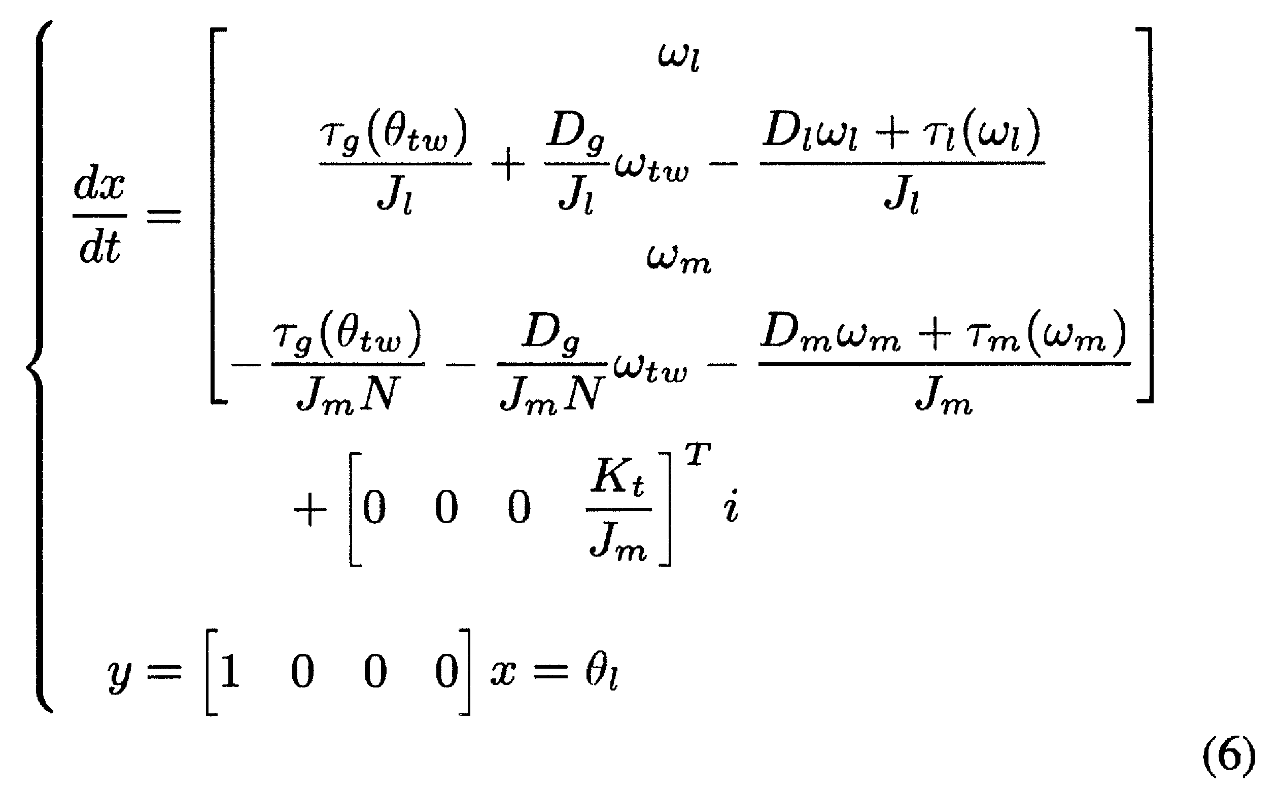
- the feedforward linearization compensator incorporates a nonlinear plant model representing the actuator to be controlled into a feedback linearization compensator based on a strict linearization method, thereby providing the feedback linearization compensator. This is equivalent to the feed forward type.
- the feedback type linearization compensator adds the linearization feedback ⁇ (x) and the input variable ⁇ (x) with the state quantity x as arguments to the nonlinear plant model.
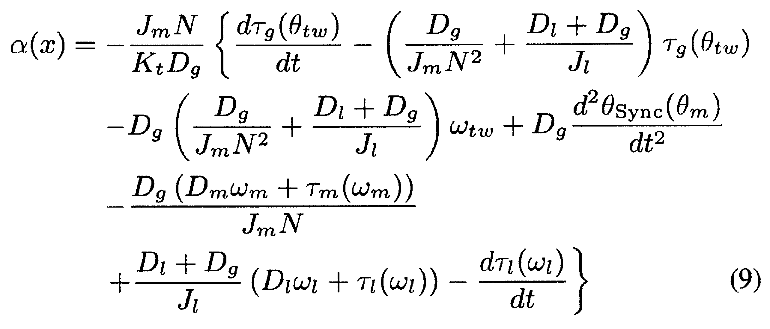
- the linearization feedback ⁇ (x) is defined by equation (9)
- the input variable ⁇ (x) is (10 ) Formula.
- the feedforward linearization compensator uses a state acceleration value x * calculated based on the nonlinear plant model with a load jerk command (jerk command) j ref as the input ⁇ , and the output y A certain feedforward current command i * ref is calculated, and a feedforward motor position command ⁇ * m that is input to the feedback controller is calculated.
- the non-linear spring characteristic in the present invention is a non-linear spring characteristic with respect to a load torque of the wave gear device defined by the equation (1), and a load torque is applied to the actuator to twist between the load torque and the motor / load shaft.
- the coefficients K g1 , K g2 , and K g3 of each order in the equation (1) are set so that the actual machine nonlinear spring characteristics obtained by measuring the angle relationship can be reproduced.
- the relative rotation synchronization component in the present invention is defined by the equation (3), with the motor shaft synchronization component ⁇ TEM generated in synchronization with the rotation of the motor shaft among the angle transmission errors of the wave gear device as a relative rotation synchronization component.
- the angle transmission error component at the time of setting the minute angle feed operation of the actuator is measured for one rotation of the load shaft, and the spectrum analysis is performed based on the Fourier transform of the actual machine relative rotation synchronization component with respect to the motor position.
- the amplitude A k and the phase ⁇ k of the integral multiple harmonic component of the motor rotation in the equation (3) are set so that the actual machine relative rotation synchronization component can be reproduced.
- the non-linear friction includes motor shaft friction ⁇ m ( ⁇ m ) and load shaft friction ⁇ l ( ⁇ l ), which are static friction depending on speed, among the non-linear friction of the wave gear device, respectively ( 4) and (5) so that the motor torque can be measured at a constant motor speed, and the actual machine friction characteristics obtained by the constant speed drive test in which the motor torque is regarded as the friction torque can be reproduced.
- the parameters C m , C l , B m , and B l in the equations (4) and (5) are set.
- the feedforward linearization compensator compensates for the load shaft positioning error caused by the nonlinear spring characteristic, the relative rotational synchronization component, and the nonlinear friction.
- the feedforward linearization compensator presets the feedforward motor position command ⁇ * m by the Smith method. It is desirable that the feedback controller be supplied with a delay by a dead time L.
- a model-based control system for the nonlinear spring characteristics, relative rotational synchronization components, and nonlinear friction, which are nonlinear characteristics of the wave gear device has been proposed.
- modeling was performed as a differentiable function for each nonlinear characteristic, and a positioning control system by feedforward compensation based on strict linearization was designed.
- the system of the present invention in the positioning operation of the actuator provided with the wave gear device, it is possible to reduce the positioning time by suppressing the overshoot due to the nonlinear spring and the nonlinear friction, and the load at the time of settling due to the angle transmission error. Positional variation and vibration during response can be suppressed.
- FIG. 1 is a schematic view of an actuator including a wave gear device as a speed reducer, which is a control target of the present invention.
- Table 1 shows the main specifications of the actuator.
- the actuator 1 decelerates and takes out the rotation of the motor 2 via a wave gear device 5 as a speed reducer to drive the load device 7 to rotate.
- a positioning control system 10 for the actuator 1 uses a position information of an encoder 4 installed on a motor shaft 3 of a motor 2 to position a load device 7 connected to an output shaft 6 of a wave gear device 5.
- the position proportional-velocity proportional integral (P-PI) compensator is used for feedback control.
- the inertia ratio of the motor 2 and the load is about 1: 3 in terms of the motor shaft.
- the load shaft encoder 9 measures the position of the load shaft 8 of the load device that is rotationally driven by the actuator 1 for the purpose of modeling the nonlinear element of the wave gear device 5 and evaluating the nonlinear compensation effect. .
- the actuator 1 provided with the wave gear device is generally handled as a two-inertia model in consideration of torsion characteristics because torsional vibration between the motor and the load shaft is excited when motor torque or load torque is applied. .
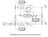
- FIG. 2 shows a two-inertia model of a positioning control object used in the present invention.
- the reference numerals in the figure are as follows, and the nonlinear elements are indicated by bold blocks.
- J m Motor shaft inertia moment
- D m Motor shaft viscous friction coefficient
- J l Load shaft inertia moment
- D l Load shaft viscous friction coefficient
- ⁇ g ( ⁇ tw ) Non-linear spring characteristics of reduction gear
- D g Reduction gear viscosity Friction coefficient
- N Reduction ratio
- K t Motor torque constant ⁇ m : Motor shaft position ⁇ m : Motor speed ⁇ l : Load shaft position ⁇ l : Load speed ⁇ tw : Torsion angle ⁇ Sync ( ⁇ m ): Angle transmission error Relative rotation synchronization component ⁇ m ( ⁇ m ): Motor shaft nonlinear friction torque ⁇ l ( ⁇ l )
- nonlinear spring characteristics, angle transmission error, and nonlinear friction of the wave gear device are modeled as nonlinear elements included in the controlled object.
- Design parameters are used for linear parameters other than these nonlinear elements, and the constants are shown in Table 2.
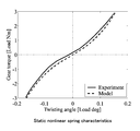
- the non-linear spring characteristic ⁇ g ( ⁇ tw ) is expressed by the following expression (1) by a third-order polynomial that has no hysteresis and can be differentiated with respect to the torsion angle ⁇ tw between the motor and the load shaft.
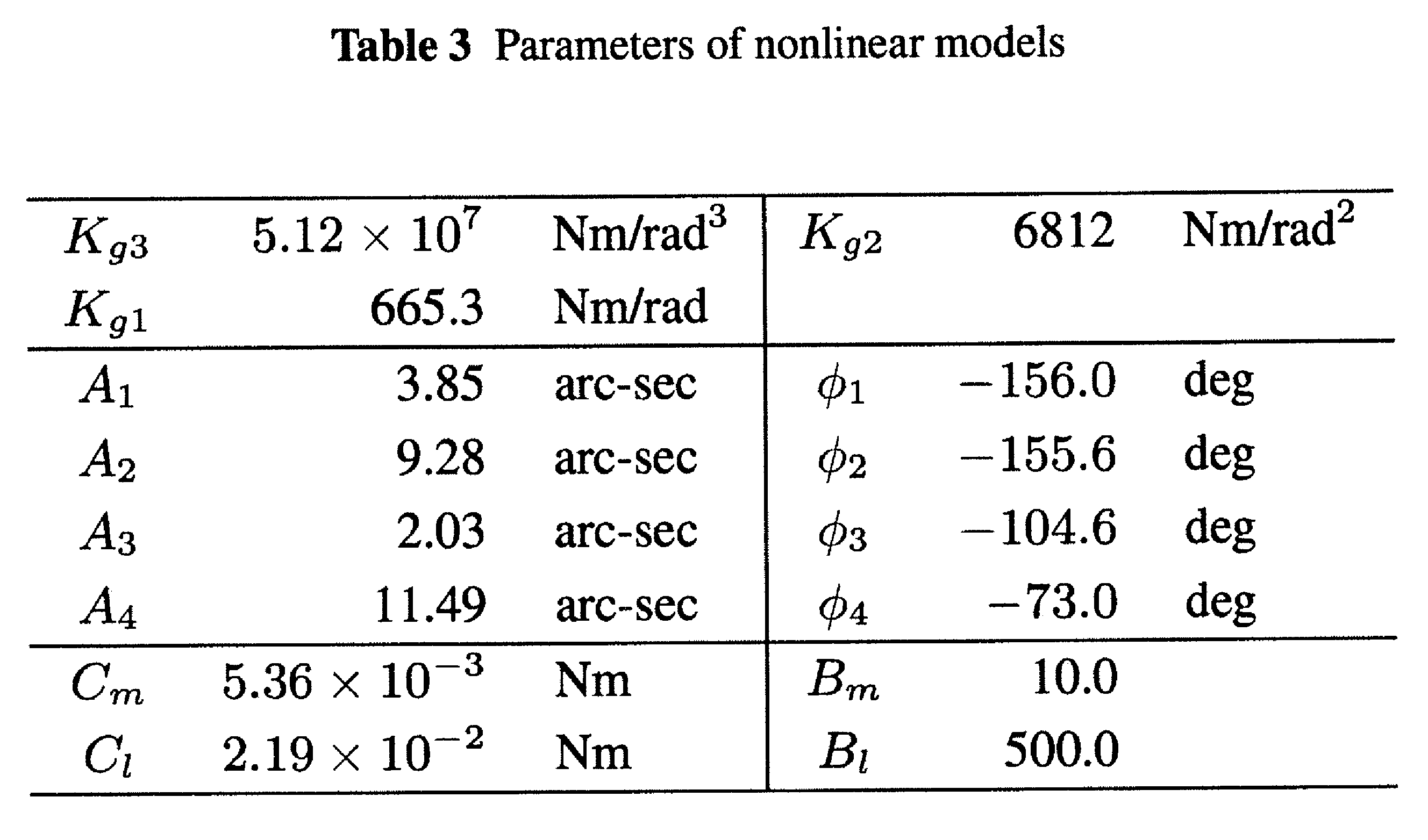
- K g3 to K g1 are coefficients of each degree of the polynomial, and were determined by the least square method for the measurement result.
- the value of each parameter is shown in Table 3, and the model of the identified nonlinear spring characteristic is also shown with a broken line (Model) in FIG.
- angle transmission error modeling In general, the angle transmission error ⁇ TE is defined by the following equation (2) using the motor shaft position ⁇ m , the load shaft position ⁇ l , and the reduction ratio N.
- the relative rotational synchronization component ⁇ Sync of the angle transmission error to be compensated in the present invention is the cumulative pitch error of the flex spline (FS) and the circular spline (CS) constituting the wave gear device, the wave gear device and the load. It is a component generated by an assembly error such as an axial misalignment, and is generated in synchronization with the relative rotation of the wave generator (WG), FS, and CS. Therefore, ⁇ Sync can be expressed as a sum of a motor shaft synchronization component ⁇ TEM , a load shaft synchronization component ⁇ TEL , and an FS-WG relative synchronization component ⁇ TARE as a superposition of sine waves with ⁇ m as an argument.
- FIG. 4 shows the waveform and spectrum waveform of the actual machine relative rotation synchronization component.
- the upper solid line (Experiment) is an angle transmission error waveform obtained by continuously measuring a minute feed operation of 3.6 deg at the motor shaft angle for one rotation of the load shaft
- the lower solid line is an upper spectrum waveform.
- arc-sec on the vertical axis is a unit of angle
- 1 deg 3600 arc-sec.
- the relative rotation synchronization component has a large amplitude of the first to fourth order components with respect to the motor rotation, and exists up to about the 20th order.
- the fourth and lower order components are modeled here for compensation. Use.
- the upper dashed line (Model) and the lower bold line (Model) in FIG. 4 show waveforms modeled by extracting components of the fourth and lower orders, and Table 3 shown above shows identification parameters A 1 to A 4 , ⁇ for each order. show 1 ⁇ ⁇ 4.
- Nonlinear friction is broadly classified into static friction that depends on the speed that is dominant in the positioning operation of a long stroke, and dynamic friction that depends on displacement with elasticity that is dominant in a small stroke.
- static friction depending on speed is modeled.
- the actual machine friction characteristic by the constant speed driving test in which the motor torque is measured during the constant motor speed and the motor torque is regarded as the friction torque is shown by a solid line (Experiment) in FIG. From the figure, there is coulomb friction of about 0.4 Nm along with viscous friction, and its influence cannot be ignored compared with the maximum load torque of 3.3 Nm of the wave gear device.
- C m nonlinear frictional force of motor shaft
- B m positive / negative switching speed of frictional force when speed is near zero
- C 1 Nonlinear frictional force of the load shaft
- B 1 Positive / negative switching speed of the frictional force when the speed is near zero
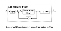
- FIG. 6 is a conceptual block diagram of input / output linearization based on a strict linearization method.
- linearization feedback ⁇ (x) having a state quantity x as an argument and by adding the input variable ⁇ (x), is a characteristic of the input ⁇ enlargement system to output y intended to d n y / dt n.
- the dead time element e ⁇ Ls is not included in the above equation in order to compensate the influence by the Smith method described later.
- ⁇ (x) includes a first-order derivative of ⁇ g ( ⁇ tw ), a second-order derivative of ⁇ Sync, and a first-order derivative of ⁇ l ( ⁇ l ).
- the differential coefficients d ⁇ g ( ⁇ tw ) / dt, d 2 ⁇ Sync ( ⁇ m ) / dt 2 , and d ⁇ l ( ⁇ l ) / dt for each nonlinear element are (1 ), (3), and (5) are used as follows.
- ⁇ (x) includes the total state quantity x from the equation (9), but in the positioning control system of the present invention which is a semi-closed control system, Since the state quantity of the load shaft cannot be detected, it cannot be mounted as it is. Furthermore, since there is a finite dead time element, compensation is also necessary. Therefore, the feedback (FB) type linearization compensation in FIG. 6 is equivalently converted to the feed forward (FF) type linearization compensation to cope with the implementation in the semi-closed control system and the dead time compensation.
- the nonlinear model “Nonlinear Plant Mdl.” To be controlled is held inside the compensator, and the state quantity calculated forward
- the estimated value x * is used to calculate the FF current command i * ref and the FF motor position command ⁇ * m that is input to the FB type control system FB (s).
- the Smith method is applied, and ⁇ * m is delayed by a dead time L to compensate for the influence.
- the angular transmission error relative rotation synchronization component causes steady deviation of the load position and vibration excitation, so when setting the positioning feed angle for actual machine verification, consider the gear meshing condition of the wave gear device. There is a need to. Therefore, for the variation evaluation of the static load position steady-state deviation, the evaluation is performed with the feed angle at which the gear meshing changes so that the relative rotation synchronization component at the time of setting becomes a different value for each positioning.
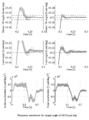
- the control system of the present invention can significantly suppress the overshoot compared to the conventional control system.
- the load position response of the conventional control system in the middle left stage the positioning response and the load settling position vary due to the angle transmission error.
- the FF motor position compensation that shifts the motor position in the upper part of the figure by the angle transmission error is input, so that the angle transmission error is compensated and the load settling position varies as in the middle stage. Is compressed.
- vibration components around 0.02 to 0.05 s at the start of positioning and 0.2 s at the settling time are suppressed.
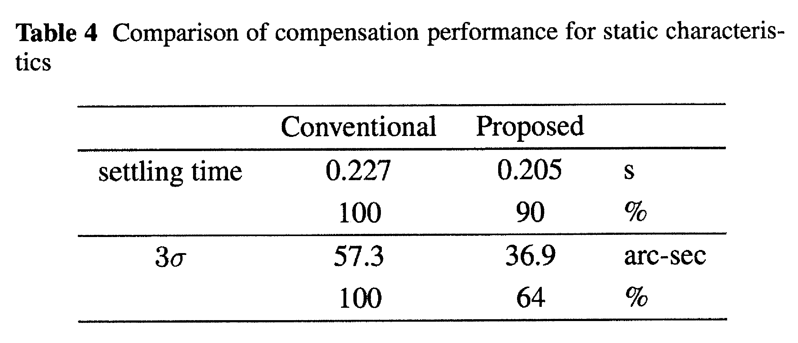
- the average positioning time of 240 times and the variation in the steady deviation of the load position were compared using the standard deviation of 3 ⁇ as an index.
- Table 4 shows a comparison of each index value. The lower part of each item is an evaluation value standardized on the basis of the conventional control system. From the table, the control system of the present invention can shorten the positioning time to 90% compared to the conventional control system, and the load position varies. Can be compressed to 64%.
- FIG. 9 shows the results of an experiment conducted with the feed angle 43.2 Load deg under the same conditions as in the evaluation of the static compensation accuracy.
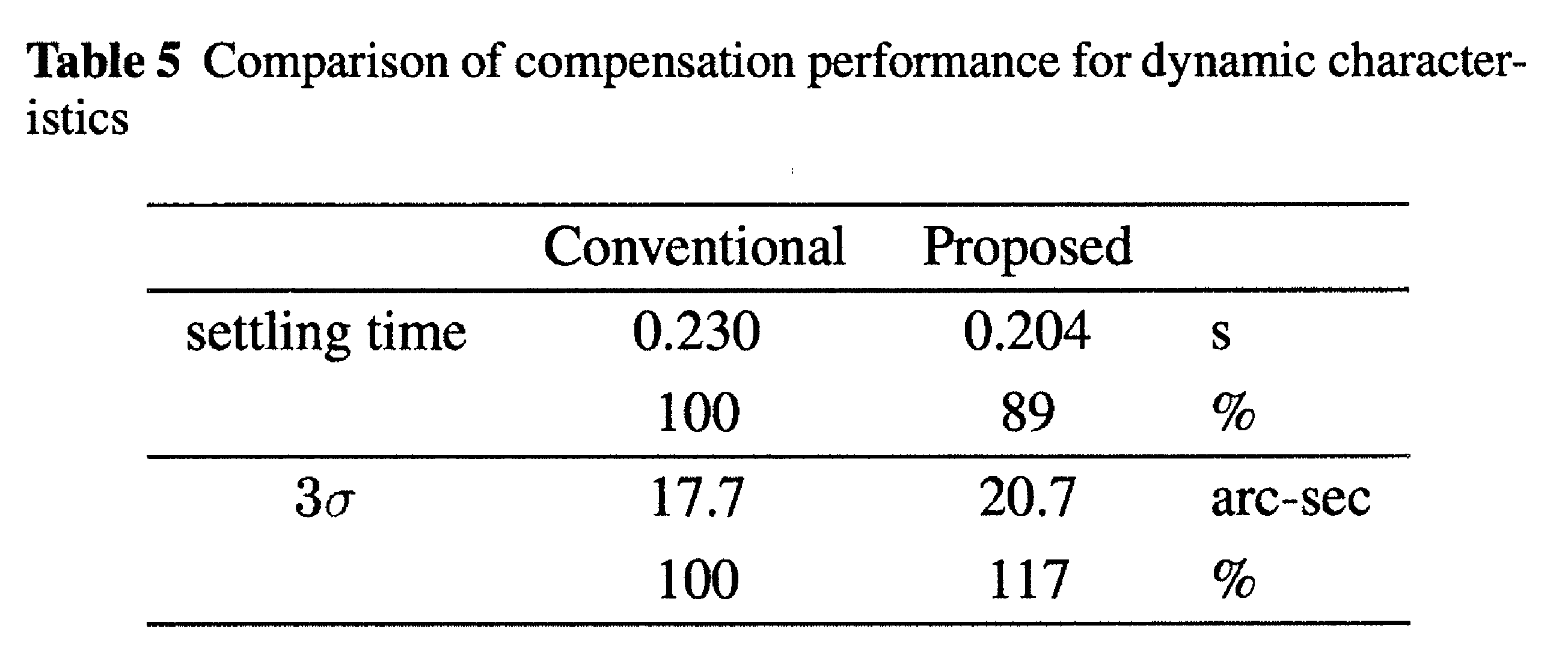
- Table 5 shows the reputation evaluation of the same indicators as the characteristics.
- the arrangement and line type in the figure are the same as those in FIG.
- the overshoot is significantly suppressed in the control system of the present invention, as in the static characteristic compensation experiment, and the positioning time can also be shortened from Table 5.
- the variation 3 ⁇ in Table 5 is larger than that in the conventional control system. This is because, at a feed angle where the meshing of the gears is the same, the relative rotation synchronization component for each positioning takes only the same value, and no variation due to the relative rotation synchronization component occurs regardless of the presence or absence of compensation. Because it becomes.
- the average response of load acceleration in the lower part of the figure vibrations that are not found in the static compensation evaluation response shown in the lower part of FIG.
- the control system of the present invention suppresses overshoot due to nonlinear springs and nonlinear friction, shortens the positioning time, and suppresses variation in load position during settling due to angle transmission error and vibration during response.
- the positioning time is shortened to 90% by suppressing overshoot during settling, the variation during settling is reduced to 64%, and the vibration of the load shaft during positioning response is reduced. It became feasible.
Landscapes
- Engineering & Computer Science (AREA)
- Power Engineering (AREA)
- Physics & Mathematics (AREA)
- General Physics & Mathematics (AREA)
- Automation & Control Theory (AREA)
- Feedback Control In General (AREA)
- Control Of Position Or Direction (AREA)
Abstract
Description
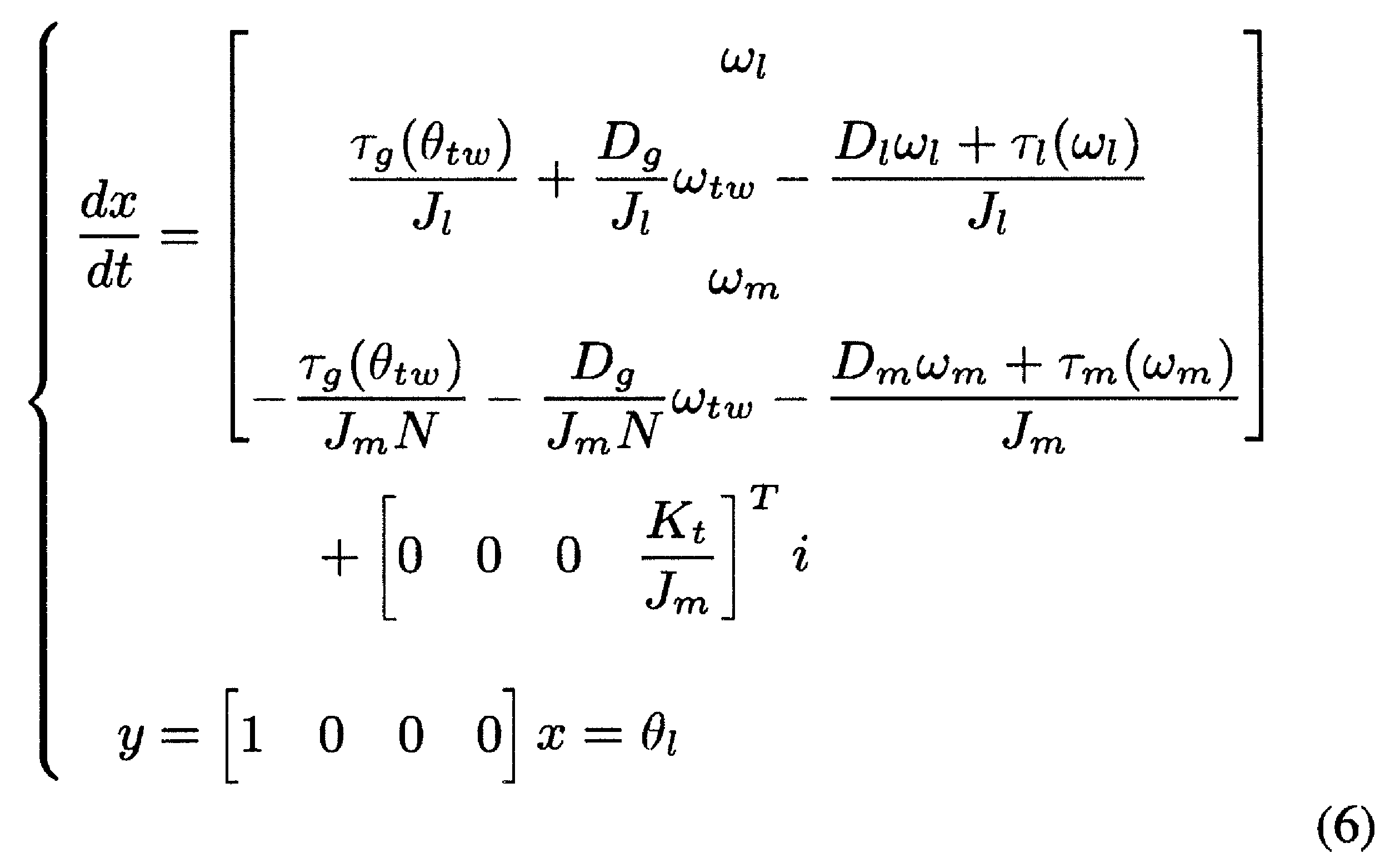
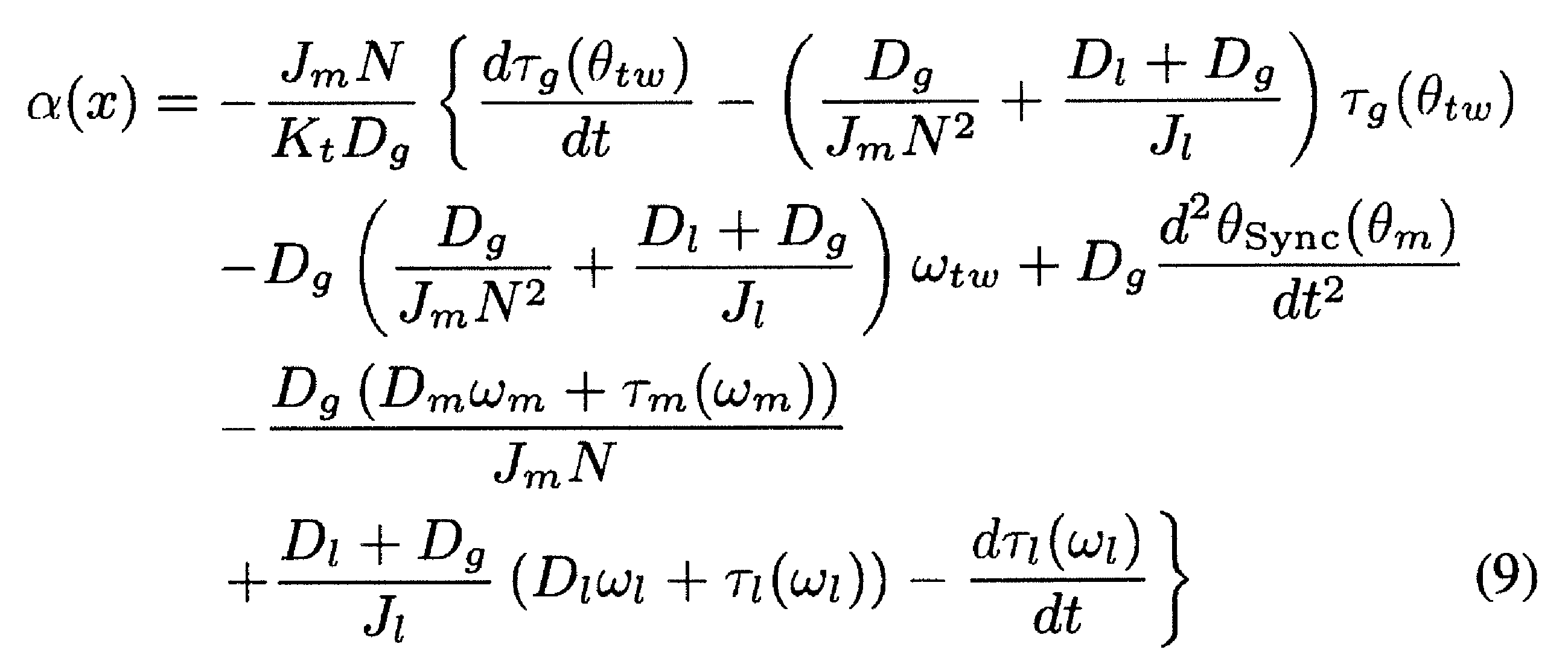





図1は、本発明の制御対象である、波動歯車装置を減速機として含むアクチュエータの概略図である。表1にはアクチュエータの主要諸元を示してある。

本発明では、厳密な線形化手法の適用を考慮して、次のようにしてアクチュエータ1のモデル化を行う。
Jm:モータ軸慣性モーメント
Dm:モータ軸粘性摩擦係数
Jl:負荷軸慣性モーメント
Dl:負荷軸粘性摩擦係数
τg(θtw):減速機の非線形ばね特性
Dg:減速機の粘性摩擦係数
N:減速比
Kt:モータトルク定数
θm:モータ軸位置
ωm:モータ速度
θl:負荷軸位置
ωl:負荷速度
θtw:ねじれ角
θSync(θm):角度伝達誤差の相対回転同期成分
τm(ωm):モータ軸非線形摩擦トルク
τl(ωl):負荷軸非線形摩擦トルク
i:モータトルク電流指令値
e-Ls:演算時間や通信時間による電流指令値から実電流までのむだ時間要素

非線形ばね特性を測定するために、モータ軸をサーボロックした状態で負荷軸にアームと重りを取り付けて重力による負荷トルクを加え、負荷トルクとモータ・負荷軸間のねじれ角度を測定した。その際、負荷トルクを徐々に大きくした後、徐々に逆方向の負荷トルクを与え、さらに無負荷状態とするまでを、一連の非線形ばね特性測定とした。その静的な非線形ばね特性を、図3の実線(Experiment)で示す。この図から、ばね特性がヒステリシスを含む非線形な特性を示すことが明確である。

一般に、角度伝達誤差θTEは、モータ軸位置θm、負荷軸位置θl、減速比Nを用いて次の(2)式で定義される。


ここで、k:モータ回転に対する高調波次数
Ak:各次数成分の振幅
φk:各次数成分の位相
非線形摩擦は、長ストロークの位置決め動作で支配的な速度に依存する静的摩擦と、微小ストロークで支配的な弾性を伴う変位に依存する動的摩擦に大別される。本発明では、モータ・負荷軸共に長ストロークと考えられる位置決めを対象とするため、速度に依存する静的摩擦をモデル化する。一定モータ速度中にモータトルクを測定し、モータトルクを摩擦トルクと見做した一定速度駆動試験による実機摩擦特性を、図5の実線(Experiment)で示す。図から、粘性摩擦と共に約0.4Nmのクーロン摩擦が存在しており、本波動歯車装置の最大負荷トルク3.3Nmと比較して、その影響は無視できない。そこで、速度の正負が切り替わる領域で滑らかに接続するようにtanh関数を用いて非線形ばね特性に対するモデル化と同様に、微分可能な関数としてモータ軸摩擦τm(ωm)、負荷摩擦τl(ωl)を次の(4)式、(5)式でそれぞれ表現する。

Bm:速度が零付近における摩擦力の正負の切り替え速度

Bl:速度が零付近における摩擦力の正負の切り替え速度
図6は厳密な線形化手法による入出力線形化の概念ブロック図であり、非線形要素を含む制御対象「Nonlinear Plant」に対して、その状態量xを引数とする線形化フィードバックα(x)と入力変数β(x)を付加することで、拡大系の入力νから出力yまでの特性をdny/dtnとするものである。






以上のように構築した厳密な線形化手法に基づく非線形補償を行う位置決め制御システムを実機位置決め制御系に実装し、実験によりその補償効果を検証した。
制御対象として取り扱う非線形要素のうち、角度伝達誤差相対回転同期成分は負荷位置の定常偏差や振動励起の原因となるため、実機検証の位置決め送り角度設定に際しては、波動歯車装置の歯車かみ合い条件を考慮する必要がある。そこで、静的な負荷位置定常偏差のばらつき評価に対しては、整定時の相対回転同期成分が位置決め毎に異なる値となるように、歯車のかみ合わせが変化する送り角度で評価する。
静的補償特性
本発明の制御系による静的補償精度を評価すべく、送り角度43.56Load degの連続一方向位置決め動作(240回、送りインターバル1.25s)を行った。図8の上段にモータ位置、中段に負荷位置、下段に負荷加速度の、それぞれ12回分の応答を抽出して重ね描きしたものを示す。図中、左列が従来制御系、右列が本発明の制御系の応答であり、太線は240回の応答の平均値、水平一点鎖線は目標位置を示す。さらに、モータ位置応答の水平破線は、目標整定範囲と設定したモータ軸+-10Motor puls=32.4Load arc-secを示す。
動的補償特性を評価すべく、送り角度43.2Load degで、他の条件は静的補償精度の評価の場合と同様として実験を行った結果を図9に示し、静的補償特性と同じ指標の定評評価を表5に示す。ここで、図の配置および線種は図8と同等である。
Claims (3)
- モータの回転を波動歯車装置を介して減速して負荷軸に伝達するアクチュエータを駆動制御して、前記負荷軸の位置決め制御を行う位置決めシステムにおいて、
モータ軸位置θmをフィードバックして前記負荷軸の位置決め制御を行うセミクローズドループ型のフィードバック制御器と、
前記アクチュエータの非線形要素である、非線形ばね特性、相対回転同期成分および非線形摩擦のうち、少なくとも、前記相対回転同期成分あるいは前記非線形摩擦に起因する前記負荷軸の位置決め誤差を補償するためのフィードフォワード型線形化補償器とを有し、
補償対象の前記非線形要素は、相対回転同期成分のみの場合、非線形摩擦のみの場合、前記相対回転同期成分および前記非線形摩擦を含む場合、並びに、非線形ばね特性、前記相対回転同期成分および前記非線形摩擦を含む場合のうちのいずれかであり、
前記フィードフォワード型線形化補償器は、厳密な線形化手法に基づくフィードバック型線形化補償器に、制御対象の前記アクチュエータを表す非線形プラントモデルを組み込むことにより、当該フィードバック型線形化補償器をフィードフォワード型に等価変換したものであり、
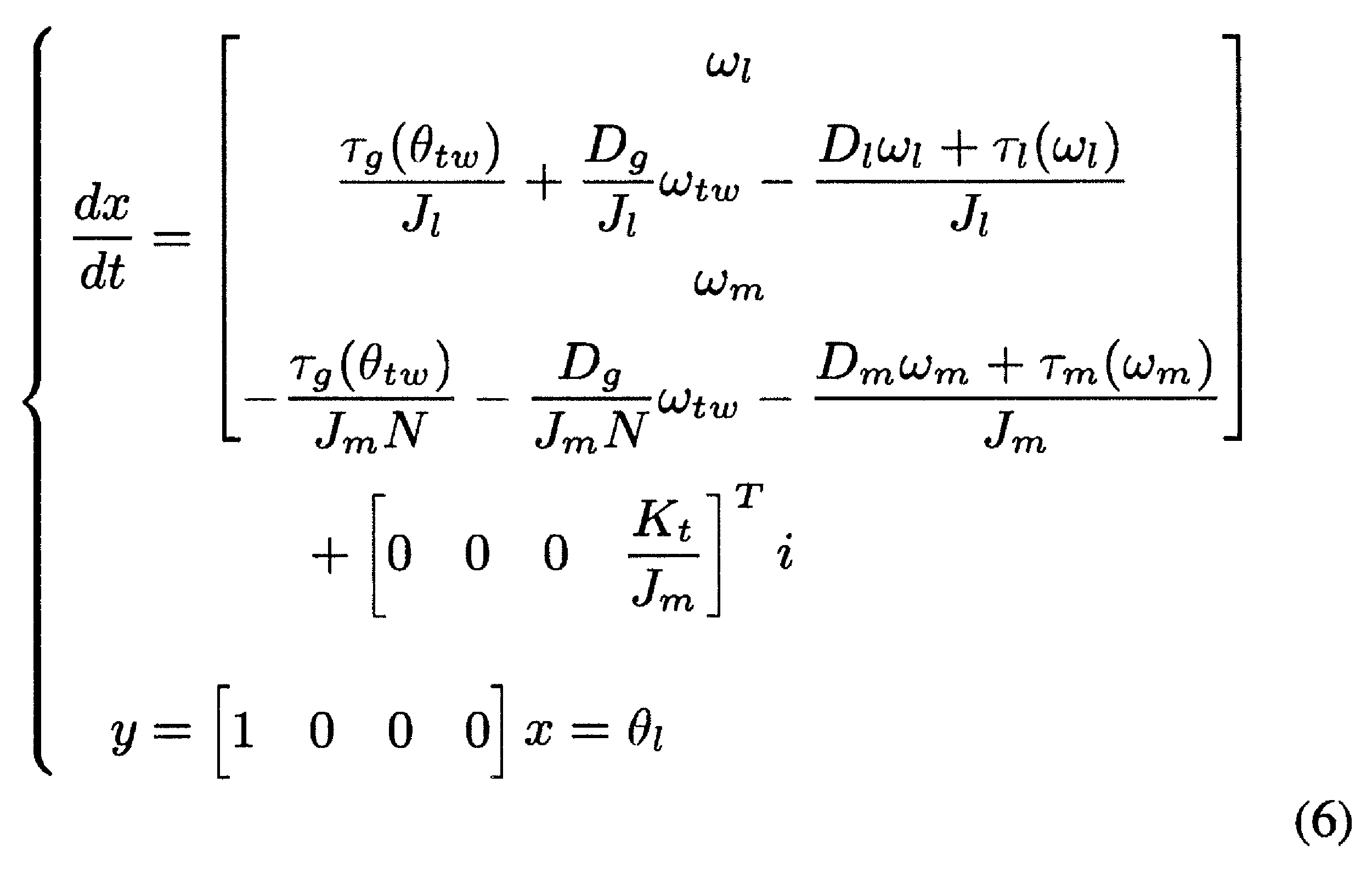
前記非線形プラントモデルは、状態量をx=[θl,ωl,θm,ωm]Tとして、(6)式で示す非線形状態方程式で規定されるものであり、
ここで、
Jm:モータ軸慣性モーメント
Dm:モータ軸粘性摩擦係数
Jl:負荷軸慣性モーメント
Dl:負荷軸粘性摩擦係数
τg(θtw):減速機の非線形ばね特性
Dg:減速機の粘性摩擦係数
N:減速比
Kt:モータトルク定数
θm:モータ軸位置
ωm:モータ速度
θl:負荷軸位置
ωl:負荷速度
θtw:ねじれ角
θSync(θm):角度伝達誤差の相対回転同期成分
τm(ωm):モータ軸非線形摩擦トルク
τl(ωl):負荷軸非線形摩擦トルク
i:モータトルク電流指令値
前記フィードバック型線形化補償器は、前記非線形プラントモデルに対して、その状態量xを引数とする線形化フィードバックα(x)と入力変数β(x)を付加することで、拡大系の入力νから出力yまでの特性をd3y/dt3=νとしたものであり、前記線形化フィードバックα(x)は(9)式で規定され、前記入力変数β(x)は(10)式で規定されており、
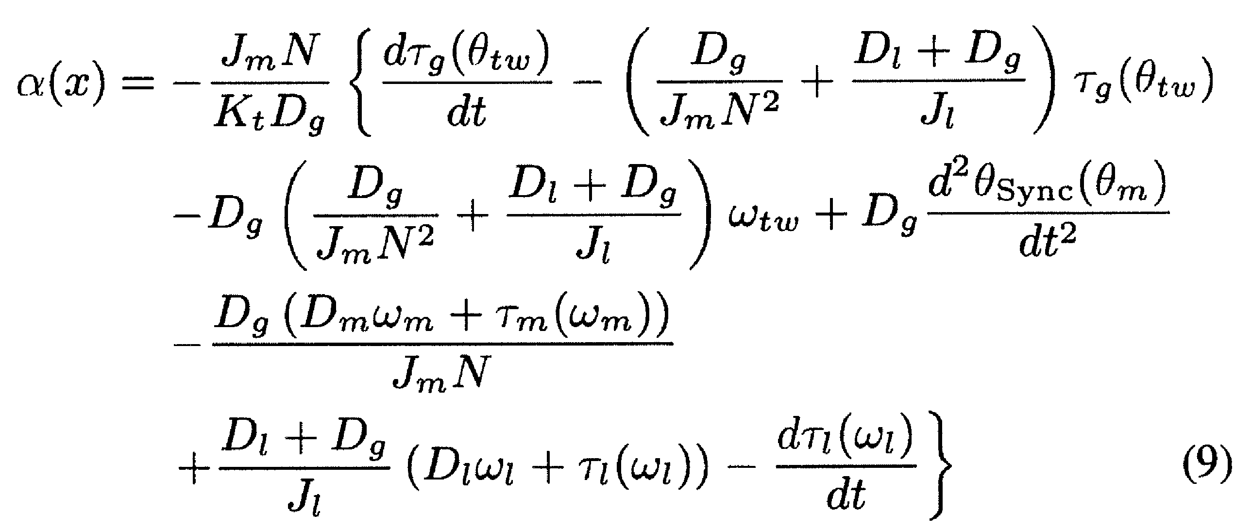

前記フィードフォワード型線形化補償器は、負荷加加速度指令(ジャーク指令)jrefを前記入力νとし、前記非線形プラントモデルに基づき計算した状態量推定値x*を用いて、前記出力yであるフィードフォワード電流指令i* refを計算すると共に、前記フィードバック制御器への入力となるフィードフォワードモータ位置指令θ* mを計算するものであり、
前記非線形ばね特性は、(1)式により規定される、前記波動歯車装置の負荷トルクに対する非線形ばね特性であり、前記アクチュエータに負荷トルクを加えて負荷トルクとモータ・負荷軸間のねじれ角度の関係を測定して得られる実機非線形ばね特性を再現できるように、(1)式の各次数の係数Kg1、Kg2、Kg3が設定されており、

前記相対回転同期成分は、前記波動歯車装置の角度伝達誤差のうち、モータ軸の回転に同期して発生するモータ軸同期成分θTEMを相対回転同期成分として(3)式により規定される角度伝達誤差成分であり、前記アクチュエータの微小角度送り動作整定時の角度伝達誤差を負荷軸1回転分測定し、モータ位置に対する実機相対回転同期成分をフーリエ変換したスペクトル解析を行い、これに基づき、実機相対回転同期成分を再現できるように、(3)式におけるモータ回転の整数倍高調波成分の振幅Akおよび位相φkが設定されており、

前記非線形摩擦は、前記波動歯車装置の非線形摩擦のうち、速度に依存する静的摩擦であるモータ軸摩擦τm(ωm)および負荷軸摩擦τl(ωl)を、それぞれ(4)式および(5)式で規定したものであり、一定モータ速度中にモータトルクを測定し、モータトルクを摩擦トルクと見做した一定速度駆動試験によって得られる実機摩擦特性を再現できるように、(4)式、(5)式の各パラメータCm、Cl、Bm、Blが設定されていることを特徴とするアクチュエータの位置決め制御システム。

ここで、Cm:モータ軸の非線形摩擦力
Bm:速度が零付近における摩擦力の正負の切り替え速度

ここで、Cl:負荷軸の非線形摩擦力
Bl:速度が零付近における摩擦力の正負の切り替え速度 - 請求項1において、
前記フィードフォワード型線形化補償器は、前記非線形ばね特性、前記相対回転同期成分および前記非線形摩擦に起因する前記負荷軸の位置決め誤差を補償することを特徴とするアクチュエータの位置決め制御システム。 - 請求項1または2において、
前記フィードフォワード型線形化補償器は、スミス法により、前記フィードフォワードモータ位置指令θ* mを、予め設定したむだ時間L分だけ遅らせて、前記フィードバック制御器に供給することを特徴とするアクチュエータの位置決め制御システム。
Priority Applications (4)
| Application Number | Priority Date | Filing Date | Title |
|---|---|---|---|
| JP2013540498A JP5839510B2 (ja) | 2011-10-24 | 2011-10-24 | 波動歯車装置を備えたアクチュエータの位置決め制御システム |
| PCT/JP2011/005951 WO2013061362A1 (ja) | 2011-10-24 | 2011-10-24 | 波動歯車装置を備えたアクチュエータの位置決め制御システム |
| DE112011105755.5T DE112011105755B4 (de) | 2011-10-24 | 2011-10-24 | Positionierungssteuersystem für einen mit einem Wellgetriebe ausgestatteten Aktuator |
| US14/240,752 US9075399B2 (en) | 2011-10-24 | 2011-10-24 | Positioning control system for actuator provided with wave gear device |
Applications Claiming Priority (1)
| Application Number | Priority Date | Filing Date | Title |
|---|---|---|---|
| PCT/JP2011/005951 WO2013061362A1 (ja) | 2011-10-24 | 2011-10-24 | 波動歯車装置を備えたアクチュエータの位置決め制御システム |
Publications (1)
| Publication Number | Publication Date |
|---|---|
| WO2013061362A1 true WO2013061362A1 (ja) | 2013-05-02 |
Family
ID=48167235
Family Applications (1)
| Application Number | Title | Priority Date | Filing Date |
|---|---|---|---|
| PCT/JP2011/005951 Ceased WO2013061362A1 (ja) | 2011-10-24 | 2011-10-24 | 波動歯車装置を備えたアクチュエータの位置決め制御システム |
Country Status (4)
| Country | Link |
|---|---|
| US (1) | US9075399B2 (ja) |
| JP (1) | JP5839510B2 (ja) |
| DE (1) | DE112011105755B4 (ja) |
| WO (1) | WO2013061362A1 (ja) |
Cited By (3)
| Publication number | Priority date | Publication date | Assignee | Title |
|---|---|---|---|---|
| CN110285203A (zh) * | 2019-06-12 | 2019-09-27 | 北京工业大学 | 一种谐波减速器多齿啮合载荷分布模型设计方法 |
| JP2020052781A (ja) * | 2018-09-27 | 2020-04-02 | 日本電産サンキョー株式会社 | サーボ制御装置及びサーボ制御方法 |
| CN117353616A (zh) * | 2023-12-04 | 2024-01-05 | 合肥安迅精密技术有限公司 | 直线电机的摩擦力前馈补偿方法及系统、存储介质 |
Families Citing this family (11)
| Publication number | Priority date | Publication date | Assignee | Title |
|---|---|---|---|---|
| US9729094B2 (en) * | 2013-06-10 | 2017-08-08 | Meidensha Corporation | Automatic suppression device for cyclic disturbance |
| CN104993766B (zh) * | 2015-08-05 | 2017-06-30 | 南京埃斯顿自动控制技术有限公司 | 一种二质量系统谐振抑制方法 |
| JP6898649B2 (ja) * | 2015-08-07 | 2021-07-07 | 学校法人慶應義塾 | 振動制御装置、振動制御方法、振動制御システム、プログラム及び記録媒体 |
| DE102016213596B4 (de) * | 2016-07-25 | 2019-02-21 | SmarAct Holding GmbH | Verfahren und Vorrichtung zur linearen und/oder rotatorischen Positionierung |
| WO2018061096A1 (ja) * | 2016-09-27 | 2018-04-05 | 株式会社ハーモニック・ドライブ・システムズ | H∞制御による波動歯車装置を備えたアクチュエータの位置決め制御装置 |
| US10254740B2 (en) | 2016-09-27 | 2019-04-09 | Harmonic Drive Systems Inc. | Positioning control device for actuator provided with strain wave gearing using full-closed control with state observer |
| JP6867885B2 (ja) * | 2017-06-05 | 2021-05-12 | 川崎重工業株式会社 | 角度伝達誤差同定システム、角度伝達誤差同定方法及びロボットシステム |
| JP6568148B2 (ja) * | 2017-06-06 | 2019-08-28 | ファナック株式会社 | サーボモータ制御装置 |
| CN107203184B (zh) * | 2017-06-20 | 2019-04-16 | 南京理工大学 | 直线舵机电动加载系统的动态控制方法 |
| CN108983597B (zh) * | 2018-08-23 | 2021-03-12 | 广东电网有限责任公司 | 一种近似纯滞后的方法及装置 |
| CN118153447B (zh) * | 2024-03-25 | 2025-06-03 | 北京工业大学 | 协作机器人关节数字孪生体构建及应用方法、设备、介质及产品 |
Citations (3)
| Publication number | Priority date | Publication date | Assignee | Title |
|---|---|---|---|---|
| JPS6366611A (ja) * | 1986-09-08 | 1988-03-25 | Yokogawa Electric Corp | マニピユレ−タのシミユレ−シヨン方法 |
| JP2009187404A (ja) * | 2008-02-07 | 2009-08-20 | Harmonic Drive Syst Ind Co Ltd | アクチュエータの角度伝達誤差補償方法 |
| WO2010116607A1 (ja) * | 2009-04-07 | 2010-10-14 | 株式会社ハーモニック・ドライブ・システムズ | 波動歯車装置の角度伝達誤差補償方法 |
Family Cites Families (5)
| Publication number | Priority date | Publication date | Assignee | Title |
|---|---|---|---|---|
| WO2000019288A1 (en) * | 1998-09-28 | 2000-04-06 | Kabushiki Kaisha Yaskawa Denki | Position controller |
| JP3073971B2 (ja) | 1998-12-22 | 2000-08-07 | 京セラミタ株式会社 | 画像形成装置 |
| US8043029B2 (en) | 2008-10-10 | 2011-10-25 | Chen Man Kim | Packer structure |
| JP5453606B2 (ja) | 2010-04-09 | 2014-03-26 | 株式会社ハーモニック・ドライブ・システムズ | 波動歯車装置を備えたアクチュエータの位置決め制御方法 |
| JP5656193B2 (ja) * | 2011-04-20 | 2015-01-21 | 株式会社ハーモニック・ドライブ・システムズ | 波動歯車装置を備えたアクチュエータの位置決め装置 |
-
2011
- 2011-10-24 JP JP2013540498A patent/JP5839510B2/ja active Active
- 2011-10-24 US US14/240,752 patent/US9075399B2/en active Active
- 2011-10-24 WO PCT/JP2011/005951 patent/WO2013061362A1/ja not_active Ceased
- 2011-10-24 DE DE112011105755.5T patent/DE112011105755B4/de active Active
Patent Citations (3)
| Publication number | Priority date | Publication date | Assignee | Title |
|---|---|---|---|---|
| JPS6366611A (ja) * | 1986-09-08 | 1988-03-25 | Yokogawa Electric Corp | マニピユレ−タのシミユレ−シヨン方法 |
| JP2009187404A (ja) * | 2008-02-07 | 2009-08-20 | Harmonic Drive Syst Ind Co Ltd | アクチュエータの角度伝達誤差補償方法 |
| WO2010116607A1 (ja) * | 2009-04-07 | 2010-10-14 | 株式会社ハーモニック・ドライブ・システムズ | 波動歯車装置の角度伝達誤差補償方法 |
Non-Patent Citations (2)
| Title |
|---|
| GODLER IVAN: "Haguruma Gensokuki no Kakudo Dentatsu Gosa ni Kiin suru Sokudo Hendo no Yokusei Seigyo", JOURNAL OF THE SOCIETY OF INSTRUMENT AND CONTROL ENGINEERS, vol. 39, no. 10, October 2000 (2000-10-01), pages 651 - 654 * |
| TOSHIAKI MIYAZAKI: "Robust Speed Control for Robot Arm with Angular Transmission Error of Gear", DAI 16 KAI ANNUAL CONFERENCE OF THE ROBOTICS SOCIETY OF JAPAN YOKOSHU, vol. 1L13, 18 September 1998 (1998-09-18), pages 443 - 444 * |
Cited By (6)
| Publication number | Priority date | Publication date | Assignee | Title |
|---|---|---|---|---|
| JP2020052781A (ja) * | 2018-09-27 | 2020-04-02 | 日本電産サンキョー株式会社 | サーボ制御装置及びサーボ制御方法 |
| CN110955192A (zh) * | 2018-09-27 | 2020-04-03 | 日本电产三协株式会社 | 伺服控制装置、机器人及伺服控制方法 |
| JP7338960B2 (ja) | 2018-09-27 | 2023-09-05 | ニデックインスツルメンツ株式会社 | サーボ制御装置及びサーボ制御方法 |
| CN110285203A (zh) * | 2019-06-12 | 2019-09-27 | 北京工业大学 | 一种谐波减速器多齿啮合载荷分布模型设计方法 |
| CN117353616A (zh) * | 2023-12-04 | 2024-01-05 | 合肥安迅精密技术有限公司 | 直线电机的摩擦力前馈补偿方法及系统、存储介质 |
| CN117353616B (zh) * | 2023-12-04 | 2024-02-09 | 合肥安迅精密技术有限公司 | 直线电机的摩擦力前馈补偿方法及系统、存储介质 |
Also Published As
| Publication number | Publication date |
|---|---|
| US9075399B2 (en) | 2015-07-07 |
| JP5839510B2 (ja) | 2016-01-06 |
| US20140203752A1 (en) | 2014-07-24 |
| DE112011105755B4 (de) | 2024-08-01 |
| DE112011105755T5 (de) | 2014-09-18 |
| JPWO2013061362A1 (ja) | 2015-04-02 |
Similar Documents
| Publication | Publication Date | Title |
|---|---|---|
| JP5839510B2 (ja) | 波動歯車装置を備えたアクチュエータの位置決め制御システム | |
| JP5207071B2 (ja) | 波動歯車装置の角度伝達誤差補償方法 | |
| Feliu et al. | Passivity-based control of single-link flexible manipulators using a linear strain feedback | |
| JP5656193B2 (ja) | 波動歯車装置を備えたアクチュエータの位置決め装置 | |
| JP2020078247A (ja) | 駆動装置、アクチュエータユニット、ロボット装置、駆動装置の制御方法、アクチュエータユニットの制御方法、ロボット装置の制御方法 | |
| JP2015030076A (ja) | ロボット制御装置 | |
| JP5453606B2 (ja) | 波動歯車装置を備えたアクチュエータの位置決め制御方法 | |
| JP2014034101A (ja) | ロボット制御装置 | |
| CN105629719A (zh) | 马达控制装置及马达控制方法 | |
| Yamada et al. | Joint torque control for two-inertia system with encoders on drive and load sides | |
| Erkorkmaz et al. | Control of ball screw drives based on disturbance response optimization | |
| JP6371010B1 (ja) | 状態オブザーバ併用型フルクローズド制御による波動歯車装置を備えたアクチュエータの位置決め制御装置 | |
| CN102820844A (zh) | 一种柔性臂振动抑制方法 | |
| US9876448B2 (en) | Position control apparatus | |
| JP5441944B2 (ja) | モータ制御装置 | |
| EP3968513A1 (en) | Motor control system, motor control method, and program | |
| JP2020095718A (ja) | リニアモータステージの制御方法及び制御装置 | |
| JP6466588B2 (ja) | H∞制御による波動歯車装置を備えたアクチュエータの位置決め制御装置 | |
| Yamamoto et al. | Compensation for synchronous component of angular transmission errors in harmonic drive gearings | |
| Yamada et al. | Proposal of self resonance cancellation control without using drive-side information | |
| JP3360935B2 (ja) | 電動機制御系における機械共振検出装置及び制振制御装置 | |
| Iwasaki | Robust full-closed control-based vibration suppression for positioning devices with strain wave gearing | |
| Hosseinkhani | Control methods for improving tracking accuracy and disturbance rejection in ball screw feed drives | |
| WO2026083675A1 (ja) | 減速機の角度伝達誤差の推定方法及び推定装置、並びにモータの制御方法及び制御装置 | |
| Maeda et al. | Improvement of settling performance by initial value compensation considering rolling friction characteristic |
Legal Events
| Date | Code | Title | Description |
|---|---|---|---|
| 121 | Ep: the epo has been informed by wipo that ep was designated in this application |
Ref document number: 11874598 Country of ref document: EP Kind code of ref document: A1 |
|
| ENP | Entry into the national phase |
Ref document number: 2013540498 Country of ref document: JP Kind code of ref document: A |
|
| WWE | Wipo information: entry into national phase |
Ref document number: 14240752 Country of ref document: US |
|
| WWE | Wipo information: entry into national phase |
Ref document number: 112011105755 Country of ref document: DE Ref document number: 1120111057555 Country of ref document: DE |
|
| 122 | Ep: pct application non-entry in european phase |
Ref document number: 11874598 Country of ref document: EP Kind code of ref document: A1 |