WO2013042689A1 - 硬質基板積層体の加工方法及び板状製品の製造方法 - Google Patents
硬質基板積層体の加工方法及び板状製品の製造方法 Download PDFInfo
- Publication number
- WO2013042689A1 WO2013042689A1 PCT/JP2012/073946 JP2012073946W WO2013042689A1 WO 2013042689 A1 WO2013042689 A1 WO 2013042689A1 JP 2012073946 W JP2012073946 W JP 2012073946W WO 2013042689 A1 WO2013042689 A1 WO 2013042689A1
- Authority
- WO
- WIPO (PCT)
- Prior art keywords
- hard substrate
- hard
- substrate laminate
- processing
- meth
- Prior art date
- Legal status (The legal status is an assumption and is not a legal conclusion. Google has not performed a legal analysis and makes no representation as to the accuracy of the status listed.)
- Ceased
Links
Images



Classifications
-
- B—PERFORMING OPERATIONS; TRANSPORTING
- B24—GRINDING; POLISHING
- B24B—MACHINES, DEVICES, OR PROCESSES FOR GRINDING OR POLISHING; DRESSING OR CONDITIONING OF ABRADING SURFACES; FEEDING OF GRINDING, POLISHING, OR LAPPING AGENTS
- B24B1/00—Processes of grinding or polishing; Use of auxiliary equipment in connection with such processes
-
- B—PERFORMING OPERATIONS; TRANSPORTING
- B24—GRINDING; POLISHING
- B24B—MACHINES, DEVICES, OR PROCESSES FOR GRINDING OR POLISHING; DRESSING OR CONDITIONING OF ABRADING SURFACES; FEEDING OF GRINDING, POLISHING, OR LAPPING AGENTS
- B24B7/00—Machines or devices designed for grinding plane surfaces on work, including polishing plane glass surfaces; Accessories therefor
- B24B7/06—Machines or devices designed for grinding plane surfaces on work, including polishing plane glass surfaces; Accessories therefor involving conveyor belts, a sequence of travelling work-tables or the like
-
- B—PERFORMING OPERATIONS; TRANSPORTING
- B24—GRINDING; POLISHING
- B24B—MACHINES, DEVICES, OR PROCESSES FOR GRINDING OR POLISHING; DRESSING OR CONDITIONING OF ABRADING SURFACES; FEEDING OF GRINDING, POLISHING, OR LAPPING AGENTS
- B24B7/00—Machines or devices designed for grinding plane surfaces on work, including polishing plane glass surfaces; Accessories therefor
- B24B7/10—Single-purpose machines or devices
- B24B7/16—Single-purpose machines or devices for grinding end-faces, e.g. of gauges, rollers, nuts, piston rings
- B24B7/17—Single-purpose machines or devices for grinding end-faces, e.g. of gauges, rollers, nuts, piston rings for simultaneously grinding opposite and parallel end faces, e.g. double disc grinders
-
- B—PERFORMING OPERATIONS; TRANSPORTING
- B24—GRINDING; POLISHING
- B24B—MACHINES, DEVICES, OR PROCESSES FOR GRINDING OR POLISHING; DRESSING OR CONDITIONING OF ABRADING SURFACES; FEEDING OF GRINDING, POLISHING, OR LAPPING AGENTS
- B24B7/00—Machines or devices designed for grinding plane surfaces on work, including polishing plane glass surfaces; Accessories therefor
- B24B7/20—Machines or devices designed for grinding plane surfaces on work, including polishing plane glass surfaces; Accessories therefor characterised by a special design with respect to properties of the material of non-metallic articles to be ground
- B24B7/22—Machines or devices designed for grinding plane surfaces on work, including polishing plane glass surfaces; Accessories therefor characterised by a special design with respect to properties of the material of non-metallic articles to be ground for grinding inorganic material, e.g. stone, ceramics, porcelain
- B24B7/24—Machines or devices designed for grinding plane surfaces on work, including polishing plane glass surfaces; Accessories therefor characterised by a special design with respect to properties of the material of non-metallic articles to be ground for grinding inorganic material, e.g. stone, ceramics, porcelain for grinding or polishing glass
- B24B7/241—Methods
-
- B—PERFORMING OPERATIONS; TRANSPORTING
- B24—GRINDING; POLISHING
- B24B—MACHINES, DEVICES, OR PROCESSES FOR GRINDING OR POLISHING; DRESSING OR CONDITIONING OF ABRADING SURFACES; FEEDING OF GRINDING, POLISHING, OR LAPPING AGENTS
- B24B7/00—Machines or devices designed for grinding plane surfaces on work, including polishing plane glass surfaces; Accessories therefor
- B24B7/20—Machines or devices designed for grinding plane surfaces on work, including polishing plane glass surfaces; Accessories therefor characterised by a special design with respect to properties of the material of non-metallic articles to be ground
- B24B7/22—Machines or devices designed for grinding plane surfaces on work, including polishing plane glass surfaces; Accessories therefor characterised by a special design with respect to properties of the material of non-metallic articles to be ground for grinding inorganic material, e.g. stone, ceramics, porcelain
- B24B7/24—Machines or devices designed for grinding plane surfaces on work, including polishing plane glass surfaces; Accessories therefor characterised by a special design with respect to properties of the material of non-metallic articles to be ground for grinding inorganic material, e.g. stone, ceramics, porcelain for grinding or polishing glass
- B24B7/26—Machines or devices designed for grinding plane surfaces on work, including polishing plane glass surfaces; Accessories therefor characterised by a special design with respect to properties of the material of non-metallic articles to be ground for grinding inorganic material, e.g. stone, ceramics, porcelain for grinding or polishing glass for simultaneously grinding or polishing opposite faces of continuously travelling sheets or bands
- B24B7/265—Machines or devices designed for grinding plane surfaces on work, including polishing plane glass surfaces; Accessories therefor characterised by a special design with respect to properties of the material of non-metallic articles to be ground for grinding inorganic material, e.g. stone, ceramics, porcelain for grinding or polishing glass for simultaneously grinding or polishing opposite faces of continuously travelling sheets or bands of vertical surfaces
Definitions
- Display devices of various electronic devices such as TVs, notebook computers, car navigation systems, calculators, mobile phones, electronic notebooks, and PDAs (Personal Digital Assistants) include liquid crystal displays (LCD), organic EL displays (OELD), electroluminescent displays ( Display elements such as ELD), field emission displays (FED), and plasma displays (PDP) are used. And in order to protect a display element, it is common to install the plate glass product for protection facing a display element.
- LCD liquid crystal displays
- OELD organic EL displays
- ELD electroluminescent displays
- FED field emission displays
- PDP plasma displays
- This flat glass product is obtained by processing a flat glass into a size and shape suitable for each display device. In order to meet the price level required in the market, it is possible to process a large amount of flat glass products with high production efficiency. Desired.
- Patent Document 1 proposes a method for increasing the production efficiency of a sheet glass product. Specifically, “a large number of material glass sheets (1) are stacked, and each material glass sheet (1) is integrally fixed by a peelable fixing material (2) interposed between each material glass sheet (1). Forming the material glass block (A), dividing the material glass block (A) in the plane direction to form a small-area divided glass block (B), and processing at least the outer periphery of the divided glass block (B) A product glass block (C) having a product shape in plan view is formed, and after the end face processing of the product glass block (C), the product glass block (C) is individually separated. “Processing method” is proposed (claim 1).
- JP 2010-269389 A (Patent Document 2) describes that the end surface of the divided glass block is polished by a rotary polishing disk having a flat polishing surface. And it describes that this edge surface is grind
- the jig has positioning means for disposing the divided block at the center between two rotating grindstones.
- the adhesive bonding the hard substrates together in the hard substrate laminate obtained in step a) is ground in step b).
- the adhesive is present in the entire portion to be formed, and occupies 90% or more of the area of the bonding surface of each hard substrate.
- step c) is performed on a plurality of divided blocks by stacking a plurality of divided blocks and / or arranging them side by side in the moving direction. And put together.
- the position accuracy of the divided blocks in the direction connecting the central axes of the two rotating grindstones is within ⁇ 100 ⁇ m. To control.
- step b) and step c) shape processing is performed between step b) and step c) and / or after step c).
- step c) performing a step of polishing the ground end face.
- shape processing is performed between step c) and step d) and / or after step d).
- the present invention is a method for manufacturing a plate-like product, including a step of peeling a divided block and forming a plurality of plate-like products after performing the processing method of the hard substrate laminate according to the present invention.
- a hard substrate laminate 10 is prepared in which two or more hard substrates 11 are bonded together with an adhesive 12 that can be peeled off.
- the hard substrate is not particularly limited.
- a hard substrate that does not have translucency may be used as the hard substrate.
- the hard substrate when using a photo-curable adhesive as an adhesive or for the purpose of protecting display elements, the hard substrate must be translucent.
- plate glass tempered plate glass, material plate glass, transparent A glass substrate with a conductive film, a glass substrate on which electrodes and circuits are formed, etc.
- a sapphire substrate a quartz substrate, a plastic substrate, a magnesium fluoride substrate, and the like can be used.
- the lamination of the hard substrates can be performed, for example, by bonding the hard substrates having a peelable adhesive applied to one or both bonding surfaces. By repeating this a desired number of times, a hard substrate laminate in which a desired number of hard substrates are laminated can be produced. From the viewpoint of improving the production efficiency of plate products, it is desirable to produce a hard substrate laminate in which 10 or more hard substrates, typically 10 to 30 hard substrates, are laminated.
- the irradiation light here may be an irradiation amount necessary to temporarily fix the translucent hard substrate, and is generally 1 to 500 mJ / cm 2 , typically measured by an integrating illuminometer using a 365 nm light receiver. Specifically, it can be 3 to 300 mJ / cm 2 , more typically 5 to 200 mJ / cm 2 .
- the irradiation time is generally 1 to 120 seconds, typically about 2 to 60 seconds, and preferably about 2.5 to 20 seconds.
- (A) As a polyfunctional (meth) acrylate two or more (meth) acryloylated polyfunctional (meth) acrylate oligomer / polymer or two or more (meth) acryloyl groups at the oligomer / polymer terminal or side chain Polyfunctional (meth) acrylate monomers having can be used.
- 1,2-polybutadiene-terminated urethane (meth) acrylate for example, “TE-2000”, “TEA-1000” manufactured by Nippon Soda Co., Ltd.
- hydrogenated product thereof for example, “TEAI-1000” manufactured by Nippon Soda Co., Ltd.
- 1,4-polybutadiene terminated urethane (meth) acrylate eg “BAC-45” manufactured by Osaka Organic Chemical Co., Ltd.
- polyisoprene terminated (meth) acrylate for example, “UV-2000B”, “UV-3000B”, “UV-7000B” manufactured by Nippon Synthetic Chemical Co., Ltd.
- bifunctional (meth) acrylate monomer examples include 1,3-butylene glycol di (meth) acrylate, 1,4-butanediol di (meth) acrylate, 1,6-hexanediol di (meth) acrylate, 1,9- Nonanediol di (meth) acrylate, neopentyl glycol di (meth) acrylate, dicyclopentanyl di (meth) acrylate, 2-ethyl-2-butyl-propanediol di (meth) acrylate, neopentyl glycol modified trimethylolpropane Di (meth) acrylate, stearic acid-modified pentaerythritol di (meth) acrylate, polypropylene glycol di (meth) acrylate, 2,2-bis (4- (meth) acryloxydiethoxyphenyl) propane, 2,2-bis (4- (meth) acryl Propoxy phenyl
- Examples of the trifunctional (meth) acrylate monomer include trimethylolpropane tri (meth) acrylate and tris [(meth) acryloxyethyl] isocyanurate.
- Examples of tetrafunctional or higher functional (meth) acrylate monomers include dimethylolpropane tetra (meth) acrylate, pentaerythritol tetra (meth) acrylate, pentaerythritol ethoxytetra (meth) acrylate, dipentaerythritol penta (meth) acrylate, or dipenta Examples include erythritol hexa (meth) acrylate.
- Monofunctional (meth) acrylate monomers include methyl (meth) acrylate, ethyl (meth) acrylate, propyl (meth) acrylate, butyl (meth) acrylate, 2-ethylhexyl (meth) acrylate, isooctyl (meth) acrylate , Isodecyl (meth) acrylate, lauryl (meth) acrylate, stearyl (meth) acrylate, phenyl (meth) acrylate, cyclohexyl (meth) acrylate, dicyclopentanyl (meth) acrylate, dicyclopentenyl (meth) acrylate, dicyclo Pentenyloxyethyl (meth) acrylate, isobornyl (meth) acrylate, methoxylated cyclodecatriene (meth) acrylate, 2-hydroxyethyl (meth) acrylate, 2-hydr
- the cured adhesive is peeled off into a film by being immersed in warm water.
- the content of (B) monofunctional (meth) acrylate is more preferably 40 to 80 parts by mass in 100 parts by mass of the total amount of (A) and (B).
- the photopolymerization initiator is blended for sensitization with visible light or ultraviolet active light to promote photocuring of the resin composition, and various known photopolymerization initiators can be used. . Specifically, benzophenone or a derivative thereof; benzyl or a derivative thereof; anthraquinone or a derivative thereof; benzoin; a benzoin derivative such as benzoin methyl ether, benzoin ethyl ether, benzoin propyl ether, benzoin isobutyl ether, or benzyl dimethyl ketal; diethoxyacetophenone, 4 Acetophenone derivatives such as t-butyltrichloroacetophenone; 2-dimethylaminoethyl benzoate; p-dimethylaminoethyl benzoate; diphenyl disulfide; thioxanthone or derivatives thereof; camphorquinone; 7,7-dimethyl-2,3-dioxobicycl
- a photoinitiator can be used 1 type or in combination of 2 or more types.
- One or more of the group consisting of [2-hydroxy-ethoxy] -ethyl ester are preferred.
- the content of the photopolymerization initiator is preferably 0.1 to 20 parts by mass, and more preferably 0.5 to 10 parts by mass with respect to 100 parts by mass in total of (A) and (B). If it is 0.1 mass part or more, the effect of hardening acceleration
- the photocurable adhesive preferably contains a particulate material (D) that does not dissolve in the components (A), (B), and (C) of the adhesive.
- the granular material (D) is preferably spherical from the viewpoint of improving processing accuracy, that is, controlling the film thickness of the adhesive.
- the average particle diameter of the particulate material (D) by laser method is preferably in the range of 20 to 200 ⁇ m. If the average particle size of the granular material is less than 20 ⁇ m, the peelability is inferior, and if it exceeds 200 ⁇ m, the temporarily fixed member tends to be displaced during processing, resulting in poor dimensional accuracy.
- the average particle diameter (D50) is more preferably 35 ⁇ m to 150 ⁇ m, more preferably 50 ⁇ m to 120 ⁇ m, from the viewpoint of peelability and dimensional accuracy.
- the particle size distribution is measured by a laser diffraction type particle size distribution measuring device.
- the amount of the granular material (D) used is preferably 0.1 to 20 parts by mass with respect to 100 parts by mass of the total amount of (A) and (B), from the viewpoint of adhesiveness, processing accuracy, and peelability. 2 to 10 parts by mass is more preferable, and 0.2 to 6 parts by mass is most preferable.
- a polymerization inhibitor (E) can be added to the photocurable adhesive to improve storage stability.
- Polymerization inhibitors include methyl hydroquinone, hydroquinone, 2,2-methylene-bis (4-methyl-6-tertiary butylphenol), catechol, hydroquinone monomethyl ether, monotertiary butyl hydroquinone, 2,5-ditertiary butyl hydroquinone.
- the amount of the polymerization inhibitor (E) used is preferably 0.001 to 3 parts by mass and more preferably 0.01 to 2 parts by mass with respect to 100 parts by mass of the total amount of (A) and (B). If it is 0.001 mass part or more, storage stability will be ensured, and if it is 3 mass parts or less, favorable adhesiveness will be obtained and it will not become uncured.
- the photocurable adhesive may further use an organic peroxide for the purpose of improving curability.
- an organic peroxide can be used as a polymerization initiator in place of the photopolymerization initiator (C) for laminating a hard substrate having no translucency.
- Preferred photocurable adhesives for the present invention include the following photocurable adhesives 1-2. 1.
- Photo-curable adhesive 1 The following components (A) to (E) are mixed to prepare the photocurable adhesive 1.
- polystyrene acrylate weight average molecular weight 18000, polyol compound is polyester polyol, organic polyisocyanate compound is isophorone diisocyanate, hydroxy (meth) acrylate Is 2-hydroxyethyl acrylate) 15 parts by weight, dicyclopentanyl diacrylate (“KAYARAD R-684” manufactured by Nippon Kayaku Co., Ltd.), 15 parts by weight,
- B As monofunctional (meth) acrylate, 45 parts by mass of 2- (1,2-cyclohexacarboximide) ethyl acrylate (“Aronix M-140” manufactured by Toa Gosei Co., Ltd.), phenol ethylene oxide 2 mol modified acrylate (Toa 25 parts by mass of “Aronix M-101A” manufactured by Gosei (C) 10 parts by mass of benzyldimethyl ketal (“IRGACURE651” manufactured by BASF Japan) as a photopolymerization initiator, (D) 1
- Photocurable Adhesive 2 The following components (A) to (E) are mixed to prepare the photocurable adhesive 2.
- A As a polyfunctional (meth) acrylate, “UV-3000B” manufactured by Nippon Gosei Co., Ltd. (polyester urethane acrylate, weight average molecular weight 18000, polyol compound is polyester polyol, organic polyisocyanate compound is isophorone diisocyanate, hydroxy (meth) acrylate Is 2-hydroxyethyl acrylate) 20 parts by mass, dicyclopentanyl diacrylate (manufactured by Nippon Kayaku Co., Ltd.
- the adhesive that bonds the hard substrates together in the divided block obtained in the step b is present in the entire portion to be ground by the end face processing in the step b, and the adhesive surface of each hard substrate It is preferably 90% or more of the area, more preferably 95% or more.
- chipping is likely to occur during the end face processing if there is a gap where no adhesive exists between the substrates on the end face 16 of the divided block when the step b is performed.
- the space between the substrates is filled with an adhesive, so that the adhesive serves to reinforce the substrate, and chipping is suppressed during end face processing.
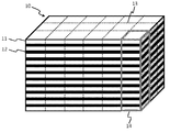
- step b the hard substrate laminate 10 is divided in the thickness direction to form a desired number of divided hard substrate laminates 14 (hereinafter referred to as “divided blocks”).
- the division in the thickness direction of the hard substrate laminate 10 can be performed, for example, along the cutting line 13 shown in FIG.
- the dividing method is not particularly limited, but a disk cutter (diamond disc, cemented carbide disc), fixed abrasive type or loose abrasive type wire saw, laser beam, etching (eg, chemical etching using hydrofluoric acid, sulfuric acid, etc.) And electrolytic etching), water jet, and red tropics (nichrome wire), each of which is used alone or in combination, and is divided into rectangular parallelepiped shapes of the same size. Etching can also be used for surface treatment of the cut surfaces after division.
- the width of the hard substrate has little variation.
- the dimensional error is preferably 100 ⁇ m or less, and more preferably 80 ⁇ m or less.
- the dimensional error is a difference between the largest width and the smallest width in one divided block that performs step c.
- the divided block is measured with a micrometer at the four corners and the central portion of the divided block. It is obtained by subtracting the smallest value from the largest value measured.
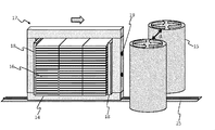
- step c the divided block 14 is relatively moved between the rotating grindstones 15 arranged in parallel at a predetermined interval to grind the two end faces 16 facing each other at the same time.
- the two end surfaces can be flattened, which contributes to an improvement in production efficiency.
- step c can also be performed on a plurality of divided blocks by stacking a plurality of divided blocks and / or arranging them side by side in the moving direction. As a result, it becomes possible to perform end face processing of a larger number of hard substrates at once.
- the difference between the width of the divided block before performing the step c and the distance d on the straight line connecting the central axes of the two rotating wheels corresponds to the width of the divided block that is reduced by one grinding process. If the width of the divided glass block before performing step c is too large compared to the distance d on the straight line connecting the central axes of the two rotating whetstones, a large load is applied during the end face processing, and the divided blocks and the rotating whetstone are damaged. Increased risk. On the other hand, if the width of the divided block before the step c is too small compared to the distance d, grinding becomes inefficient.
- the width of the divided block to be reduced by one grinding process is preferably about 10 to 300 ⁇ m, more preferably 15 to 200 ⁇ m per one end face.
- Step c can be repeated as often as necessary. From the viewpoint of effectively removing dimensional errors and chipping generated in step b without waste, it is preferable to repeat step c until the entire width is reduced by 30 to 500 ⁇ m for one end face, and the step until 50 to 300 ⁇ m is reduced. More preferably, c is repeated. The entire width of the divided block is reduced by a value twice that value.
- step c it is preferable to use a grindstone with a large surface roughness at the beginning and a grindstone with a small surface roughness for finishing.
- the end face of the divided block after grinding is flattened by using a grindstone with a small surface roughness, but the grinding efficiency of a grindstone with a small surface roughness is low. Increases the number of iterations required.
- the use frequency can be reduced by using it for finishing. Thereby, the exchange frequency of a grindstone can also be made low.
- a grindstone having a particle size of 400 or less, preferably 150 to 350, is used for the initial treatment of the repetition, and the count is increased as necessary.
- the number of 400 or more, preferably 500 to 800 is used.
- a grindstone with a grain size is used for the final treatment of the iteration. There is no need to change the count of the grindstone more than necessary, and it is usually sufficient to prepare two types for roughing and finishing.
- the count is based on JIS R 6001.
- the divided blocks 14 are arranged so that the upper and lower surfaces thereof are orthogonal to the central axes of the two rotating grindstones 15, and the divided blocks 14 are relatively moved in a direction orthogonal to the central axes of the rotating grindstones 15.
- the relative movement can be performed by moving either or both of the rotating grindstone and the divided block.
- the relative movement can be automatically performed by driving means such as a motor.
- the speed during relative movement can also be controlled by an inverter or the like.
- the rotating grindstone is produced by, for example, bonding abrasive grains with a binder.
- the material of the abrasive grains is not limited, and examples thereof include diamond and boron nitride. Diamond is preferred when grinding glass.
- the material of the binder is not limited, but includes metal bonds using metal powders, resin bonds using thermosetting resins, metal resin bonds using metal powders and thermosetting resins, etc. It is done. Among these, metal bonds are generally used in this application. Metal bonds are made by blending and sintering various materials including multiple metals. As a grindstone using a metal bond, an electrodeposited grindstone in which only one layer of diamond is embedded in the base metal by nickel plating, and an electroformed grindstone in which diamond is densely bound via plating without a base metal Is mentioned. Among these, an electroformed grindstone is preferable from the viewpoint of maintaining the shape of the grindstone.
- the material of the plating layer is not particularly limited, but generally nickel is the main component in many cases.
- the division block 14 is fixed with the jig 17 and then performed.
- the jig 17 preferably has a clamp plate 18 for sandwiching the divided block 14 in the vertical direction and / or the traveling direction.
- the clamp plate 18 can be adjusted in tightening strength by a clamp bolt 19.
- the jig 17 can also be movable on a linear rail 25 that passes through the center of the distance between the central axes of the two rotating grindstones 15 at a right angle.
- the jig 17 preferably has positioning means for placing (centering) the divided block 14 at the center between the two rotating grindstones from the viewpoint of improving dimensional accuracy.
- the positioning means is not particularly limited.
- the jig 17 is separated from the upper and lower surfaces of the divided block 14 by a distance necessary for centering in a direction perpendicular to the traveling direction.
- the butting plate 20 can be detachably attached by fixing means such as bolts 28 and 29, and this can be used as positioning means.
- the distance can be adjusted by sandwiching the spacer 21 between the main body 26 of the jig and the abutting plate 20. Centering can be completed by setting the divided block 14 to the jig 17 so that the one end surface of the divided block 14 contacts the abutting plate 20.
- the abutting plate 22 is detachably attached to the position opposite to the abutting plate 20 via a spacer 23, and bolts 28 and 29 provided in the front and rear directions are provided.
- the end face of the divided block 14 can be finely adjusted to be parallel to the traveling direction.
- the dial gauge 27 capable of measuring the tightening distance can be installed in the divided block 14 or the jig 17. After the centering is completed, the abutting plates 20 and 22 and the spacers 21 and 23 can be removed.
- the fixing of the divided block 14 to the jig is preferably performed in order to facilitate positioning by temporarily tightening loosely before performing centering and then performing final tightening after performing centering.
- step d After the step c, it is preferable to carry out a step d of polishing the ground end face.
- the end face of the hard substrate becomes smoother, the occurrence of chipping is suppressed, and the strength is remarkably improved.
- the width of the hard substrate reduced by step d is generally less than step c, typically less than 50 ⁇ m, and more typically 20-45 ⁇ m.
- the polishing method include, but are not limited to, mechanical polishing, chemical polishing, electrolytic polishing, and combinations thereof.
- a specific example of mechanical polishing is polishing with a rotating brush. At this time, the slurry containing an abrasive such as cerium oxide may be contacted with the polishing surface.
- the material of the brush is not particularly limited, and examples thereof include nylon, PVC, and PP. Pig hair, wool, horse hair, brass, cerium oxide, aluminum oxide, silicon carbide, aluminum silicate and the like can be kneaded into nylon, PVC, PP and the like.
- a specific example of chemical polishing is etching. Etching can be performed by bringing the object to be processed into contact with the etching solution by, for example, immersing it.
- the etching solution is not particularly limited, and examples thereof include hydrofluoric acid, phosphoric acid, hydrochloric acid, and ammonium salts thereof.
- Shape processing can be performed between step b and step c and / or after step c.
- an arbitrary shape processing can be performed between the step c and the step d and / or after the step d. Since processing can be performed integrally in the shape of the target plate product in the state of the divided blocks, there is an advantage that the production speed of the plate product can be significantly increased.
- Shape processing may be performed by any known means. For example, rotary grinding wheel, router, drill, outer shape processing by etching, drilling by ultrasonic vibration drill or etching, flame processing using burner, laser beam and water jet For example, a cutting process or the like.
- the shape processing is generally aimed at other than the flattening of the end face, but is not limited thereto.
- the processing methods can be used alone or in combination. Etching can also be used for surface treatment after shape processing.
- segmentation block can be peeled and a some plate-shaped product can be formed.
- the peeling method of the divided blocks may be selected according to the adhesive, but can be peeled off by heating, for example.
- the heating method in the case of a photo-curable adhesive the translucent hard substrate laminate is immersed in warm water so that the adhesive softens into a film and is well separated into each plate-like product. Is preferred.
- a suitable temperature of the hot water varies depending on the fixing agent employed, but is usually about 60 to 95 ° C., preferably 80 to 90 ° C. By irradiating light such as UV, it can be easily peeled off.
Landscapes
- Engineering & Computer Science (AREA)
- Mechanical Engineering (AREA)
- Chemical & Material Sciences (AREA)
- Ceramic Engineering (AREA)
- Inorganic Chemistry (AREA)
- Grinding And Polishing Of Tertiary Curved Surfaces And Surfaces With Complex Shapes (AREA)
- Surface Treatment Of Glass (AREA)
- Joining Of Glass To Other Materials (AREA)
- Devices For Indicating Variable Information By Combining Individual Elements (AREA)
- Laminated Bodies (AREA)
Abstract
Description
a)2枚以上の硬質基板同士が剥離可能な接着剤で貼り合わせられた硬質基板積層体を準備する工程と、
b)前記硬質基板積層体を厚み方向に分割し、所望の数の分割された硬質基板積層体(以下、「分割ブロック」という。)を形成する工程と、
c)所定の間隔で並列に配置された回転砥石の間に分割ブロックを相対移動させて分割ブロックの対向する二つの端面を同時に研削する工程と、ここで、分割ブロックの上下面はこれら回転砥石の中心軸に直交し、分割ブロックはこれら回転砥石の中心軸に直交する方向に相対移動する、
を含む硬質基板積層体の加工方法である。
a)2枚以上の硬質基板同士が剥離可能な接着剤で貼り合わせられた硬質基板積層体を準備する工程と、
b)前記硬質基板積層体を厚み方向に分割し、所望の数の分割された硬質基板積層体(以下、「分割ブロック」という。)を形成する工程と、
c)所定の間隔で並列に配置された回転砥石の間に分割ブロックを相対移動させて分割ブロックの二つの端面を同時に平坦化処理する工程と、ここで、分割ブロックの上下面はこれら回転砥石の中心軸に直交し、分割ブロックはこれら回転砥石の中心軸に直交する方向に相対移動する、
を含む。
図1を参照すると、工程aでは、2枚以上の硬質基板11同士が剥離可能な接着剤12で貼り合わせられた硬質基板積層体10を準備する。本実施形態では、硬質基板は特に制限はない。硬質基板として、透光性を有しない硬質基板を用いても良い。但し、接着剤として光硬化性接着剤を使用するときや表示素子の保護目的で使用するときは硬質基板は透光性であることが必要であり、例えば、板ガラス(強化板ガラス、素材板ガラス、透明導電膜付きガラス基板、電極や回路が形成されたガラス基板等)、サファイア基板、石英基板、プラスチック基板、フッ化マグネシウム基板などが使用可能である。本発明に使用する硬質基板としては強化ガラスが特に好ましい。強化ガラスはイオン交換法や風冷強化法などの公知の任意の方法によって製造することができる。今まで、強化ガラスを回転砥石で加工することは割れの問題が生じることから困難であったが、本発明を使用すれば強化ガラスの加工も容易にできるようになる。
重合禁止剤(E)の使用量は、(A)及び(B)の合計量100質量部に対して、0.001~3質量部が好ましく、0.01~2質量部がより好ましい。0.001質量部以上であれば、貯蔵安定性が確保されるし、3質量部以下であれば、良好な接着性が得られ、未硬化になることもない。
1.光硬化性接着剤1
以下の(A)~(E)の成分を混合して光硬化性接着剤1を作製する。
(A)多官能(メタ)アクリレートとして、日本合成社製「UV-3000B」(ポリエステル系ウレタンアクリレート、重量平均分子量18000、ポリオール化合物はポリエステルポリオール、有機ポリイソシアネート化合物はイソホロンジイソシアネート、ヒドロキシ(メタ)アクリレートは2-ヒドロキシエチルアクリレート)15質量部、ジシクロペンタニルジアクリレート(日本化薬社製「KAYARAD R-684」)15質量部、
(B)単官能(メタ)アクリレートとして、2-(1,2-シクロヘキサカルボキシイミド)エチルアクリレート(東亜合成社製「アロニックスM-140」)45質量部、フェノールエチレンオキサイド2モル変性アクリレート(東亜合成社製「アロニックスM-101A」)25質量部、
(C)光重合開始剤としてベンジルジメチルケタール(BASFジャパン社製「IRGACURE651」))10質量部、
(D)粒状物質として平均粒径100μmの球状架橋ポリスチレン粒子(アイカ工業社製「GS-100S」)1質量部、
(E)重合禁止剤として2,2-メチレン-ビス(4-メチル-6-ターシャリーブチルフェノール)(住友化学社製「スミライザーMDP-S」)0.1質量部
以下の(A)~(E)の成分を混合して光硬化性接着剤2を作製する。
(A)多官能(メタ)アクリレートとして、日本合成社製「UV-3000B」(ポリエステル系ウレタンアクリレート、重量平均分子量18000、ポリオール化合物はポリエステルポリオール、有機ポリイソシアネート化合物はイソホロンジイソシアネート、ヒドロキシ(メタ)アクリレートは2-ヒドロキシエチルアクリレート)20質量部、ジシクロペンタニルジアクリレート(日本化薬社製「KAYARAD R-684」)25質量部、
(B)単官能(メタ)アクリレートとして、2-ヒドロキシ-3-フェノキシプロピルアクリレート(東亜合成社製「アロニックスM-5700」)35質量部、フェノールエチレンオキサイド2モル変性アクリレート(東亜合成社製「アロニックスM-101A」)20質量部、
(C)光重合開始剤としてベンジルジメチルケタール(BASFジャパン社製「IRGACURE651」))10質量部、
(D)粒状物質として平均粒径100μmの球状架橋ポリスチレン粒子(アイカ工業社製「GS-100S」)1質量部、
(E)重合禁止剤として2,2-メチレン-ビス(4-メチル-6-ターシャリーブチルフェノール)(住友化学社製「スミライザーMDP-S」)0.1質量部
図2を参照すると、工程bでは、前記硬質基板積層体10を厚み方向に分割し、所望の数の分割された硬質基板積層体14(以下、「分割ブロック」という。)を形成する。前記硬質基板積層体10厚み方向への分割は例えば図2に示す切断線13に沿って行うことができる。分割方法は特に制限はないが、円板カッター(ダイヤモンドディスク、超硬合金ディスク)、固定砥粒式又は遊離砥粒式ワイヤソー、レーザービーム、エッチング(例:フッ酸や硫酸等を用いた化学エッチングや電解エッチング)、ウォータージェット及び赤熱帯(ニクロム線)をそれぞれ単独で又は組み合わせて使用して、同サイズの直方体形状に分割する方法が挙げられる。エッチングは分割後の切断面の表面処理に用いることもできる。
図3を参照すると、工程cでは、所定の間隔で並列に配置された回転砥石15の間に分割ブロック14を相対移動させて分割ブロックの対向する二つの端面16を同時に研削する。一度の加工処理で複数の硬質基板の端面を加工できることに加えて、二つの端面が平坦化できるので、生産効率の向上に寄与する。分割ブロックが直方体のときは、本工程を合計2回実施すれば、四つすべての端面を処理することもできる。更に、図3に示すように、複数の分割ブロックを積層する及び/又は移動方向に横並びすることにより、複数の分割ブロックに対してまとめて工程cを実施することもできる。これにより、更に多くの硬質基板の端面処理を一括して行うことが可能になる。
工程cの後、研削を行った端面を研磨処理する工程dを実施することが好ましい。工程dを実施することにより、硬質基板の端面がより平滑になると共に、チッピングの発生が抑制されて強度が格段に向上する。工程dによって減少する硬質基板の幅は工程cよりも少なくするのが一般的であり、典型的には50μm未満であり、より典型的には20~45μmである。研磨方法としては、限定的ではないが、機械研磨、化学研磨、電解研磨及びこれらの組み合わせが挙げられる。機械研磨の具体例として回転ブラシによる研磨が挙げられる。この時は、酸化セリウム等の研磨剤を含有したスラリーを研磨面に接触させながら行ってもよい。ブラシの材質は特に制限はないが、例えば、ナイロン、PVC、及びPPが挙げられる。豚毛、羊毛、馬毛、真鍮、酸化セリウム、酸化アルミニウム、シリコンカーバイド、及びアルミニウムシリケイト等をナイロン、PVC、及びPP等に練り込むこともできる。化学研磨の具体例としてはエッチングが挙げられる。エッチングはエッチング液に被処理物を浸漬するなどによって接触させることで実施することができる。エッチング液としては特に制限はないが、例えばフッ酸、リン酸、塩酸、及びこれらのアンモニウム塩等が挙げられる。
工程bと工程cの間、及び/又は、工程cの後に任意の形状加工を行うことができる。工程dを実施する場合は、工程cと工程dの間、及び/又は、工程dの後に、任意の形状加工を行うこともできる。分割ブロックの状態で目的とする板状製品の形状に一体的に加工を行うことができるため、板状製品の生産速度を格段に高められるという利点がある。形状加工は公知の任意の手段によって行えばよいが、例えば回転砥石、ルーター、ドリル、エッチング等による外形加工、超音波振動ドリルやエッチングによる孔開け、バーナーを用いた火炎加工、レーザービーム及びウォータージェット等による切断加工等が挙げられる。形状加工は端面の平坦化以外を目的とするのが一般的であるが、それに限定するものではない。加工方法はそれぞれ単独で又は組み合わせて使用することができる。エッチングは形状加工後の表面処理に用いることもできる。
以上のようにして硬質基板積層体の加工方法を実施した後は、分割ブロックを剥離し、複数の板状製品を形成することができる。分割ブロックの剥離方法は接着剤に応じて選択すればよいが、例えば加熱することにより剥離可能である。光硬化性接着剤の場合の加熱方法の具体例としては、固着剤がフィルム状に軟化して各板状製品に上手く分離するため、温水に形状加工後の透光性硬質基板積層体を浸漬する方法が好ましい。好適な温水の温度は採用する固着剤によって異なるが、通常は60~95℃程度、好ましくは80~90℃である。UVなどの光を照射することにより、剥離し易くすることもできる。
11 硬質基板
12 接着剤
13 切断線
14 分割された硬質基板積層体(分割ブロック)
15 回転砥石
16 端面
17 治具
18 クランプ板
19 クランプボルト
20 突き当て板
21 スペーサー
22 突き当て板
23 スペーサー
25 レール
26 治具本体
27 ダイヤルゲージ
28 ボルト
29 ボルト
Claims (12)
- a)2枚以上の硬質基板同士が剥離可能な接着剤で貼り合わせられた硬質基板積層体を準備する工程と、
b)前記硬質基板積層体を厚み方向に分割し、所望の数の分割された硬質基板積層体(以下、「分割ブロック」という。)を形成する工程と、
c)所定の間隔で並列に配置された回転砥石の間に分割ブロックを相対移動させて分割ブロックの対向する二つの端面を同時に研削する工程と、ここで、分割ブロックの上下面はこれら回転砥石の中心軸に直交し、分割ブロックはこれら回転砥石の中心軸に直交する方向に相対移動する、
を含む硬質基板積層体の加工方法。 - 工程c)は、分割ブロックを治具で固定してから行う請求項1に記載の硬質基板積層体の加工方法。
- 前記治具は、分割ブロックを二つの回転砥石の間の中央に配置させるための位置決め手段を有する請求項2に記載の硬質基板積層体の加工方法。
- 前記治具は、二つの回転砥石の中心軸間の距離の中央を直角に通過する直線状のレール上を移動可能である請求項2又は3に記載の硬質基板積層体の加工方法。
- 工程a)によって得られた硬質基板積層体において硬質基板同士を貼り合わせている接着剤は、工程b)で研削される予定の部位全体に接着剤が存在し、且つ、各硬質基板の接着面の面積の90%以上を占める請求項1~4の何れか一項に記載の硬質基板積層体の加工方法。
- 工程c)は、複数の分割ブロックを積層する及び/又は移動方向に横並びすることにより、複数の分割ブロックに対してまとめて実施する請求項1~5の何れか一項に記載の硬質基板積層体の加工方法。
- 工程c)を実施する前において、二つの回転砥石の中心軸を結ぶ方向における分割ブロックの位置精度を±100μm以内に制御する請求項1~6の何れか一項に記載の硬質基板積層体の加工方法。
- 硬質基板が強化ガラス製である請求項1~7の何れか一項に記載の硬質基板積層体の加工方法。
- 工程b)と工程c)の間、及び/又は、工程c)の後に形状加工を行う請求項1~8の何れか一項に記載の硬質基板積層体の加工方法。
- 工程c)の後に、d)研削を行った端面を研磨処理する工程を実施することを含む請求項1~8の何れか一項に記載の硬質基板積層体の加工方法。
- 工程c)と工程d)の間、及び/又は、工程d)の後に形状加工を行う請求項10に記載の硬質基板積層体の加工方法。
- 請求項1~11の何れか一項に記載の硬質基板積層体の加工方法を実施した後、分割ブロックを剥離し、複数の板状製品を形成する工程を含む板状製品の製造方法。
Priority Applications (3)
| Application Number | Priority Date | Filing Date | Title |
|---|---|---|---|
| JP2013534725A JP5956449B2 (ja) | 2011-09-22 | 2012-09-19 | 硬質基板積層体の加工方法及び板状製品の製造方法 |
| KR1020147007937A KR20140069034A (ko) | 2011-09-22 | 2012-09-19 | 경질 기판 적층체의 가공 방법 및 판형 제품의 제조 방법 |
| CN201280045897.9A CN103813995B (zh) | 2011-09-22 | 2012-09-19 | 硬质基板层叠体的加工方法及板状制品的制造方法 |
Applications Claiming Priority (2)
| Application Number | Priority Date | Filing Date | Title |
|---|---|---|---|
| JP2011-207912 | 2011-09-22 | ||
| JP2011207912 | 2011-09-22 |
Publications (1)
| Publication Number | Publication Date |
|---|---|
| WO2013042689A1 true WO2013042689A1 (ja) | 2013-03-28 |
Family
ID=47914452
Family Applications (1)
| Application Number | Title | Priority Date | Filing Date |
|---|---|---|---|
| PCT/JP2012/073946 Ceased WO2013042689A1 (ja) | 2011-09-22 | 2012-09-19 | 硬質基板積層体の加工方法及び板状製品の製造方法 |
Country Status (5)
| Country | Link |
|---|---|
| JP (1) | JP5956449B2 (ja) |
| KR (1) | KR20140069034A (ja) |
| CN (1) | CN103813995B (ja) |
| TW (1) | TWI574844B (ja) |
| WO (1) | WO2013042689A1 (ja) |
Cited By (5)
| Publication number | Priority date | Publication date | Assignee | Title |
|---|---|---|---|---|
| JP2015063413A (ja) * | 2013-09-24 | 2015-04-09 | Hoya株式会社 | 電子機器用カバーガラスのガラス基板の製造方法 |
| JP2015072453A (ja) * | 2013-09-04 | 2015-04-16 | 住友化学株式会社 | 端面加工偏光板の製造方法 |
| JP2015104785A (ja) * | 2013-11-29 | 2015-06-08 | ショーダテクトロン株式会社 | 積層ガラスブロックの保持具 |
| JP2018507158A (ja) * | 2015-02-02 | 2018-03-15 | コーニング インコーポレイテッド | 合わせガラス物品のエッジを強化する方法及びそれによって形成された合わせガラス物品 |
| KR20210111504A (ko) * | 2020-03-03 | 2021-09-13 | 에이피시스템 주식회사 | 초박 유리 처리장치 및 초박 유리 처리방법 |
Families Citing this family (10)
| Publication number | Priority date | Publication date | Assignee | Title |
|---|---|---|---|---|
| CN103435254A (zh) * | 2013-08-27 | 2013-12-11 | 江西合力泰科技股份有限公司 | 一种玻璃盖板切割工艺 |
| CN104440413B (zh) * | 2014-12-08 | 2017-04-12 | 蓝思科技股份有限公司 | 一种2.5d视窗屏异形抛光工艺及其抛光夹具 |
| KR101661278B1 (ko) * | 2015-07-14 | 2016-09-29 | 에스피텍 주식회사 | 초박형 유리의 가공방법 |
| WO2017160129A2 (ko) * | 2016-03-17 | 2017-09-21 | (주)이티에스 | 적층시트 연마방법 및 이를 수행하는 적층시트 연마장치 |
| CN106114034B (zh) * | 2016-08-23 | 2019-05-31 | 伯恩光学(深圳)有限公司 | 一种同时精雕加工多片玻璃的方法及其装置 |
| MX2020003516A (es) * | 2017-10-04 | 2020-10-28 | Saint Gobain | Cristal de vidrio compuesto que tiene un orificio pasante biselado. |
| CN112130354A (zh) * | 2020-09-16 | 2020-12-25 | 江西合力泰科技有限公司 | 一种3d眼镜产品加工工艺 |
| CN112159123B (zh) * | 2020-10-21 | 2025-04-18 | 上海匠执智能科技中心 | 一种超薄软玻璃的积累体及其制造加工方法 |
| KR102443795B1 (ko) * | 2020-11-03 | 2022-09-16 | 주식회사 도우인시스 | 초박형 글라스의 가공 방법 |
| CN114310555B (zh) * | 2022-03-08 | 2022-05-24 | 徐州朗润木业有限公司 | 一种木质板材裁切切角后打磨抛光装置 |
Citations (5)
| Publication number | Priority date | Publication date | Assignee | Title |
|---|---|---|---|---|
| JPH09323245A (ja) * | 1996-06-05 | 1997-12-16 | Matsushita Electric Ind Co Ltd | 薄板の研磨方法 |
| JPH11217232A (ja) * | 1998-01-30 | 1999-08-10 | Nippon Electric Glass Co Ltd | 電子部品用板ガラス |
| WO2008041449A1 (fr) * | 2006-10-04 | 2008-04-10 | Nippon Electric Glass Co., Ltd. | Appareil de meulage de face d'extrémité, et procédé de meulage de face d'extrémité pour substrat de verre |
| JP2009256125A (ja) * | 2008-04-15 | 2009-11-05 | Shoda Techtron Corp | 板ガラスの加工方法 |
| JP2010269389A (ja) * | 2009-05-20 | 2010-12-02 | Shoda Techtron Corp | 板ガラスの端面加工方法 |
Family Cites Families (2)
| Publication number | Priority date | Publication date | Assignee | Title |
|---|---|---|---|---|
| KR100826846B1 (ko) * | 2007-07-24 | 2008-05-02 | 주식회사 이 월드 | 적층 접합방식 박판 강화유리 제조방법 및 그러한 방법에 의한 접합로 |
| MY166265A (en) * | 2010-01-21 | 2018-06-22 | Denka Company Ltd | Method of manufacturing translucent rigid substrate laminate and translucent rigid substrate bonding apparatus |
-
2012
- 2012-09-19 WO PCT/JP2012/073946 patent/WO2013042689A1/ja not_active Ceased
- 2012-09-19 JP JP2013534725A patent/JP5956449B2/ja not_active Expired - Fee Related
- 2012-09-19 KR KR1020147007937A patent/KR20140069034A/ko not_active Withdrawn
- 2012-09-19 CN CN201280045897.9A patent/CN103813995B/zh not_active Expired - Fee Related
- 2012-09-21 TW TW101134635A patent/TWI574844B/zh active
Patent Citations (5)
| Publication number | Priority date | Publication date | Assignee | Title |
|---|---|---|---|---|
| JPH09323245A (ja) * | 1996-06-05 | 1997-12-16 | Matsushita Electric Ind Co Ltd | 薄板の研磨方法 |
| JPH11217232A (ja) * | 1998-01-30 | 1999-08-10 | Nippon Electric Glass Co Ltd | 電子部品用板ガラス |
| WO2008041449A1 (fr) * | 2006-10-04 | 2008-04-10 | Nippon Electric Glass Co., Ltd. | Appareil de meulage de face d'extrémité, et procédé de meulage de face d'extrémité pour substrat de verre |
| JP2009256125A (ja) * | 2008-04-15 | 2009-11-05 | Shoda Techtron Corp | 板ガラスの加工方法 |
| JP2010269389A (ja) * | 2009-05-20 | 2010-12-02 | Shoda Techtron Corp | 板ガラスの端面加工方法 |
Cited By (8)
| Publication number | Priority date | Publication date | Assignee | Title |
|---|---|---|---|---|
| JP2015072453A (ja) * | 2013-09-04 | 2015-04-16 | 住友化学株式会社 | 端面加工偏光板の製造方法 |
| JP2015063413A (ja) * | 2013-09-24 | 2015-04-09 | Hoya株式会社 | 電子機器用カバーガラスのガラス基板の製造方法 |
| JP2015104785A (ja) * | 2013-11-29 | 2015-06-08 | ショーダテクトロン株式会社 | 積層ガラスブロックの保持具 |
| JP2018507158A (ja) * | 2015-02-02 | 2018-03-15 | コーニング インコーポレイテッド | 合わせガラス物品のエッジを強化する方法及びそれによって形成された合わせガラス物品 |
| US10384324B2 (en) | 2015-02-02 | 2019-08-20 | Corning Incorporated | Methods for strengthening edges of laminated glass articles and laminated glass articles formed therefrom |
| US11389919B2 (en) | 2015-02-02 | 2022-07-19 | Corning Incorporated | Methods for strengthening edges of laminated glass articles and laminated glass articles formed therefrom |
| KR20210111504A (ko) * | 2020-03-03 | 2021-09-13 | 에이피시스템 주식회사 | 초박 유리 처리장치 및 초박 유리 처리방법 |
| KR102508911B1 (ko) | 2020-03-03 | 2023-03-13 | 에이피시스템 주식회사 | 초박 유리 처리장치 및 초박 유리 처리방법 |
Also Published As
| Publication number | Publication date |
|---|---|
| CN103813995B (zh) | 2016-11-09 |
| KR20140069034A (ko) | 2014-06-09 |
| JPWO2013042689A1 (ja) | 2015-03-26 |
| JP5956449B2 (ja) | 2016-07-27 |
| TWI574844B (zh) | 2017-03-21 |
| CN103813995A (zh) | 2014-05-21 |
| TW201318866A (zh) | 2013-05-16 |
Similar Documents
| Publication | Publication Date | Title |
|---|---|---|
| JP5956449B2 (ja) | 硬質基板積層体の加工方法及び板状製品の製造方法 | |
| JP5812990B2 (ja) | 透光性硬質基板積層体の製造方法 | |
| KR101696331B1 (ko) | 투광성 경질 기판 적층체의 가공 방법 및 판상 제품의 제조 방법 | |
| JP5925127B2 (ja) | 平板の貼合わせ治具及び平板積層体の製造方法 | |
| KR101824709B1 (ko) | 투광성 경질 기판 적층체의 제조방법 및 투광성 경질 기판 라미네이팅 장치 | |
| WO2011089964A1 (ja) | 透光性硬質基板積層体の製造方法及び透光性硬質基板貼り合わせ装置 | |
| TW201410423A (zh) | 積層體之加工裝置及加工方法 | |
| WO2012077645A1 (ja) | 硬質基板積層体の加工方法及び板状製品の製造方法 | |
| WO2013039231A1 (ja) | 硬質基板積層体の加工方法及びクランプ治具 | |
| JPWO2013084953A1 (ja) | 透光性硬質基板積層体の製造方法 | |
| WO2015046471A1 (ja) | 積層体およびその製造方法 | |
| JP5831887B2 (ja) | 透光性硬質基板積層体の加工方法及びこれを使用した板状製品の製造方法 | |
| WO2014192941A1 (ja) | 硬質基板積層体および硬質基板積層体の製造方法 | |
| JP5916620B2 (ja) | 透光性硬質基板積層体の剥離方法及びこれを使用した板状製品の製造方法 | |
| TWI546188B (zh) | Processing method of hard substrate laminated body | |
| WO2014192942A1 (ja) | 積層体およびその製造方法 | |
| HK1186202B (en) | Method for processing light-transmitting rigid substrate laminate and method for manufacturing plate shaped product |
Legal Events
| Date | Code | Title | Description |
|---|---|---|---|
| 121 | Ep: the epo has been informed by wipo that ep was designated in this application |
Ref document number: 12832955 Country of ref document: EP Kind code of ref document: A1 |
|
| ENP | Entry into the national phase |
Ref document number: 2013534725 Country of ref document: JP Kind code of ref document: A |
|
| NENP | Non-entry into the national phase |
Ref country code: DE |
|
| ENP | Entry into the national phase |
Ref document number: 20147007937 Country of ref document: KR Kind code of ref document: A |
|
| 122 | Ep: pct application non-entry in european phase |
Ref document number: 12832955 Country of ref document: EP Kind code of ref document: A1 |