WO2013039193A1 - 鉄損特性に優れる方向性電磁鋼板の製造方法 - Google Patents
鉄損特性に優れる方向性電磁鋼板の製造方法 Download PDFInfo
- Publication number
- WO2013039193A1 WO2013039193A1 PCT/JP2012/073608 JP2012073608W WO2013039193A1 WO 2013039193 A1 WO2013039193 A1 WO 2013039193A1 JP 2012073608 W JP2012073608 W JP 2012073608W WO 2013039193 A1 WO2013039193 A1 WO 2013039193A1
- Authority
- WO
- WIPO (PCT)
- Prior art keywords
- mass
- annealing
- steel sheet
- temperature
- primary recrystallization
- Prior art date
Links
- 229910000831 Steel Inorganic materials 0.000 title claims abstract description 52
- 239000010959 steel Substances 0.000 title claims abstract description 52
- 238000000034 method Methods 0.000 title claims abstract description 22
- 230000008569 process Effects 0.000 title claims abstract description 12
- 238000001953 recrystallisation Methods 0.000 claims abstract description 87
- 238000000137 annealing Methods 0.000 claims abstract description 85
- 238000005097 cold rolling Methods 0.000 claims abstract description 20
- 229910052717 sulfur Inorganic materials 0.000 claims abstract description 9
- 229910001224 Grain-oriented electrical steel Inorganic materials 0.000 claims description 20
- 238000004519 manufacturing process Methods 0.000 claims description 20
- 230000000630 rising effect Effects 0.000 claims description 14
- 239000000203 mixture Substances 0.000 claims description 9
- 229910052711 selenium Inorganic materials 0.000 claims description 6
- 229910052787 antimony Inorganic materials 0.000 claims description 4
- 229910052804 chromium Inorganic materials 0.000 claims description 4
- 229910052759 nickel Inorganic materials 0.000 claims description 4
- 229910052758 niobium Inorganic materials 0.000 claims description 4
- 229910052718 tin Inorganic materials 0.000 claims description 4
- 229910052797 bismuth Inorganic materials 0.000 claims description 3
- 239000012535 impurity Substances 0.000 claims description 3
- 229910052750 molybdenum Inorganic materials 0.000 claims description 3
- 229910052698 phosphorus Inorganic materials 0.000 claims description 3
- 229910000976 Electrical steel Inorganic materials 0.000 claims description 2
- 238000010438 heat treatment Methods 0.000 abstract description 35
- 238000005098 hot rolling Methods 0.000 abstract description 6
- 229910052748 manganese Inorganic materials 0.000 abstract description 4
- 229910052757 nitrogen Inorganic materials 0.000 abstract description 4
- 230000001105 regulatory effect Effects 0.000 abstract description 3
- 239000010960 cold rolled steel Substances 0.000 abstract 1
- 230000014509 gene expression Effects 0.000 abstract 1
- XEEYBQQBJWHFJM-UHFFFAOYSA-N Iron Chemical compound [Fe] XEEYBQQBJWHFJM-UHFFFAOYSA-N 0.000 description 47
- 229910052742 iron Inorganic materials 0.000 description 23
- 238000011084 recovery Methods 0.000 description 19
- 238000001556 precipitation Methods 0.000 description 16
- 238000005261 decarburization Methods 0.000 description 14
- 230000000694 effects Effects 0.000 description 14
- 239000013078 crystal Substances 0.000 description 10
- 239000000047 product Substances 0.000 description 10
- 238000012360 testing method Methods 0.000 description 8
- 239000011248 coating agent Substances 0.000 description 7
- 238000000576 coating method Methods 0.000 description 7
- 239000003112 inhibitor Substances 0.000 description 7
- 239000000835 fiber Substances 0.000 description 6
- 239000002244 precipitate Substances 0.000 description 6
- 229910052802 copper Inorganic materials 0.000 description 4
- 229910052839 forsterite Inorganic materials 0.000 description 4
- 230000006872 improvement Effects 0.000 description 4
- HCWCAKKEBCNQJP-UHFFFAOYSA-N magnesium orthosilicate Chemical compound [Mg+2].[Mg+2].[O-][Si]([O-])([O-])[O-] HCWCAKKEBCNQJP-UHFFFAOYSA-N 0.000 description 4
- 230000005381 magnetic domain Effects 0.000 description 4
- 239000006104 solid solution Substances 0.000 description 4
- 229910010413 TiO 2 Inorganic materials 0.000 description 3
- 239000000463 material Substances 0.000 description 3
- 230000001590 oxidative effect Effects 0.000 description 3
- 238000007670 refining Methods 0.000 description 3
- 238000005096 rolling process Methods 0.000 description 3
- 239000002002 slurry Substances 0.000 description 3
- 229910052719 titanium Inorganic materials 0.000 description 3
- XLYOFNOQVPJJNP-UHFFFAOYSA-N water Substances O XLYOFNOQVPJJNP-UHFFFAOYSA-N 0.000 description 3
- 229910018072 Al 2 O 3 Inorganic materials 0.000 description 2
- IJGRMHOSHXDMSA-UHFFFAOYSA-N Atomic nitrogen Chemical compound N#N IJGRMHOSHXDMSA-UHFFFAOYSA-N 0.000 description 2
- 229910019142 PO4 Inorganic materials 0.000 description 2
- YRKCREAYFQTBPV-UHFFFAOYSA-N acetylacetone Chemical compound CC(=O)CC(C)=O YRKCREAYFQTBPV-UHFFFAOYSA-N 0.000 description 2
- 230000008859 change Effects 0.000 description 2
- 230000001276 controlling effect Effects 0.000 description 2
- 238000001816 cooling Methods 0.000 description 2
- 238000002425 crystallisation Methods 0.000 description 2
- 230000008025 crystallization Effects 0.000 description 2
- 238000005516 engineering process Methods 0.000 description 2
- 150000004767 nitrides Chemical class 0.000 description 2
- 238000005121 nitriding Methods 0.000 description 2
- NBIIXXVUZAFLBC-UHFFFAOYSA-K phosphate Chemical compound [O-]P([O-])([O-])=O NBIIXXVUZAFLBC-UHFFFAOYSA-K 0.000 description 2
- 239000010452 phosphate Substances 0.000 description 2
- UFHFLCQGNIYNRP-UHFFFAOYSA-N Hydrogen Chemical compound [H][H] UFHFLCQGNIYNRP-UHFFFAOYSA-N 0.000 description 1
- 229910000565 Non-oriented electrical steel Inorganic materials 0.000 description 1
- 229910004298 SiO 2 Inorganic materials 0.000 description 1
- 230000009471 action Effects 0.000 description 1
- 230000032683 aging Effects 0.000 description 1
- QVGXLLKOCUKJST-UHFFFAOYSA-N atomic oxygen Chemical compound [O] QVGXLLKOCUKJST-UHFFFAOYSA-N 0.000 description 1
- 239000008119 colloidal silica Substances 0.000 description 1
- 239000002131 composite material Substances 0.000 description 1
- 238000007796 conventional method Methods 0.000 description 1
- 238000012937 correction Methods 0.000 description 1
- 230000007423 decrease Effects 0.000 description 1
- 230000007547 defect Effects 0.000 description 1
- 230000003111 delayed effect Effects 0.000 description 1
- 230000002542 deteriorative effect Effects 0.000 description 1
- 238000004090 dissolution Methods 0.000 description 1
- 238000005485 electric heating Methods 0.000 description 1
- 239000003792 electrolyte Substances 0.000 description 1
- 238000000866 electrolytic etching Methods 0.000 description 1
- 238000010894 electron beam technology Methods 0.000 description 1
- 238000002474 experimental method Methods 0.000 description 1
- 238000001914 filtration Methods 0.000 description 1
- 230000004907 flux Effects 0.000 description 1
- 229910052739 hydrogen Inorganic materials 0.000 description 1
- 239000001257 hydrogen Substances 0.000 description 1
- 230000001771 impaired effect Effects 0.000 description 1
- 238000009413 insulation Methods 0.000 description 1
- 230000010354 integration Effects 0.000 description 1
- 238000011835 investigation Methods 0.000 description 1
- 239000000696 magnetic material Substances 0.000 description 1
- 238000005259 measurement Methods 0.000 description 1
- 230000003647 oxidation Effects 0.000 description 1
- 238000007254 oxidation reaction Methods 0.000 description 1
- 229910052760 oxygen Inorganic materials 0.000 description 1
- 239000001301 oxygen Substances 0.000 description 1
- 230000002265 prevention Effects 0.000 description 1
- 239000002994 raw material Substances 0.000 description 1
- 230000009467 reduction Effects 0.000 description 1
- 238000011160 research Methods 0.000 description 1
- 239000000243 solution Substances 0.000 description 1
- 230000000087 stabilizing effect Effects 0.000 description 1
Images

Classifications
-
- C—CHEMISTRY; METALLURGY
- C21—METALLURGY OF IRON
- C21D—MODIFYING THE PHYSICAL STRUCTURE OF FERROUS METALS; GENERAL DEVICES FOR HEAT TREATMENT OF FERROUS OR NON-FERROUS METALS OR ALLOYS; MAKING METAL MALLEABLE, e.g. BY DECARBURISATION OR TEMPERING
- C21D8/00—Modifying the physical properties by deformation combined with, or followed by, heat treatment
- C21D8/12—Modifying the physical properties by deformation combined with, or followed by, heat treatment during manufacturing of articles with special electromagnetic properties
- C21D8/1244—Modifying the physical properties by deformation combined with, or followed by, heat treatment during manufacturing of articles with special electromagnetic properties the heat treatment(s) being of interest
- C21D8/1261—Modifying the physical properties by deformation combined with, or followed by, heat treatment during manufacturing of articles with special electromagnetic properties the heat treatment(s) being of interest following hot rolling
-
- C—CHEMISTRY; METALLURGY
- C21—METALLURGY OF IRON
- C21D—MODIFYING THE PHYSICAL STRUCTURE OF FERROUS METALS; GENERAL DEVICES FOR HEAT TREATMENT OF FERROUS OR NON-FERROUS METALS OR ALLOYS; MAKING METAL MALLEABLE, e.g. BY DECARBURISATION OR TEMPERING
- C21D8/00—Modifying the physical properties by deformation combined with, or followed by, heat treatment
- C21D8/12—Modifying the physical properties by deformation combined with, or followed by, heat treatment during manufacturing of articles with special electromagnetic properties
- C21D8/1244—Modifying the physical properties by deformation combined with, or followed by, heat treatment during manufacturing of articles with special electromagnetic properties the heat treatment(s) being of interest
- C21D8/1272—Final recrystallisation annealing
-
- C—CHEMISTRY; METALLURGY
- C22—METALLURGY; FERROUS OR NON-FERROUS ALLOYS; TREATMENT OF ALLOYS OR NON-FERROUS METALS
- C22C—ALLOYS
- C22C38/00—Ferrous alloys, e.g. steel alloys
- C22C38/001—Ferrous alloys, e.g. steel alloys containing N
-
- C—CHEMISTRY; METALLURGY
- C22—METALLURGY; FERROUS OR NON-FERROUS ALLOYS; TREATMENT OF ALLOYS OR NON-FERROUS METALS
- C22C—ALLOYS
- C22C38/00—Ferrous alloys, e.g. steel alloys
- C22C38/002—Ferrous alloys, e.g. steel alloys containing In, Mg, or other elements not provided for in one single group C22C38/001 - C22C38/60
-
- C—CHEMISTRY; METALLURGY
- C22—METALLURGY; FERROUS OR NON-FERROUS ALLOYS; TREATMENT OF ALLOYS OR NON-FERROUS METALS
- C22C—ALLOYS
- C22C38/00—Ferrous alloys, e.g. steel alloys
- C22C38/008—Ferrous alloys, e.g. steel alloys containing tin
-
- C—CHEMISTRY; METALLURGY
- C22—METALLURGY; FERROUS OR NON-FERROUS ALLOYS; TREATMENT OF ALLOYS OR NON-FERROUS METALS
- C22C—ALLOYS
- C22C38/00—Ferrous alloys, e.g. steel alloys
- C22C38/02—Ferrous alloys, e.g. steel alloys containing silicon
-
- C—CHEMISTRY; METALLURGY
- C22—METALLURGY; FERROUS OR NON-FERROUS ALLOYS; TREATMENT OF ALLOYS OR NON-FERROUS METALS
- C22C—ALLOYS
- C22C38/00—Ferrous alloys, e.g. steel alloys
- C22C38/04—Ferrous alloys, e.g. steel alloys containing manganese
-
- C—CHEMISTRY; METALLURGY
- C22—METALLURGY; FERROUS OR NON-FERROUS ALLOYS; TREATMENT OF ALLOYS OR NON-FERROUS METALS
- C22C—ALLOYS
- C22C38/00—Ferrous alloys, e.g. steel alloys
- C22C38/06—Ferrous alloys, e.g. steel alloys containing aluminium
-
- C—CHEMISTRY; METALLURGY
- C22—METALLURGY; FERROUS OR NON-FERROUS ALLOYS; TREATMENT OF ALLOYS OR NON-FERROUS METALS
- C22C—ALLOYS
- C22C38/00—Ferrous alloys, e.g. steel alloys
- C22C38/08—Ferrous alloys, e.g. steel alloys containing nickel
-
- C—CHEMISTRY; METALLURGY
- C22—METALLURGY; FERROUS OR NON-FERROUS ALLOYS; TREATMENT OF ALLOYS OR NON-FERROUS METALS
- C22C—ALLOYS
- C22C38/00—Ferrous alloys, e.g. steel alloys
- C22C38/12—Ferrous alloys, e.g. steel alloys containing tungsten, tantalum, molybdenum, vanadium, or niobium
-
- C—CHEMISTRY; METALLURGY
- C22—METALLURGY; FERROUS OR NON-FERROUS ALLOYS; TREATMENT OF ALLOYS OR NON-FERROUS METALS
- C22C—ALLOYS
- C22C38/00—Ferrous alloys, e.g. steel alloys
- C22C38/14—Ferrous alloys, e.g. steel alloys containing titanium or zirconium
-
- C—CHEMISTRY; METALLURGY
- C22—METALLURGY; FERROUS OR NON-FERROUS ALLOYS; TREATMENT OF ALLOYS OR NON-FERROUS METALS
- C22C—ALLOYS
- C22C38/00—Ferrous alloys, e.g. steel alloys
- C22C38/16—Ferrous alloys, e.g. steel alloys containing copper
-
- C—CHEMISTRY; METALLURGY
- C22—METALLURGY; FERROUS OR NON-FERROUS ALLOYS; TREATMENT OF ALLOYS OR NON-FERROUS METALS
- C22C—ALLOYS
- C22C38/00—Ferrous alloys, e.g. steel alloys
- C22C38/18—Ferrous alloys, e.g. steel alloys containing chromium
- C22C38/34—Ferrous alloys, e.g. steel alloys containing chromium with more than 1.5% by weight of silicon
-
- C—CHEMISTRY; METALLURGY
- C22—METALLURGY; FERROUS OR NON-FERROUS ALLOYS; TREATMENT OF ALLOYS OR NON-FERROUS METALS
- C22C—ALLOYS
- C22C38/00—Ferrous alloys, e.g. steel alloys
- C22C38/60—Ferrous alloys, e.g. steel alloys containing lead, selenium, tellurium, or antimony, or more than 0.04% by weight of sulfur
-
- H—ELECTRICITY
- H01—ELECTRIC ELEMENTS
- H01F—MAGNETS; INDUCTANCES; TRANSFORMERS; SELECTION OF MATERIALS FOR THEIR MAGNETIC PROPERTIES
- H01F1/00—Magnets or magnetic bodies characterised by the magnetic materials therefor; Selection of materials for their magnetic properties
- H01F1/01—Magnets or magnetic bodies characterised by the magnetic materials therefor; Selection of materials for their magnetic properties of inorganic materials
- H01F1/03—Magnets or magnetic bodies characterised by the magnetic materials therefor; Selection of materials for their magnetic properties of inorganic materials characterised by their coercivity
- H01F1/12—Magnets or magnetic bodies characterised by the magnetic materials therefor; Selection of materials for their magnetic properties of inorganic materials characterised by their coercivity of soft-magnetic materials
- H01F1/14—Magnets or magnetic bodies characterised by the magnetic materials therefor; Selection of materials for their magnetic properties of inorganic materials characterised by their coercivity of soft-magnetic materials metals or alloys
- H01F1/16—Magnets or magnetic bodies characterised by the magnetic materials therefor; Selection of materials for their magnetic properties of inorganic materials characterised by their coercivity of soft-magnetic materials metals or alloys in the form of sheets
-
- C—CHEMISTRY; METALLURGY
- C21—METALLURGY OF IRON
- C21D—MODIFYING THE PHYSICAL STRUCTURE OF FERROUS METALS; GENERAL DEVICES FOR HEAT TREATMENT OF FERROUS OR NON-FERROUS METALS OR ALLOYS; MAKING METAL MALLEABLE, e.g. BY DECARBURISATION OR TEMPERING
- C21D2201/00—Treatment for obtaining particular effects
- C21D2201/05—Grain orientation
-
- C—CHEMISTRY; METALLURGY
- C21—METALLURGY OF IRON
- C21D—MODIFYING THE PHYSICAL STRUCTURE OF FERROUS METALS; GENERAL DEVICES FOR HEAT TREATMENT OF FERROUS OR NON-FERROUS METALS OR ALLOYS; MAKING METAL MALLEABLE, e.g. BY DECARBURISATION OR TEMPERING
- C21D8/00—Modifying the physical properties by deformation combined with, or followed by, heat treatment
- C21D8/12—Modifying the physical properties by deformation combined with, or followed by, heat treatment during manufacturing of articles with special electromagnetic properties
- C21D8/1216—Modifying the physical properties by deformation combined with, or followed by, heat treatment during manufacturing of articles with special electromagnetic properties the working step(s) being of interest
- C21D8/1222—Hot rolling
-
- C—CHEMISTRY; METALLURGY
- C21—METALLURGY OF IRON
- C21D—MODIFYING THE PHYSICAL STRUCTURE OF FERROUS METALS; GENERAL DEVICES FOR HEAT TREATMENT OF FERROUS OR NON-FERROUS METALS OR ALLOYS; MAKING METAL MALLEABLE, e.g. BY DECARBURISATION OR TEMPERING
- C21D8/00—Modifying the physical properties by deformation combined with, or followed by, heat treatment
- C21D8/12—Modifying the physical properties by deformation combined with, or followed by, heat treatment during manufacturing of articles with special electromagnetic properties
- C21D8/1216—Modifying the physical properties by deformation combined with, or followed by, heat treatment during manufacturing of articles with special electromagnetic properties the working step(s) being of interest
- C21D8/1233—Cold rolling
-
- C—CHEMISTRY; METALLURGY
- C21—METALLURGY OF IRON
- C21D—MODIFYING THE PHYSICAL STRUCTURE OF FERROUS METALS; GENERAL DEVICES FOR HEAT TREATMENT OF FERROUS OR NON-FERROUS METALS OR ALLOYS; MAKING METAL MALLEABLE, e.g. BY DECARBURISATION OR TEMPERING
- C21D8/00—Modifying the physical properties by deformation combined with, or followed by, heat treatment
- C21D8/12—Modifying the physical properties by deformation combined with, or followed by, heat treatment during manufacturing of articles with special electromagnetic properties
- C21D8/1244—Modifying the physical properties by deformation combined with, or followed by, heat treatment during manufacturing of articles with special electromagnetic properties the heat treatment(s) being of interest
- C21D8/1266—Modifying the physical properties by deformation combined with, or followed by, heat treatment during manufacturing of articles with special electromagnetic properties the heat treatment(s) being of interest between cold rolling steps
Definitions
- the present invention relates to a method for producing a grain-oriented electrical steel sheet, and more specifically, to a method for producing a grain-oriented electrical steel sheet having excellent iron loss characteristics over the entire length of a product coil.
- the grain-oriented electrical steel sheet is a soft magnetic material whose crystal orientation is highly integrated in the Goss orientation ( ⁇ 110 ⁇ ⁇ 001>), and is mainly used as an iron core of a transformer.
- iron loss W 17/50 (W /) representing magnetic loss when magnetized to 1.7 T at a frequency of 50 Hz. kg is required to be low.
- the iron loss of an electromagnetic steel sheet is represented by the sum of hysteresis loss that depends on crystal orientation and purity, and eddy current loss that depends on specific resistance, plate thickness, magnetic domain size, and the like. Therefore, as a method of reducing the iron loss, a method of improving the magnetic flux density by increasing the degree of integration of crystal orientation, a method of increasing the Si content to increase the electrical resistance, a method of reducing the plate thickness of the steel plate, A method of refining next recrystallized grains or subdividing magnetic domains is known.
- Patent Document 2 discloses that the steel sheet rolled to the final plate thickness is decarburized and annealed at an atmospheric oxygen concentration of 500 ppm or less and at a heating rate of 100 ° C./second or more. Rapid heat treatment is performed at 800 to 950 ° C., the temperature of the front region of the decarburization annealing process is set to 775 to 840 ° C. lower than the reached temperature in the rapid heating, and the temperature of the subsequent rear region is higher than that of the front region 815 to It is disclosed that a grain-oriented electrical steel sheet with extremely low iron loss can be obtained by performing decarburization annealing at 875 ° C. In Patent Document 3 and Patent Document 4, a temperature range of at least 600 ° C.
- the starting temperature for rapid heating is uniquely determined, and the ultimate temperature of rapid heating is regulated to be 700 ° C. or higher, thereby improving the primary recrystallization texture and the secondary recrystallized grains. Is miniaturized.
- secondary recrystallized grains can be refined in many cases and iron loss is improved. It has been clarified that depending on the precipitation state of the precipitate, the secondary recrystallization behavior may not be stable, and the above improvement effect may not be obtained over the entire length of the coil.
- the present invention has been made in view of the above problems of the prior art, and its purpose is to refine the secondary recrystallized grains over the entire length of the product coil by stabilizing the secondary recrystallization behavior.
- Another object of the present invention is to propose an advantageous method for producing a grain-oriented electrical steel sheet capable of reducing the total length of product coils to a low iron loss.
- the inventors have various viewpoints on the influence of the precipitation state of nitrogen (N) in the steel sheet in the rapid heating temperature region uniquely defined in the prior art on the primary recrystallization behavior.
- N precipitation state of nitrogen
- the inventors can accurately achieve the refinement of secondary recrystallized grains by accurately grasping and controlling the relationship between the recovery temperature range and the recrystallization temperature range and the rate of temperature increase. I thought that it might be, and further examination.
- an optimum temperature increase rate is set for each of the recovery temperature range and the recrystallization temperature range, that is, as shown in FIG. 1, a relatively low temperature range where only recovery proceeds mainly. (Hereinafter also referred to as “low temperature range”), a high temperature increase rate is set, and a relatively high temperature range (hereinafter also referred to as “high temperature range”) where recovery and recrystallization proceed.
- low temperature range a relatively low temperature range where only recovery proceeds mainly.
- high temperature range a relatively high temperature range
- the present invention relates to C: 0.001 to 0.10 mass%, Si: 1.0 to 5.0 mass%, Mn: 0.01 to 0.5 mass%, sol. Al: 0.003 to 0.050 mass%, N: 0.0010 to 0.020 mass%, one or two selected from S and Se: total 0.005 to 0.040 mass%, the balance Is hot rolled a steel slab having a component composition consisting of Fe and unavoidable impurities, and hot-rolled sheet annealing is performed as necessary, and then cold rolling is performed once or two or more times with intermediate annealing interposed therebetween.
- NA is the amount of precipitated N (massppm) after the final cold rolling
- NB is the amount of precipitated N (massppm) after the primary recrystallization annealing.
- the method for producing a grain-oriented electrical steel sheet according to the present invention is characterized in that the total N content NB ′ (massppm) of the steel slab is used instead of the precipitated N amount NB (massppm) after the primary recrystallization annealing.
- the steel slab in the method for producing a grain-oriented electrical steel sheet according to the present invention further includes Cu: 0.01 to 0.2 mass%, Ni: 0.01 to 0.5 mass%, Cr: 0.01-0.5 mass%, Mo: 0.01-0.5 mass%, Sb: 0.01-0.1 mass%, Sn: 0.01-0.5 mass%, Bi: 0.001-0. 1 mass%, P: 0.001 to 0.05 mass%, Ti: 0.005 to 0.02 mass%, and Nb: 0.0005 to 0.0100 mass% It is characterized by.
- the secondary recrystallized grains can be stably refined over the entire length of the product coil, it becomes possible to manufacture a grain-oriented electrical steel sheet with a low yield and high yield.
- the basic technical idea of the present invention is that a relatively high temperature rise rate is set for a relatively low temperature range (low temperature range) where only recovery proceeds, and recovery and recrystallization proceed relatively.
- a description will be given of stably achieving the refinement of secondary recrystallized grains by setting a temperature rising rate lower than that in the low temperature range for the high temperature range (high temperature range).
- the primary recrystallization texture In order to optimize the secondary recrystallization behavior, it is necessary to control the primary recrystallization texture.
- the number of nuclei having Goth orientation ( ⁇ 110 ⁇ ⁇ 001>) in the primary recrystallized texture is important.
- the amount of ⁇ 111 ⁇ primary recrystallized structure that is engulfed in the Goth orientation is greatly related to the stable generation of secondary recrystallization and the prevention of growth into coarse secondary recrystallized grains.
- the core of the Goss orientation ( ⁇ 110 ⁇ ⁇ 001>) exists in a deformation band generated in the ⁇ 111 ⁇ fiber structure in which the strain energy of the rolled structure is easily accumulated.
- This deformation band is a region in which strain energy is accumulated in the ⁇ 111 ⁇ fiber structure.
- the rate of temperature rise in the low temperature region in the primary recrystallization annealing is low, the deformation band with extremely high strain energy is preferentially recovered and the strain energy is relaxed. Crystals are less likely to occur.
- the rate of temperature rise in the low temperature range is high, the deformation band can be maintained at a high temperature while the strain energy is high, so that recrystallization of Goth orientation nuclei can be preferentially caused. it can.
- the reason why the temperature rising rate is made lower than that in the low temperature region in the high temperature region following the low temperature region and the temperature rising rate is limited to a specific range will be described.
- the growth of secondary recrystallized grains (Goss orientation grains) is promoted. Even if there are many, one crystal grain may be coarsened before each grows.
- the ⁇ 111 ⁇ primary recrystallized structure is too small, secondary recrystallized grains are difficult to grow and cause secondary recrystallization failure. Therefore, it is necessary to control the ⁇ 111 ⁇ primary recrystallization structure to an appropriate amount.
- the ⁇ 111 ⁇ primary recrystallization structure is generated by recrystallization of the ⁇ 111 ⁇ fiber structure in the rolled structure.
- the primary orientation of the primary recrystallization texture is the ⁇ 111 ⁇ primary recrystallization structure unless special heat treatment or the like is performed.
- the ⁇ 111 ⁇ fiber structure has a higher strain energy than other surrounding structures, though not as much as the deformation band that generates goth-oriented nuclei. Therefore, it can be said that the crystal orientation is easy to recrystallize next to the Goth orientation under the heat treatment conditions in which the low temperature region where only recovery mainly occurs is rapidly heated.
- the recrystallization from the deformation band retaining the strain energy or the ⁇ 111 ⁇ fiber structure can be promoted by slowing the rate of temperature increase in the high temperature region.
- the nuclei in the Goss direction will increase somewhat, but the ⁇ 111 ⁇ primary recrystallized structure that becomes the main structure in nature will further increase excessively.
- the ⁇ 111 ⁇ primary recrystallized structure becomes excessive, and Goss-oriented grains become coarse in the secondary recrystallization annealing.
- the dislocation polygon in the primary recrystallization annealing since the low temperature region range and the high temperature region range are closely related to the recovery temperature and recrystallization temperature of the material, as described above, the dislocation polygon in the primary recrystallization annealing. It changes depending on the precipitation state of solid solution N, which has the effect of suppressing crystallization and delaying the recovery of the structure and the start of recrystallization, specifically, the amount of N precipitated in the primary recrystallization annealing. Therefore, it is necessary to change the rate of temperature rise according to the amount of precipitated N.
- the present invention is based on the above technical idea.
- C 0.001 to 0.10 mass%
- C is a component useful for generating goth-oriented grains, and in order to exhibit such an action, it needs to be contained in an amount of 0.001 mass% or more.
- C is set in the range of 0.001 to 0.10 mass%. Preferably, it is in the range of 0.005 to 0.08 mass%.
- Si 1.0 to 5.0 mass%
- Si has the effect of increasing the electrical resistance of the steel and reducing the iron loss.
- addition of at least 1.0 mass% is required.
- Si is set in the range of 1.0 to 5.0 mass%. Preferably, it is in the range of 2.0 to 4.5 mass%.
- Mn 0.01 to 0.5 mass% Mn not only effectively contributes to the improvement of hot brittleness of steel, but when it contains S or Se, precipitates such as MnS and MnSe are formed and function as an inhibitor. When the content of Mn is less than 0.01 mass%, the above effect is not sufficient. On the other hand, when it exceeds 0.5 mass%, the slab heating temperature necessary for dissolving precipitates such as MnS and MnSe is extremely high. It is not preferable. Therefore, Mn is in the range of 0.01 to 0.5 mass%. Preferably, it is in the range of 0.01 to 0.3 mass%.
- sol. Al 0.003 to 0.050 mass%
- Al is a useful component that forms AlN in steel and precipitates as a dispersed second phase and acts as an inhibitor.
- sol. When the content of Al is less than 0.003 mass%, a sufficient amount of precipitation cannot be secured, and the above effect cannot be obtained.
- sol. When Al is added in excess of 0.050 mass%, the slab heating temperature necessary for the dissolution of AlN becomes extremely high, and AlN becomes coarse due to the heat treatment after hot rolling, and the function as an inhibitor is lost. Therefore, Al is sol.
- the range of 0.003 to 0.050 mass% is made of Al. Preferably, it is in the range of 0.005 to 0.040 mass%.
- N 0.0010 to 0.020 mass%
- N is a component necessary to form AlN, which is an inhibitor.
- the addition amount is less than 0.0010 mass%, precipitation of AlN is insufficient.
- S and Se 0.005 to 0.040 mass% in total S and Se are useful components that combine with Mn and Cu to form MnS, MnSe, Cu 2-X S, Cu 2-X Se, precipitate as a dispersed second phase in steel, and act as an inhibitor. . If the total addition amount of these S and Se is less than 0.005 mass%, the above-described addition effect cannot be obtained sufficiently, while addition exceeding 0.040 mass% only results in incomplete solid solution during slab heating. It also causes surface defects in the product. Therefore, the addition amount of these elements is in the range of 0.005 to 0.040 mass% regardless of single addition or composite addition. Preferably, it is in the range of 0.005 to 0.030 mass%.
- the grain-oriented electrical steel sheet of the present invention further includes Cu: 0.01 to 0.2 mass%, Ni: 0.01 to 0.5 mass%, Cr: 0.01 to 0.5 mass%, Mo: 0.01 to 0.5 mass%, Sb: 0.01 to 0.1 mass%, Sn: 0.01 to 0.5 mass%, Bi: 0.001 to 0.1 mass%, P: 0.001 to One or more selected from 0.05 mass%, Ti: 0.005 to 0.02 mass%, and Nb: 0.0005 to 0.0100 mass% can be added.
- Cu, Ni, Cr, Mo, Sb, Sn, Bi, P, Ti, and Nb are elements that easily segregate at grain boundaries and surfaces, or elements that form carbonitrides, and serve as auxiliary inhibitors.
- the addition of these elements can further improve the magnetic characteristics.
- the addition amount is less than the above-described amount, the effect of suppressing the coarsening of the primary recrystallized grains cannot be sufficiently obtained in the high temperature region of the secondary recrystallization process.
- the amount exceeds the above-mentioned amount, secondary recrystallization failure and poor appearance of the film are likely to occur. Therefore, when adding these elements, it is preferable to add in the said range.
- the steel slab serving as the material of the grain-oriented electrical steel sheet according to the present invention contains N in an amount of 0.0010 mass% or more and contains a nitride-forming element such as Al that precipitates by forming a nitride. It must be a thing.
- the balance other than the components described above is Fe and inevitable impurities. However, the content of other components is not rejected as long as the effects of the present invention are not impaired.
- the method for producing a grain-oriented electrical steel sheet according to the present invention includes hot rolling a steel slab having a component composition that conforms to the present invention described above, and subjecting it to hot rolling sheet annealing as necessary, and then performing one time or intermediate annealing.
- the temperature at which the steel slab is reheated prior to hot rolling is preferably 1300 ° C. or higher because the inhibitor component must be completely dissolved.
- the hot rolling conditions, the hot-rolled sheet annealing conditions to be performed as necessary, and the cold-rolled conditions of two or more times sandwiching the intermediate annealing with the final thickness of the cold-rolled sheet are also used in a conventional manner.
- inter-pass aging or warm rolling may be employed as appropriate.
- the temperature increase rate in the low temperature range is set to 80 ° C./sec or higher, which is higher than the normal primary recrystallization annealing, and the temperature increase rate in the high temperature range is set to the temperature increase rate in the low temperature range.
- the temperature range of the low temperature region and the high temperature region in the temperature raising process is determined based on the precipitation state of N in the steel sheet.
- Solid solution N existing after cold rolling is unevenly distributed on the grain boundaries and dislocations, and nitrides are formed in the temperature rising process of the primary recrystallization annealing, resulting in fine precipitation on the dislocations, limiting the movement of dislocations.
- there is an effect of suppressing polygonization that is, delaying recovery of the rolling structure and recrystallization. Therefore, it is considered that the amount of N precipitated by the primary recrystallization annealing greatly affects recovery and recrystallization.
- the inventors measured the precipitated N amount NA (massppm) in the steel sheet after the final cold rolling and the precipitated N amount NB (massppm) in the steel sheet after the primary recrystallization annealing. Assuming that the difference (NB-NA) (massppm) is the amount of N newly precipitated by primary recrystallization annealing, this (NB-NA) and the temperature rise condition (temperature rise rate) at which good magnetic properties are obtained In order to investigate the relationship with the temperature range), many experiments were repeated. As a result, it was found that there is an appropriate temperature raising condition according to (NB-NA) as shown below.
- T1 (° C.): 500 + 2 ⁇ (NB-NA)
- Temperature T1 calculated from the following equation (2): T2 (° C.): 600 + 2 ⁇ (NB-NA) (2) It has been found that the temperature rising rate S1 between the temperature T2 and the temperature T2 obtained from the above needs to be 80 ° C./sec or more.
- the above formulas (1) and (2) indicate that when the amount of N precipitated in the primary recrystallization annealing is increased, recovery and recrystallization are delayed, so that the temperature range in the low temperature range is increased.
- the temperature rising rate S1 in this temperature range is slower than 80 ° C./sec, recovery occurs in a deformation zone where nuclei of Goss orientation ⁇ 110 ⁇ ⁇ 001> are generated, and preferential recrystallization of Goss orientation nuclei. Does not occur, and the number of Goss orientation nuclei cannot be increased, so that the secondary recrystallized grains cannot be refined.
- the temperature rising rate in this low temperature region may be increased to 80 ° C./sec or higher, the average temperature rising rate may be 80 ° C./sec or higher from a temperature lower than T1.
- the temperature increase rate S2 therebetween is the temperature increase rate S1 in the low temperature range.
- the range of 0.1 to 0.7 times is preferable.
- the lower limit temperature of the temperature range of the high temperature range is the upper limit temperature T2 of the low temperature range, and is heated to a temperature at which only a specific crystal orientation (Goss orientation) starts recrystallization by heating at the heating rate S1. Equivalent to.
- the upper limit temperature is 750 ° C., which is the temperature at which most crystals recrystallize.
- the temperature increase rate S2 in the high temperature range is related to S1 because the higher the temperature increase rate in the low temperature range, the more the recovery of the Goss orientation that is preferentially caused to recrystallize can be suppressed. Even if the residence time in the high temperature range is short, recrystallization in the Goss direction can be promoted, and the optimum temperature increase rate in the high temperature range increases accordingly in accordance with the temperature increase rate S1 in the low temperature range. It is because it is considered.
- the temperature rising rate S2 in the high temperature region is too high, the recrystallization of the structure to be preferentially recrystallized is suppressed, so that all orientations cause recrystallization and the recrystallized texture becomes In order to randomize and cause secondary recrystallization failure, it is preferable to limit the temperature raising rate of S2 to 0.7 times or less of S1. On the contrary, if the heating rate S2 in this high temperature range becomes too slow, the ⁇ 111 ⁇ primary recrystallized structure increases and the secondary grain refinement effect cannot be obtained. Is preferable. Preferred S2 is in the range of 0.2 to 0.6 times S1.
- the present invention is based on the premise that N that is unevenly distributed on dislocations introduced by cold rolling is deposited as it is on the dislocations by primary recrystallization annealing. Therefore, the present invention cannot be applied to the case where nitriding treatment is performed to increase the amount of N in steel by primary recrystallization annealing.
- primary recrystallization annealing is often performed in combination with decarburization annealing, and in the present invention, primary recrystallization annealing can also be performed as primary recrystallization annealing.
- the decarburization annealing is preferably heat-treated at a temperature increase rate suitable for the present invention in a wet hydrogen atmosphere having an atmosphere oxidation degree of PH 2 O / PH 2 of 0.1 or more.
- the decarburization annealing may be performed after the heat treatment with the temperature range and the heating rate suitable for the present invention is performed in a non-oxidizing atmosphere.
- the steel sheet subjected to primary recrystallization annealing as described above is then subjected to finish annealing for causing secondary recrystallization after appropriately applying an annealing separator to the steel sheet surface.
- an annealing separator for example, in the case of forming a forsterite film, the main component is MgO, and TiO 2 or the like is added as necessary, and when the forsterite film is not formed, A material mainly composed of SiO 2 or Al 2 O 3 can be used.
- Finished annealed steel sheet is then subjected to removal of the unreacted annealing separator on the steel sheet surface, followed by applying and baking an insulating coating on the steel sheet surface, or flattening annealing for shape correction, as necessary.
- Product plate The type of the insulating film is not particularly limited, but in order to further reduce the iron loss, it is preferable to use a tension coating that imparts a tensile tension to the surface of the steel sheet.
- JP-A-50-79442 An insulating film obtained by baking a coating solution containing phosphate-chromic acid-colloidal silica described in Japanese Patent Laid-Open No. 48-39338 or the like can be preferably used.
- annealing separator that does not form a forsterite film
- an insulating coating may be formed.
- the well-known magnetic domain subdivision in which the steel sheet after finish annealing is linearly subjected to plasma jet, laser irradiation, or electron beam irradiation, or linear distortion is imparted by a protruding roll. The treatment may be performed.
- the secondary recrystallized structure can be stably refined over the entire length of the product coil, so that a grain-oriented electrical steel sheet with low iron loss can be manufactured with a high yield. Can do.
- a steel slab containing Al: 0.03 mass%, N: 0.008 mass%, Cu: 0.2 mass%, and Sb: 0.02 mass% was heated at 1430 ° C. for 30 minutes, and then hot-rolled to obtain a sheet thickness: 2
- a 2 mm hot-rolled sheet was subjected to 1000 ° C. ⁇ 1 minute hot-rolled sheet annealing, and then cold-rolled to obtain an intermediate cold-rolled sheet having a thickness of 1.5 mm, which was subjected to intermediate annealing.
- the cooling rate is set to 30 ° C./sec to promote the precipitation of N, and after heating to 1150 ° C., the cooling rate is set to 100 ° C./sec to bring N into a solid solution state. It was performed at two levels of conditions to keep. Thereafter, cold rolling was further performed to obtain a final cold-rolled sheet having a thickness of 0.23 mm.
- a test piece of 100 mm ⁇ 300 mm was taken from the center in the longitudinal direction and the width direction of each cold-rolled coil, and was subjected to primary recrystallization annealing that served both as primary recrystallization and decarburization in the laboratory.
- the primary recrystallization annealing is performed by using an electric heating furnace and heating at various heating rates between 300 ° C. and 800 ° C. as shown in Table 1, and then holding at 840 ° C. ⁇ 2 minutes. Then decarburization was advanced. At this time, PH 2 O / PH 2 in the atmosphere was set to 0.3.
- the amount of precipitated N in the cold-rolled sheet is quantified from the residue obtained by electrolyzing, filtering, and extracting the test piece collected from the cold-rolled sheet using a 10 mass% AA electrolyte (acetylacetone). This value was defined as the precipitation N amount NA of the cold-rolled sheet.
- the amount of precipitated N was similarly determined for the steel sheet after the completion of primary recrystallization annealing, and this value was defined as the amount of precipitation N NB after primary recrystallization annealing, and the difference between NB and NA (NB-NA).
- the amount of N newly precipitated by primary recrystallization annealing was used.
- 50 pieces of the above-mentioned primary recrystallization annealed (decarburized annealed) test pieces were prepared for each heating condition, and MgO was the main component and 10 mass% of TiO 2 was added to the surface of these test pieces.
- An annealing separator was applied in a water slurry, dried and subjected to finish annealing, followed by secondary recrystallization, and then a phosphate insulating tension coating was applied and baked.
- the iron loss W 17/50 was measured with a single-plate magnetic tester for all 50 test pieces obtained under the respective heating conditions, and the average value and the standard deviation were obtained. After the iron loss measurement, the coating is pickled and removed from the test piece, the secondary recrystallized grain size in the range of 300 mm length is measured by the line segment method, the average value of 50 sheets is obtained, and the result is shown. This is also shown in 1. From this result, it can be seen that the steel sheet that has been subjected to the temperature increase of the primary recrystallization annealing under the conditions suitable for the present invention has a small secondary recrystallization grain size, good iron loss characteristics, and reduced variation.
- a product plate was obtained by applying and baking a phosphate-based insulation tension coating and flattening annealing for the purpose of flattening the steel strip.
- the precipitation N amount NA of the steel sheet after cold rolling and the precipitation N amount NB of the steel sheet after primary recrystallization were analyzed from test pieces taken from the coil length direction end and the width direction center. And asked.
- the technology of the present invention can also be applied to texture improvement of non-oriented electrical steel sheets and texture improvement of thin steel sheets.
Landscapes
- Chemical & Material Sciences (AREA)
- Engineering & Computer Science (AREA)
- Materials Engineering (AREA)
- Mechanical Engineering (AREA)
- Metallurgy (AREA)
- Organic Chemistry (AREA)
- Physics & Mathematics (AREA)
- Electromagnetism (AREA)
- Manufacturing & Machinery (AREA)
- Thermal Sciences (AREA)
- Crystallography & Structural Chemistry (AREA)
- Power Engineering (AREA)
- Dispersion Chemistry (AREA)
- Manufacturing Of Steel Electrode Plates (AREA)
- Soft Magnetic Materials (AREA)
Abstract
Description
T1(℃):500+2×(NB-NA) ・・・(1)
から求められる温度T1と、下記(2)式;
T2(℃):600+2×(NB-NA) ・・・(2)
から求められる温度T2との間の昇温速度S1を80℃/sec以上とし、かつ、温度T2~750℃の間の平均昇温速度S2を、上記S1の0.1~0.7倍とすることを特徴とする方向性電磁鋼板の製造方法である。ここで、上記(1)、(2)式中の、NAは最終冷間圧延後の析出N量(massppm)、NBは一次再結晶焼鈍後の析出N量(massppm)である。
上記ゴス方位({110}<001>)の核は、圧延組織の歪エネルギーが蓄積され易い{111}繊維組織中に生じる変形帯の中に存在することが知られている。この変形帯は、{111}繊維組織の中でも、特に歪エネルギーが蓄積された領域である。
ここで、一次再結晶焼鈍における低温度域の昇温速度が低い場合には、歪エネルギーが極めて高い変形帯が優先的に回復を起こし、歪エネルギーが緩和されてしまうため、ゴス方位核の再結晶が起こり難くなる。一方、上記低温度域の昇温速度が高い場合には、歪エネルギーが高い状態のままで変形帯を高温まで保持することができるので、ゴス方位核の再結晶を優先的に起こさせることができる。
一般に、ゴス方位({110}<001>)に蚕食され易い{111}一次再結晶組織が多過ぎると、二次再結晶粒(ゴス方位粒)の成長が促進されるため、ゴス方位の核が多数あっても、それぞれが成長する前に、1つの結晶粒が粗大化してしまうおそれがある。逆に、{111}一次再結晶組織が少な過ぎると、二次再結晶粒が成長し難くなり、二次再結晶不良を起こす。したがって、{111}一次再結晶組織は適正量に制御する必要がある。
しかし、回復と再結晶が同時に進行する比較的高い高温度域を、低温度域と同様の高い昇温速度で加熱すると、ゴス方位や、その次に再結晶しやすい{111}一次再結晶組織の再結晶が進行する前に、全ての方位の結晶も一次再結晶を開始するため、集合組織としてはランダム化する。その結果、{111}一次再結晶組織が少なくなり、二次再結晶そのものが生じなかったりする。
本発明は、上記技術思想に立脚するものである。
C:0.001~0.10mass%
Cは、ゴス方位粒を発生させるのに有用な成分であり、かかる作用を発現させるためには、0.001mass%以上の含有を必要とする。一方、Cが0.10mass%を超えると、脱炭焼鈍において脱炭不足を起こして磁気特性の低下を招くおそれがある。よって、Cは0.001~0.10mass%の範囲とする。好ましくは0.005~0.08mass%の範囲である。
Siは、鋼の電気抵抗を高めて、鉄損を低下させる効果があり、本発明では、少なくとも1.0mass%の添加を必要とする。一方、5.0mass%を超えて添加すると、冷間圧延することが困難となる。よって、Siは1.0~5.0mass%の範囲とする。好ましくは2.0~4.5mass%の範囲である。
Mnは、鋼の熱間脆性の改善に有効に寄与するだけでなく、SやSeを含有している場合には、MnSやMnSe等の析出物を形成し、インヒビタとしての機能を果たす。Mnの含有量が0.01mass%未満では、上記効果が十分ではなく、一方、0.5mass%を超える添加は、MnSやMnSe等の析出物を溶解させるのに必要なスラブ加熱温度が極めて高温となり好ましくない。よって、Mnは0.01~0.5mass%の範囲とする。好ましくは0.01~0.3mass%の範囲である。
Alは、鋼中でAlNを形成して分散第二相として析出し、インヒビタとして作用する有用成分である。しかし、sol.Alでの含有量が0.003mass%未満では、十分な析出量を確保できず、上記効果は得られない。一方、sol.Alで0.050mass%を超えて添加すると、AlNの固溶に必要なスラブ加熱温度が極めて高温になると共に、熱延以降の熱処理でAlNが粗大化し、インヒビタとしての作用が失われてしまう。よって、Alは、sol.Alで0.003~0.050mass%の範囲とする。好ましくは0.005~0.040mass%の範囲である。
Nは、Alと同様、インヒビタであるAlNを形成するために必要な成分である。しかし、添加量が0.0010mass%未満では、AlNの析出が不十分である。一方、0.020mass%を超えて添加すると、スラブ加熱時にふくれ等を生じるようになる。よって、Nは0.0010~0.020mass%の範囲とする。好ましくは0.0030~0.015mass%の範囲である。
SおよびSeは、MnやCuと結合し、MnS,MnSe,Cu2-XS,Cu2-XSeを形成して鋼中に分散第二相として析出し、インヒビタとして作用する有用成分である。これらS,Seの合計の添加量が0.005mass%未満では、上記添加効果が十分に得られず、一方、0.040mass%を超える添加は、スラブ加熱時の固溶が不完全となるだけでなく、製品の表面欠陥の原因ともなる。よって、これらの元素の添加量は、単独添加または複合添加を問わず、0.005~0.040mass%の範囲とする。好ましくは0.005~0.030mass%の範囲である。
Cu,Ni,Cr,Mo,Sb,Sn,Bi,P,TiおよびNbは、結晶粒界や表面に偏析しやすい元素、あるいは、炭窒化物を形成する元素であり、補助的なインヒビタとしての作用を有する。したがって、これらの元素を添加することで、さらなる磁気特性の改善を図ることができる。しかし、上記添加量に満たない場合には、二次再結晶過程の高温域で、一次再結晶粒の粗大化を抑制する効果が十分に得られない。一方、上記添加量を超えると、二次再結晶不良や被膜の外観不良を発生しやすくなる。よって、これらの元素を添加する場合には、上記範囲で添加するのが好ましい。
なお、上述した成分以外の残部は、Feおよび不可避的不純物である。ただし、本発明の作用効果を害しない範囲内であれば、その他の成分の含有を拒むものではない。
本発明の方向性電磁鋼板の製造方法は、上述した本発明に適合する成分組成を有する鋼スラブを熱間圧延し、必要に応じて熱延板焼鈍を施した後、1回または中間焼鈍を挟む2回以上の冷間圧延をして最終板厚の冷延板とし、一次再結晶焼鈍し、MgOやAl2O3等を主成分とする焼鈍分離剤を塗布し、仕上焼鈍する一連の工程からなるものである。
ここで、上記鋼スラブの製造方法は、本発明に適合する成分組成を満たすよう調整する必要があること以外は特に制限はなく、通常公知の製造方法を用いることができる。また、鋼スラブの熱間圧延に先立って再加熱する温度は、インヒビタ成分を完全に固溶させる必要があることから、1300℃以上とすることが好ましい。
また、熱間圧延条件、必要に応じて行う熱延板焼鈍条件、および、最終板厚の冷延板とする1回または中間焼鈍を挟む2回以上の冷間圧延条件についても、常法に準じて行えばよく、特に制限はない。なお、上記冷間圧延において、パス間時効や温間圧延を適宜採用してもよい。以下、冷間圧延以降の製造条件について説明する。
T1(℃):500+2×(NB-NA) ・・・(1)
から求められる温度T1と、下記(2)式;
T2(℃):600+2×(NB-NA) ・・・(2)
から求められる温度T2との間の昇温速度S1を80℃/sec以上とする必要があることがわかった。
また、この温度範囲の昇温速度S1が80℃/secより遅いと、ゴス方位{110}<001>の核が生成する変形帯で回復が生じてしまい、ゴス方位核の優先的な再結晶が生じず、Goss方位核の数を多くすることができないため、二次再結晶粒を微細化することができない。
なお、本発明では、この低温度域での昇温速度を80℃/sec以上に高めればよいので、T1未満の温度から平均昇温速度を80℃/sec以上としてもよい。
ここで、高温度域の温度範囲の下限温度は、低温度域の上限温度T2であり、昇温速度S1で加熱したことにより特定の結晶方位(ゴス方位)のみが再結晶を開始する温度に相当する。一方、上限温度は、殆どの結晶が再結晶してしまう温度である750℃である。
ただし、高温度域の昇温速度S2が高過ぎる場合は、優先的に再結晶させたい組織の再結晶までも抑制した状態となるため、すべての方位が再結晶を起こし、再結晶集合組織がランダム化するため、二次再結晶不良を起こすため、S2の昇温速度はS1の0.7倍以下に制限するのが好ましい。逆に、この高温度域の昇温速度S2が、遅くなり過ぎると、{111}一次再結晶組織が多くなり、二次粒の微細化効果が得られなくなるので、S1の0.1倍以上とするのが好ましい。好ましいS2は、S1の0.2~0.6倍の範囲である。
得られた各冷延コイルの長手方向、幅方向の中央部から、100mm×300mmの試験片を採取し、実験室にて、一次再結晶と脱炭を兼ねた一次再結晶焼鈍を施した。なお、上記一次再結晶焼鈍は、通電加熱炉を用いて、表1に示したように、300℃から800℃間の昇温速度を種々に変化させて加熱した後、840℃×2分間保持して脱炭を進行させた。この際、雰囲気のPH2O/PH2は0.3とした。
また、上記冷延板から採取した試験片を、10mass%のAA系電解液(アセチルアセトン)を用いて電解し、ろ過、抽出して残された残渣から、冷延板における析出N量を定量し、この値を冷延板の析出N量NAとした。また、一次再結晶焼鈍終了後の鋼板についても、同様にして析出N量を定量し、この値を一次再結晶焼鈍後の析出N量NBとし、上記NBとNAの差(NB-NA)を一次再結晶焼鈍で新たに析出したN量とした。
次いで、上記一次再結晶焼鈍(脱炭焼鈍)した試験片を、それぞれの加熱条件について各50枚ずつ作製し、これらの試験片の表面に、MgOを主成分とし、TiO2を10mass%添加した焼鈍分離剤を水スラリ状にして塗布乾燥し、仕上焼鈍を施して二次再結晶させた後、リン酸塩系の絶縁張力コーティングを塗布・焼付けた。

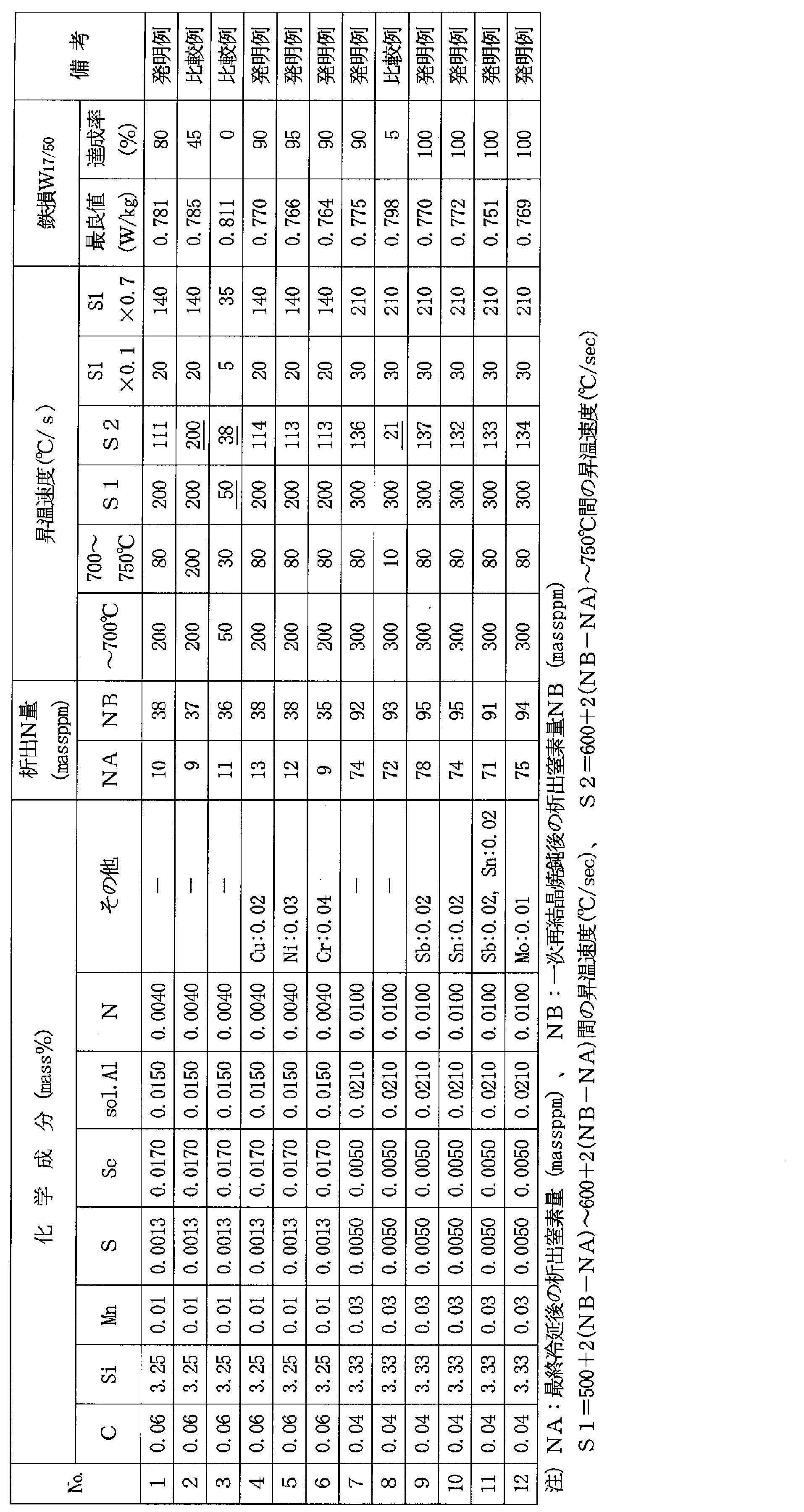
次いで、非酸化性雰囲気で、表2および表3に示す昇温速度で750℃まで加熱した後、750~840℃まで平均昇温速度:10℃/secで加熱し、その後、PH2O/PH2=0.3の雰囲気で2分間保持して脱炭する一次再結晶焼鈍を施した。次いで、上記一次再結晶後の鋼板表面に、MgOを主成分とし、TiO2を10mass%添加した焼鈍分離剤を水と混ぜてスラリ状として塗布・乾燥し、コイルに巻き取り、仕上焼鈍を施した後、リン酸塩系の絶縁張力コーティングの塗布焼付けと鋼帯の平坦化を目的とする平坦化焼鈍を施して製品板とした。
なお、この製造工程において、冷間圧延後の鋼板の析出N量NAと、一次再結晶後鋼板の析出N量NBは、コイル長さ方向端部、幅方向中央部から採取した試験片を分析して求めた。
表2から、本発明に適合する条件で加熱した発明例では、鉄損W17/50の最悪値も良好で、かつ、鉄損W17/50が0.80W/kg以下となるコイル内の比率(達成率)が高いことがわかる。

Claims (3)
- C:0.001~0.10mass%、
Si:1.0~5.0mass%、
Mn:0.01~0.5mass%、
sol.Al:0.003~0.050mass%、
N:0.0010~0.020mass%、
SおよびSeのうちから選ばれる1種または2種:合計0.005~0.040mass%を含有し、残部がFeおよび不可避的不純物からなる成分組成を有する鋼スラブを熱間圧延し、必要に応じて熱延板焼鈍を施した後、1回または中間焼鈍を挟む2回以上の冷間圧延をして最終板厚の冷延板とし、一次再結晶焼鈍し、焼鈍分離剤を塗布し、仕上焼鈍する一連の工程からなる方向性電磁鋼板の製造方法において、
上記一次再結晶焼鈍の昇温過程において、下記(1)式から求められる温度T1と、下記(2)式から求められる温度T2との間の昇温速度S1を80℃/sec以上とし、かつ、温度T2~750℃の間の平均昇温速度S2を、上記S1の0.1~0.7倍とすることを特徴とする方向性電磁鋼板の製造方法。
記
T1(℃):500+2×(NB-NA) ・・・(1)
T2(℃):600+2×(NB-NA) ・・・(2)
ここで、NA:最終冷間圧延後の析出N量(massppm)
NB:一次再結晶焼鈍後の析出N量(massppm) - 上記一次再結晶焼鈍後の析出N量NB(massppm)に代えて、鋼スラブの全N含有量NB´(massppm)を用いることを特徴とする請求項1に記載の方向性電磁鋼板の製造方法。
- 上記鋼スラブは、上記成分組成に加えてさらに、Cu:0.01~0.2mass%、Ni:0.01~0.5mass%、Cr:0.01~0.5mass%、Mo:0.01~0.5mass%、Sb:0.01~0.1mass%、Sn:0.01~0.5mass%、Bi:0.001~0.1mass%、P:0.001~0.05mass%、Ti:0.005~0.02mass%およびNb:0.0005~0.0100mass%のうちから選ばれる1種または2種以上を含有することを特徴とする請求項1または2に記載の方向性電磁鋼板の製造方法。
Priority Applications (5)
| Application Number | Priority Date | Filing Date | Title |
|---|---|---|---|
| EP12832398.7A EP2757165B1 (en) | 2011-09-16 | 2012-09-14 | Method of producing grain-oriented electrical steel sheet having excellent iron loss properties |
| US14/344,805 US20140338794A1 (en) | 2011-09-16 | 2012-09-14 | Method of producing grain-oriented electrical steel sheet having excellent iron loss properties |
| RU2014115200/02A RU2572947C2 (ru) | 2011-09-16 | 2012-09-14 | Способ изготовления листа из текстурированной электротехнической стали с превосходными свойствами потерь в железе |
| CN201280043648.6A CN103781920B (zh) | 2011-09-16 | 2012-09-14 | 铁损特性优异的取向性电磁钢板的制造方法 |
| KR1020147005984A KR101600724B1 (ko) | 2011-09-16 | 2012-09-14 | 철손 특성이 우수한 방향성 전기 강판의 제조 방법 |
Applications Claiming Priority (2)
| Application Number | Priority Date | Filing Date | Title |
|---|---|---|---|
| JP2011-203349 | 2011-09-16 | ||
| JP2011203349A JP5434999B2 (ja) | 2011-09-16 | 2011-09-16 | 鉄損特性に優れる方向性電磁鋼板の製造方法 |
Publications (1)
| Publication Number | Publication Date |
|---|---|
| WO2013039193A1 true WO2013039193A1 (ja) | 2013-03-21 |
Family
ID=47883409
Family Applications (1)
| Application Number | Title | Priority Date | Filing Date |
|---|---|---|---|
| PCT/JP2012/073608 WO2013039193A1 (ja) | 2011-09-16 | 2012-09-14 | 鉄損特性に優れる方向性電磁鋼板の製造方法 |
Country Status (7)
| Country | Link |
|---|---|
| US (1) | US20140338794A1 (ja) |
| EP (1) | EP2757165B1 (ja) |
| JP (1) | JP5434999B2 (ja) |
| KR (1) | KR101600724B1 (ja) |
| CN (1) | CN103781920B (ja) |
| RU (1) | RU2572947C2 (ja) |
| WO (1) | WO2013039193A1 (ja) |
Cited By (2)
| Publication number | Priority date | Publication date | Assignee | Title |
|---|---|---|---|---|
| EP3144399A1 (en) * | 2014-05-12 | 2017-03-22 | JFE Steel Corporation | Method for producing oriented electromagnetic steel sheet |
| EP3144400A4 (en) * | 2014-05-12 | 2017-05-17 | JFE Steel Corporation | Method for producing oriented electromagnetic steel sheet |
Families Citing this family (13)
| Publication number | Priority date | Publication date | Assignee | Title |
|---|---|---|---|---|
| JP5994981B2 (ja) * | 2011-08-12 | 2016-09-21 | Jfeスチール株式会社 | 方向性電磁鋼板の製造方法 |
| JP5360272B2 (ja) * | 2011-08-18 | 2013-12-04 | Jfeスチール株式会社 | 方向性電磁鋼板の製造方法 |
| EP2770075B1 (en) * | 2011-10-20 | 2018-02-28 | JFE Steel Corporation | Grain-oriented electrical steel sheet and method of producing the same |
| US20150243419A1 (en) * | 2012-09-27 | 2015-08-27 | Jef Steel Corporation | Method for producing grain-oriented electrical steel sheet |
| WO2016056501A1 (ja) * | 2014-10-06 | 2016-04-14 | Jfeスチール株式会社 | 低鉄損方向性電磁鋼板およびその製造方法 |
| JP6881580B2 (ja) * | 2017-07-13 | 2021-06-02 | 日本製鉄株式会社 | 方向性電磁鋼板 |
| KR102044321B1 (ko) * | 2017-12-26 | 2019-11-13 | 주식회사 포스코 | 방향성 전기강판 및 그의 제조방법 |
| JP7214974B2 (ja) * | 2018-03-30 | 2023-01-31 | 日本製鉄株式会社 | 方向性電磁鋼板の製造方法 |
| KR102164329B1 (ko) * | 2018-12-19 | 2020-10-12 | 주식회사 포스코 | 방향성의 전기강판 및 그 제조 방법 |
| CN112391512B (zh) * | 2019-08-13 | 2022-03-18 | 宝山钢铁股份有限公司 | 一种高磁感取向硅钢及其制造方法 |
| JP7463976B2 (ja) | 2020-02-28 | 2024-04-09 | Jfeスチール株式会社 | 方向性電磁鋼板の製造方法 |
| JP7364966B2 (ja) * | 2020-06-24 | 2023-10-19 | 日本製鉄株式会社 | 方向性電磁鋼板の製造方法 |
| CN111663081B (zh) * | 2020-07-10 | 2021-07-27 | 武汉科技大学 | 一种采用低温加热板坯的含铌取向硅钢及生产方法 |
Citations (10)
| Publication number | Priority date | Publication date | Assignee | Title |
|---|---|---|---|---|
| JPS4839338A (ja) | 1971-09-27 | 1973-06-09 | ||
| JPS5079442A (ja) | 1973-11-17 | 1975-06-27 | ||
| JPH0762436A (ja) | 1993-08-24 | 1995-03-07 | Nippon Steel Corp | 極めて低い鉄損をもつ一方向性電磁鋼板の製造方法 |
| JPH10298653A (ja) | 1997-04-25 | 1998-11-10 | Nippon Steel Corp | 極めて低い鉄損をもつ一方向性電磁鋼板の製造方法 |
| JP2000144249A (ja) * | 1998-11-10 | 2000-05-26 | Kawasaki Steel Corp | 被膜特性および磁気特性に優れる方向性けい素鋼板の製造方法 |
| JP2000204450A (ja) | 1999-01-14 | 2000-07-25 | Nippon Steel Corp | 皮膜特性と磁気特性に優れた方向性電磁鋼板及びその製造方法 |
| JP2000355717A (ja) * | 1999-06-15 | 2000-12-26 | Kawasaki Steel Corp | 被膜特性と磁気特性に優れた方向性けい素鋼板およびその製造方法 |
| JP2003027194A (ja) | 2001-07-12 | 2003-01-29 | Nippon Steel Corp | 皮膜特性と磁気特性に優れた方向性電磁鋼板およびその製造方法 |
| JP2008001977A (ja) * | 2006-05-24 | 2008-01-10 | Nippon Steel Corp | 方向性電磁鋼板の製造方法 |
| JP2012207278A (ja) * | 2011-03-30 | 2012-10-25 | Jfe Steel Corp | 方向性電磁鋼板の製造方法 |
Family Cites Families (9)
| Publication number | Priority date | Publication date | Assignee | Title |
|---|---|---|---|---|
| US4898626A (en) * | 1988-03-25 | 1990-02-06 | Armco Advanced Materials Corporation | Ultra-rapid heat treatment of grain oriented electrical steel |
| RU2041268C1 (ru) * | 1991-10-25 | 1995-08-09 | Армко Инк. | Способ получения высококремнистой электротехнической стали |
| DE69706388T2 (de) * | 1996-10-21 | 2002-02-14 | Kawasaki Steel Co | Kornorientiertes elektromagnetisches Stahlblech |
| KR100440994B1 (ko) * | 1996-10-21 | 2004-10-21 | 제이에프이 스틸 가부시키가이샤 | 방향성전자강판및그제조방법 |
| DE69913624T2 (de) * | 1998-09-18 | 2004-06-09 | Jfe Steel Corp. | Kornorientieres Siliziumstahlblech und Herstellungsverfahren dafür |
| US7857915B2 (en) * | 2005-06-10 | 2010-12-28 | Nippon Steel Corporation | Grain-oriented electrical steel sheet extremely excellent in magnetic properties and method of production of same |
| US7976644B2 (en) * | 2006-05-24 | 2011-07-12 | Nippon Steel Corporation | Method of production of grain-oriented electrical steel sheet with high magnetic flux density |
| JP4840518B2 (ja) * | 2010-02-24 | 2011-12-21 | Jfeスチール株式会社 | 方向性電磁鋼板の製造方法 |
| EP2770075B1 (en) * | 2011-10-20 | 2018-02-28 | JFE Steel Corporation | Grain-oriented electrical steel sheet and method of producing the same |
-
2011
- 2011-09-16 JP JP2011203349A patent/JP5434999B2/ja active Active
-
2012
- 2012-09-14 EP EP12832398.7A patent/EP2757165B1/en active Active
- 2012-09-14 KR KR1020147005984A patent/KR101600724B1/ko active IP Right Grant
- 2012-09-14 CN CN201280043648.6A patent/CN103781920B/zh active Active
- 2012-09-14 WO PCT/JP2012/073608 patent/WO2013039193A1/ja active Application Filing
- 2012-09-14 US US14/344,805 patent/US20140338794A1/en not_active Abandoned
- 2012-09-14 RU RU2014115200/02A patent/RU2572947C2/ru active
Patent Citations (10)
| Publication number | Priority date | Publication date | Assignee | Title |
|---|---|---|---|---|
| JPS4839338A (ja) | 1971-09-27 | 1973-06-09 | ||
| JPS5079442A (ja) | 1973-11-17 | 1975-06-27 | ||
| JPH0762436A (ja) | 1993-08-24 | 1995-03-07 | Nippon Steel Corp | 極めて低い鉄損をもつ一方向性電磁鋼板の製造方法 |
| JPH10298653A (ja) | 1997-04-25 | 1998-11-10 | Nippon Steel Corp | 極めて低い鉄損をもつ一方向性電磁鋼板の製造方法 |
| JP2000144249A (ja) * | 1998-11-10 | 2000-05-26 | Kawasaki Steel Corp | 被膜特性および磁気特性に優れる方向性けい素鋼板の製造方法 |
| JP2000204450A (ja) | 1999-01-14 | 2000-07-25 | Nippon Steel Corp | 皮膜特性と磁気特性に優れた方向性電磁鋼板及びその製造方法 |
| JP2000355717A (ja) * | 1999-06-15 | 2000-12-26 | Kawasaki Steel Corp | 被膜特性と磁気特性に優れた方向性けい素鋼板およびその製造方法 |
| JP2003027194A (ja) | 2001-07-12 | 2003-01-29 | Nippon Steel Corp | 皮膜特性と磁気特性に優れた方向性電磁鋼板およびその製造方法 |
| JP2008001977A (ja) * | 2006-05-24 | 2008-01-10 | Nippon Steel Corp | 方向性電磁鋼板の製造方法 |
| JP2012207278A (ja) * | 2011-03-30 | 2012-10-25 | Jfe Steel Corp | 方向性電磁鋼板の製造方法 |
Non-Patent Citations (1)
| Title |
|---|
| See also references of EP2757165A4 |
Cited By (5)
| Publication number | Priority date | Publication date | Assignee | Title |
|---|---|---|---|---|
| EP3144399A1 (en) * | 2014-05-12 | 2017-03-22 | JFE Steel Corporation | Method for producing oriented electromagnetic steel sheet |
| EP3144399A4 (en) * | 2014-05-12 | 2017-05-10 | JFE Steel Corporation | Method for producing oriented electromagnetic steel sheet |
| EP3144400A4 (en) * | 2014-05-12 | 2017-05-17 | JFE Steel Corporation | Method for producing oriented electromagnetic steel sheet |
| US10294544B2 (en) | 2014-05-12 | 2019-05-21 | Jfe Steel Corporation | Method for producing grain-oriented electrical steel sheet |
| US10294543B2 (en) | 2014-05-12 | 2019-05-21 | Jfe Steel Corporation | Method for producing grain-oriented electrical steel sheet |
Also Published As
| Publication number | Publication date |
|---|---|
| CN103781920B (zh) | 2015-05-20 |
| JP5434999B2 (ja) | 2014-03-05 |
| EP2757165B1 (en) | 2017-02-15 |
| RU2014115200A (ru) | 2015-10-27 |
| JP2013064178A (ja) | 2013-04-11 |
| EP2757165A1 (en) | 2014-07-23 |
| RU2572947C2 (ru) | 2016-01-20 |
| KR101600724B1 (ko) | 2016-03-07 |
| US20140338794A1 (en) | 2014-11-20 |
| KR20140044928A (ko) | 2014-04-15 |
| CN103781920A (zh) | 2014-05-07 |
| EP2757165A4 (en) | 2015-07-01 |
Similar Documents
| Publication | Publication Date | Title |
|---|---|---|
| JP5434999B2 (ja) | 鉄損特性に優れる方向性電磁鋼板の製造方法 | |
| JP6319605B2 (ja) | 低鉄損方向性電磁鋼板の製造方法 | |
| JP5991484B2 (ja) | 低鉄損方向性電磁鋼板の製造方法 | |
| WO2013024874A1 (ja) | 方向性電磁鋼板の製造方法 | |
| JP6132103B2 (ja) | 方向性電磁鋼板の製造方法 | |
| JP6617827B2 (ja) | 方向性電磁鋼板の製造方法 | |
| WO2014049770A1 (ja) | 方向性電磁鋼板の製造方法 | |
| JP5760590B2 (ja) | 方向性電磁鋼板の製造方法 | |
| JP2013047382A (ja) | 方向性電磁鋼板の製造方法 | |
| JP6436316B2 (ja) | 方向性電磁鋼板の製造方法 | |
| JP2012126980A (ja) | 電磁鋼板およびその製造方法 | |
| JP5287615B2 (ja) | 方向性電磁鋼板の製造方法 | |
| JP6191564B2 (ja) | 方向性電磁鋼板の製造方法および窒化処理設備 | |
| JP6056675B2 (ja) | 方向性電磁鋼板の製造方法 | |
| WO2019131853A1 (ja) | 低鉄損方向性電磁鋼板とその製造方法 | |
| JP5712652B2 (ja) | 方向性電磁鋼板の製造方法 | |
| US20230212720A1 (en) | Method for the production of high permeability grain oriented electrical steel containing chromium | |
| JP2014173103A (ja) | 方向性電磁鋼板の製造方法 | |
| JP7338511B2 (ja) | 方向性電磁鋼板の製造方法 | |
| JP4205816B2 (ja) | 磁束密度の高い一方向性電磁鋼板の製造方法 | |
| WO2022250113A1 (ja) | 方向性電磁鋼板の製造方法 | |
| WO2022210504A1 (ja) | 方向性電磁鋼板の製造方法 | |
| CN117203355A (zh) | 取向性电磁钢板的制造方法 |
Legal Events
| Date | Code | Title | Description |
|---|---|---|---|
| 121 | Ep: the epo has been informed by wipo that ep was designated in this application |
Ref document number: 12832398 Country of ref document: EP Kind code of ref document: A1 |
|
| ENP | Entry into the national phase |
Ref document number: 20147005984 Country of ref document: KR Kind code of ref document: A |
|
| REEP | Request for entry into the european phase |
Ref document number: 2012832398 Country of ref document: EP |
|
| WWE | Wipo information: entry into national phase |
Ref document number: 2012832398 Country of ref document: EP |
|
| WWE | Wipo information: entry into national phase |
Ref document number: 14344805 Country of ref document: US |
|
| NENP | Non-entry into the national phase |
Ref country code: DE |
|
| ENP | Entry into the national phase |
Ref document number: 2014115200 Country of ref document: RU Kind code of ref document: A |