WO2013021989A1 - 多心ケーブルと多心コネクタとの接続構造 - Google Patents
多心ケーブルと多心コネクタとの接続構造 Download PDFInfo
- Publication number
- WO2013021989A1 WO2013021989A1 PCT/JP2012/070054 JP2012070054W WO2013021989A1 WO 2013021989 A1 WO2013021989 A1 WO 2013021989A1 JP 2012070054 W JP2012070054 W JP 2012070054W WO 2013021989 A1 WO2013021989 A1 WO 2013021989A1
- Authority
- WO
- WIPO (PCT)
- Prior art keywords
- core
- cable
- connector
- hole
- resin coating
- Prior art date
- Legal status (The legal status is an assumption and is not a legal conclusion. Google has not performed a legal analysis and makes no representation as to the accuracy of the status listed.)
- Ceased
Links
Images




Classifications
-
- B—PERFORMING OPERATIONS; TRANSPORTING
- B29—WORKING OF PLASTICS; WORKING OF SUBSTANCES IN A PLASTIC STATE IN GENERAL
- B29C—SHAPING OR JOINING OF PLASTICS; SHAPING OF MATERIAL IN A PLASTIC STATE, NOT OTHERWISE PROVIDED FOR; AFTER-TREATMENT OF THE SHAPED PRODUCTS, e.g. REPAIRING
- B29C45/00—Injection moulding, i.e. forcing the required volume of moulding material through a nozzle into a closed mould; Apparatus therefor
- B29C45/0025—Preventing defects on the moulded article, e.g. weld lines, shrinkage marks
-
- B—PERFORMING OPERATIONS; TRANSPORTING
- B29—WORKING OF PLASTICS; WORKING OF SUBSTANCES IN A PLASTIC STATE IN GENERAL
- B29C—SHAPING OR JOINING OF PLASTICS; SHAPING OF MATERIAL IN A PLASTIC STATE, NOT OTHERWISE PROVIDED FOR; AFTER-TREATMENT OF THE SHAPED PRODUCTS, e.g. REPAIRING
- B29C45/00—Injection moulding, i.e. forcing the required volume of moulding material through a nozzle into a closed mould; Apparatus therefor
- B29C45/14—Injection moulding, i.e. forcing the required volume of moulding material through a nozzle into a closed mould; Apparatus therefor incorporating preformed parts or layers, e.g. injection moulding around inserts or for coating articles
- B29C45/14639—Injection moulding, i.e. forcing the required volume of moulding material through a nozzle into a closed mould; Apparatus therefor incorporating preformed parts or layers, e.g. injection moulding around inserts or for coating articles for obtaining an insulating effect, e.g. for electrical components
-
- B—PERFORMING OPERATIONS; TRANSPORTING
- B29—WORKING OF PLASTICS; WORKING OF SUBSTANCES IN A PLASTIC STATE IN GENERAL
- B29C—SHAPING OR JOINING OF PLASTICS; SHAPING OF MATERIAL IN A PLASTIC STATE, NOT OTHERWISE PROVIDED FOR; AFTER-TREATMENT OF THE SHAPED PRODUCTS, e.g. REPAIRING
- B29C45/00—Injection moulding, i.e. forcing the required volume of moulding material through a nozzle into a closed mould; Apparatus therefor
- B29C45/17—Component parts, details or accessories; Auxiliary operations
- B29C45/26—Moulds
- B29C45/2628—Moulds with mould parts forming holes in or through the moulded article, e.g. for bearing cages
-
- H—ELECTRICITY
- H01—ELECTRIC ELEMENTS
- H01R—ELECTRICALLY-CONDUCTIVE CONNECTIONS; STRUCTURAL ASSOCIATIONS OF A PLURALITY OF MUTUALLY-INSULATED ELECTRICAL CONNECTING ELEMENTS; COUPLING DEVICES; CURRENT COLLECTORS
- H01R43/00—Apparatus or processes specially adapted for manufacturing, assembling, maintaining, or repairing of line connectors or current collectors or for joining electric conductors
- H01R43/20—Apparatus or processes specially adapted for manufacturing, assembling, maintaining, or repairing of line connectors or current collectors or for joining electric conductors for assembling or disassembling contact members with insulating base, case or sleeve
- H01R43/24—Assembling by moulding on contact members
Definitions
- the present invention relates to a connection structure between a movable multi-core cable for a robot or the like and a multi-core connector, and a connection method thereof.
- a cable for sending power and signals to a device such as a robot needs to have flexibility in order to follow the movement of the robot, and a multi-core cable (hereinafter referred to as appropriate) to send and receive many signals.
- a multi-core cable hereinafter referred to as appropriate
- FIGS. 1 and 2 showing the embodiment of the present application (hereinafter the same)
- a large number (multi-core) of insulated core wires 3 are covered with a sheath 2.
- a multi-core connector hereinafter referred to as “connector” as appropriate
- the multi-core connector 5 is shown in FIG. 2, a plurality of holes 6 into which the terminal pieces 4 fixed to the ends of the insulating core wire 3 enter are provided.
- the connection between the multi-core cable 1 and the multi-core connector 5 is provided with terminal pieces 4 at each end of each insulated core wire 3 of the cable 1, It is carried out by being inserted into each hole 6 of the connector 5.
- the sheath 2 is peeled off at the terminal portion of the cable 1 so that the insulation core wire 3 is exposed (exposed) by a required length, and in this state, the connector 5 Connected to.
- the connecting portion between the device and the cable has conventionally been such that the end of the cable 1 (cable sheath 2) is fixed to the device with a metal fitting or the like so that no bending force is applied to the exposed insulating core wire 3 portion.
- the cable 1 is not fixed to the device with metal fittings, and the connection portion between the cable 1 and the device is made flexible (highly flexible), and ingenuity to prevent disconnection of the insulating core wire 3 is necessary.
- FIG. 1 shows that the end of the cable 1 (cable sheath 2) is fixed to the device with a metal fitting or the like so that no bending force is applied to the exposed insulating core wire 3 portion.
- each hole 6 of the connector 5 has a gap between the terminals 6 and 4 when the terminal piece 4 is inserted, so that each hole 6 is completely closed.
- the molten resin leaks to the connection side opening (the left opening 5a in FIG. 2) of the connector 5 through the hole 6 and the gap. If it leaks out, there is a risk of connection failure of the connector 5.
- a nest is inserted (inserted) into the connector 5 from the connection-side opening 5a of the connector 5, and the gap and the hole 6 are closed with the nest.
- the outer diameter tolerance of the multi-core cable 1 is large (for example, ⁇ 0.1 mm)
- the resin coating 8 is molded, if the clearance of the cable clamp portion of the mold is reduced, the cable sheath 2 is removed.
- the clamp portion is easy to bite, and if it is bitten, the cable 1 (sheath 2) is damaged, resulting in a defective product or an insulation failure.
- the clearance is increased, resin leakage from the clamp portion is caused and burrs are generated.
- Resin leakage can be prevented by stuffing an adhesive or a metal molding filling into the gap between the insert and each hole 6, the hole 6 itself, or the gap between the cable 1 and the mold clearance portion. Work is cumbersome and workability is deteriorated (preventing automation).
- the present invention allows the coating resin to enter the terminal piece holes 6 and the gaps, and the gaps between the cable 1 and the mold clearance without using inserts or filling.
- the problem is to prevent it.
- the present invention provides an exposed multi-core insulating core wire 3 with a resin having a property of not leaking from a hole in which no terminal piece is inserted before the resin coating 8 is formed.
- the multi-core connector 5 and the cable sheath 2 end are covered including the periphery, and the resin coating 8 is further formed thereon. That is, when the melting temperature (melt viscosity) of the molten resin is adjusted, it is found that the molten resin does not leak from the terminal piece hole 6 with its surface tension. It was decided to specify the size and the resin melting temperature.
- the ratio (S1 / S2) of the total area S1 of the hole 6 to the wall area S2 of the hole 6 is 0.5 to 20, and the melt viscosity of the coating resin is 0.5 to 200 Pa ⁇ s. It was. Details of S1 and S2 will be described in the following embodiment.
- the molten resin does not leak from the terminal piece hole 6 or the gap due to the surface tension of the molten resin due to the difference between the melt viscosity of the molding material and the area of the hole and the area around it, It does not enter the gap between the cable 1 and the mold clearance.
- the resin coating covering the multi-core connector and the cable sheath terminal including the periphery of the exposed multi-core insulation core wire has the outer shape of the mold cavity without causing a large sink on the surface of the mold. . If the outer shape of this resin coating becomes the required shape, the resin coating formed on the resin coating will not have a large sink on the surface, and will not become a defective product as the outer shape of the mold cavity.
- the area of the hole 6 is 4 mm 2 or less, and the total area S 2 is 120 mm 2 or less. Note that even if there is a gap between the two pieces 4 and 6 in which the terminal piece 4 is inserted into the hole 6, the gap is much smaller than the hole 6. In addition, there is no leakage from the gap. Similarly, since the clearance (gap) between the cable clamp portion and the cable is much smaller than the hole 6, there is no leakage from the gap.
- a multi-core cable having a large number of insulated core wires is inserted into the holes by inserting the terminal pieces connected to the ends of the insulated core wires.
- a connection structure between a multi-core cable and a multi-core connector a multi-core insulated core wire is exposed between the end of the cable sheath and the multi-core connector, and around the exposed multi-core insulated core wire.
- a resin coating is formed over the multi-core connector and the cable sheath terminal, and the space between the multi-core connector and the cable sheath terminal is blocked, and the resin is further applied over the multi-core connector and the cable sheath terminal via the resin coating.
- a coating is formed, and the ratio (S1 / S2) of the total area (S2) of the holes to the wall area (S1) of the holes is 0.5 to 20, and the melt viscosity of the first resin coating is 0.5 to 200 Pa ⁇ s It is possible to adopt the formation.
- a multi-core connector including the periphery of a multi-core insulated core wire exposed between the end of the cable sheath and the multi-core connector
- a resin coating is formed over the cable sheath terminal to close the gap between the multi-core connector and the cable sheath terminal, and a resin coating is further formed over the multi-core connector and the cable sheath terminal via the resin coating.
- the ratio (S1 / S2) of the total area (S2) of the holes to the wall area (S1) of the holes is 0.5 to 20, and the melt viscosity of the first resin coating is 0.5 to 200 Pa ⁇
- a configuration with s can be employed.
- the ratio (S1 / S2) is preferably 1 to 20 and the melt viscosity is 1 to 100 Pa ⁇ s.
- thermoplastic resin such as a polyester resin and an adhesive resin and the compound thereof, a polyamide resin and an adhesive resin and the compound thereof, a polyolefin resin and an adhesive Resin and its compound, urethane resin and adhesive resin and its compound, soft vinyl chloride resin and adhesive resin and its compound, vinyl acetate resin and adhesive resin and its compound, ethylene propylene resin Adhesive resins and their compounds, polyester-based liquid crystal polymers and their compounds, etc.
- adhesive resins thermoplastic polyester-based adhesive resins such as Aronmelt manufactured by Muromachi Technos, Asahi Tak Chemical Co., Ltd. Examples thereof include thermoplastic rubber-based adhesive resins.
- the terminal pieces 4 of the insulation core wire 3 are inserted into all the terminal piece holes 6 and any of the insertion holes has a gap. Even if the gap does not occur, there may be a hole in which the terminal piece is not inserted, or there is a hole in the hole in which the terminal piece is inserted and there is a hole 6 that is not inserted. is there.
- the multi-core of the multi-core cable means a case having three or more insulated core wires, and the flexible multi-core cable has the flexibility required to be connected to a moving device such as a robot. If necessary, for example, twist the insulation core wires to make a pair, twist the insulation cores, and press and wrap them with tape, place the insulation wires around them and wind them with tape.
- the outer periphery is covered with a sheath (25 AWG (0.2 mm 2 ) ⁇ 7P + 22 AWG (0.35 mm 2 ) ⁇ 6C) heat resistant vinyl insulated heat resistant oil resistant vinyl sheath composite cable, or similar (25 AWG ⁇ 6P + 25 AWG ⁇ 6C + 22 AWG ⁇ 6C) heat-resistant vinyl insulation heat-resistant oil-resistant vinyl sheathed cable or the like is used.
- a sheath 25 AWG (0.2 mm 2 ) ⁇ 7P + 22 AWG (0.35 mm 2 ) ⁇ 6C
- a sheath 25 AWG ⁇ 6P + 25 AWG ⁇ 6C + 22 AWG ⁇ 6C
- the present invention has specified the size ratio of the hole for the terminal piece of the multi-core connector and the property of the coating resin, so that the molten resin for the coating leaks out of the hole and the gap by its surface tension.
- the outer shape of the resin coating does not cause large sink marks and the outer shape of the mold cavity is obtained, and further formed on the resin coating.
- the resin coating does not cause large sink marks on its surface, and has a good transferability with an outer shape that matches the mold cavity.
- Action diagram Action diagram Action diagram The mold for a resin leak test is shown, (a) is a plan view of a lower half mold, (b) is a cut front view, and (c) is a partial external perspective view of a mold cavity. It is the principal part dimension drawing of the metal mold
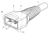
- FIGS. 1 to 4 show an embodiment of the present invention.
- a multi-core cable 1 in which 20 insulated core wires 3 are twisted and the twisted multi-core insulated core wires 3 are covered with a sheath 2 is shown.
- the cable sheath 2 is stripped to a required length, and each insulation core 3 is connected to the cable as shown in FIGS.
- the required length is exposed (exposed), and terminal pieces 4 are provided (crimped) on the exposed ends of the insulated wires 3, and the terminal pieces 4 are inserted into the holes 6 of the multi-core connector 5.
- the hole 6 is a square hole of height: 2.5 mm ⁇ width: 1.5 mm.
- the multi-fiber connector 5 with the cable 1 is loaded into a mold, and resin 9 (polyester adhesive resin, melting temperature: about 230 ° C., shear rate: about 15000 S ⁇ 1 (1 / s )) was injected at an injection pressure of 0.1 MPa to obtain a multi-fiber connector 5 with cable shown in FIG.
- resin 9 polyester adhesive resin, melting temperature: about 230 ° C., shear rate: about 15000 S ⁇ 1 (1 / s )
- the hole 7 was closed by inserting a protruding piece of a mold from the connection side opening side of the connector 5 or attaching a tetrafluororesin tape or the like.
- the mold 10 has the dimensions (unit: mm) shown in FIGS. 5A and 5B, and as shown in FIG. 5C, the cavity 11 includes a flat cavity portion 11a having a thickness of 1 mm, A substantially pyramidal cavity 11b having a cylindrical shape with its tip gradually increased from the end of the cavity 11a, and a cylindrical pool void that communicates from the pyramidal cavity 11b through a through hole 11c. 11d and divided in the middle of the top and bottom.
- 12 is a gate (molten resin injection port).
- the total area of the terminal piece holes 6 of the connector 5 can be considered as S ⁇ b> 2 in the cavity 11, and the wall area having the holes 6 can be considered as S ⁇ b> 1 in the cavity 11.
- the ratio (S1 / S2) of the total area S1 of the hole 11c to the wall area S2 of the hole 11c is 0.5 to 20.0, and the melt viscosity of the resin coating is 0.5 to 200 Pa ⁇ If s, ⁇ or ⁇ is obtained in “Resin leakage” in Table 2, and ⁇ or ⁇ is obtained in “Transferability”, there is no leakage of molten resin from the hole 11c. Understandable. Further, in the case of S1 / S2: 1.0 to 20.0 and melt viscosity: 0.5 to 100 Pa ⁇ s, all of “resin leakage” and “transferability” are excellent and excellent.
- the resin coating 9 is made of polyester.
- -Based resin copolymer melt temperature: about 230 ° C., shear rate: about 15000 s ⁇ 1 , melt viscosity: about 100 Pa ⁇ s, injection pressure: 0.1 MPa, the molten resin does not leak from the holes 6,
- the connector 1 with cable 1 of FIG. 3 having excellent transferability was obtained. From this, it can be seen that the area of the hole 6 is preferably 4 mm 2 or less and the total area S1: 120 (4 ⁇ 30) mm 2 or less.
- the cable 1 is not limited to 20 cores and 30 cores, and all the insulated core wires 3 may be connected to the connector 5 (all the terminal pieces 4 are inserted into all the holes 6). However, depending on the specifications, only the necessary insulation core wire 3 may be connected to the connector 5.
- the resin coating 9 is applied to the entire outer peripheral surface of the multi-core connector 5. However, the resin coating 9 may be applied while leaving a part of the outer peripheral surface of the multi-fiber connector 5. Although it is the case of the core connector 5, it goes without saying that the present invention can be adopted even in the case of the male multi-fiber connector 5 'shown in FIG.
- the present invention can be applied to a cable other than a cable having high flexibility (flexibility) such as a robot cable.
- a cable having high flexibility specifically, a twisted bone by the following evaluation method is used.
- the measured value of the upper hardness is 80 or less, and the difference between the measured value of the hardness on the twisted bone and the measured value of the hardness of the intermediate portion of the twisted bone and the twisted bone can be 5 or more.
- "Evaluation methods” Using the durometer hardness test type A specified in JIS K6253, place the cable on a horizontal iron table and set it so that the tip of the push needle comes over the twisted bone of the insulated wire inside the cable.
- the number of tests is an average value of 5 times each.
Landscapes
- Engineering & Computer Science (AREA)
- Manufacturing & Machinery (AREA)
- Mechanical Engineering (AREA)
- Connector Housings Or Holding Contact Members (AREA)
Abstract
多心コネクタの端子片用孔(6)への樹脂被覆(9)の入り込みを防止する。多心コネクタ(5)に端子片(4)を差込んだ、多心ケーブルと多心コネクタとの接続構造である。多心コネクタ(5)は、端子片(4)が嵌入された孔(6)に空隙を有する、又は端子片(4)が嵌入されていない孔(6)を有するものであり、孔(6)の全体面積(S1)とその孔(6)の壁面積(S2)の比(S2/S1)を0.5~20とし、樹脂被覆(9)の溶融粘度を、0.5~200Pa・sとする。このようにすれば、溶融樹脂(9)は、成型材料の溶融粘度と孔面積とその周りの面積の差による表面張力によって、端子片用孔(6)及び空隙から漏れ出ることなく、樹脂被覆(9)の表面に大きなひけ等が生じず、金型キャビティ通りの外形となった、転写性の良い樹脂被覆(9)が形成される。このため、その樹脂被覆(9)の上に形成する樹脂被覆(8)も転写性の良いものとなる。
Description
この発明は、ロボット等の可動用多心ケーブルと多心コネクタとの接続構造及びその接続方法に関するものである。
例えば、ロボット等の機器に動力や信号を送るためのケーブルは、ロボットの動きに追従するために柔軟性を有する必要があり、また、多くの信号を送受信するために多心ケーブル(以下、適宜に「ケーブル」と称する。)が使用される。このケーブルは、本願の実施形態を示す図1、2を参照して説明すると(以下、同じ)、同図に示すように、多数本(多心)の絶縁心線3をシース2によって被覆したものである(特許文献1)。
このケーブル1とロボット等の機器との接続には、通常、多心コネクタ(以下、適宜に「コネクタ」と称する。)が使用され(特許文献2)、その多心コネクタ5は、同図1、2に示すように、上記絶縁心線3の端末に固定した端子片4が入り込む多数の孔6を有するものである。
このケーブル1とロボット等の機器との接続には、通常、多心コネクタ(以下、適宜に「コネクタ」と称する。)が使用され(特許文献2)、その多心コネクタ5は、同図1、2に示すように、上記絶縁心線3の端末に固定した端子片4が入り込む多数の孔6を有するものである。
この多心ケーブル1と多心コネクタ5との接続は、同図1、2に示すように、ケーブル1の各絶縁心線3の各端末に端子片4をそれぞれ設け、その各端子片4をコネクタ5の各孔6に差込んで行われる。
このとき、同図1、2から理解できるように、ケーブル1の端末部は、シース2が剥ぎ取られて絶縁心線3が所要長さだけ露出し(剥き出され)、その状態でコネクタ5に接続される。
このとき、同図1、2から理解できるように、ケーブル1の端末部は、シース2が剥ぎ取られて絶縁心線3が所要長さだけ露出し(剥き出され)、その状態でコネクタ5に接続される。
一方、この機器とケーブルとの接続部は、従来、金具等によってケーブル1(ケーブルシース2)端末が機器に固定されて、上記剥き出し絶縁心線3部分には屈曲力がかからないようにしていた。しかし、固定すると、機器の動きに抗力が生じたり、少なからず、その剥き出し絶縁心線3の部分にも屈曲力がかかったりして、その屈曲による絶縁心線3の断線を生じる場合があった。
このため、金具等によってケーブル1を機器に固定することなく、そのケーブル1と機器との接続部をフレキシブル(柔軟性の高いもの)にするとともに、絶縁心線3の断線を防止する工夫が必要となり、通常、同図4に示すように、その露出部分を含めてケーブルシース2の端末とコネクタ5を包んで樹脂被覆8を形成したケーブル1とコネクタ5との接続構造とされている。このとき、絶縁心線3とシース2等にも当然に柔軟性を要求される。
このため、金具等によってケーブル1を機器に固定することなく、そのケーブル1と機器との接続部をフレキシブル(柔軟性の高いもの)にするとともに、絶縁心線3の断線を防止する工夫が必要となり、通常、同図4に示すように、その露出部分を含めてケーブルシース2の端末とコネクタ5を包んで樹脂被覆8を形成したケーブル1とコネクタ5との接続構造とされている。このとき、絶縁心線3とシース2等にも当然に柔軟性を要求される。
その樹脂被覆8を形成する際、コネクタ5の各孔6は端子片4が嵌入されると、両者6、4の間に隙間があったり無かったりするため、各孔6が完全に塞がっていたり、一部に隙間があったりし、また、各孔6に全ての端子片4が嵌入(接続)されるわけでもなく、そのいくらかの孔6はそのままであったり(端子片6が嵌入されなかったり)して、その孔6、隙間を介して溶融樹脂がコネクタ5の接続側開口(同図2の左側開口5a)側に漏れ出る場合が多い。漏れ出れば、コネクタ5の接続不良を招く恐れがある。
これらの恐れを無くすため、従来では、コネクタ5の接続側開口5a等からコネクタ5内に入れ子を入れ(嵌入し)、その入れ子でもって上記隙間や孔6を塞ぐようにしている。
これらの恐れを無くすため、従来では、コネクタ5の接続側開口5a等からコネクタ5内に入れ子を入れ(嵌入し)、その入れ子でもって上記隙間や孔6を塞ぐようにしている。
しかし、コネクタ5内面及び各孔6と入れ子とのクリアランスは極めて小さく、その入れ子の嵌入が煩わしく、作業性が悪くなる(自動化の妨げとなる)。一方、作業性を良くするために、そのクリアランスを大きく取れば、そのクリアランスから溶融樹脂が漏れだし、バリの要因となる。
また、多心ケーブル1は、その外径寸法公差が大きい(例えば、±0.1mm)ため、上記樹脂被覆8の成形の際、金型のケーブルクランプ部のクリアランスを小さくすると、ケーブルシース2をそのクランプ部で噛み込み易く、噛み込めば、ケーブル1(シース2)を傷付けることとなって、不良品となったり、絶縁不良を招いたりする。一方、そのクリアランスを大きくすれば、そのクランプ部からの樹脂漏れを招いてバリが生じる。
上記入れ子と各孔6との隙間や孔6それ自体、ケーブル1と金型クリアランス部の隙間に、接着剤や金属製成形詰め物等を詰め込むことによって樹脂漏れを防ぐことはできるが、それらの詰め作業は煩わしく、作業性が悪くなる(自動化の妨げとなる)。
この発明は、上記の実状に鑑み、入れ子を使用したり、詰め物をしたりすることなく、上記端子片用孔6や空隙、及びケーブル1と金型クリアランス部の隙間への被覆樹脂の入り込みを防止することを課題とする。
上記課題を達成するために、この発明は、上記樹脂被覆8を形成する前に、端子片が嵌入されていない孔から漏れ出ない性状の樹脂でもって、露出した多心の絶縁心線3の周りを含めて多心コネクタ5とケーブルシース2端末とに亘って被覆し、その上にさらに前記樹脂被覆8を形成することとしたのである。
すなわち、溶融樹脂は、その溶融温度(溶融粘度)を調整すれば、自身の表面張力でもって、上記端子片用孔6から漏れ出ることがないことを発見し、その漏れが生じない孔6の大きさ、及び樹脂溶融温度を特定することとしたのである。具体的には、上記孔6の全体面積S1とその孔6の壁面積S2の比(S1/S2)を、0.5~20とし、被覆樹脂の溶融粘度を0.5~200Pa・sとしたのである。そのS1、S2の詳細については、下記実施形態に示す。
すなわち、溶融樹脂は、その溶融温度(溶融粘度)を調整すれば、自身の表面張力でもって、上記端子片用孔6から漏れ出ることがないことを発見し、その漏れが生じない孔6の大きさ、及び樹脂溶融温度を特定することとしたのである。具体的には、上記孔6の全体面積S1とその孔6の壁面積S2の比(S1/S2)を、0.5~20とし、被覆樹脂の溶融粘度を0.5~200Pa・sとしたのである。そのS1、S2の詳細については、下記実施形態に示す。
このようにすれば、成型材料の溶融粘度と孔の面積とその周りの面積の差による溶融樹脂の表面張力によって、その溶融樹脂が端子片用孔6や空隙から漏れ出ることがなく、また、ケーブル1と金型クリアランス部の隙間へ入り込むこともない。このため、露出した多心の絶縁心線の周りを含めて多心コネクタとケーブルシース端末とに亘る樹脂被覆はその金型の表面に大きなひけ等が生じることなく金型キャビティ通りの外形となる。この樹脂被覆の外形が所要の形状となれば、その樹脂被覆の上に形成する樹脂被覆もその表面に大きなひけ等が生じることなく金型キャビティ通りの外形となって不良品となったりせず、すなわち、転写性の良好な樹脂被覆を得ることができる。
このとき、現実のコネクタ5の大きさを考慮すると、上記孔6の面積:4mm2以下、その総和面積S2:120mm2以下とする。
なお、孔6に端子片4が嵌入された両者4、6の間に隙間があっても、その間隙は、孔6より遙かに小さいため、孔6から溶融樹脂が漏れ出なければ、当然に、その間隙からも漏れでない。ケーブルクランプ部とケーブルのクリアランス(隙間)も、同様に、孔6より遙かに小さいため、その間隙から漏れでることはない。
このとき、現実のコネクタ5の大きさを考慮すると、上記孔6の面積:4mm2以下、その総和面積S2:120mm2以下とする。
なお、孔6に端子片4が嵌入された両者4、6の間に隙間があっても、その間隙は、孔6より遙かに小さいため、孔6から溶融樹脂が漏れ出なければ、当然に、その間隙からも漏れでない。ケーブルクランプ部とケーブルのクリアランス(隙間)も、同様に、孔6より遙かに小さいため、その間隙から漏れでることはない。
この発明の、多数の端子片用孔を有する多心コネクタに、多数の絶縁心線を有する多心ケーブルをその絶縁心線の端末に接続された前記端子片を差込んで前記孔に嵌入した多心ケーブルと多心コネクタとの接続構造としては、ケーブルシースの端末と多心コネクタとの間には多心の絶縁心線が露出して、その露出した多心の絶縁心線の周りを含めて多心コネクタとケーブルシース端末とに亘って樹脂被覆が形成されて多心コネクタとケーブルシース端末の間が閉塞され、その樹脂被覆を介し多心コネクタとケーブルシース端末とに亘ってさらに樹脂被覆が形成されており、かつ、前記孔の全体面積(S2)とその孔の壁面積(S1)の比(S1/S2)を0.5~20とし、前記最初の樹脂被覆の溶融粘度を0.5~200Pa・sとした構成を採用することができる。
また、この発明の上記多心ケーブルと多心コネクタとの接続構造をなす方法としては、ケーブルシースの端末と多心コネクタの間に露出した多心の絶縁心線の周りを含めて多心コネクタとケーブルシース端末とに亘って樹脂被覆を形成して多心コネクタとケーブルシース端末との間を閉塞し、その樹脂被覆を介し多心コネクタとケーブルシース端末とに亘ってさらに樹脂被覆を形成し、かつ、前記孔の全体面積(S2)とその孔の壁面積(S1)の比(S1/S2)を0.5~20とし、前記最初の樹脂被覆の溶融粘度を0.5~200Pa・sとした構成を採用することができる。
その多心ケーブルと多心コネクタとの接続構造及びその接続方法において、より好ましくは、上記比(S1/S2):1~20、溶融粘度:1~100Pa・sとする。
樹脂被覆の成形材料は、種々の物が採用できるが、例えば、熱可塑性樹脂でポリエステル系樹脂および接着性樹脂等とその化合物、ポリアミド系樹脂および接着性樹脂等とその化合物、ポリオレフィン系樹脂および接着性樹脂等とその化合物、ウレタン系樹脂および接着性樹脂等とその化合物、軟質塩化ビニル系樹脂および接着性樹脂等とその化合物、酢酸ビニル系樹脂および接着性樹脂等とその化合物、エチレンプロピレン系樹脂および接着性樹脂等とその化合物、ポリエステル系液晶ポリマーとその化合物等、具体的には、接着剤樹脂として、ムロマチテクノス社製アロンメルトなどの熱可塑性ポリエステル系接着性樹脂、旭化学合成社製アサヒタックなどの熱可塑性ゴム系接着性樹脂を挙げることができる。
多心コネクタは、使用する各ケーブルに適合する各種を採用し得るが、全ての端子片用孔6に絶縁心線3の端子片4が嵌入されて何れかの嵌入孔に空隙を有するものであったり、その空隙が生じない場合であっても、端子片が嵌入されない孔があったり、端子片が嵌入された孔に空隙があって、かつ嵌入されていない孔6があったりする場合がある。
多心ケーブルの多心とは、3本以上の絶縁芯線を有する場合を言い、柔軟性のある多心ケーブルには、ロボット等の移動する機器に接続されて要求される柔軟性を有するものであれば任意であるが、例えば、絶縁心線を撚り合わせて対を構成したものをさらに撚り合わせ、テープで押え巻きして遮蔽を施し、その周りに絶縁心線を配置してテープで押え巻きし、その外周をシースで被覆した(25AWG(0.2mm2)×7P+22AWG(0.35mm2)×6C)の耐熱性ビニル絶縁耐熱耐油性ビニルシース複合ケーブルや、同様の(25AWG×6P+25AWG×6C+22AWG×6C)の耐熱性ビニル絶縁耐熱耐油性ビニルシースケーブル等を使用する。
この発明は、以上のように、多心コネクタの端子片用孔の大きさ比及び被覆樹脂の性状を特定したので、その被覆用溶融樹脂が、自身の表面張力によって孔や空隙から漏れ出ることがなく、また、ケーブルと金型クリアランス部の隙間へ入り込むこともないため、その樹脂被覆の表面に大きなひけ等が生じることなく金型キャビティ通りの外形となり、その樹脂被覆の上にさらに形成する樹脂被覆もその表面に大きなひけ等が生じず、金型キャビティ通りの外形となった、転写性の良いものとなる。
この発明の一実施形態を図1~図4に示し、この実施形態は、20心の絶縁心線3を撚り合わせ、その撚り合わせ多心絶縁心線3をシース2で被覆した多心ケーブル1を樹脂成型品の多心コネクタ5に接続する場合であって、まず、従来と同様に、図1から図2に示すように、ケーブルシース2を所要長さ剥ぎ取って各絶縁心線3を所要長さ露出させ(剥き出し)、その露出した各絶縁心線3の各端末に端子片4をそれぞれ設け(圧着し)、その各端子片4を多心コネクタ5の各孔6に差込んでコネクタ5にケーブル1を接続する。このとき、孔6は高さ:2.5mm×幅:1.5mmの四方形孔である。
つぎに、そのケーブル1付の多心コネクタ5を金型内に装填し、その金型に樹脂9(ポリエステル系接着樹脂、溶融温度:約230℃、せん断速度:約15000S-1(1/s))を注入圧:0.1MPaで注入して、図3に示すケーブル付多心コネクタ5を得た。このとき、上記孔6、その孔6と端子片4との隙間、さらに、ケーブルシース2と金型ケーブルクランプ部との隙間から溶融樹脂の漏れはなかった。なお、孔7は、コネクタ5の接続側開口側から金型の突出片を挿入したり、四弗化樹脂テープ等を貼着したりして塞いだ。
この図3に示すケーブル付コネクタ5を、さらに、従来と同様に、金型内に装填し、その金型内に溶融樹脂を注入することによって、多心コネクタ5全外周面(前面開口5aを除く)とケーブルシース2の端末に亘って樹脂被覆(例えば、樹脂名:耐熱耐油性塩化ビニル)8を行い、図4に示すケーブル1と多心コネクタ5の樹脂被覆8が形成された接続部を得た。このとき、ケーブルシース2と金型ケーブルクランプ部との隙間から溶融樹脂8の漏れはなかった。
この図3に示すケーブル付コネクタ5を、さらに、従来と同様に、金型内に装填し、その金型内に溶融樹脂を注入することによって、多心コネクタ5全外周面(前面開口5aを除く)とケーブルシース2の端末に亘って樹脂被覆(例えば、樹脂名:耐熱耐油性塩化ビニル)8を行い、図4に示すケーブル1と多心コネクタ5の樹脂被覆8が形成された接続部を得た。このとき、ケーブルシース2と金型ケーブルクランプ部との隙間から溶融樹脂8の漏れはなかった。
その上記孔6から漏れ出ない性状の溶融樹脂9やその孔6の大きさを特定するために、図5、図6に示す金型10を作成した。
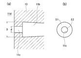
この金型10は、図5(a)、(b)に示す寸法(単位:mm)であり、同図(c)に示すように、そのキャビティ11は、1mm厚の扁平空洞部11aと、その空洞部11aの端から徐々に高さを増してその先端が円筒状となったほぼ角錐状空洞部11bと、その角錐状空洞部11bから貫通孔11cを介して連通した円筒状溜まり空隙部11dとからなる上下中央半割りのものである。図中、12は湯口(溶融樹脂注入口)である。
この金型10は、図5(a)、(b)に示す寸法(単位:mm)であり、同図(c)に示すように、そのキャビティ11は、1mm厚の扁平空洞部11aと、その空洞部11aの端から徐々に高さを増してその先端が円筒状となったほぼ角錐状空洞部11bと、その角錐状空洞部11bから貫通孔11cを介して連通した円筒状溜まり空隙部11dとからなる上下中央半割りのものである。図中、12は湯口(溶融樹脂注入口)である。
この金型10(キャビティ11)における貫通孔11cの径:d、角錐状空洞部11bの先端部の筒状部の径:Dとすると(図6参照)、その貫通孔11cの面積S2=d2×π/4、角錐状空洞部11bの先端部面積S1=D2×π/4-S2となる(図6参照)。
一方、コネクタ5の端子片用孔6の合計面積をそのキャビティ11におけるS2、その孔6を有する壁面積をそのキャビティ11におけるS1と考えることができる。
一方、コネクタ5の端子片用孔6の合計面積をそのキャビティ11におけるS2、その孔6を有する壁面積をそのキャビティ11におけるS1と考えることができる。
この考えに基づき、金型10(キャビティ11)に付、上下中央割りの中子13を交換することによって、下記表1に示す、S1、S2の異なるもの(No:1~14=S1/S2:0.1、0.5、0.8、1.0、5.0、10.0、20.0)を作成し、その各金型10に、下記表2最下欄に示す樹脂を注入(注入圧:0.1MPa)した実験結果を同表2に示す。その表2における各評価等はつぎのとおりである。
「樹脂漏れ」
×:樹脂漏れあり、△:孔6から見える程度ではあるが樹脂は漏れていない、○:樹脂漏れなし
「転写性」
×:成型物(樹脂被覆9)に欠けが発生し金型寸法通りにできていない、△:成型物は金型形状と同じであるが僅かに凹みがみられる、○:成型物が金型形状、寸法通りにできている
「溶融粘度」
射出成型機を用いたレオメータにより測定
「樹脂漏れ」
×:樹脂漏れあり、△:孔6から見える程度ではあるが樹脂は漏れていない、○:樹脂漏れなし
「転写性」
×:成型物(樹脂被覆9)に欠けが発生し金型寸法通りにできていない、△:成型物は金型形状と同じであるが僅かに凹みがみられる、○:成型物が金型形状、寸法通りにできている
「溶融粘度」
射出成型機を用いたレオメータにより測定

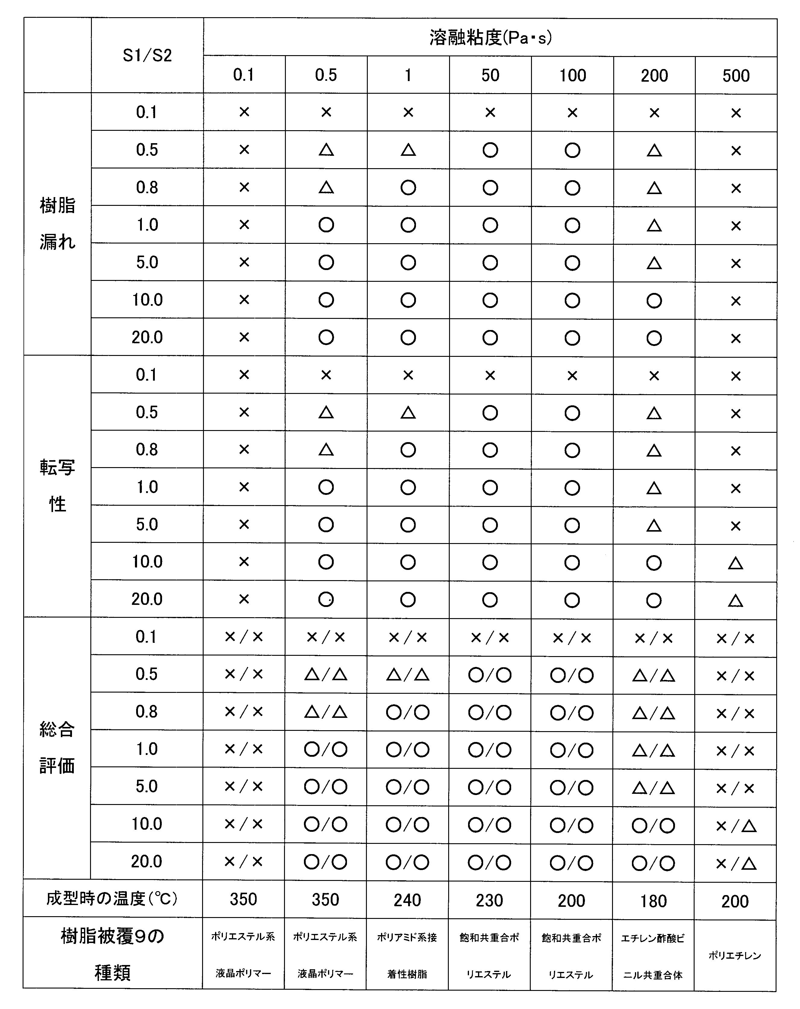
この実験例から、上記孔11cの全体面積S1とその11cの壁面積S2の比(S1/S2)を、0.5~20.0とし、上記樹脂被覆の溶融粘度を0.5~200Pa・sとすれば、表2の「樹脂漏れ」において、○又は△が得られ、「転写性」において、○又は△が得られていることから、孔11cからの溶融樹脂の漏れが無いことが理解できる。さらに、S1/S2:1.0~20.0、溶融粘度:0.5~100Pa・sの場合、「樹脂漏れ」及び「転写性」において、全て○が得られて優れている。
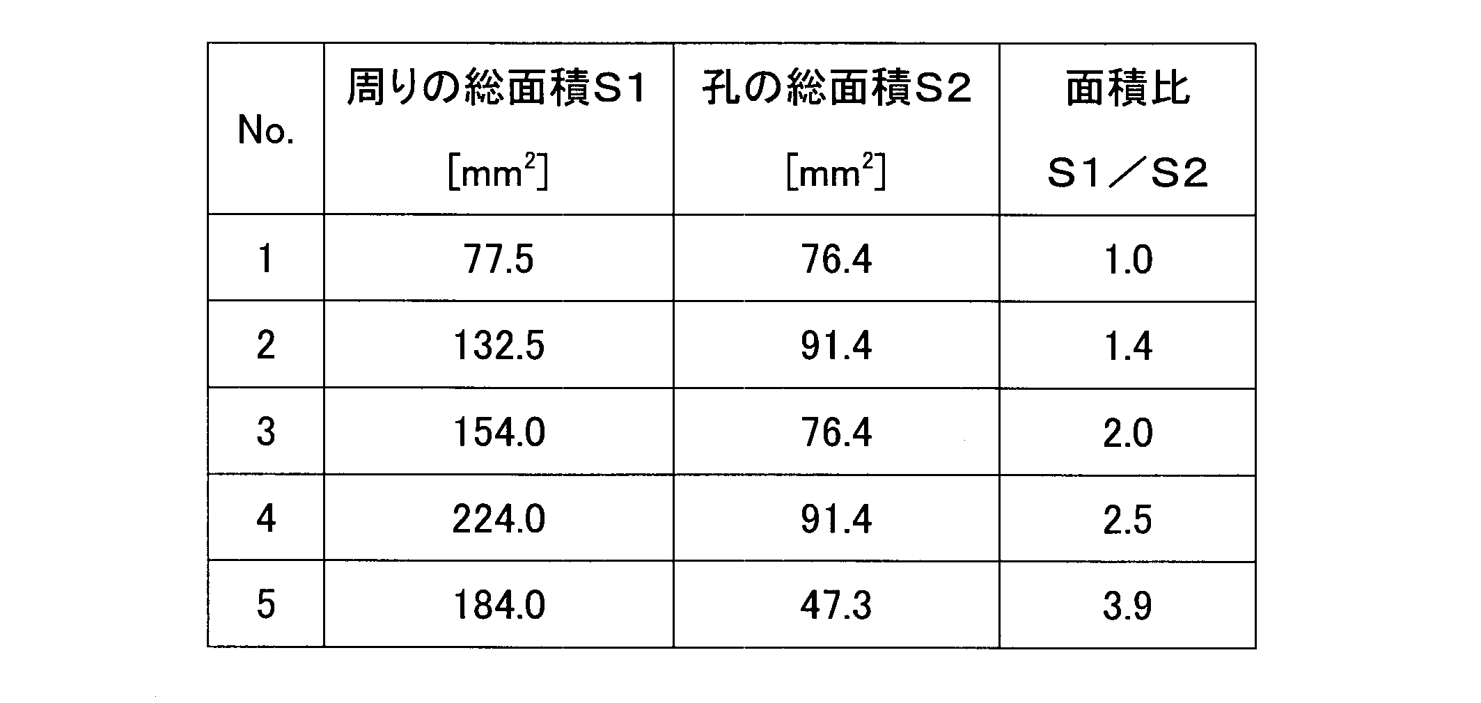
また、図1、図2で示した形状で、下記表3に示すS1、S2の各多心コネクタ5(孔6:30個(但し、図面では20個))において、樹脂被覆9を、ポリエステル系樹脂共重合体、溶融温度:約230℃、せん断速度:約15000s-1、溶融粘度:約100Pa・s、注入圧:0.1MPaで形成したところ、孔6から溶融樹脂が漏れることなく、転写性が優れた図3のケーブル1付コネクタ5を得た。このことから、上記孔6の面積:4mm2以下、その総和面積S1:120(4×30)mm2以下とすると良いことが窺える。
なお、ケーブル1は20心、30心に限定されないことは勿論であり、全ての絶縁心線3をコネクタ5に接続して(全ての端子片4を全ての孔6に差込んで)も良いし、仕様により、必要な絶縁心線3のみをコネクタ5に接続したりしても良い。
また、上記実施形態は、多心コネクタ5の全外周面に樹脂被覆9を行ったが、多心コネクタ5の外周面一部を残して樹脂被覆9をしても良く、また、雌型多心コネクタ5の場合であったが、図7に示す、雄型多心コネクタ5’の場合にあっても、この発明を採用できることは言うまでもない。
また、上記実施形態は、多心コネクタ5の全外周面に樹脂被覆9を行ったが、多心コネクタ5の外周面一部を残して樹脂被覆9をしても良く、また、雌型多心コネクタ5の場合であったが、図7に示す、雄型多心コネクタ5’の場合にあっても、この発明を採用できることは言うまでもない。
さらに、この発明は、ロボットケーブル等の屈曲性(柔軟性)に富んだケーブル以外でも採用できるが、特に、柔軟性に富んだケーブル1としては、具体的には、下記の評価方法による撚り骨上の硬さの測定値が80以下で、撚り骨上の硬さの測定値と撚り骨と撚り骨の中間部の硬さの測定値の差が5以上のものを採用し得る。
「評価方法」
JIS K6253に規定するデュロメータ硬さ試験のタイプAを用い、ケーブルを水平の鉄製台上に置き、ケーブル内部の絶縁線の撚り骨上に押針の先端がくるようにセットし、約10Nの力で垂直に圧し、5秒後の値を読み取り、その後、撚り骨と撚り骨の中間部に押針の先端をセットし、約10Nの力で垂直に圧し、5秒後の値を読み取り評価する。試験数は、各々5回の平均値とする。
「評価方法」
JIS K6253に規定するデュロメータ硬さ試験のタイプAを用い、ケーブルを水平の鉄製台上に置き、ケーブル内部の絶縁線の撚り骨上に押針の先端がくるようにセットし、約10Nの力で垂直に圧し、5秒後の値を読み取り、その後、撚り骨と撚り骨の中間部に押針の先端をセットし、約10Nの力で垂直に圧し、5秒後の値を読み取り評価する。試験数は、各々5回の平均値とする。
因みに、今回開示された実施の形態はすべての点で例示であって制限的なものではないと考えられるべきである。この発明の範囲は、上記した意味ではなく、特許請求の範囲によって示され、特許請求の範囲と均等の意味および範囲内でのすべての変更が含まれることが意図される。
1 多心ケーブル
2 ケーブルシース
3 絶縁心線
4 接続用端子片
5、5’ 多心コネクタ
6 多心コネクタの端子片用孔
8 樹脂被覆
9 樹脂被覆
10 金型
11 キャビティ
2 ケーブルシース
3 絶縁心線
4 接続用端子片
5、5’ 多心コネクタ
6 多心コネクタの端子片用孔
8 樹脂被覆
9 樹脂被覆
10 金型
11 キャビティ
Claims (4)
- 多数の端子片用孔(6)を有する多心コネクタ(5、5’)に、多数の絶縁心線(3)を有する多心ケーブル(1)をその絶縁心線(3)の端末に接続された前記端子片(4)を差込んで前記孔(6)に嵌入した多心ケーブル(1)と多心コネクタ(5、5’)との接続構造であって、
上記ケーブルシース(2)の端末と上記多心コネクタ(5、5’)との間には上記多心の絶縁心線(3)が露出して、その露出した多心の絶縁心線(3)の周りを含めて前記多心コネクタ(5、5’)とケーブルシース(2)端末とに亘って樹脂被覆(9)が形成されて多心コネクタ(5、5’)とケーブルシース(2)端末との間が閉塞され、その樹脂被覆(9)を介し多心コネクタ(5、5’)とケーブルシース(2)端末とに亘ってさらに樹脂被覆(8)が形成されており、かつ、前記孔(6)の全体面積(S2)とその孔(6)の壁面積(S1)の比(S1/S2)を0.5~20とし、前記最初の樹脂被覆(9)の溶融粘度を0.5~200Pa・sとしたことを特徴とする多心ケーブルと多心コネクタとの接続構造。 - 上記孔(6)の面積:4mm2以下、その総和面積(S2):120mm2以下としたことを特徴とする請求項1に記載の多心ケーブルと多心コネクタとの接続構造。
- 多数の端子片用孔(6)を有する多心コネクタ(5、5’)に、多数の絶縁心線(3)を有する多心ケーブル(1)をその絶縁心線(3)の端末に接続された前記端子片(4)を差込んで前記孔(6)に嵌入した多心ケーブル(1)と多心コネクタ(5、5’)との接続をなす方法であって、
上記ケーブルシース(2)の端末と上記多心コネクタ(5、5’)との間に露出した上記多心の絶縁心線(3)の周りを含めて前記多心コネクタ(5、5’)とケーブルシース(2)端末とに亘って樹脂被覆(9)を形成して多心コネクタ(5、5’)とケーブルシース(2)端末との間を閉塞し、その樹脂被覆(9)を介し多心コネクタ(5、5’)とケーブルシース(2)端末とに亘ってさらに樹脂被覆(8)を形成し、かつ、前記孔(6)の全体面積(S2)とその孔(6)の壁面積(S1)の比(S1/S2)を0.5~20とし、前記最初の樹脂被覆(9)の溶融粘度を0.5~200Pa・sとしたことを特徴とする多心ケーブルと多心コネクタとの接続方法。 - 上記孔(6)の面積:4mm2以下、その総和面積(S2):120mm2以下としたことを特徴とする請求項3に記載の多心ケーブルと多心コネクタとの接続方法。
Priority Applications (1)
| Application Number | Priority Date | Filing Date | Title |
|---|---|---|---|
| CN201280039013.9A CN103765689A (zh) | 2011-08-11 | 2012-08-07 | 多芯缆线与多芯连接器的连接构造 |
Applications Claiming Priority (2)
| Application Number | Priority Date | Filing Date | Title |
|---|---|---|---|
| JP2011-175699 | 2011-08-11 | ||
| JP2011175699A JP5373864B2 (ja) | 2011-08-11 | 2011-08-11 | 多心ケーブルと多心コネクタとの接続構造 |
Publications (1)
| Publication Number | Publication Date |
|---|---|
| WO2013021989A1 true WO2013021989A1 (ja) | 2013-02-14 |
Family
ID=47668496
Family Applications (1)
| Application Number | Title | Priority Date | Filing Date |
|---|---|---|---|
| PCT/JP2012/070054 Ceased WO2013021989A1 (ja) | 2011-08-11 | 2012-08-07 | 多心ケーブルと多心コネクタとの接続構造 |
Country Status (3)
| Country | Link |
|---|---|
| JP (1) | JP5373864B2 (ja) |
| CN (1) | CN103765689A (ja) |
| WO (1) | WO2013021989A1 (ja) |
Cited By (1)
| Publication number | Priority date | Publication date | Assignee | Title |
|---|---|---|---|---|
| JP2021191179A (ja) * | 2020-06-03 | 2021-12-13 | 住友電装株式会社 | 配線部材及び配線部材の製造方法 |
Families Citing this family (1)
| Publication number | Priority date | Publication date | Assignee | Title |
|---|---|---|---|---|
| JP7537233B2 (ja) * | 2020-11-06 | 2024-08-21 | 住友電気工業株式会社 | 光コネクタケーブル、及び光コネクタケーブルの製造方法 |
Citations (3)
| Publication number | Priority date | Publication date | Assignee | Title |
|---|---|---|---|---|
| JPS501418Y1 (ja) * | 1969-11-12 | 1975-01-16 | ||
| JPS614373U (ja) * | 1984-06-15 | 1986-01-11 | ヒロセ電機株式会社 | 電気コネクタ |
| JPH0742018U (ja) * | 1993-12-28 | 1995-07-21 | 矢崎総業株式会社 | 機器直付け型防水コネクタ |
Family Cites Families (17)
| Publication number | Priority date | Publication date | Assignee | Title |
|---|---|---|---|---|
| JPH08236196A (ja) * | 1995-02-23 | 1996-09-13 | Mitsumi Electric Co Ltd | Acアダプタ用dcコード |
| JP3045726B1 (ja) * | 1999-03-16 | 2000-05-29 | 株式会社サンテック | アンテナ線接続用l型コネクタ |
| TW416582U (en) * | 1999-04-06 | 2000-12-21 | Hon Hai Prec Ind Co Ltd | Electric connector |
| JP2001035583A (ja) * | 1999-05-20 | 2001-02-09 | Kawasaki Densen Kk | 電源プラグ |
| WO2002022954A1 (fr) * | 2000-09-18 | 2002-03-21 | Kao Corporation | Récipient moulé à couches multiples |
| JP4074289B2 (ja) * | 2002-08-08 | 2008-04-09 | 株式会社フジクラ | コネクタを備えた信号伝送ケーブルおよびその製造方法 |
| US6648676B1 (en) * | 2002-12-24 | 2003-11-18 | Hon Hai Precision Ind. Co., Ltd. | Cable end connector assembly |
| JP2005071892A (ja) * | 2003-08-27 | 2005-03-17 | Mitsumi Electric Co Ltd | L型コネクタ |
| JP2005158358A (ja) * | 2003-11-21 | 2005-06-16 | Mitsumi Electric Co Ltd | コネクタ |
| US6926562B1 (en) * | 2004-02-09 | 2005-08-09 | Hon Hai Precision Ind. Co., Ltd. | Cable end connector assembly with improved spacer |
| CN100524962C (zh) * | 2006-03-07 | 2009-08-05 | 东莞莫仕连接器有限公司 | 线缆连接器及其制造方法 |
| US7306479B1 (en) * | 2006-07-05 | 2007-12-11 | Hon Hai Precision Ind. Co., Ltd. | Cable connector assembly with strain relief member |
| CN101256545B (zh) * | 2007-03-02 | 2012-05-23 | 富士康(昆山)电脑接插件有限公司 | 线缆连接器组件 |
| JP4445982B2 (ja) * | 2007-06-29 | 2010-04-07 | ホシデン株式会社 | コネクタ |
| CN201323341Y (zh) * | 2008-12-11 | 2009-10-07 | 富士康(昆山)电脑接插件有限公司 | 线缆连接器组件 |
| CN201374440Y (zh) * | 2009-01-23 | 2009-12-30 | 东莞莫仕连接器有限公司 | 线缆连接器 |
| CN201369437Y (zh) * | 2009-03-24 | 2009-12-23 | 东莞市石碣志业电子有限公司 | 数据线插头 |
-
2011
- 2011-08-11 JP JP2011175699A patent/JP5373864B2/ja active Active
-
2012
- 2012-08-07 CN CN201280039013.9A patent/CN103765689A/zh active Pending
- 2012-08-07 WO PCT/JP2012/070054 patent/WO2013021989A1/ja not_active Ceased
Patent Citations (3)
| Publication number | Priority date | Publication date | Assignee | Title |
|---|---|---|---|---|
| JPS501418Y1 (ja) * | 1969-11-12 | 1975-01-16 | ||
| JPS614373U (ja) * | 1984-06-15 | 1986-01-11 | ヒロセ電機株式会社 | 電気コネクタ |
| JPH0742018U (ja) * | 1993-12-28 | 1995-07-21 | 矢崎総業株式会社 | 機器直付け型防水コネクタ |
Cited By (3)
| Publication number | Priority date | Publication date | Assignee | Title |
|---|---|---|---|---|
| JP2021191179A (ja) * | 2020-06-03 | 2021-12-13 | 住友電装株式会社 | 配線部材及び配線部材の製造方法 |
| JP7508865B2 (ja) | 2020-06-03 | 2024-07-02 | 住友電装株式会社 | 配線部材及び配線部材の製造方法 |
| US12463374B2 (en) | 2020-06-03 | 2025-11-04 | Sumitomo Wiring Systems, Ltd. | Wiring member and method for manufacturing wiring member |
Also Published As
| Publication number | Publication date |
|---|---|
| JP2013038045A (ja) | 2013-02-21 |
| JP5373864B2 (ja) | 2013-12-18 |
| CN103765689A (zh) | 2014-04-30 |
Similar Documents
| Publication | Publication Date | Title |
|---|---|---|
| US8002572B2 (en) | HDMI DIY field termination products | |
| TWI485935B (zh) | 具改良式電纜線管理件之通信插頭 | |
| CN103855476A (zh) | 电缆连接器、电缆组件以及电缆组件的制造方法 | |
| US6156976A (en) | Protective construction for splice portion | |
| US10630020B2 (en) | Cable connection structure and manufacturing method of the cable connection structure | |
| JP4794988B2 (ja) | 絶縁ケーブル端末 | |
| JP5373864B2 (ja) | 多心ケーブルと多心コネクタとの接続構造 | |
| JP5053449B2 (ja) | 絶縁ケーブル端末 | |
| WO2012032906A1 (ja) | コネクタ、端子付き電線、および端子 | |
| CN101499585A (zh) | 防水连接器及其制作方法 | |
| JP5483210B2 (ja) | 多心ケーブルと多心コネクタとの接続構造 | |
| US11230045B2 (en) | Method for overmolding at least one line | |
| CN100595976C (zh) | 设备插接装置和电路板插接装置的插座和插头及其制造方法 | |
| CN112134117A (zh) | 一种压接模具机电缆压接工艺 | |
| KR101164387B1 (ko) | 분기선의 케이블 접속장치 | |
| JP2010205502A (ja) | ケーブルアセンブリ | |
| US20090250240A1 (en) | Easily strippable electric cable | |
| CN106159572A (zh) | 信号线及其制造方法 | |
| KR101016968B1 (ko) | 리본형 연접전선의 제조 방법 | |
| HK1195401A (en) | Connection structure between multicore cable and multicore connector | |
| TWI711054B (zh) | 電線束 | |
| CN216120976U (zh) | 一种防折弯和拉伸的电磁热熔焊机连接线 | |
| JP7394091B2 (ja) | ワイヤハーネス | |
| JP5510738B2 (ja) | コネクタ | |
| CA2680911C (en) | Splice wire holder |
Legal Events
| Date | Code | Title | Description |
|---|---|---|---|
| 121 | Ep: the epo has been informed by wipo that ep was designated in this application |
Ref document number: 12822471 Country of ref document: EP Kind code of ref document: A1 |
|
| NENP | Non-entry into the national phase |
Ref country code: DE |
|
| 122 | Ep: pct application non-entry in european phase |
Ref document number: 12822471 Country of ref document: EP Kind code of ref document: A1 |