WO2013018786A1 - 負荷制御システムおよび負荷駆動システム - Google Patents
負荷制御システムおよび負荷駆動システム Download PDFInfo
- Publication number
- WO2013018786A1 WO2013018786A1 PCT/JP2012/069413 JP2012069413W WO2013018786A1 WO 2013018786 A1 WO2013018786 A1 WO 2013018786A1 JP 2012069413 W JP2012069413 W JP 2012069413W WO 2013018786 A1 WO2013018786 A1 WO 2013018786A1
- Authority
- WO
- WIPO (PCT)
- Prior art keywords
- driver
- load
- drivers
- script
- control system
- Prior art date
- Legal status (The legal status is an assumption and is not a legal conclusion. Google has not performed a legal analysis and makes no representation as to the accuracy of the status listed.)
- Ceased
Links
Images






Classifications
-
- H—ELECTRICITY
- H02—GENERATION; CONVERSION OR DISTRIBUTION OF ELECTRIC POWER
- H02J—ELECTRIC POWER NETWORKS; CIRCUIT ARRANGEMENTS OR SYSTEMS FOR SUPPLYING OR DISTRIBUTING ELECTRIC POWER; SYSTEMS FOR STORING ELECTRIC ENERGY
- H02J4/00—Circuit arrangements for mains or distribution networks not specified as AC or DC; Circuit arrangements for mains or distribution networks combining AC and DC sections or sub-networks
-
- G—PHYSICS
- G05—CONTROLLING; REGULATING
- G05B—CONTROL OR REGULATING SYSTEMS IN GENERAL; FUNCTIONAL ELEMENTS OF SUCH SYSTEMS; MONITORING OR TESTING ARRANGEMENTS FOR SUCH SYSTEMS OR ELEMENTS
- G05B19/00—Program-control systems
- G05B19/02—Program-control systems electric
- G05B19/18—Numerical control [NC], i.e. automatically operating machines, in particular machine tools, e.g. in a manufacturing environment, so as to execute positioning, movement or co-ordinated operations by means of program data in numerical form
- G05B19/414—Structure of the control system, e.g. common controller or multiprocessor systems, interface to servo, programmable interface controller
- G05B19/4141—Structure of the control system, e.g. common controller or multiprocessor systems, interface to servo, programmable interface controller characterised by a controller or microprocessor per axis
-
- H—ELECTRICITY
- H02—GENERATION; CONVERSION OR DISTRIBUTION OF ELECTRIC POWER
- H02B—BOARDS, SUBSTATIONS OR SWITCHING ARRANGEMENTS FOR THE SUPPLY OR DISTRIBUTION OF ELECTRIC POWER
- H02B3/00—Apparatus specially adapted for the manufacture, assembly, or maintenance of boards or switchgear
-
- H—ELECTRICITY
- H02—GENERATION; CONVERSION OR DISTRIBUTION OF ELECTRIC POWER
- H02P—CONTROL OR REGULATION OF ELECTRIC MOTORS, ELECTRIC GENERATORS OR DYNAMO-ELECTRIC CONVERTERS; CONTROLLING TRANSFORMERS, REACTORS OR CHOKE COILS
- H02P31/00—Arrangements for regulating or controlling electric motors not provided for in groups H02P1/00 - H02P5/00, H02P7/00 or H02P21/00 - H02P29/00
-
- G—PHYSICS
- G05—CONTROLLING; REGULATING
- G05B—CONTROL OR REGULATING SYSTEMS IN GENERAL; FUNCTIONAL ELEMENTS OF SUCH SYSTEMS; MONITORING OR TESTING ARRANGEMENTS FOR SUCH SYSTEMS OR ELEMENTS
- G05B2219/00—Program-control systems
- G05B2219/30—Nc systems
- G05B2219/33—Director till display
- G05B2219/33219—Drives, servo units, main control on internal net, lan, ethernet, tcp-ip, wireless
-
- G—PHYSICS
- G05—CONTROLLING; REGULATING
- G05B—CONTROL OR REGULATING SYSTEMS IN GENERAL; FUNCTIONAL ELEMENTS OF SUCH SYSTEMS; MONITORING OR TESTING ARRANGEMENTS FOR SUCH SYSTEMS OR ELEMENTS
- G05B2219/00—Program-control systems
- G05B2219/30—Nc systems
- G05B2219/39—Robotics, robotics to robotics hand
- G05B2219/39251—Autonomous distributed control, joint and link is a subsystem, communication intensive
-
- G—PHYSICS
- G05—CONTROLLING; REGULATING
- G05B—CONTROL OR REGULATING SYSTEMS IN GENERAL; FUNCTIONAL ELEMENTS OF SUCH SYSTEMS; MONITORING OR TESTING ARRANGEMENTS FOR SUCH SYSTEMS OR ELEMENTS
- G05B2219/00—Program-control systems
- G05B2219/30—Nc systems
- G05B2219/39—Robotics, robotics to robotics hand
- G05B2219/39252—Autonomous distributed control, task distributed into each subsystem, task space
Definitions
- the present invention relates to a load control system for controlling a load driving element for driving a load.
- a form in which a drive command is transmitted from a controller to a driver corresponding to the actuator, and the driver drives and controls the actuator according to the command is general.
- a controller is arranged for each actuator, and a control program for the actuator is set in each controller. Therefore, as the number of actuators to be driven increases, the control system It takes a lot of effort to build.
- an intelligent motor is formed integrally with the motor for the actuator control together with a motor driver as an actuator, and the intelligent motors are connected in series.
- the intelligent motor located at the uppermost stream in the serial connection form is positioned as a controller for controlling the whole, in other words, as a master controller. Therefore, even if the controller is not arranged for each actuator, the control program of the entire system set in the master controller is complicated and complicated because the master controller is substantially arranged. It must be enormous. Therefore, in terms of the control aspect of the actuator, the labor required for system construction is not much different from the conventional one.
- the present invention has been made in view of the above-described problems, and provides a load control system that facilitates construction of a control system when a plurality of load drive elements such as actuators for driving a load are controlled. Objective.
- a control unit is provided for each of the drive drivers of the load drive element, and drive control of the load drive element directly associated with each driver in the mutual communication between the control units.
- the mutual control communication state is formed so that it can be executed even by a command signal from another control unit.
- the present invention is a load control system including a plurality of drivers provided corresponding to the plurality of load driving elements in order to drive and control each of the plurality of load driving elements for driving the load.
- Each of the plurality of drivers has a control unit that controls the load driving element directly associated with the driver.
- each of the plurality of drivers is connected to the control unit of all or a part of the target drivers of other drivers excluding the driver from the control unit of the driver.
- a plurality of drivers are provided corresponding to the plurality of load drive elements, and each driver is provided with a control unit for controlling the load drive elements directly associated with the drivers.
- the load driving element referred to here is a control object electrically connected for load driving, and an actuator such as a motor that directly applies a force to the load by being controlled, or for control. Includes sensors that acquire necessary information.
- directly associated means that the driver is first assigned between one driver and one load driving element so that the driver can drive and control the load driving element. This means that it can be controlled in accordance with a command from another driver, and does not mean that the driver is exclusively used for driving control of the load driving element. That is, the drive control of the one load drive element by the one driver is expressed as “direct” based on the drive control of the one load drive element by the target driver in the mutual control communication state. is there.
- a mutual control communication state is formed among a plurality of drivers.
- a command signal for drive control is transmitted from the other target driver to the load driving element directly associated with the own driver, and the received own driver is received.
- drive control of the load drive element according to the command content is executed. That is, direct drive control is performed by the own driver, but a command signal related to the control content is issued from a target driver other than the own driver.
- the drive control of the entire system is distributed in the driver group including the own driver and the target driver without concentrating the drive control of the entire system in one place. An excessively large size can be suppressed, so that system construction such as program editing is facilitated.
- a load control system that facilitates the construction of the control system can be provided.
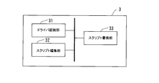
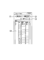
- FIG. 1 shows schematic structure of the load control system and load drive system which concern on the Example of this invention. It is a functional block diagram regarding the driver included in the load control system shown in FIG. It is a functional block diagram regarding the script rewriting apparatus contained in the load control system shown in FIG. It is a figure which shows the flow of control of the actuator performed with the load control system shown in FIG. It is a figure which shows the edit screen used as the script edit interface displayed on the script rewriting apparatus contained in the load control system shown in FIG. It is a figure which shows the edit screen used as the point table edit interface displayed on the script rewriting apparatus contained in the load control system shown in FIG. 1 is a diagram illustrating a schematic configuration of a robot to which a load control system according to an embodiment of the present invention is applied. It is a figure which shows the connection state between drivers in the robot shown in FIG.
- the load control system is a system for controlling a plurality of actuators and sensors for driving a load.
- the load control system 1 is a system including drivers D1 to D6 for driving six actuators A1 to A6 as shown in FIG.
- Each of the actuators A1 to A6 can be appropriately selected in order to realize a predetermined load drive desired by the user, and examples thereof include a motor that drives each joint of a robot having multiple joints.
- drivers D1 to D6 for driving each actuator are directly associated with each of the actuators A1 to A6.
- the actuators A1 and A2 are further connected to the actuators A1 and A2.
- the two-axis power supply PS1 supplies power according to instructions from the drivers D1 and D2, and the two-axis power supply PS2 supplies power to the actuators A3 and A4 according to instructions from the drivers D3 and D4.
- a power supply PS3 corresponding to two axes supplies power according to instructions from the drivers D5 and D6 for A5 and A6.
- the load drive system 2 according to the present invention is realized by the load control system 1 including the drivers D1 to D6, the actuators A1 to A6, and the power sources PS1 to PS3.
- power supplies PS1 to PS3 are provided as power supply devices for the load drive system 2.
- each actuator may be provided with a power supply, and power is supplied to all actuators. A single power supply may be used.
- each of the drivers D1 to D6 included therein is integrally provided with a control unit for driving and controlling the actuators A1 to A6.
- the control unit is formed by a dedicated processor, a program executed there, and the like.
- the controllers mounted in these drivers are daisy chain connected in series, and CAN (Controller Area Network) communication is possible between the controllers.
- Each of the drivers D1 to D6 is set with an ID for identifying each driver, and the ID is stored in the control unit of the driver.
- the IDs of the drivers D1 to D6 are set to ID01 to ID06.
- the drivers D1 to D6 are daisy chain connected in this order, the most upstream is the driver D1, and the most downstream driver D6 is provided with a terminator that means the end of the connection. ing.
- the script rewriting device 3 can be connected to the load control system 1 from the outside so that CAN communication is possible.
- the script rewriting device 3 is connected to the CAN communication line in the daisy chain connection, and the connection can rewrite a control script (program) for driving the actuator included in the plurality of drivers D1 to D6 connected in the daisy chain. Is possible. Therefore, when it is not necessary to rewrite the script, it is not necessary to establish a CAN communication connection between the script rewriting device 3 and the load control system 1.
- the script rewriting device 3 is formed as a personal computer or a microcomputer that executes the script rewriting program.
- FIG. 2A shows a functional block diagram in which the functions performed in the control unit of the driver D1 representing the drivers D1 to D6 are imaged.
- the function represented by the functional block is realized by a program executed by the control unit using hardware such as a processor, an input / output port, and a memory provided on the driver.
- the control executed by the script rewriting device 3 is displayed as a functional block and visualized.
- the control contents performed by the functional blocks are also realized by various methods such as a processor included in the script rewriting device 3 and a program executed therein.
- the input unit 11 is a functional unit to which data necessary for driving control of the actuator A1 directly supported by the driver D1 is input via the input port of the driver D1.
- this is a functional unit to which a command signal for the actuator A1 is input from a driver other than the driver D1 (that is, drivers D2 to D5).
- the output unit 12 is a command signal for driving the respective actuators directly associated with the drivers other than the driver D 1 (that is, the drivers D 2 to D 5) via the output port of the driver D 1.
- the ID holding unit 13 is a functional unit that holds the ID for identification set for each driver as described above. Specifically, the identification ID (ID01 in the case of the driver D1) is held in the memory on the driver D1.
- the coordinate data holding unit 14 is a functional unit that stores coordinate data belonging to a movable range that the actuator can take with respect to driving of the actuator A1.
- a command for directly specifying the coordinate of the movement destination of the actuator A1 is prepared, and coordinate data held in the coordinate data holding unit 14 is used as an argument of the command.
- the coordinate data holding unit 14 can hold up to 256 pieces of coordinate data.
- the script holding unit 15 includes a script including a program related to the drive control of the actuator A1 directly associated with the driver D1 and a program related to the drive control of the actuator (ie, the actuators A2 to A5) directly related to drivers other than the driver itself.
- the driver D1 is configured to be able to issue a drive command to an actuator directly associated with a driver other than the driver itself.
- the script rewriting accepting unit 16 is a functional unit that accepts a rewriting instruction when the script rewriting device 3 rewrites a script from the outside of the load control system 1.
- the script edited on the script rewriting device 3 side is received by the script rewriting accepting unit 16 together with the rewriting command, so that the drive control program (script) retained by the script retaining unit 15 is rewritten. become.
- the program execution unit 17 executes a drive control program (script) held by the script holding unit 15 and actually performs drive control of the actuator.
- the program is configured so that the actuator to be driven can be specified by the identification ID of the driver, whereby the actuator to be driven by the program execution unit 17 is daisy chain connected. All actuators A1 to A6 are used.
- the load control system 1 as a whole includes not only the actuator directly associated with the driver itself but also all or one of the other drivers other than the driver through the input unit and the output unit of each driver control unit. That is, a mutual control communication state is established in which a command signal for performing drive control of an actuator directly associated with the target driver can be transmitted to the target driver of the unit.
- this mutual control communication state is based on a mutual connection form of a plurality of drivers included in the load control system 1 (for example, a form in which all of the plurality of drivers are all connected in series, or a part of the plurality of drivers). , Regardless of the form of being connected in parallel to one driver included in the plurality of drivers). Therefore, the user can form a mutual control communication state without worrying about the connection order between the drivers, and can easily construct a system.
- the script rewriting device 3 includes a driver recognition unit 31, a script editing unit 32, and a script rewriting unit 33.
- the driver recognition unit 31 is a functional unit that recognizes a driver included in the load control system 1 in a state where the script rewriting device 3 is connected to the load control system 1 via a CAN communication connection.
- the driver recognized by the driver recognition unit 31 is a target of script editing or rewriting by the script rewriting device 3.
- the script editing unit 32 is a functional unit that performs editing processing such as addition, change, and deletion on a script held by the control unit of the driver included in the load control system 1. Details of editing the script will be described later.
- the script rewriting unit 33 is a functional unit that rewrites the script by reflecting the script editing performed by the script editing unit 32 in the script held by the script holding unit on the driver side.
- the rewriting of the script is performed through a CAN communication connection between the script rewriting device 3 and the load control system 1, and an input / output port of each driver and a daisy chain connection between the drivers.
- FIG. 3 refers to the drive control of the actuators A1 and A2.
- FIG. 3 is a schematic diagram of a script that each control unit of the drivers D1 and D2 has, and a point table that each control unit of the drivers D2 and D3 has.
- the point table is not shown for the driver D1
- the script is not shown for the driver D3.
- Each of the scripts and point tables may be provided as necessary.
- the script is a program group in which a control program for driving the actuator is described over a plurality of lines.
- a maximum of eight scripts are stored in the control unit of one driver.
- the script is configured to include a maximum of 99 lines of control programs.
- the point table is a table composed of combinations of movement positions and movement times required for moving the actuators. In the embodiment of the present invention, the point table has a maximum of 256 movement positions and movements. Time combinations can be included.
- the script is held by the script holding unit 15, and the point table is held by the coordinate data holding unit 14.
- the script Sc1 possessed by the control unit of the driver D1 shown in FIG. 3 is a script composed of seven lines of control programs from S11 to S17, and the script Sc2 possessed by the control unit of the driver D2 includes five lines from S21 to S25. It is a script consisting of the control program.
- excitation processing is performed in step S11.
- This excitation process is a process performed only for the actuator A1 directly associated with the driver D1 to be processed. Therefore, in the excitation process, the ID information of the own axis of the actuator to be processed or the driver directly associated therewith is designated. Accordingly, the actuator A1 is excited and activated in step S11.
- step S12 time / relative position movement processing is performed.
- the relative position movement referred to here means a relative movement based on the current position.
- This process is also a process performed only for the actuator A1 directly associated with the driver D1, similarly to the excitation process. Therefore, the time and the moving distance (number of pulses) relating to the relative position movement are set as arguments of the processing.
- the actuator A1 is subjected to a process of performing a relative movement of 1000 p (pulses) in a time of 200 ms.
- step S13 script execution processing is performed.
- This process is a process for executing a script included in the control unit of the driver other than the driver itself (driver D1 in this embodiment). Therefore, as an argument of the process, an ID of a driver holding a script to be executed and a script number to be executed by the driver specified by the ID are set.
- the script Sc2 included in the control unit of the driver D2 specified by ID02 is executed.
- the next step S14 is a step for performing a process of waiting for the completion of the operation.
- This operation completion waiting process is a process that does not proceed to the next step until the process that has been performed so far (the process of step S13 in this case) is completed. Accordingly, the script Sc2 is executed in step S13, and the processing after step S15 is not performed until the script Sc2 is completed.
- the script Sc2 will be briefly described. As shown on the right side of FIG. 3, the script Sc2 is a script composed of five lines of control programs from S21 to S25.
- step S21 excitation activation processing of the actuator A2 directly associated with the driver D2 is performed.
- step S22 similarly, a time / relative position movement process of the actuator A2 (a relative movement of 5000p in a time of 1000 ms) is performed.
- step S23 a process referred to as “point Go” is performed.
- the actuator associated with the driver having the designated ID performs a movement process of the actuator according to the designated point table.
- step S23 ID03 that is the ID of the driver D1 and PT1 that specifies the point table that the driver D3 has are set as arguments of the “point Go” process.
- the actuator A1 directly associated with the driver D1 is driven and controlled according to the designated point table PT1.
- the detailed form of the point table will be described later.
- step S24 a standby process is performed until the “point Go” process in step S23 is completed.
- the process proceeds to step S25, and an excitation cutoff process for the actuator A2 is performed.
- the drive control of the actuator specified by the script Sc2 is completed.
- the execution of Sc2 is started in step S13 included in the script Sc1 on the driver D1 side. Therefore, when the series of processes by the script Sc2 is completed, the operation completion confirmation in step S14 is performed.
- the process of step S15 is performed later.
- step S15 the process referred to as “point Go” described above is performed.
- ID02 that is the ID of the driver D2 and PT2 that specifies the point table that the driver D2 has are set as arguments of the “point Go” process.
- the actuator A2 directly associated with the driver D2 is driven and controlled according to the point table PT2.
- step S15 a process of waiting for operation completion is performed in step S16. Therefore, the processing after S17 is not performed until the “point Go” processing in step S15 is completed.
- the driver D2 notifies the driver D1 that the “point Go” process of the actuator A2 has been completed
- the operation completion is determined in step S16, and the process of step S17 is performed.
- step S17 an excitation cutoff process for the actuator A1 is performed.
- the driver D1 not only performs the drive control of the actuator A1 directly associated with the driver itself, but also daisy chain connection as shown in the processing of step S13 and step S15.
- the drive of the actuator A2 can also be controlled via the driver D2 connected at.
- the driver D2 not only the drive control of the actuator A2 directly associated with the driver itself but also the driver A1 via the driver D1 connected by daisy chain connection as shown in the process of step S23.
- the drive can also be controlled. That is, in the load control system 1, a mutual control communication state is formed in which a command signal for performing actuator drive control by a control unit included in the other driver can be transmitted to other drivers other than the driver itself. Has been.
- the system is constructed so that each of the drivers included in the load control system 1 can control the drive of all the actuators.
- the load control system 1 there is no master driver responsible for the control of the entire system, and the control of the entire system is distributed and assigned to each driver. Therefore, it is possible to avoid concentrating the control of the entire system on one driver, and the control program assigned to each driver can be made relatively small, so that maintenance such as change of the control program is easy and flexible.
- a control program is constructed.
- the drivers D1, D2, and D3 are referred to.
- the mutual control communication state can be formed in all the drivers connected by the daisy chain.
- the driver D1 From the driver D4, D6, etc., the drive control of the actuator A4 or A6 directly associated with these drivers may be performed, and conversely, the drive control of the actuator A1 directly associated with the driver D1 from the driver D4 May be performed.
- FIG. 4 is an image of an interface screen for script editing displayed on the display of the script rewriting device 3.
- FIG. 5 is an image of an interface screen for editing the point table shown in FIG.
- the program in the script rewriting device 3 is executed in a state where the script rewriting device 3 is physically connected to the load control system 1 via the “daisy chain” as shown in FIG. 1, the editing shown in FIG. A screen is displayed.
- the driver recognition unit 31 recognizes the driver connected to the script rewriting device 3.
- the script rewriting device 3 is electrically connected to the load control system 1.
- the button B1 is pressed in a state where the electrical connection state is maintained, the connection state is released, and the script rewriting device 3 cannot perform electrical processing on the load control system 1. It becomes.
- the area B ⁇ b> 2 is an area for selecting an ID given to a driver included in the load control system 1. Therefore, in this embodiment, ID01 to ID06 can be set.
- the area B3 is an area for selecting a script included in the driver selected in the area B2. In the present embodiment, as described above, each driver holds a maximum of eight scripts, so that one to eight scripts can be selected in the area B3.
- script information corresponding to the driver and script selected in the areas B2 and B3 is read from the script holding unit 15 included in the control unit of the driver. The read script information is displayed in the script display area B7.
- the script display area B7 is an area for displaying the script information so that it can be easily understood by the user and editing its contents. Therefore, the script information editing process in the script display area B7 corresponds to the editing process by the script editing unit 32. Further, in the script display area B7, it is necessary to press the button B5 in order to write a script edited as described later into the script holding unit 15 included in the control unit of a predetermined driver. The writing of the script by pressing the button B5 is performed on the script previously held by the script holding unit 15 via the script rewriting accepting unit 16 of the driver designated for writing (the driver selected in the area B2). On the other hand, since it is overwritten, it corresponds to the rewriting process by the script rewriting unit 33.
- a monitor area for monitoring the operation status such as the operation speed and output current of the actuator directly associated with the driver selected in the area B2 is provided above the script display area B7.
- This monitor area is useful for monitoring whether the actuator can be driven as expected by the edited script.
- the script operation can be confirmed by pressing a script operation button provided in the area B11.
- the numbers displayed on the script operation buttons correspond to the script numbers 1 to 8 held by each driver.
- the script display area B7 displays information on the selected script in a line number area B8, an action type area B9, and an action data area B10. Then, in the selected row, the user can select an action type to be executed by the actuator in the action type area B9, and input data (argument) necessary for the selected action type in the action data area B10.
- the operation types that can be selected in the operation type area B9 include, for example, the excitation process, time / relative position movement process, script execution process, operation completion wait process, and point Go process shown in FIG. Various useful processes can be selected.
- the data input in the action data area B10 differs depending on the action type selected in the action type area B9.
- the data necessary for the process is as follows.
- the ID of the driver having the script to be executed and the script number for specifying the script held in the driver are input.
- the excitation process or the operation completion waiting process is selected in the operation type area B9, it is not necessary to input data in the operation data area B10.
- the driving state requested by the user in the actuator is input to the script display area B7 in the processing order, and the script information of the driver specified by the button B5 is input. Can be easily written as.
- FIG. 5 illustrates an interface screen for editing the point table of the ID01 driver D1, and this screen has a read button C1, a write button C2, a point selection area C3, and a table display area C4.
- the read button C1 When the read button C1 is pressed, information on the point table (movement position and time required for movement) of the driver newly designated is displayed in the table display area C4.
- the point table information displayed and edited in the table display area C4 is overwritten in the coordinate data holding unit 14 of the designated driver control unit.
- a point to be focused in the table display area C4 is selected via the point selection area C3, and the selected point can be edited in the table display area C4.
- the maximum number of points in the point table is 256, 1 to 256 points can be selected in the point selection area.
- the point table of the driver can be edited and rewritten on the script rewriting device 3 side as well as the script.
- each driver holds a script and a point table so that the actuators of all axes can be controlled.
- an interface for editing and rewriting shown in FIGS. 4 and 5 is prepared in the script rewriting device 3, so that the user can edit scripts and point tables, Rewriting work can be easily performed.
- FIG. 6 is a diagram illustrating a schematic configuration of the robot 20 according to the present embodiment.
- arm members L1, L2, and L3 are sequentially connected by joint portions P1 and P2, and an end effector E1 is further attached to the tip of the arm member L3 via the joint portion P3.
- the joints P1, P2, and P3 are provided with actuators A1, A2, and A3 for driving the joints, and the end effector E1 is provided with an actuator A4 for opening and closing the joints.
- the specific structure for transmitting the driving force to the arm member and the end effector by each actuator is a conventional technique, the description is omitted.
- the load control system according to the present invention can be applied to the robot 20 configured as described above in order to control the actuators A1 to A4, and the connection state of the driver directly associated with each actuator when applied Is shown in FIG.
- FIG. 7 shows a state where the drivers D1 to D4 directly associated with the actuators A1 to A4 are connected in a daisy chain so that CAN communication is possible.
- a so-called centralized control device that is positioned as a master controller for controlling the entire robot 20 is provided.
- scripts (programs) relating to the control of the robot 20 can be distributed to the drivers D1 to D4 in a distributed manner.
- a script for controlling the actuator A1 is arranged in the driver D1
- a script for controlling the opening / closing of the end effector E1 by the actuator A4 is arranged in the driver D4.
- a script for executing a script for opening / closing control of the end effector E1 included in the driver D4 by using the script execution processing described with reference to FIG. 3 is arranged in the driver D1. Further, command signals relating to driving of the end effector E1 and other actuators may be transmitted from the other drivers D2 and D3. With this configuration, the distributed control shown in the first embodiment can be realized.
- the IDs assigned to the drivers of this embodiment are ID01 to ID03 for the drivers D1 to D3, and ID10 for the driver D4.
- the end effector attached to the joint part P3 can be replaced according to the application. That is, in the embodiment shown in FIG. 6, the end effector E1 can be replaced with the end effector E2.
- This end effector E2 has the same opening / closing structure for gripping as the end effector E1 from the viewpoint of gripping an object, but a camera C1 is mounted to enable more precise gripping control.
- the driver of the camera C1 directly associated with the camera C1 is connected as a driver D6 in a daisy chain so that CAN communication is possible with the driver D5 directly associated with the actuator A5 for opening / closing the opening / closing structure.
- the ID assigned to the driver D5 is ID10 which is the same as that of the driver D4, and the ID assigned to the driver D6 is ID11.
- a script for controlling the opening / closing of the end effector E2 by the actuator A5 is arranged in the driver D5, similarly to the driver D4.
- a script for precisely controlling the positioning of the end effector E2 through the input from the camera C1 is arranged in the driver D6, so that, for example, the end effector E2 is based on the command signals from the drivers D1 to D3. The coarse positioning of the end effector E2 can then be performed based on the command signal from the driver D6.
- the end effector to be used can be switched between E1 and E2 in accordance with the use of the end effector. If the end effector E1 is replaced with E2 and the driver D4 connected to the driver D3 is replaced with the drivers D5 and D6, a common ID may be assigned to D4 and D5.
- the robot 20 can be operated without greatly changing the control script for gripping the object by E2. That is, since the script for instructing opening / closing of the end effector E2 is arranged in the driver D1, the script for opening / closing control arranged in the driver D5 after replacement can be executed using the script. it can. Further, since the script for precise positioning of the end effector E2 described above is arranged in the driver D6, the precise positioning control can be executed by performing the above replacement, and the scripts on the drivers D1 to D3 are substantially executed. There is no need to edit manually.
- the above embodiment shows an application example of the load control system according to the present invention to a robot, it can be applied to a house as another embodiment.
- housing equipment include shutters, blinds, windows, locking devices, and the like. By opening / closing and locking / unlocking these with an actuator such as a motor, the safety and convenience of the housing can be improved. Even in such a case, the effects of the first and second embodiments can be obtained by connecting the drivers of the actuators in a daisy chain and disposing the control scripts in the control units of the drivers in a distributed manner. You can enjoy the effect. In other words, so-called house intelligentization (automatic control by electric equipment) can be realized with ease of maintenance.
Landscapes
- Engineering & Computer Science (AREA)
- Power Engineering (AREA)
- Manufacturing & Machinery (AREA)
- Physics & Mathematics (AREA)
- Human Computer Interaction (AREA)
- Microelectronics & Electronic Packaging (AREA)
- Computer Hardware Design (AREA)
- General Physics & Mathematics (AREA)
- Automation & Control Theory (AREA)
- Programmable Controllers (AREA)
- Control Of Multiple Motors (AREA)
- Manipulator (AREA)
- Control Of Electric Motors In General (AREA)
Abstract
Description
上記の実施例は、ロボットへの本発明に係る負荷制御システムの適用例を示すものであるが、その他の実施例として、住宅にも適用することが可能である。住宅の設備として、シャッター、ブラインド、窓、施錠装置等が挙げられるが、これらの開閉や施錠・解錠をモータ等のアクチュエータで行うことで、住宅の安全性や利便性の向上が図られる。このようなケースにおいても、各アクチュエータのドライバをデイジーチェインで接続し、各ドライバの制御部に、制御スクリプトを分散的に配置することで第1、第2の実施例で示した効果と同様の効果を享受することができる。すなわち、いわゆる住宅のインテリジェント化(電動機器による自動制御化)を、メンテナンス容易に実現することが可能となる。
2・・・・負荷駆動システム
3・・・・スクリプト書換装置
A1~A6・・・・アクチュエータ
D1~D6・・・・ドライバ
PS1~PS3・・・・電源
20・・・・ロボット
Claims (5)
- 負荷駆動のための複数の負荷駆動要素のそれぞれを駆動制御するために、該複数の負荷駆動要素に対応して設けられる複数のドライバを含む負荷制御システムであって、
前記複数のドライバのそれぞれは、自ドライバに直接関連付けられた前記負荷駆動要素を制御する制御部を有し、
前記複数のドライバのそれぞれは、前記負荷制御システムにおいて、自ドライバの前記制御部から該自ドライバを除く他のドライバの全部または一部の対象ドライバの前記制御部に対して、該対象ドライバに直接関連付けられた負荷駆動要素の駆動制御を行うための指令信号の送信が可能となる相互制御通信状態が形成されるように、互いに電気的に接続される、
負荷制御システム。 - 前記負荷制御システムにおいて、前記複数のドライバの相互の接続形態にかかわらず、前記相互制御通信状態は維持される、
請求項1に記載の負荷制御システム。 - 前記負荷制御システムに含まれる前記複数のドライバのそれぞれが有する前記制御部は、
前記複数のドライバのうち一のドライバが、別のドライバに交換された場合、該複数のドライバのうち該交換前の一のドライバを除く他のドライバから、該交換前の一のドライバに対する指令信号と同一の指令信号が、該交換後の別のドライバに対して出されても、該交換後の別のドライバに直接関連付けられた前記負荷駆動要素が、該交換前の一のドライバに直接関連付けられた前記負荷駆動要素の場合と同じ所定動作を実行するように、形成される、
請求項1又は請求項2に記載の負荷制御システム。 - 前記負荷制御システムにおいて、前記複数のドライバのそれぞれが全て直列に接続され、又は該複数のドライバの一部が、該複数のドライバに含まれる一のドライバに対して並列に接続される、
請求項1から請求項3の何れか一項に記載の負荷制御システム。 - 請求項1から請求項4の何れか一項に記載の負荷制御システムと、
前記負荷制御システムに含まれる複数のドライバに対応する前記複数の負荷駆動要素と、
前記複数の負荷駆動要素に電力を供給する電源装置と、
を備える、負荷駆動システム。
Priority Applications (3)
| Application Number | Priority Date | Filing Date | Title |
|---|---|---|---|
| DE112012003218.7T DE112012003218B4 (de) | 2011-08-01 | 2012-07-31 | Laststeuersystem und Lastantriebssystem |
| CN201280037776.XA CN103733149B (zh) | 2011-08-01 | 2012-07-31 | 负载控制系统以及负载驱动系统 |
| US14/236,561 US9318895B2 (en) | 2011-08-01 | 2012-07-31 | Load control system and load driving system |
Applications Claiming Priority (2)
| Application Number | Priority Date | Filing Date | Title |
|---|---|---|---|
| JP2011168493A JP5243580B2 (ja) | 2011-08-01 | 2011-08-01 | 負荷制御システムおよび負荷駆動システム |
| JP2011-168493 | 2011-08-01 |
Publications (1)
| Publication Number | Publication Date |
|---|---|
| WO2013018786A1 true WO2013018786A1 (ja) | 2013-02-07 |
Family
ID=47629307
Family Applications (1)
| Application Number | Title | Priority Date | Filing Date |
|---|---|---|---|
| PCT/JP2012/069413 Ceased WO2013018786A1 (ja) | 2011-08-01 | 2012-07-31 | 負荷制御システムおよび負荷駆動システム |
Country Status (6)
| Country | Link |
|---|---|
| US (1) | US9318895B2 (ja) |
| JP (1) | JP5243580B2 (ja) |
| CN (1) | CN103733149B (ja) |
| DE (1) | DE112012003218B4 (ja) |
| TW (1) | TWI548957B (ja) |
| WO (1) | WO2013018786A1 (ja) |
Cited By (1)
| Publication number | Priority date | Publication date | Assignee | Title |
|---|---|---|---|---|
| CN103984294A (zh) * | 2013-02-08 | 2014-08-13 | 控制技术有限公司 | 通信模块 |
Families Citing this family (13)
| Publication number | Priority date | Publication date | Assignee | Title |
|---|---|---|---|---|
| CN104143948B (zh) * | 2013-05-08 | 2017-06-27 | 上海微电子装备有限公司 | 一种通用电机驱动装置及驱动方法 |
| WO2015063864A1 (ja) | 2013-10-29 | 2015-05-07 | 株式会社安川電機 | モータ制御プログラム転送システム、上位コントローラ、モータ制御装置及びモータ制御プログラム転送方法 |
| JP6314426B2 (ja) * | 2013-10-31 | 2018-04-25 | セイコーエプソン株式会社 | ロボット制御装置およびロボット制御方法 |
| CN104608125B (zh) * | 2013-11-01 | 2019-12-17 | 精工爱普生株式会社 | 机器人、控制装置以及机器人系统 |
| EP3562100B1 (en) * | 2016-12-22 | 2023-05-17 | Nidec Corporation | Motor unit and multi-motor system |
| JP6915993B2 (ja) * | 2017-01-13 | 2021-08-11 | 日本電産株式会社 | モータ作動制御システム、多軸機械装置、モータ作動制御方法 |
| JP2019042856A (ja) * | 2017-08-31 | 2019-03-22 | 川崎重工業株式会社 | ロボット及びロボットの組立性確認方法 |
| JP6630333B2 (ja) * | 2017-10-31 | 2020-01-15 | 矢崎総業株式会社 | 車載制御装置 |
| US11347202B2 (en) * | 2018-06-19 | 2022-05-31 | Analogic Corporation | Multiple single axis servo drives with a dedicated inter-drive network |
| CN111868551A (zh) * | 2019-01-09 | 2020-10-30 | 深圳市大疆创新科技有限公司 | 测距装置及其扫描机构、控制方法、可移动平台 |
| JP7608292B2 (ja) * | 2021-08-13 | 2025-01-06 | 株式会社東芝 | ロボットハンド、ハンドリングシステム、ロボットハンド制御装置、ロボットハンドの制御方法、プログラム、及び記憶媒体 |
| KR102881775B1 (ko) * | 2024-10-04 | 2025-11-04 | 부산대학교 산학협력단 | 모터 드라이버 제어와 감시를 위한 휴먼 머신 인터페이스 제공 장치 |
| CN121056270A (zh) * | 2025-11-03 | 2025-12-02 | 深圳市华茂欧特科技有限公司 | 离散分布式负载驱动系统、方法、计算机设备及存储介质 |
Citations (3)
| Publication number | Priority date | Publication date | Assignee | Title |
|---|---|---|---|---|
| JPH06222816A (ja) * | 1993-01-21 | 1994-08-12 | Smc Corp | アクチュエータの制御方法および装置 |
| JPH08141957A (ja) * | 1994-11-11 | 1996-06-04 | Matsushita Electric Ind Co Ltd | ロボットの制御装置 |
| JP2000020109A (ja) * | 1998-06-30 | 2000-01-21 | Toshiba Lighting & Technology Corp | 遠隔監視制御システム |
Family Cites Families (22)
| Publication number | Priority date | Publication date | Assignee | Title |
|---|---|---|---|---|
| US4825133A (en) | 1986-08-05 | 1989-04-25 | Oki Electric Industry Co., Ltd. | Electromechanical actuator control system |
| JPH04290102A (ja) * | 1991-03-19 | 1992-10-14 | Mitsubishi Electric Corp | サーボ機構への情報伝送装置 |
| JPH05300606A (ja) * | 1992-04-21 | 1993-11-12 | Toshiba Corp | 電気車制御装置 |
| US5742143A (en) | 1995-01-20 | 1998-04-21 | Kabushiki Kaisha Sankyo Seiki Seisakusho | Motor control system with selectively operated A/D convertor |
| JP3647955B2 (ja) * | 1996-01-23 | 2005-05-18 | 三菱電機株式会社 | 操作ボード、リモートi/o通信制御方法 |
| JPH1013394A (ja) * | 1996-06-21 | 1998-01-16 | Fanuc Ltd | 通信における同期方法 |
| JPH10124131A (ja) * | 1996-10-22 | 1998-05-15 | Fanuc Ltd | 制御装置に接続される機器の管理方法 |
| JPH11299291A (ja) * | 1998-04-16 | 1999-10-29 | Sanyo Denki Co Ltd | 多軸モータ制御装置 |
| JP3964185B2 (ja) | 2001-11-08 | 2007-08-22 | 三菱電機株式会社 | モータのネットワーク制御システム |
| JP3807301B2 (ja) * | 2001-12-20 | 2006-08-09 | 松下電器産業株式会社 | モータ駆動装置 |
| JP4231941B2 (ja) | 2002-08-05 | 2009-03-04 | マッスル株式会社 | モータの制御方法およびモータの制御システム |
| JP3892778B2 (ja) * | 2002-08-28 | 2007-03-14 | ファナック株式会社 | 数値制御装置 |
| CN1251841C (zh) * | 2002-11-06 | 2006-04-19 | 中国科学院沈阳自动化研究所 | 一种模块化可变结构蛇形机器人 |
| JP3841762B2 (ja) * | 2003-02-18 | 2006-11-01 | ファナック株式会社 | サーボモータ制御システム |
| US7145300B2 (en) * | 2003-05-05 | 2006-12-05 | International Rectifier Corporation | Multi-axis AC servo control system and method |
| TWI222268B (en) * | 2003-08-26 | 2004-10-11 | Delta Electronics Inc | Fan system |
| US7508152B2 (en) * | 2005-08-29 | 2009-03-24 | The Boeing Company | Apparatus for machine tool feedrate override using limiting parameters corresponding to actual spindle speed |
| CN100441468C (zh) * | 2006-12-01 | 2008-12-10 | 华中科技大学 | 可分解重构的多足步行机器人 |
| US7274968B1 (en) * | 2006-12-26 | 2007-09-25 | Sodick Co., Ltd. | Method of serial communication method between NC device and a plurality of servo amps for servomotors |
| JP2009025879A (ja) * | 2007-07-17 | 2009-02-05 | Denso Wave Inc | ロボット装置の通信システム |
| CN100544899C (zh) * | 2007-10-26 | 2009-09-30 | 昆山华恒工程技术中心有限公司 | 一种开放式机器人系统 |
| US8569987B2 (en) * | 2010-09-21 | 2013-10-29 | Rockwell Automation Technologies, Inc. | Configurable multi-axis electric drive system concept |
-
2011
- 2011-08-01 JP JP2011168493A patent/JP5243580B2/ja active Active
-
2012
- 2012-07-31 DE DE112012003218.7T patent/DE112012003218B4/de active Active
- 2012-07-31 CN CN201280037776.XA patent/CN103733149B/zh active Active
- 2012-07-31 US US14/236,561 patent/US9318895B2/en active Active
- 2012-07-31 WO PCT/JP2012/069413 patent/WO2013018786A1/ja not_active Ceased
- 2012-08-01 TW TW101127777A patent/TWI548957B/zh active
Patent Citations (3)
| Publication number | Priority date | Publication date | Assignee | Title |
|---|---|---|---|---|
| JPH06222816A (ja) * | 1993-01-21 | 1994-08-12 | Smc Corp | アクチュエータの制御方法および装置 |
| JPH08141957A (ja) * | 1994-11-11 | 1996-06-04 | Matsushita Electric Ind Co Ltd | ロボットの制御装置 |
| JP2000020109A (ja) * | 1998-06-30 | 2000-01-21 | Toshiba Lighting & Technology Corp | 遠隔監視制御システム |
Cited By (2)
| Publication number | Priority date | Publication date | Assignee | Title |
|---|---|---|---|---|
| CN103984294A (zh) * | 2013-02-08 | 2014-08-13 | 控制技术有限公司 | 通信模块 |
| US9853831B2 (en) | 2013-02-08 | 2017-12-26 | Nidec Control Techniques Limited | Communication module |
Also Published As
| Publication number | Publication date |
|---|---|
| CN103733149A (zh) | 2014-04-16 |
| US20140152096A1 (en) | 2014-06-05 |
| JP2013033347A (ja) | 2013-02-14 |
| TW201329658A (zh) | 2013-07-16 |
| CN103733149B (zh) | 2016-10-19 |
| DE112012003218B4 (de) | 2021-11-04 |
| JP5243580B2 (ja) | 2013-07-24 |
| DE112012003218T5 (de) | 2014-07-24 |
| TWI548957B (zh) | 2016-09-11 |
| US9318895B2 (en) | 2016-04-19 |
Similar Documents
| Publication | Publication Date | Title |
|---|---|---|
| JP5243580B2 (ja) | 負荷制御システムおよび負荷駆動システム | |
| CN107848109B (zh) | 用于利用第三方贡献包扩展工业机器人的最终用户编程的方法 | |
| JPH10309685A (ja) | ロボット制御装置 | |
| CN107531440A (zh) | 操作纺织机的工作站的方法和操作设备 | |
| CN110497410A (zh) | 一种机器人控制系统及方法 | |
| CN107791244B (zh) | 控制器、作业控制装置、多轴动作控制装置和驱动控制装置 | |
| CN103403637B (zh) | 用于教导机器人移动的系统 | |
| CN115176209A (zh) | 机器人控制系统以及控制方法 | |
| CN109491331B (zh) | 控制系统、副控制装置及控制方法 | |
| CN205608427U (zh) | 一种舞台机械臂及应用该舞台机械臂的控制系统 | |
| US9971331B2 (en) | Monitoring device for programmable controller | |
| JP5058246B2 (ja) | 機械モデルを組み込まれた制御装置 | |
| JP5000624B2 (ja) | 制御システムおよび携帯型プログラマブル表示器 | |
| CN205466218U (zh) | 基于dmx512协议的伺服电机驱动装置及其舞台机械臂控制系统 | |
| KR101263487B1 (ko) | 로봇의 교시 장치 | |
| Kuts et al. | Digital twin: Universal user interface for online management of the manufacturing system | |
| KR20090005890A (ko) | 로봇 통합용접제어 시스템 | |
| JP4951783B2 (ja) | ロボット制御装置及びロボット制御方法 | |
| US12397433B2 (en) | Continuum arm robot system | |
| CN106808476B (zh) | 作业装置以及作业装置中的示教方法 | |
| KR20170055845A (ko) | 용접 로봇 제어시스템 및 그의 로봇 인식방법 | |
| JP7424028B2 (ja) | ロボット操作端末 | |
| CN120379798A (zh) | 调整机器人的姿势的装置、方法以及计算机程序 | |
| CN118647487A (zh) | 对具有选择动作模式的功能的工具进行切换的装置、示教装置、控制装置、机器人系统以及方法 | |
| WO2022208849A1 (ja) | ロボット制御装置、ロボット制御システム及びロボット制御方法 |
Legal Events
| Date | Code | Title | Description |
|---|---|---|---|
| 121 | Ep: the epo has been informed by wipo that ep was designated in this application |
Ref document number: 12820475 Country of ref document: EP Kind code of ref document: A1 |
|
| WWE | Wipo information: entry into national phase |
Ref document number: 14236561 Country of ref document: US |
|
| WWE | Wipo information: entry into national phase |
Ref document number: 112012003218 Country of ref document: DE Ref document number: 1120120032187 Country of ref document: DE |
|
| 122 | Ep: pct application non-entry in european phase |
Ref document number: 12820475 Country of ref document: EP Kind code of ref document: A1 |