WO2013015019A1 - 荷電粒子装置 - Google Patents
荷電粒子装置 Download PDFInfo
- Publication number
- WO2013015019A1 WO2013015019A1 PCT/JP2012/064154 JP2012064154W WO2013015019A1 WO 2013015019 A1 WO2013015019 A1 WO 2013015019A1 JP 2012064154 W JP2012064154 W JP 2012064154W WO 2013015019 A1 WO2013015019 A1 WO 2013015019A1
- Authority
- WO
- WIPO (PCT)
- Prior art keywords
- support
- lens barrel
- charged particle
- barrel
- particle device
- Prior art date
- Legal status (The legal status is an assumption and is not a legal conclusion. Google has not performed a legal analysis and makes no representation as to the accuracy of the status listed.)
- Ceased
Links
Images







Classifications
-
- H—ELECTRICITY
- H01—ELECTRIC ELEMENTS
- H01J—ELECTRIC DISCHARGE TUBES OR DISCHARGE LAMPS
- H01J37/00—Discharge tubes with provision for introducing objects or material to be exposed to the discharge, e.g. for the purpose of examination or processing thereof
- H01J37/02—Details
- H01J37/16—Vessels; Containers
-
- H—ELECTRICITY
- H01—ELECTRIC ELEMENTS
- H01J—ELECTRIC DISCHARGE TUBES OR DISCHARGE LAMPS
- H01J37/00—Discharge tubes with provision for introducing objects or material to be exposed to the discharge, e.g. for the purpose of examination or processing thereof
- H01J37/02—Details
- H01J37/04—Arrangements of electrodes and associated parts for generating or controlling the discharge, e.g. electron-optical arrangement or ion-optical arrangement
- H01J37/09—Diaphragms; Shields associated with electron or ion-optical arrangements; Compensation of disturbing fields
-
- H—ELECTRICITY
- H01—ELECTRIC ELEMENTS
- H01J—ELECTRIC DISCHARGE TUBES OR DISCHARGE LAMPS
- H01J37/00—Discharge tubes with provision for introducing objects or material to be exposed to the discharge, e.g. for the purpose of examination or processing thereof
- H01J37/02—Details
- H01J37/20—Means for supporting or positioning the object or the material; Means for adjusting diaphragms or lenses associated with the support
-
- H—ELECTRICITY
- H01—ELECTRIC ELEMENTS
- H01J—ELECTRIC DISCHARGE TUBES OR DISCHARGE LAMPS
- H01J2237/00—Discharge tubes exposing object to beam, e.g. for analysis treatment, etching, imaging
- H01J2237/02—Details
- H01J2237/0216—Means for avoiding or correcting vibration effects
-
- H—ELECTRICITY
- H01—ELECTRIC ELEMENTS
- H01J—ELECTRIC DISCHARGE TUBES OR DISCHARGE LAMPS
- H01J2237/00—Discharge tubes exposing object to beam, e.g. for analysis treatment, etching, imaging
- H01J2237/26—Electron or ion microscopes
Definitions
- the present invention relates to a charged particle device, and more particularly to a support structure for a lens barrel.
- a charged particle beam optical system In charged particle apparatuses such as a scanning electron microscope, a transmission electron microscope, a scanning transmission electron microscope, and a charged particle beam processing apparatus, a charged particle beam optical system is housed in a lens barrel.
- external vibration such as environmental sound or floor vibration is applied to the lens barrel, the charged particle beam optical system is affected.
- a relative displacement occurs between the electron beam and the sample. This relative displacement causes fluctuations in the observation image and reduces the resolution of the observation image. Since the resolution is extremely small, even if a minute vibration acts, it is affected.
- the charged particle device is provided with a structure or device for preventing external vibration from being transmitted to the lens barrel.
- a structure is known in which an apparatus main body is installed on a vibration isolation mount to reduce vibrations acting from the outside. Also known is a structure that reduces the amount of vibration of the device by increasing the rigidity of the device itself.
- Patent Document 1 describes a structure in which the upper end portion and the bottom portion of a lens barrel are coupled by a support.
- Patent Document 2 uses a structure that reinforces the bottom of the lens barrel and reduces the amount of device vibration due to external vibration.
- the axial length of the lens barrel tends to increase due to the higher functionality of charged particle devices.
- the natural frequency decreases and resonance tends to occur.
- the axial length of the lens barrel is extended by 40%, the natural frequency is approximately halved.
- the diameter of the lens barrel is increased approximately twice. In this case, the weight of the lens barrel becomes 5.6 times the original weight due to the weight increase due to the extension of the axial length and the weight increase due to the increase in the diameter of the lens barrel.
- ribs may be installed on all sides of the lens barrel.
- the height of the rib needs to be about 1.5 times the diameter of the lens barrel, and the structure itself becomes huge.
- the weight is 1.8 times the original.
- An object of the present invention is to provide a charged particle device that increases the rigidity of a lens barrel and reduces vibrations acting on the lens barrel without increasing the weight of the lens barrel itself.
- the charged particle apparatus supports a cylindrical barrel, a charged particle beam optical system provided in the barrel, a sample stage provided in the barrel, and the barrel. And a support device.
- the support device has a simple support structure that simply supports the lens barrel at a plurality of support points set along the axial direction of the lens barrel.
- the support point of the lens barrel is provided at a position corresponding to the position of the vibration node of the beam when the lens barrel is regarded as a beam having free ends.
- the barrel in the charged particle device, can be made highly rigid without increasing the weight of the barrel itself, and vibrations acting on the barrel can be reduced.
- the charged particle device includes a scanning electron microscope, a transmission electron microscope, a scanning transmission electron microscope, a charged particle beam (FIB) processing device, and the like.
- a scanning electron microscope a transmission electron microscope
- a scanning transmission electron microscope a scanning transmission electron microscope
- a charged particle beam (FIB) processing device a charged particle beam (FIB) processing device
- the structure of the transmission electron microscope will be described as an example.
- the transmission electron microscope is a device that performs nano-scale observation.
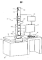
- the transmission electron microscope includes a main body 10, a load plate 18 that supports the main body 10, a gantry 20 that supports the load plate 18, a vibration isolation mount 19 provided between the load plate 18 and the gantry 20, a control device 14, and a display device. 15 and a console 16.
- the main body 10 has a lens barrel 102.
- the lens barrel 102 is a cylindrical container and has a long structure extending in the optical axis direction.
- the lens barrel 102 is provided with an electron gun 111, an emitter 112, a condenser lens 113, an objective lens 114, an intermediate lens 115, a projection lens 116, a detector 117, a fluorescent plate 118, and a camera film 119.
- a sample stage 103, an ion pump 104 and an exhaust pipe 105 are provided on the side surface of the lens barrel 102.
- the sample to be observed can be held in the sample holder at the tip of the sample stage 103.
- the sample holder is movable along the horizontal direction and the vertical direction, and is further rotatable around the axis of the sample stage 103, so that the sample can be inclined with respect to the horizontal plane.
- the ion pump 104 and the exhaust pipe 105 evacuate the inside of the lens barrel 102.
- the electron beam generated by the emitter 112 of the electron gun 111 is focused by the condenser lens 113 and irradiated on the sample at the tip of the sample stage 103.
- the electron beam that has passed through the sample is magnified by the objective lens 114, the intermediate lens 115, and the projection lens 116, detected by the detector 117, and imaged on the fluorescent screen 118 and the camera film 119.
- An observation image is obtained through the above process.
- the console 16 includes a control panel for operating the transmission electron microscope and a display device 15 that displays an observation image.
- the control device 14 transmits a command from the console 16 to each element of the transmission electron microscope.
- the lens barrel 102 is supported on the load plate 18. That is, the lens barrel 102 is cantilevered by the load plate 18. Providing the vibration isolation mount 19 between the load plate 18 and the gantry 20 prevents the vibration from the floor from being transmitted to the lens barrel 102.
- the lens barrel 102 has a cylindrical structure with a long axial length, and a sample stage 103, an ion pump 104, and an exhaust pipe 105 are provided on a side surface.
- Upper projections 120a, 120b, 120c, 120d and lower projections 121a, 121b, 121c, 121d are installed on the outer peripheral surface of the lens barrel 102.
- the positions of these protrusions in the axial direction will be described in detail later.
- These protrusions may have any shape as long as they have sufficient rigidity.
- the protrusion in the illustrated example has a fan shape, but may be a simple bar shape.
- the four protrusions in this example are provided at equal intervals in the circumferential direction on the outer peripheral surface of the lens barrel, but may be a single or an arbitrary plurality.
- the lens barrel 102 is supported by a support device.
- the support device has four columnar members 201, 202, 203, and 204 and two support members 211 and 212 that connect them.
- the four columnar members 201, 202, 203, 204 are arranged at equal intervals around the lens barrel 102.
- Columnar members 201, 202, 203, 204 are arranged on the floor.
- the columnar members 201, 202, 203, 204 are fixed to the floor by an appropriate method.
- the columnar members 201, 202, 203, and 204 may be fixed to the floor with anchor bolts.
- the columnar members 201, 202, 203, 204 may have any structure as long as they have sufficient rigidity.
- the cross-section of the columnar member may be any shape such as a circle or a rectangle.
- the columnar member may be constituted by a hollow member, but may be constituted by a solid member in order to improve vibration damping performance.
- a solid member may be formed by filling a hollow member with sand, concrete, or the like.
- the height of the columnar members 201, 202, 203, 204 may be approximately the same as that of the lens barrel 102, but may be higher than that of the lens barrel 102.
- the columnar members 201, 202, 203, and 204 may be provided with a fall prevention structure or a fall prevention function (not shown).
- a fall-preventing structure an inclined frame member may be connected to the columnar member, or a divergent support plate may be provided at the lower end of the columnar member.
- Support members 211 and 212 are each connected to a columnar member.
- the support members 211 and 212 are arranged so as to surround the lens barrel 102.
- the supporting members 211 and 212 may have any shape as long as they have sufficient rigidity.
- the support members 211 and 212 in this example are rectangular frame members.
- the upper protrusions 120 a, 120 b, 120 c, and 120 d of the lens barrel 102 are supported by the upper support member 211.
- the lower protrusions 121a, 121b, 121c, and 121d of the lens barrel 102 are supported by a lower support member 212.
- the load of the main body including the lens barrel 102 is evenly supported by the upper support member 211 and the lower support member 212.
- Anti-vibration mounts 130a, 130b, 130c, and 130d are provided between the upper protrusions 120a, 120b, 120c, and 120d of the lens barrel 102 and the upper support member 211, respectively.
- Anti-vibration mounts 131a, 131b, 131c, and 131d are provided between the lower projections 121a, 121b, 121c, and 121d of the lens barrel 102 and the lower support member 212, respectively.
- the anti-vibration mounts 130a to 130d and 131a to 131d may have any structure as long as they function to absorb and attenuate vibrations.
- the anti-vibration mount of this example may have a structure in which a spring and a damper are connected in series or in parallel.
- the anti-vibration mounts 130a to 130d and 131a to 131d have a mechanism for isolating vibrations in the horizontal and vertical directions of the lens barrel. Vibration from the floor is transmitted to the support members 211 and 212 via the columnar members 201, 202, 203, and 204. However, the vibrations of the support members 211 and 212 are prevented from being attenuated by the vibration isolation mounts 130a, 130b, 130c, and 130d and transmitted to the projections of the lens barrel. The sound wave in the air is transmitted to the lens barrel.
- the vibration of the lens barrel is attenuated by the vibration isolation mounts 130a, 130b, 130c, and 130d, and is prevented from being transmitted to the support members 211 and 212 and the columnar members 201, 202, 203, and 204.
- each of the columnar members 201 includes three parts: an upper part 201a, a central part 201b, and a lower part 201c. These three parts may be formed from separate members, but may be formed from a single member.
- the upper support member 211 and the lower support member 212 may be formed by separate members from the columnar members 201, 202, 203, and 204, but may be formed by the same member.
- the lower support member 212 is connected to the lower part 201c of the four columnar members 201, the central part 201b of the four columnar members 201 is connected thereto, and the upper support member 211 is provided thereon.
- the upper parts 201a of the four columnar members 201 may be connected to each other.
- the support device of this example includes four columnar members 301, 302, 303, and 304 and two support members 311 and 312 that connect them.
- the four columnar members 301, 302, 303, 304 are arranged at equal intervals around the lens barrel 102.
- Support members 311 and 312 are each connected to a columnar member.
- the support members 311 and 312 are arranged so as to surround the lens barrel 102.
- the support members 311 and 312 in this example have a rectangular frame member and an inward protrusion extending inwardly therefrom. The inward protrusion extends along the diagonal line of the frame member.
- the upper protrusions 120a, 120b, 120c, and 120d of the lens barrel 102 are supported by the inner protrusions 311a, 311b, 311c, and 311d of the upper support member 311.
- the lower protrusions 121a, 121b, 121c, and 121d of the lens barrel 102 are supported by the inner protrusions 312a, 312b, 312c, and 312d of the lower support member 312.
- the load of the main body including the lens barrel 102 is evenly supported by the upper support member 311 and the lower support member 312.
- Anti-vibration mounts 130a, 130b, 130c, and 130d are provided between the upper protrusions 120a, 120b, 120c, and 120d of the lens barrel 102 and the inner protrusions of the upper support member 311.
- Anti-vibration mounts 131a, 131b, 131c, and 131d are provided between the lower protrusions 121a, 121b, 121c, and 121d of the lens barrel 102 and the inner protrusions of the lower support member 312, respectively.
- the support device of this example is different from the first example shown in FIG. 2 in the structure of the support members 311 and 312 and the other configurations may be the same.
- each of the columnar members 301 includes three parts: an upper part 301a, a central part 301b, and a lower part 301c. These three parts may be formed from separate members, but may be formed from a single member.
- the upper support member 311 and the lower support member 312 may be formed of members that are separate from the columnar members 301, 302, 303, and 304, but may be formed of the same member.
- the lower support member 312 is connected on the lower portion 301c of the four columnar members 301, the central portion 301b of the four columnar members 301 is connected thereon, and the upper support member 311 is mounted thereon.
- the upper portions 301a of the four columnar members 301 may be connected to each other.
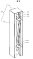
- the support device of this example includes a cover member 220.
- the support device of this example has a structure in which a cover member 220 is added to the first example of FIG. 2 or the second example of FIG. Therefore, although the support apparatus of this example has four columnar members and two support members that connect them, their description is omitted.
- the cover member 220 includes a side cover 222 and an upper surface cover 221.
- the cover member 220 is attached to the four columnar members so as to cover the entire barrel 102.
- One side surface of the cover member 220 may be openable and closable.
- the cover member 220 may have a shape other than the illustrated shape.
- the cover member 220 may be configured by a cylindrical container.
- the cover member 220 by providing the cover member 220, it is possible to avoid acoustic vibrations from acting directly on the lens barrel. Therefore, it is possible to reduce the sound pressure due to the sound from the surroundings acting on the lens barrel.
- the rigidity of the four columnar members can be increased by providing the cover member 220.
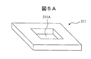
- the support member 211 in FIG. 5A is formed by a quadrangular frame member and has a quadrangular hole 211A at the center.
- the lens barrel 102 passes through the hole 211A.
- the projection of the lens barrel 102 is supported by a frame member.
- the support member 211 of FIG. 5A is used in the first example of FIG.
- the support member 311 in FIG. 5B is formed by a rectangular frame member and inward protrusions 311a, 311b, 311c, and 311d extending inwardly therefrom, and a circular hole 311A is formed at the center.
- the lens barrel 102 passes through the hole 311A.
- the protrusion of the lens barrel 102 is supported by an inward protrusion.
- the support member 311 of FIG. 5B is used in the second example of FIG.
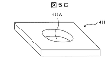
- the support member 411 in FIG. 5C is formed by a rectangular frame member, and has a circular hole 411A at the center.
- the lens barrel 102 passes through the hole 411A.
- the projection of the lens barrel 102 is supported by a frame member.
- FIG. 6 is a schematic view of the lens barrel 102 and the support device in the charged particle device according to the present invention.
- the support device includes columnar members 201 and 202, an upper support member 211, and a lower support member 212.
- the columnar members 201 and 202 are disposed on the floor.
- upper protrusions 120a and 120c and lower protrusions 121a and 121c are provided on the outer periphery of the lens barrel 102.
- the upper protrusions 120a and 120c of the lens barrel 102 are supported by the upper support member 211 of the support device via the vibration isolation mounts 130a and 130c.
- the lower protrusions 121a and 121c of the lens barrel 102 are supported by a lower support member 212 of the support device via vibration isolation mounts 131a and 131c.
- the position coordinates x1 and x2 of the protrusion correspond to the positions of the nodes of the vibration primary mode or the secondary mode when both ends of the lens barrel 102 are free ends.
- the protrusions 120a, 120c, 121a, and 121c are provided at the positions of the vibration primary mode or secondary mode nodes when both ends of the lens barrel 102 are free ends, and the protrusions are supported by the support member of the support device.
- the displacement of the lens barrel 102 is zero.
- resonance does not occur even if floor vibration is transmitted to the lens barrel 102.
- the lens barrel 102 is simply supported by the simple support structure, the natural frequency is higher than that in the case where the lens barrel 102 is cantilevered as in the conventional charged particle device, and the resonance is increased. Can be suppressed. This will be described in detail later.
- the lens barrel uses a simple support structure that simply supports at the support point. Unlike the cantilever support structure, the simple support structure constrains the displacement of the beam at the support point but allows the beam to tilt.
- a simple support structure is used.
- the simple support structure is provided between the protrusion 120a of the lens barrel 102 and the support member 211 of the support device.
- the simple support structure includes a pin 145 provided on the protrusion 120 a of the lens barrel 102 and a support mount 140 that can rotate around the pin 145.
- the support mount 140 is fixed to the support member 211.
- the simple support structure allows the projection 120a of the lens barrel 102 to be rotationally displaced around the pin 145, but does not allow the projection 120a of the lens barrel 102 to be displaced in the horizontal direction and the vertical direction with respect to the support mount 140. Therefore, the simple support structure allows only the tilt of the lens barrel 102 and prevents the horizontal and vertical displacement of the lens barrel 102.
- a roller support structure is used.
- the roller support structure is a kind of simple support structure.
- the roller support structure is provided between the protrusion 120a of the lens barrel 102 and the support member 211 of the support device.
- the roller support structure includes a pin 145 provided on the projection 120 a of the lens barrel 102, a support mount 140 that can rotate around the pin 145, and a roller 146 that is disposed between the lower end of the support mount 140 and the support member 211.
- the roller support structure allows the protrusion 120a of the lens barrel 102 to be rotationally displaced around the pin 145, but does not allow the protrusion 120a of the lens barrel 102 to be displaced in the horizontal direction and the vertical direction with respect to the support mount 140.
- the support mount 140 is movable in the horizontal direction with respect to the support member 211 via the roller 146. Therefore, the roller support structure allows tilting and horizontal movement of the lens barrel 102, and prevents vertical displacement of the lens barrel 102.
- the above-described vibration isolation mount 130a is not shown.
- the vibration isolation mount described above may be incorporated into the support mount 140, or the vibration isolation mount described above may be provided in series with the support mount 140.
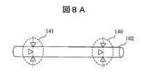
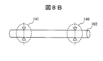
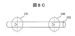
- the lens barrel 102 is supported at three points in the upper and lower portions of the support device.
- Three support mounts 140 and 141 are attached to each support point.
- One of the three support mounts supports the lens barrel 102 along the axial direction, and two supports the lens barrel 102 along the direction perpendicular to the axial direction.
- the lens barrel 102 is supported at two points on the upper and lower portions of the support device.
- Two support mounts 140 and 141 are attached to each support point. These support mounts support the lens barrel 102 from a direction perpendicular to the axial direction.
- the lens barrel 102 is supported at one point in the upper and lower portions of the support device.
- One support mount 140, 141 is attached to each support point.
- the support mount supports the lens barrel 102 along the axial direction.
- the lens barrel 102 may be supported from below, but may be supported so as to suspend the lens barrel 102 from above.
- the vibration mode and the natural frequency of the support structure of the lens barrel in the conventional charged particle device and the support structure of the lens barrel according to the present invention will be compared.
- the lens barrel is regarded as a bar having a uniform cross-sectional area and material.
- transverse vibration of the beam When the bar vibrates transversely to the axis, it is called transverse vibration of the beam and is represented by four differential equations. Using the boundary conditions at both ends of the beam, a fourth-order differential equation can be solved. In this way, a vibration curve is obtained.
- the vibration can be a primary mode, a secondary mode, a tertiary mode, or the like.
- the natural frequency is expressed by equation (1).
- E is the Young's modulus of the lens barrel
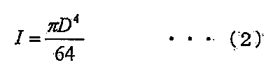
- I is the moment of inertia of the cross section of the lens barrel
- ⁇ is the axial density of the lens barrel
- A is the cross sectional area of the lens barrel
- l is the length of the lens barrel.
- ⁇ is a coefficient determined by the beam support method and the vibration order.
- the cross-sectional secondary moment I of the lens barrel is expressed by equation (2).
- FIG. 9A shows the vibration mode of a cantilevered beam.
- the lens barrel In the conventional charged particle device, the lens barrel is supported on a load plate. Therefore, the lens barrel can be approximated by a cantilevered beam.
- the largest amplitude appears at the free end of the beam.
- FIG. 9B shows the vibration mode of a beam with both ends being free ends.
- the largest amplitude appears at the center of the beam and the free ends at both ends.
- the amplitude increases at the middle of the node and at the free ends at both ends.
- the position of the node when the lens barrel vibrates is set as the support point of the lens barrel. Therefore, even if floor vibration is transmitted to the lens barrel 102, resonance does not occur.
- the natural frequency is proportional to the square of the coefficient ⁇ .
- the natural frequency when both ends shown in FIG. 8B are free ends is 6 times or more the natural frequency in the case of the cantilever support structure shown in FIG. 8A.
- the natural frequency of the beam having both ends simply supported can be obtained.
- the natural frequency in this case is twice or more the natural frequency in the case of the cantilever support structure shown in FIG. 8A.
- the support point of the lens barrel is set at a position corresponding to the vibration node of the beam whose both ends are free ends.
- the support point of the lens barrel may be set at a position corresponding to the vibration node of the beam with one end being simply supported and the other end being a free end.
- the simple support structure is used instead of the cantilever support structure, the natural frequency of the lens barrel can be increased as compared with the conventional charged particle device. Therefore, resonance of the lens barrel can be prevented.
- the support point of the lens barrel is set at a position corresponding to the vibration node of the beam, even if vibration is transmitted from the outside to the lens barrel, resonance of the lens barrel can be avoided. .
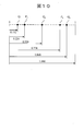
- Points P1 and P2 are positions of vibration nodes when the vibration of the beam whose both ends are free ends is in the first-order mode.
- Points Q1, Q2, and Q3 are positions of vibration nodes when the vibration of the beam whose both ends are free ends is in the secondary mode.
- the points P1 and P2 may be used as support points for the lens barrel.
- points Q1, Q2, and Q3 may be used as support points for the lens barrel.
- a first support point is set between the points P1 and Q1
- a second support point is set between the points P2 and Q3. It may be set.
- the first support point may be arranged in the middle of the points P1 and Q1
- the second support point may be arranged in the middle of the points P2 and Q3.
- the support point of the lens barrel may be set at the position of the vibration node, but may be set near the position of the vibration node. Even if the support point of the lens barrel is set in the vicinity of the position of the vibration node, resonance of the lens barrel can be prevented.
- the lens barrel can be made highly rigid without increasing the weight of the lens barrel itself, and the vibration of the lens barrel itself and the vibration acting on the lens barrel can be reduced.
- protrusions 121a, 121b, 121c, 121d ... protrusions, 130a-130d and 131a-131d ... vibration mounts, 140, 141 ... support mounts, 145 ... pins, 146 ... rollers, 201, 202, 203, 204 ... Columnar members, 211, 212 ... Support members, 220 ... Cover members, 221 ... Surface cover, 222 ... side cover, 301, 302, 303, 304 ... columnar member, 311, 312 ... support member, 312a, 312b, 312c, 312d ... inward projections
Landscapes
- Chemical & Material Sciences (AREA)
- Analytical Chemistry (AREA)
- Vibration Prevention Devices (AREA)
- Exposure Of Semiconductors, Excluding Electron Or Ion Beam Exposure (AREA)
- Exposure And Positioning Against Photoresist Photosensitive Materials (AREA)
Abstract
Description

Claims (20)
- 筒形の鏡筒と、該鏡筒の内部に設けられた荷電粒子線光学系と、該鏡筒に設けられた試料ステージと、前記鏡筒を支持する支持装置と、を有する荷電粒子装置において、
前記支持装置は、前記鏡筒の軸線方向に沿って設定された複数の支持点にて前記鏡筒を単純支持する単純支持構造を有し、
前記鏡筒の支持点は、前記鏡筒を両端が自由端である梁と看做したときの梁の振動の節の位置に対応する位置に設けられていることを特徴とする荷電粒子装置。 - 請求項1記載の荷電粒子装置において、
前記梁の振動が1次モードのときの2つの節の位置を順に点P1、P2とするとき、前記鏡筒の支持点は、該点P1、P2に対応する位置に設けられていることを特徴とする荷電粒子装置。 - 請求項1記載の荷電粒子装置において、
前記梁の振動が1次モードのときの2つの節の位置を順に点P1、P2とし、前記振動が2次モードのときの3つの節の位置を順に点Q1、Q2、Q3とするとき、前記鏡筒の支持点は、該点P1と点Q1の間の第1の支持点と、該点P2と点Q3の間の第2の支持点として設けられていることを特徴とする荷電粒子装置。 - 請求項1記載の荷電粒子装置において、
前記鏡筒の外周には前記支持点に対応する位置に突起が設けられ、
前記支持装置は、床上に配置された4本の柱状部材と、該柱状部材を接続する支持部材とを有し、前記支持部材によって、前記鏡筒の突起が支持されていることを特徴とする荷電粒子装置。 - 請求項4記載の荷電粒子装置において、
前記鏡筒の突起と前記支持部材の間に前記鏡筒を除振支持する除振マウントが設けられていることを特徴とする荷電粒子装置。 - 請求項4記載の荷電粒子装置において、
前記支持部材は、前記鏡筒が貫通する孔を有する枠部材を有することを特徴とする荷電粒子装置。 - 請求項1記載の荷電粒子装置において、
前記支持装置はカバーで覆われていることを特徴とする荷電粒子装置。 - 請求項1記載の荷電粒子装置において、
前記単純支持構造は、前記鏡筒に設けられたピンと、該ピン周りに回転可能な支持マウントとを有し、該支持マウントは前記支持装置に固定されていることを特徴とする荷電粒子装置。 - 請求項1記載の荷電粒子装置において、
前記単純支持構造は、前記鏡筒に設けられたピンと、該ピン周りに回転可能な支持マウントと、該支持マウントの下端部と前記支持装置の間に設けられたローラと、を有するローラ支持構造によって構成されていることを特徴とする荷電粒子装置。 - 筒形の鏡筒と、該鏡筒の内部に設けられた荷電粒子線光学系と、該鏡筒に設けられた試料ステージと、前記鏡筒を支持する支持装置と、を有する荷電粒子装置において、
前記支持装置は、前記鏡筒の軸線方向に沿って設定された複数の支持点にて前記鏡筒を単純支持する単純支持構造を有し、
前記鏡筒の支持点は、前記鏡筒を両端が単純支持された梁と看做したときの梁の振動の節の位置に対応する位置に設けられていることを特徴とする荷電粒子装置。 - 請求項10記載の荷電粒子装置において、
前記鏡筒の外周には前記支持点に対応する位置に突起が設けられ、
前記支持装置は、床上に配置された4本の柱状部材と、該柱状部材を接続する支持部材とを有し、前記支持部材によって、前記鏡筒の突起が支持されていることを特徴とする荷電粒子装置。 - 請求項11記載の荷電粒子装置において、
前記鏡筒の突起と前記支持部材の間に前記鏡筒を除振支持する除振マウントが設けられていることを特徴とする荷電粒子装置。 - 請求項10記載の荷電粒子装置において、
前記支持装置はカバーで覆われていることを特徴とする荷電粒子装置。 - 請求項10記載の荷電粒子装置において、
前記単純支持構造は、前記鏡筒に設けられたピンと、該ピン周りに回転可能な支持マウントとを有し、該支持マウントは前記支持装置に固定されていることを特徴とする荷電粒子装置。 - 請求項10記載の荷電粒子装置において、
前記単純支持構造は、前記鏡筒に設けられたピンと、該ピン周りに回転可能な支持マウントと、該支持マウントの下端部と前記支持装置の間に設けられたローラと、を有するローラ支持構造によって構成されていることを特徴とする荷電粒子装置。 - 筒形の鏡筒と、該鏡筒の内部に設けられた荷電粒子線光学系と、該鏡筒に設けられた試料ステージと、前記鏡筒を支持する支持装置と、を有する荷電粒子装置において、
前記支持装置は、前記鏡筒の軸線方向に沿って設定された複数の支持点にて前記鏡筒を単純支持する単純支持構造を有し、
前記鏡筒の支持点は、前記鏡筒を両端が自由端である梁と看做したときの梁の振動の節の位置に対応する位置に設けられ、
前記鏡筒の外周には前記支持点に対応する位置に突起が設けられ、該鏡筒の突起を介して前記鏡筒は前記支持装置によって支持されていることを特徴とする荷電粒子装置。 - 請求項16記載の荷電粒子装置において、
前記支持装置は、床上に配置された4本の柱状部材と、該柱状部材を接続する支持部材とを有し、前記支持部材によって、前記鏡筒の突起が支持されており、
前記鏡筒の突起と前記支持部材の間に前記鏡筒を除振支持する除振マウントが設けられていることを特徴とする荷電粒子装置。 - 請求項16記載の荷電粒子装置において、
前記単純支持構造は、前記鏡筒の突起に設けられたピンと、該ピン周りに回転可能な支持マウントとを有し、該支持マウントは前記支持装置に固定されていることを特徴とする荷電粒子装置。 - 請求項16記載の荷電粒子装置において、
前記単純支持構造は、前記鏡筒の突起に設けられたピンと、該ピン周りに回転可能な支持マウントと、該支持マウントの下端部と前記支持装置の間に設けられたローラと、を有するローラ支持構造によって構成されていることを特徴とする荷電粒子装置。 - 請求項16記載の荷電粒子装置において、
前記支持装置はカバーで覆われていることを特徴とする荷電粒子装置。
Priority Applications (3)
| Application Number | Priority Date | Filing Date | Title |
|---|---|---|---|
| US14/232,816 US8927930B2 (en) | 2011-07-25 | 2012-05-31 | Charged particle device |
| CN201280027699.XA CN103597571B (zh) | 2011-07-25 | 2012-05-31 | 带电粒子装置 |
| DE112012002764.7T DE112012002764B4 (de) | 2011-07-25 | 2012-05-31 | Ladungsteilchenstrahlvorrichtung |
Applications Claiming Priority (2)
| Application Number | Priority Date | Filing Date | Title |
|---|---|---|---|
| JP2011-162368 | 2011-07-25 | ||
| JP2011162368A JP5420601B2 (ja) | 2011-07-25 | 2011-07-25 | 荷電粒子装置 |
Publications (1)
| Publication Number | Publication Date |
|---|---|
| WO2013015019A1 true WO2013015019A1 (ja) | 2013-01-31 |
Family
ID=47600879
Family Applications (1)
| Application Number | Title | Priority Date | Filing Date |
|---|---|---|---|
| PCT/JP2012/064154 Ceased WO2013015019A1 (ja) | 2011-07-25 | 2012-05-31 | 荷電粒子装置 |
Country Status (5)
| Country | Link |
|---|---|
| US (1) | US8927930B2 (ja) |
| JP (1) | JP5420601B2 (ja) |
| CN (1) | CN103597571B (ja) |
| DE (1) | DE112012002764B4 (ja) |
| WO (1) | WO2013015019A1 (ja) |
Cited By (1)
| Publication number | Priority date | Publication date | Assignee | Title |
|---|---|---|---|---|
| WO2016135430A1 (fr) | 2015-02-27 | 2016-09-01 | Centre National De La Recherche Scientifique | Particules d'acide hyaluronique pour des applications cosmétiques ou dermatologiques |
Families Citing this family (4)
| Publication number | Priority date | Publication date | Assignee | Title |
|---|---|---|---|---|
| JP6608329B2 (ja) * | 2016-04-21 | 2019-11-20 | 株式会社ニューフレアテクノロジー | 荷電粒子ビーム装置 |
| JP2018005975A (ja) | 2016-06-27 | 2018-01-11 | 株式会社日立ハイテクノロジーズ | 荷電粒子線装置に取り付けられる振動抑制機構、及び荷電粒子線装置 |
| JP6633986B2 (ja) * | 2016-07-20 | 2020-01-22 | 株式会社日立ハイテクノロジーズ | 荷電粒子線装置 |
| JP2019121688A (ja) | 2018-01-05 | 2019-07-22 | 株式会社ニューフレアテクノロジー | 制振システム及び、その制振システムを備える光学装置 |
Citations (5)
| Publication number | Priority date | Publication date | Assignee | Title |
|---|---|---|---|---|
| JPH08320570A (ja) * | 1995-05-25 | 1996-12-03 | Hitachi Ltd | 電子線描画装置 |
| JPH11154698A (ja) * | 1997-11-21 | 1999-06-08 | Nikon Corp | テーブル支持装置 |
| JP2001093456A (ja) * | 1999-09-27 | 2001-04-06 | Jeol Ltd | 荷電粒子ビーム装置 |
| JP2009289468A (ja) * | 2008-05-27 | 2009-12-10 | Hitachi High-Technologies Corp | 荷電粒子線装置 |
| JP2010113810A (ja) * | 2008-11-04 | 2010-05-20 | Jeol Ltd | 透過型電子顕微鏡 |
Family Cites Families (10)
| Publication number | Priority date | Publication date | Assignee | Title |
|---|---|---|---|---|
| US3814356A (en) * | 1970-10-02 | 1974-06-04 | J Coleman | Electron microscope |
| JPS57501351A (ja) | 1980-09-01 | 1982-07-29 | ||
| SU1240973A1 (ru) * | 1984-11-21 | 1986-06-30 | Рудненский индустриальный институт | Динамический гаситель колебаний |
| JPS6378441A (ja) * | 1986-09-19 | 1988-04-08 | Hitachi Ltd | 電子顕微鏡等の防振支持装置 |
| US6774981B1 (en) * | 2000-09-08 | 2004-08-10 | Nikon Corporation | Modular exposure apparatus with removable optical device and improved isolation of the optical device |
| JP3797239B2 (ja) * | 2002-02-12 | 2006-07-12 | 日産自動車株式会社 | 多自由度ダイナミックダンパ |
| WO2004107416A1 (ja) * | 2003-05-27 | 2004-12-09 | Nikon Corporation | 露光装置及びデバイスの製造方法 |
| US6969854B1 (en) * | 2003-07-07 | 2005-11-29 | Carl Zeiss Nts Gmbh | Arrangement for holding a particle beam apparatus |
| JP5093405B2 (ja) * | 2009-07-07 | 2012-12-12 | 株式会社村田製作所 | 振動ジャイロ素子 |
| CN201717235U (zh) * | 2010-07-20 | 2011-01-19 | 北京中科科仪技术发展有限责任公司 | 一种减振装置 |
-
2011
- 2011-07-25 JP JP2011162368A patent/JP5420601B2/ja not_active Expired - Fee Related
-
2012
- 2012-05-31 WO PCT/JP2012/064154 patent/WO2013015019A1/ja not_active Ceased
- 2012-05-31 DE DE112012002764.7T patent/DE112012002764B4/de not_active Expired - Fee Related
- 2012-05-31 US US14/232,816 patent/US8927930B2/en not_active Expired - Fee Related
- 2012-05-31 CN CN201280027699.XA patent/CN103597571B/zh not_active Expired - Fee Related
Patent Citations (5)
| Publication number | Priority date | Publication date | Assignee | Title |
|---|---|---|---|---|
| JPH08320570A (ja) * | 1995-05-25 | 1996-12-03 | Hitachi Ltd | 電子線描画装置 |
| JPH11154698A (ja) * | 1997-11-21 | 1999-06-08 | Nikon Corp | テーブル支持装置 |
| JP2001093456A (ja) * | 1999-09-27 | 2001-04-06 | Jeol Ltd | 荷電粒子ビーム装置 |
| JP2009289468A (ja) * | 2008-05-27 | 2009-12-10 | Hitachi High-Technologies Corp | 荷電粒子線装置 |
| JP2010113810A (ja) * | 2008-11-04 | 2010-05-20 | Jeol Ltd | 透過型電子顕微鏡 |
Cited By (1)
| Publication number | Priority date | Publication date | Assignee | Title |
|---|---|---|---|---|
| WO2016135430A1 (fr) | 2015-02-27 | 2016-09-01 | Centre National De La Recherche Scientifique | Particules d'acide hyaluronique pour des applications cosmétiques ou dermatologiques |
Also Published As
| Publication number | Publication date |
|---|---|
| DE112012002764B4 (de) | 2015-02-12 |
| DE112012002764T5 (de) | 2014-04-24 |
| US8927930B2 (en) | 2015-01-06 |
| US20140197331A1 (en) | 2014-07-17 |
| JP5420601B2 (ja) | 2014-02-19 |
| CN103597571B (zh) | 2014-12-03 |
| CN103597571A (zh) | 2014-02-19 |
| JP2013026150A (ja) | 2013-02-04 |
Similar Documents
| Publication | Publication Date | Title |
|---|---|---|
| JP5420601B2 (ja) | 荷電粒子装置 | |
| US10145806B2 (en) | X-ray apparatus | |
| US20120193550A1 (en) | Charged particle radiation device | |
| US5317153A (en) | Scanning probe microscope | |
| US10175263B2 (en) | Sample vessel retention structure for scanning probe microscope | |
| JP5502309B2 (ja) | 透過型電子顕微鏡 | |
| JP2016050891A (ja) | X線撮像装置 | |
| JP2009289468A (ja) | 荷電粒子線装置 | |
| JP6362941B2 (ja) | 荷電粒子線装置 | |
| JP4223971B2 (ja) | 走査電子顕微鏡を備えた走査形プローブ顕微鏡 | |
| US10622185B2 (en) | Charged particle beam device | |
| JP2008052947A (ja) | 荷電粒子ビーム装置 | |
| JP6220887B2 (ja) | 荷電粒子装置 | |
| JP2005166538A (ja) | 荷電粒子ビーム装置 | |
| JPH08273570A (ja) | 試料に対する精密作業を行う装置 | |
| JP2014164992A (ja) | 荷電粒子装置 | |
| US8809782B2 (en) | Scanning electron microscope | |
| JP6491890B2 (ja) | 荷電粒子線装置 | |
| JPH0973872A (ja) | 荷電粒子ビーム装置 | |
| TW202129678A (zh) | 荷電粒子線裝置及振動抑制機構 | |
| JP2017123320A (ja) | 気圧補正を行う荷電粒子顕微鏡 | |
| US6969854B1 (en) | Arrangement for holding a particle beam apparatus | |
| US20130153742A1 (en) | Arrangement for holding a particle beam apparatus | |
| JP2001076660A (ja) | 荷電粒子ビーム装置 | |
| JP2000182553A (ja) | 超高圧電子顕微鏡 |
Legal Events
| Date | Code | Title | Description |
|---|---|---|---|
| 121 | Ep: the epo has been informed by wipo that ep was designated in this application |
Ref document number: 12817839 Country of ref document: EP Kind code of ref document: A1 |
|
| WWE | Wipo information: entry into national phase |
Ref document number: 14232816 Country of ref document: US |
|
| WWE | Wipo information: entry into national phase |
Ref document number: 112012002764 Country of ref document: DE Ref document number: 1120120027647 Country of ref document: DE |
|
| 122 | Ep: pct application non-entry in european phase |
Ref document number: 12817839 Country of ref document: EP Kind code of ref document: A1 |