WO2013008952A1 - 現像剤収納ユニット、プロセスカートリッジ、電子写真画像形成装置 - Google Patents
現像剤収納ユニット、プロセスカートリッジ、電子写真画像形成装置 Download PDFInfo
- Publication number
- WO2013008952A1 WO2013008952A1 PCT/JP2012/068527 JP2012068527W WO2013008952A1 WO 2013008952 A1 WO2013008952 A1 WO 2013008952A1 JP 2012068527 W JP2012068527 W JP 2012068527W WO 2013008952 A1 WO2013008952 A1 WO 2013008952A1
- Authority
- WO
- WIPO (PCT)
- Prior art keywords
- opening
- developer
- sealing member
- developer storage
- storage unit
- Prior art date
Links
- 238000003860 storage Methods 0.000 title claims abstract description 102
- 238000000034 method Methods 0.000 title claims description 26
- 238000007789 sealing Methods 0.000 claims description 68
- 230000015572 biosynthetic process Effects 0.000 claims description 7
- 238000007599 discharging Methods 0.000 claims description 6
- 238000003466 welding Methods 0.000 description 6
- 238000005452 bending Methods 0.000 description 4
- 238000010586 diagram Methods 0.000 description 4
- 238000005304 joining Methods 0.000 description 4
- 238000004140 cleaning Methods 0.000 description 3
- 238000000465 moulding Methods 0.000 description 3
- 239000000853 adhesive Substances 0.000 description 2
- 230000001070 adhesive effect Effects 0.000 description 2
- 238000004519 manufacturing process Methods 0.000 description 2
- 238000004804 winding Methods 0.000 description 2
- 239000002390 adhesive tape Substances 0.000 description 1
- 239000003795 chemical substances by application Substances 0.000 description 1
- 230000000694 effects Effects 0.000 description 1
- 238000005429 filling process Methods 0.000 description 1
- 239000000463 material Substances 0.000 description 1
- 230000002093 peripheral effect Effects 0.000 description 1
- 230000035699 permeability Effects 0.000 description 1
- 230000000452 restraining effect Effects 0.000 description 1
- 238000000926 separation method Methods 0.000 description 1
- 239000002904 solvent Substances 0.000 description 1
- 238000007666 vacuum forming Methods 0.000 description 1
- 238000009423 ventilation Methods 0.000 description 1
Images


Classifications
-
- G—PHYSICS
- G03—PHOTOGRAPHY; CINEMATOGRAPHY; ANALOGOUS TECHNIQUES USING WAVES OTHER THAN OPTICAL WAVES; ELECTROGRAPHY; HOLOGRAPHY
- G03G—ELECTROGRAPHY; ELECTROPHOTOGRAPHY; MAGNETOGRAPHY
- G03G15/00—Apparatus for electrographic processes using a charge pattern
- G03G15/06—Apparatus for electrographic processes using a charge pattern for developing
- G03G15/08—Apparatus for electrographic processes using a charge pattern for developing using a solid developer, e.g. powder developer
- G03G15/0822—Arrangements for preparing, mixing, supplying or dispensing developer
- G03G15/0865—Arrangements for supplying new developer
- G03G15/0874—Arrangements for supplying new developer non-rigid containers, e.g. foldable cartridges, bags
-
- G—PHYSICS
- G03—PHOTOGRAPHY; CINEMATOGRAPHY; ANALOGOUS TECHNIQUES USING WAVES OTHER THAN OPTICAL WAVES; ELECTROGRAPHY; HOLOGRAPHY
- G03G—ELECTROGRAPHY; ELECTROPHOTOGRAPHY; MAGNETOGRAPHY
- G03G15/00—Apparatus for electrographic processes using a charge pattern
- G03G15/06—Apparatus for electrographic processes using a charge pattern for developing
- G03G15/08—Apparatus for electrographic processes using a charge pattern for developing using a solid developer, e.g. powder developer
- G03G15/0822—Arrangements for preparing, mixing, supplying or dispensing developer
- G03G15/0877—Arrangements for metering and dispensing developer from a developer cartridge into the development unit
- G03G15/0881—Sealing of developer cartridges
- G03G15/0882—Sealing of developer cartridges by a peelable sealing film
Definitions
- the present invention relates to an electrophotographic image forming apparatus, a developer storage unit used in the electrophotographic image forming apparatus, and a process cartridge.
- the electrophotographic image forming apparatus forms an image on a recording medium using, for example, an electrophotographic image forming process.
- an electrophotographic copying machine, an electrophotographic printer (for example, an LED printer, a laser beam printer, etc.), an electrophotographic facsimile machine, etc. are included (hereinafter referred to as an image forming apparatus).
- the process cartridge is an image forming apparatus main body in which a developing device is integrally configured so as to be detachable from the image forming apparatus main body, or a developing device and a photosensitive unit having at least a photoconductor. Says something that is removable.
- the developer storage container and the developer storage unit are stored in the image forming apparatus or the process cartridge.
- the developer storage container and the developer storage unit include at least a flexible container for storing the developer.
- an electrophotographic photosensitive member and process means acting on the electrophotographic photosensitive member are integrally formed into a cartridge, and the cartridge can be attached to and detached from the main body of the electrophotographic image forming apparatus.
- a cartridge system is adopted.
- the opening provided in the developer containing frame 31 for containing the developer (toner, carrier, etc.) is sealed with a sealing member.
- a method is widely employed in which the opening portion is opened by peeling the joint portion 33 of the toner seal 32 as a sealing member during use, so that the developer can be supplied (Japanese Patent Laid-Open No. 4-66980).
- an object of the present invention is to propose a developer storage unit using a flexible container and having an excellent unsealing property in a configuration different from the conventional one.
- One of the configurations of the invention according to the present application is as follows.
- the fixing portion and the connecting portion are arranged so as to overlap with each other.
- FIG. 1 is an explanatory diagram of a developer container in the embodiment of the present invention.
- FIG. 2 is a main sectional view of the process cartridge according to the embodiment of the present invention.
- FIG. 3 is a main cross-sectional view of the image forming apparatus in the embodiment of the present invention.
- FIG. 4 is a cross-sectional view of the developer storage unit in the embodiment of the present invention.
- FIG. 5 is a cross-sectional view of the developer storage unit in the embodiment of the present invention.
- FIG. 6 is a cross-sectional view of the developer storage unit in the embodiment of the present invention.
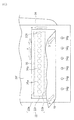
- FIG. 7 is a perspective view of the developer container in the embodiment of the present invention.
- FIG. 8 is a detailed view of the periphery of the discharge portion in the embodiment of the present invention.
- FIG. 9 is a detailed view of the configuration showing another positional relationship around the discharge portion in the embodiment of the present invention.
- FIG. 10 is a detailed view of another configuration in the embodiment of the present invention.
- FIG. 11 is a detailed view of another configuration that is not an embodiment of the present invention.
- FIG. 12 is a cross-sectional view of a developer storage unit that is not an embodiment of the present invention.
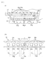
- FIG. 13 is a detailed view around the continuous discharge portion in the embodiment of the present invention.
- FIG. 14 is a detailed view of another joint configuration in the embodiment of the present invention.
- FIG. 15 is a perspective view of a conventional deformable container.
- FIG. 16 is a cross-sectional view for explaining the effect of the present invention.
- the developer storage container indicates at least a flexible container and a sealing member that seals an opening provided in the flexible container for discharging the developer.
- the developer storage unit includes at least a developer storage container and a frame that stores the developer storage container.
- FIG. 2 is a main sectional view of a process cartridge to which the present invention can be applied
- FIG. 3 is a main sectional view of an image forming apparatus to which the present invention can be applied.
- the process cartridge includes a photosensitive drum and process means acting on the photosensitive drum.
- the process means for example, a charging means for charging the surface of the photosensitive drum, a developing device for forming an image on the photosensitive drum, and a developer (including toner, carrier, etc.) remaining on the surface of the photosensitive drum are removed. There are cleaning means for. As shown in FIG.
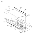
- the process cartridge A of this embodiment includes a charging roller 12 as charging means around a photosensitive drum 11, and a cleaner unit 24 having an elastic cleaning blade 14 as cleaning means. Further, the process cartridge A includes a developing device 38 having a first frame 17 and a second frame 18. In the process cartridge A, the cleaner unit 24 and the developing device 38 are integrated, and are configured to be detachable from the image forming apparatus main body B as shown in FIG.
- the developing device 38 as developing means includes a developing roller 13, a developing blade 15, a developer supply roller 23, a developer storage member 34 that is a flexible container for storing the developer, and a sealing member 19.
- a storage container 26 is provided. Hereinafter, it is referred to as a developer storage container 26.
- the developing roller 13 and the developing blade 15 are supported by the first frame 17.
- the process cartridge A is mounted on an image forming apparatus main body B as shown in FIG. 3 and used for image formation.
- a sheet S is conveyed by a conveyance roller 7 from a sheet cassette 6 mounted at the lower part of the image forming apparatus, and in synchronization with this sheet conveyance, the photosensitive drum 11 is selectively exposed from an exposure device 8 to be latent.
- the developer is supplied to the developing roller 13 (developer carrier) by a sponge-like developer supply roller 23 and is carried on the surface of the developing roller 13 by a developing blade 15.
- FIG. (Developer storage unit) As shown in FIG.
- the developer storage unit 25 includes a developer storage container 26, a developing roller 13, a developing blade 15, a first frame 17 that supports them, and a second frame 18. .
- a combination of the first frame 17 and the second frame 18 is a frame for storing the developer storage container 26.
- the developer storage unit 25 is the same as the developing device 38. This is because the developer storage unit 25 has the developing roller 13 and the developing blade 15. However, the developing roller 13 and the developing blade 15 may be supported by a separate frame from the developer storage unit 25 and separated from the developer storage unit 25.
- the developing device 38 includes the developer storage unit 25, the developing roller 13, and the developing blade 15. (Not shown) (Developer container) The configuration of the developer storage container will be described with reference to FIGS. As shown in FIG.
- the developer storage container 26 includes a developer storage member 34 and a sealing member 19.
- the developer accommodating member 34 is a flexible container that can accommodate a powdered developer therein.
- the developer accommodating member 34 includes a molding portion 34a formed by vacuum forming, pressure forming, or press molding of a sheet-like material, and a vent portion 34b having a sheet shape and air permeability.
- a method of joining the molding portion 34a and the ventilation portion 34b there are thermal welding, laser welding, adhesive, adhesive tape, and the like.
- a fixed portion 34g (fixed portion) of the developer storage member 34 is provided in part on the outer peripheral portion 34c of the developer storage member 34.
- the developer storage member 34 is provided with a discharge portion 35 that is an opening for discharging the developer.
- the sealing member 19 is joined to the developer storage member 34 so as to cover the discharge portion 35.
- the sealing member 19 is a flexible sheet-like member that is peeled off from the developer storage member 34 to expose the discharge portion 35 so that the developer can be discharged from the developer storage container 26. Can do.
- the sealing member 19 is connected to the opening member 20 by the engaged portion 19b, and the opening member 20 is rotatably supported by the second frame body 18.
- the unsealing member 20 is rotated in the direction of arrow C by driving force transmitted by a driving means (not shown) provided in the image forming apparatus main body B, thereby winding the sealing member 19 and exposing the discharge portion 35. It is possible. As shown in FIG.
- the developer storage container 26 is fixed to an internal space formed by the first frame body 17 and the second frame body 18 by a fixing portion 34g.
- the discharge unit 35 is configured to easily discharge the developer stored in the posture at the time of image formation. Therefore, the discharge unit 35 is arranged so as to face vertically downward in the posture during image formation. (Detailed configuration of the discharge unit)
- FIG. 8 is a detailed view of the periphery of the discharge portion 35 provided in the developer accommodating member 34. A state in which the sealing member 19 is bonded onto the developer accommodating member 34 is shown. The sealing member 19 seals the opening 35a and moves to expose the opening 35a.
- the moving direction of the sealing member 19 (the direction pulled by the opening member 20) is the direction D.
- the opening 35a is exposed in the opening direction E by the movement of the sealing member 19.
- the discharge unit 35 includes a plurality of openings 35a for discharging the internal developer, and a connecting portion 35b that defines the plurality of openings 35a.
- the opening 35 a and the connecting portion 35 b are arranged in a direction F perpendicular to the opening direction E.
- each of the plurality of openings 35a according to the first embodiment has a round shape.
- the discharge portion 35 is sealed by the sealing member 19 so that the periphery of the discharge portion 35 is continuously surrounded by the joint portion 22 and joined so as to be able to be opened and stored in the developer storage member 34.
- the joining portion 22 is discharged in a “round shape” shape in which two in the long direction (direction F) and two in the short direction (direction E) are continuously surrounded.
- the portion 35 can be sealed.
- the first joint portion 22a is opened first
- the second joint portion 22b is opened later.
- the joint portion 22 that faces the first joint portion 22a across the opening 35a is the second joint portion 22b.
- the short-direction joint 22 is referred to as a short joint 22c.
- the opening direction is the direction E.
- the opening direction is defined as follows.
- the first joint 22a is first opened (peeled) at the first joint 22a and the second joint 22b with the opening 35a interposed therebetween.
- the (Fixing of developer storage member and second frame) Next, fixing of the developer accommodating member 34 and the second frame 18 will be described with reference to FIGS. 4 and 7.
- the developer accommodating member 34 is fixed inside the second frame 18 by a fixing portion 34g.
- FIG. 4 the developer accommodating member 34 is fixed inside the second frame 18 by a fixing portion 34g.
- a plurality of fixing portions 34g are provided in parallel with the direction F in which the plurality of openings 35a are arranged, and receive a force when the sealing member 19 is opened from the developer storage member 34.
- the fixed part 34g may be one long in parallel with the direction F, other than being provided in this way.
- the fixing portion 34 g of the developer storage member 34 is fixed to the fixing portion 18 a of the second frame 18.
- means for fixing in addition to ultrasonic caulking, other than ultrasonic waves can be used.
- heat caulking using heat, heat welding or ultrasonic welding directly welding to the developer storage member 34 and the second frame 18, adhesion using a solvent or an adhesive, sandwiching between the frames, Thermal caulking, ultrasonic caulking, screws, hooks with holes and protrusions (bosses, etc.), etc. may be used.
- bonding a region where the developer storage member 34 and the second frame 18 are bonded is a fixing portion.
- pinching thermal caulking, ultrasonic caulking, screws, bosses, etc., the pinched area, the thermal caulking (ultrasonic caulking) area, and the area where screws, bosses, etc. are present are fixed parts. Become.
- the 2nd junction part 22b of the developer accommodating member 34 and the 2nd frame 18 are fixed.
- the following arrangement relationship is preferable between the portions 18a. That is, it is preferable that the fixing portion 18 a of the second frame 18 and the opening member 20 are provided so as to sandwich the discharge portion 35 in the moving direction D of the sealing member 19 by the opening member 20.
- the sealing member 19 is pulled by the opening member 20 in the direction of the arrow D with respect to the fixing portion 18a of the second frame 18 at the time of opening.
- the fixing portion 34 g of the developer accommodating member 34 is fixed by the fixing portion 18 a of the second frame 18.
- the sealing member 19 is pulled in the directions of arrows H and D between the fixing portion 18a of the second frame 18 and the opening member 20.
- a force is applied to the first joint portion 22a of the developer accommodating member 34, and the sealing member 19 is peeled in the direction of arrow E. Therefore, it is preferable that the discharge portion 35 is provided so as to be sandwiched by the opening member 20 and the fixing portion 18 a of the second frame 18 in the moving direction D of the sealing member 19.
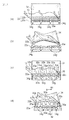
- FIG. 1 is a detailed view of the periphery of the discharge portion 35 when the opening portion 35a is exposed after the peeling of the first joint portion 22a to be opened first, and the second joint of the developer accommodating member 34. It is the state which has not finished peeling of the part 22b.
- FIG. 5 is a cross-sectional view of the developer storage unit 25 in a state where the second joint 22b of the developer storage member 34 has not been peeled after the first joint 22a is peeled off.
- FIG. 6 is a cross-sectional view of the developer storage unit 25 after the second joint 22b is peeled off.
- the discharge part 35 has a plurality of openings 35a in the direction F perpendicular to the opening direction E in which the exposure of the openings 35a proceeds. Therefore, a plurality of connecting portions 35b are also arranged in the F direction.
- the relationship between the connecting portion 35b and the fixing portion 34g of the developer accommodating member 34 described above is as follows. As shown in FIG. 1, among the connecting portions 35b located near the center in the F direction of the discharge portion 35, one connecting portion 35b1 and the fixing portion 34g1 of the developer storage member 34 are in the opening direction E and are connected to the connecting portion 35b1.
- the fixing portion 34g1 and the connecting portion 35b1 are arranged to overlap each other.
- the connecting part 35b1 is connected to the fixing part 34g1 of the developer storage member 34 and the developer storage. It plays the role which connects the 2nd junction part 22b of the member 34.
- the fixing force 34g1 of the developer accommodating member 34 can receive the opening force of the second joint 22b of the developer accommodating member 34 via the connecting portion 35b.
- FIG. 9 is a detailed view of the periphery of the discharge portion just before the second joint portion 22b is peeled off.
- the force at the time of opening the second joint portion 22b is received by the fixing portion 34g of the developer accommodating member 34 through the connecting portion 35b.
- the center part 34g1C of the fixed part 34g1 that is the center part of the range of the width Q1 that receives the force is arranged so as to be located in the center part of the region L of the connecting part 35b1.
- FIG. 10 shows another configuration of the plurality of openings 35a, the connecting portion 35b, and the fixing portion 34g of the developer accommodating member 34.
- FIGS. 10 (a) and 10 (b) are arranged in a region sandwiching 22c.
- the fixing portion 34g2 of the developer storage member 34 is disposed in a region L2 that sandwiches the opening 35a at both ends in the F direction of the discharge portion 35 and the short joint portion 22c, and similarly, the developer storage member 34 is in the range L3.
- the fixed portion 34g3 is disposed.
- the fixing portions 34g2 and 34g3 of the developer storage member 34 and the second joint portion 22b of the developer storage member 34 are connected via the developer storage member 34 also near both ends in the F direction of the discharge portion 35. ing.
- a region sandwiched between the opening 35 a at the end of the plurality of openings 35 and the short joint 22 c is defined as an end connecting portion L 2 (L 3 ).
- the opening direction E it arrange
- the developer force is applied to the peeling between the part that becomes the trigger for opening the second joint 22b of the developer storage member 34 and the part that is finally peeled off. It is important that it is received by the fixing portion 34g of the storage member 34.
- the unsealing member 20 is reversed by the sealing member 19 in the direction D shown in FIG. Pulled on. Therefore, the opening member 20 that is supported at both ends by the second frame 18 is bent in the direction opposite to the direction D.
- the bending amount of the opening member 20 is the smallest in the vicinity of both ends near the place where the opening member 20 is supported in the direction F shown in FIG. 10A, and the opening member 20 is supported.
- the distance near the center is the largest.
- the opening timing of the sealing member 19 by the opening member 20 becomes late, so that the bending of the opening member 20 is large.
- the sealing member 19 between the unsealing member 20 and the first joint is slack and has a margin, and the first one where the unsealing member starts winding only winds up the slack of the sealing member 19. Because it becomes.
- the second joint portion 22b of the developer storage member 34 is peeled off in the vicinity of both ends where the bending of the unsealing member 20 is small, leading to the peeling, and the vicinity of the center where the bending of the unsealing member 20 is large is finally peeled off. Is done.
- the developer accommodating member 34 is greatly deformed in the vicinity of the edge that causes separation, the developer accommodating member 34 may be wound around the opening member 20 and the opening may not start in the first place. Further, since the opening force becomes large at the first stage where peeling starts, a larger force is required when the developer accommodating member 34 is deformed to become a state of shear peeling described later.
- the fixing portions 34g2 and 34g3 of the developer storage member 34 are installed in a range of regions L2 and L3 that sandwich the opening 35a at both ends in the F direction of the discharge portion 35 and the short joint portion 22c in the opening direction E. Yes. Further, when the peeling progresses and the opening progresses to the vicinity of the center in the F direction, the developer accommodating member 34 is greatly deformed. This is because all the joints in the region other than the central portion are peeled off, and the peeling force related to the developer containing member 34 is concentrated in the central portion. If the developer storage member 34 is greatly deformed, problems such as wrapping around the opening member 20 occur in the same manner.
- the fixing portion 34g1 of the developer storage member 34 is disposed in the vicinity of the center in the F direction of the discharge portion 35 in the region L in the direction F of the connecting portion 35b1 in the opening direction E.
- the sealing member 19 can be reliably peeled off.
- the connecting portion 35b1 and the fixing portion 34g1 are arranged so as to overlap each other in the center portion of the second joint portion 22b in the direction F perpendicular to the opening direction E.
- FIGS. 10C and 10D show another configuration of the plurality of openings 35 a, the connecting portion 35 b, and the fixing portion 34 g of the developer containing member 34.
- 10 (c) and 10 (d) show the range of the region L in the direction F of the connecting portion 35b in the opening direction E in which the exposure of the opening 35a proceeds through all of the plurality of fixing portions 34g of the developer storage member 34. It is the composition arranged in.
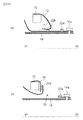
- FIG. 14A is an explanatory view of the periphery of the discharge portion 35 showing a bonding pattern of the bonding portion 22 that seals the opening 35a with the sealing member 19.
- FIG. 14B is an explanatory view around the discharge portion 35 showing the arrangement of the opening 35a.
- the joint portion 22 described above continuously surrounds the periphery of the opening 35a in a rectangular shape
- the following configuration may be used.
- the structure in which the periphery of each opening 35a is joined to the sealing member 19 and the developer storage member 34 by the joint 22 as shown in FIG. 14A, or the region of the joint 22 as shown in FIG. 14B.
- the openings 35a are also applied to a configuration in which the openings 35a are not completely aligned in a direction perpendicular to the opening direction E. Even in this case, when the fixing portion 34g of the developer storage member 34 is positioned in the region L of the connecting portion 35d when viewed from the opening direction E, the force for opening the joint portion 22 of the developer storage member 34 is connected.
- the fixing portion 34g of the developer accommodating member 34 can be received via the portion 35.
- the connecting portion 35 b can transmit the force for peeling the sealing member 19 from the developer accommodating member 34 to the fixing portion 34 g of the developer accommodating member 34. As a result, the sealing member 19 can be peeled even at the joint portion 22.
- FIG. 13 is an explanatory diagram in which the discharge portion 35 is configured by a connecting member 16f that is a separate member of the connecting portion 35b.
- FIG. 13A is an explanatory view of the periphery of the discharge portion 35 in which the discharge portion 35 is configured by a connection member 16f that is a separate member of the connection portion 35b
- FIG. 13B is an enlarged view thereof.
- a long opening 35a is provided in the direction F perpendicular to the opening direction E
- the fixing portion 34g of the developer containing member 34 is provided along the opening direction E in the long opening 35a.
- a second connecting member 16f that connects the second joint 22b of the developer accommodating member 34 is provided.
- the connecting member 16f is bonded to the first bonding portion 22a side and the second bonding portion 22b side of the long one opening 35a by bonding, welding, or the like.
- FIGS. 11A and FIG. 11B are configuration diagrams when the connecting portion 35b is not provided.
- FIGS. 11A and FIG. 11B are configuration diagrams when the connecting portion 35b is not provided.
- FIGS. 11C and 11D are configuration diagrams in the case where the fixing portion 34g of the developer storage member 34 is not arranged in the region of the connecting portion 35b in the opening direction E in which the exposure of the opening 35a proceeds. It is. 11A and 11C show the state before the second joint 22b of the developer containing member 34 is peeled off, and FIGS. 11B and 11D show the developer containing member. It is a figure of the state which has peeled 34 2nd junction part 22b. In this case, as shown in FIGS. 11 (a) and 11 (c), the sealing member 19 is moved to an arrow by the rotation of the opening member 20 from the state where the opening has advanced to the second joint 22 b of the developer accommodating member 34. It is pulled and moved in the direction of D.
- the second joining portion 22b of the developer accommodating member 34 loses the restraining force from the fixing portion 18a of the second frame 18, and the opening 35a is greatly opened in the direction of the arrow D. Further, the second joint 22b of the developer accommodating member 34 is pulled by the sealing member 19, and the opening 35a is deformed as shown in FIGS. 11B and 11D. In this case, the direction of the force acting on the second joint portion 22b of the developer accommodating member 34 is close to the direction of shear peeling. Therefore, a large force is required for peeling.
- the second joint portion 22b of the developer storage member 34 cannot be peeled off and is opened. It is pulled by 20. Therefore, the force from the fixing portion 34g of the developer storage member 34 cannot be transmitted to the second joint portion 22b side of the developer storage member 34.
- the opening 35 a in the vicinity of the longitudinal center of the second joint 22 b of the developer accommodating member 34 is further widened and is wound around the opening member 20. This will be described in detail with reference to FIG. Fig.16 (a) is a figure of A1-A2 cross section of FIG.10 (d).
- FIG. 16 (a) is sectional drawing of the part which a fixing
- FIG. 16B is a B1-B2 cross section of FIG.
- FIG. 16B is a cross-sectional view of a portion where the fixing portion and the connecting portion do not overlap in the opening direction that is not the configuration of the present invention.
- the frame 18 is illustrated for the purpose of explanation.
- FIG. 16A when the sealing member 19 is wound around the opening member, the developer accommodating member 34 is hardly deformed.
- the sealing member is peeled in a state where an angle ⁇ is formed between the surface of the sealing member 19 where the joint portion 22b is present and the surface where the sealing member 19 receives the force of the opening member 20.
- Inclined peeling On the other hand, in FIG. 16B, when the sealing member 19 is wound around the opening member, the portion in the vicinity of the opening 35 of the developer accommodating member 34 is deformed, and the angle ⁇ is approximately 0 °. In this state, the sealing member is peeled off (shear peeling). In the case of shear peeling, the force for opening becomes larger than that of inclined peeling, and there is a possibility that the opening cannot be performed. If the deformation of the flexible container is large, the flexible container may be wound around the shaft 20.
- the developer If the developer is stored as hard as a structure, it can be opened as in the prior art without such deformation. However, in the case where the developer is stored in a deformable soft bag and the opening 35a is deformed when opened, the connecting portion 35b exists, and the developer storage member 34 is fixed. The portion 34g is difficult to open unless it is disposed within the region of the connecting portion 35b. As described above, the fixing portion 34g of the developer accommodating member 34 is arranged in the range of the connecting portion 35b, so that the force that peels off the joining portion 22 between the sealing member 19 and the developer accommodating member 34 is not caused. The fixing portion 34g of the developer accommodating member 34 can be received via the connecting portion 35b. Therefore, the sealing member 19 of the developer accommodating member 34 can be reliably and stably opened.
Landscapes
- Physics & Mathematics (AREA)
- General Physics & Mathematics (AREA)
- Dry Development In Electrophotography (AREA)
- Closures For Containers (AREA)
Priority Applications (4)
| Application Number | Priority Date | Filing Date | Title |
|---|---|---|---|
| PH1/2014/500114A PH12014500114A1 (en) | 2011-07-14 | 2012-07-13 | Developer accommodating unit, process cartridge, electrophotographic image forming apparatus |
| EP12811743.9A EP2733546B1 (en) | 2011-07-14 | 2012-07-13 | Developer storage unit, process cartridge, and electrophotographic image forming device |
| CN201280034065.7A CN103649844B (zh) | 2011-07-14 | 2012-07-13 | 显影剂容纳单元、处理盒以及电子照相成像装置 |
| US13/951,663 US8824918B2 (en) | 2011-07-14 | 2013-07-26 | Developer accommodating unit, process cartridge, electrophotographic image forming apparatus |
Applications Claiming Priority (4)
| Application Number | Priority Date | Filing Date | Title |
|---|---|---|---|
| JP2011155834 | 2011-07-14 | ||
| JP2011-155834 | 2011-07-14 | ||
| JP2012-123490 | 2012-05-30 | ||
| JP2012123490A JP5959936B2 (ja) | 2011-07-14 | 2012-05-30 | 現像剤収納ユニット、プロセスカートリッジ、電子写真画像形成装置 |
Related Child Applications (1)
| Application Number | Title | Priority Date | Filing Date |
|---|---|---|---|
| US13/951,663 Continuation US8824918B2 (en) | 2011-07-14 | 2013-07-26 | Developer accommodating unit, process cartridge, electrophotographic image forming apparatus |
Publications (1)
| Publication Number | Publication Date |
|---|---|
| WO2013008952A1 true WO2013008952A1 (ja) | 2013-01-17 |
Family
ID=47506223
Family Applications (1)
| Application Number | Title | Priority Date | Filing Date |
|---|---|---|---|
| PCT/JP2012/068527 WO2013008952A1 (ja) | 2011-07-14 | 2012-07-13 | 現像剤収納ユニット、プロセスカートリッジ、電子写真画像形成装置 |
Country Status (6)
Families Citing this family (9)
| Publication number | Priority date | Publication date | Assignee | Title |
|---|---|---|---|---|
| PH12014500118A1 (en) * | 2011-07-14 | 2014-02-17 | Canon Kk | Developer accommodating unit, process cartridge, electrophotographic image forming apparatus |
| JP6116162B2 (ja) * | 2012-09-10 | 2017-04-19 | キヤノン株式会社 | 現像剤収容ユニット、現像装置、プロセスカートリッジ及び画像形成装置 |
| JP2015028594A (ja) * | 2013-06-24 | 2015-02-12 | キヤノン株式会社 | カートリッジ、プロセスカートリッジ及び画像形成装置 |
| JP6525662B2 (ja) * | 2015-03-27 | 2019-06-05 | キヤノン株式会社 | 現像剤容器、現像装置、プロセスカートリッジ、及び画像形成装置 |
| JP6604757B2 (ja) | 2015-06-30 | 2019-11-13 | キヤノン株式会社 | シール部材、ユニット及び画像形成装置 |
| JP6753112B2 (ja) * | 2016-03-31 | 2020-09-09 | ブラザー工業株式会社 | 現像剤カートリッジおよび現像剤収容ユニット |
| JP6766490B2 (ja) | 2016-07-14 | 2020-10-14 | ブラザー工業株式会社 | トナーカートリッジ |
| US10162288B2 (en) | 2016-09-23 | 2018-12-25 | Clover Technologies Group, Llc | System and method of remanufacturing a toner container |
| US9946199B1 (en) | 2016-09-23 | 2018-04-17 | Clover Technologies Group, Llc | System and method of filling a toner container |
Citations (7)
| Publication number | Priority date | Publication date | Assignee | Title |
|---|---|---|---|---|
| JPH0466980A (ja) | 1990-07-04 | 1992-03-03 | Canon Inc | 現像剤供給装置 |
| JPH05173419A (ja) * | 1991-02-25 | 1993-07-13 | Canon Inc | 現像剤供給装置及びプロセスカートリッジ |
| JPH05241447A (ja) * | 1992-03-03 | 1993-09-21 | Ricoh Co Ltd | 現像装置 |
| JPH096105A (ja) * | 1995-06-15 | 1997-01-10 | Canon Inc | プロセスカートリッジおよび現像装置およびトナーカートリッジおよび画像形成装置 |
| JPH09106156A (ja) * | 1995-10-09 | 1997-04-22 | Canon Inc | 現像剤容器、袋状シート及び現像剤充填装置 |
| JP2002169366A (ja) * | 2000-12-05 | 2002-06-14 | Canon Inc | プロセスカートリッジ |
| JP2003263014A (ja) * | 2002-03-07 | 2003-09-19 | Sharp Corp | トナー補給容器 |
Family Cites Families (6)
| Publication number | Priority date | Publication date | Assignee | Title |
|---|---|---|---|---|
| EP0736818A1 (en) | 1995-04-03 | 1996-10-09 | Canon Kabushiki Kaisha | Toner supply method, toner accommodation container, process cartridge and electrophotographic image forming apparatus |
| US5594535A (en) * | 1995-11-07 | 1997-01-14 | Hewlett-Packard Company | Refillable toner cartridge |
| JPH10143050A (ja) * | 1996-09-12 | 1998-05-29 | Canon Inc | プロセスカートリッジ、現像剤容器、残余現像剤容器、プロセスカートリッジの組立方法、プロセスカートリッジの現像剤再充填方法、プロセスカートリッジに用いられる支持枠体及び支持枠体の組立て方法 |
| US6763215B1 (en) * | 2001-06-27 | 2004-07-13 | Nu-Kote International, Inc. | Toner cartridge or cassette open/closure apparatus |
| JP2003228234A (ja) | 2002-02-01 | 2003-08-15 | Canon Inc | プロセスカートリッジ及び画像形成装置 |
| JP2011242757A (ja) | 2010-04-20 | 2011-12-01 | Canon Inc | 規制部材、クリーニング部材、現像装置、クリーニング装置、プロセスカートリッジ、及び画像形成装置 |
-
2012
- 2012-05-30 JP JP2012123490A patent/JP5959936B2/ja not_active Expired - Fee Related
- 2012-07-13 WO PCT/JP2012/068527 patent/WO2013008952A1/ja active Application Filing
- 2012-07-13 EP EP12811743.9A patent/EP2733546B1/en not_active Not-in-force
- 2012-07-13 PH PH1/2014/500114A patent/PH12014500114A1/en unknown
- 2012-07-13 CN CN201280034065.7A patent/CN103649844B/zh not_active Expired - Fee Related
-
2013
- 2013-07-26 US US13/951,663 patent/US8824918B2/en not_active Expired - Fee Related
Patent Citations (7)
| Publication number | Priority date | Publication date | Assignee | Title |
|---|---|---|---|---|
| JPH0466980A (ja) | 1990-07-04 | 1992-03-03 | Canon Inc | 現像剤供給装置 |
| JPH05173419A (ja) * | 1991-02-25 | 1993-07-13 | Canon Inc | 現像剤供給装置及びプロセスカートリッジ |
| JPH05241447A (ja) * | 1992-03-03 | 1993-09-21 | Ricoh Co Ltd | 現像装置 |
| JPH096105A (ja) * | 1995-06-15 | 1997-01-10 | Canon Inc | プロセスカートリッジおよび現像装置およびトナーカートリッジおよび画像形成装置 |
| JPH09106156A (ja) * | 1995-10-09 | 1997-04-22 | Canon Inc | 現像剤容器、袋状シート及び現像剤充填装置 |
| JP2002169366A (ja) * | 2000-12-05 | 2002-06-14 | Canon Inc | プロセスカートリッジ |
| JP2003263014A (ja) * | 2002-03-07 | 2003-09-19 | Sharp Corp | トナー補給容器 |
Non-Patent Citations (1)
| Title |
|---|
| See also references of EP2733546A4 |
Also Published As
| Publication number | Publication date |
|---|---|
| EP2733546A4 (en) | 2014-12-24 |
| EP2733546A1 (en) | 2014-05-21 |
| JP5959936B2 (ja) | 2016-08-02 |
| CN103649844A (zh) | 2014-03-19 |
| US8824918B2 (en) | 2014-09-02 |
| PH12014500114A1 (en) | 2022-11-23 |
| JP2013037341A (ja) | 2013-02-21 |
| CN103649844B (zh) | 2017-03-08 |
| EP2733546B1 (en) | 2018-09-12 |
| US20130308973A1 (en) | 2013-11-21 |
Similar Documents
| Publication | Publication Date | Title |
|---|---|---|
| JP5959936B2 (ja) | 現像剤収納ユニット、プロセスカートリッジ、電子写真画像形成装置 | |
| JP5675888B2 (ja) | 現像剤収納ユニット、現像装置、プロセスカートリッジ、画像形成装置 | |
| US8867955B2 (en) | Developer accommodating unit, process cartridge and electrophotographic image forming apparatus | |
| CN103649843B (zh) | 显影剂容纳容器、处理盒、电子照相型成像设备 | |
| US9304440B2 (en) | Developer accommodating unit, process cartridge and electrophotographic image forming apparatus | |
| US9291942B2 (en) | Developer accommodating unit, process cartridge and image forming apparatus | |
| US9354553B2 (en) | Developer accommodating container, process cartridge and electrophotographic image forming apparatus | |
| CN103688224B (zh) | 显影剂容纳单元、处理盒和电子照相成像设备 | |
| JP6282149B2 (ja) | 現像剤収納ユニット及び現像装置並びにプロセスカートリッジ、画像形成装置 | |
| JP6116253B2 (ja) | 現像剤収納ユニット、現像装置、プロセスカートリッジ及びこれらを備えた画像形成装置 | |
| JP6202820B2 (ja) | 現像剤収納ユニット、現像装置、プロセスカートリッジ、及び画像形成装置 | |
| CN103649845B (zh) | 显影剂容纳容器、显影剂容纳单元、处理盒、电子照相成像设备 | |
| JP6752596B2 (ja) | 現像剤容器、カートリッジ、及び画像形成装置 | |
| JP6095637B2 (ja) | 現像剤収納ユニット、現像装置、プロセスカートリッジ、画像形成装置 | |
| JP2014149473A (ja) | 現像剤収納ユニット、現像装置、プロセスカートリッジ、及び画像形成装置 | |
| JP2015200837A (ja) | 現像剤収納ユニット、プロセスカートリッジ及び画像形成装置 |
Legal Events
| Date | Code | Title | Description |
|---|---|---|---|
| 121 | Ep: the epo has been informed by wipo that ep was designated in this application |
Ref document number: 12811743 Country of ref document: EP Kind code of ref document: A1 |
|
| WWE | Wipo information: entry into national phase |
Ref document number: 2012811743 Country of ref document: EP |
|
| NENP | Non-entry into the national phase |
Ref country code: DE |