WO2013008952A1 - Developer storage unit, process cartridge, and electrophotographic image forming device - Google Patents
Developer storage unit, process cartridge, and electrophotographic image forming device Download PDFInfo
- Publication number
- WO2013008952A1 WO2013008952A1 PCT/JP2012/068527 JP2012068527W WO2013008952A1 WO 2013008952 A1 WO2013008952 A1 WO 2013008952A1 JP 2012068527 W JP2012068527 W JP 2012068527W WO 2013008952 A1 WO2013008952 A1 WO 2013008952A1
- Authority
- WO
- WIPO (PCT)
- Prior art keywords
- opening
- developer
- sealing member
- developer storage
- storage unit
- Prior art date
Links
Images


Classifications
-
- G—PHYSICS
- G03—PHOTOGRAPHY; CINEMATOGRAPHY; ANALOGOUS TECHNIQUES USING WAVES OTHER THAN OPTICAL WAVES; ELECTROGRAPHY; HOLOGRAPHY
- G03G—ELECTROGRAPHY; ELECTROPHOTOGRAPHY; MAGNETOGRAPHY
- G03G15/00—Apparatus for electrographic processes using a charge pattern
- G03G15/06—Apparatus for electrographic processes using a charge pattern for developing
- G03G15/08—Apparatus for electrographic processes using a charge pattern for developing using a solid developer, e.g. powder developer
- G03G15/0822—Arrangements for preparing, mixing, supplying or dispensing developer
- G03G15/0865—Arrangements for supplying new developer
- G03G15/0874—Arrangements for supplying new developer non-rigid containers, e.g. foldable cartridges, bags
-
- G—PHYSICS
- G03—PHOTOGRAPHY; CINEMATOGRAPHY; ANALOGOUS TECHNIQUES USING WAVES OTHER THAN OPTICAL WAVES; ELECTROGRAPHY; HOLOGRAPHY
- G03G—ELECTROGRAPHY; ELECTROPHOTOGRAPHY; MAGNETOGRAPHY
- G03G15/00—Apparatus for electrographic processes using a charge pattern
- G03G15/06—Apparatus for electrographic processes using a charge pattern for developing
- G03G15/08—Apparatus for electrographic processes using a charge pattern for developing using a solid developer, e.g. powder developer
- G03G15/0822—Arrangements for preparing, mixing, supplying or dispensing developer
- G03G15/0877—Arrangements for metering and dispensing developer from a developer cartridge into the development unit
- G03G15/0881—Sealing of developer cartridges
- G03G15/0882—Sealing of developer cartridges by a peelable sealing film
Definitions
- the present invention relates to an electrophotographic image forming apparatus, a developer storage unit used in the electrophotographic image forming apparatus, and a process cartridge.
- the electrophotographic image forming apparatus forms an image on a recording medium using, for example, an electrophotographic image forming process.
- an electrophotographic copying machine, an electrophotographic printer (for example, an LED printer, a laser beam printer, etc.), an electrophotographic facsimile machine, etc. are included (hereinafter referred to as an image forming apparatus).
- the process cartridge is an image forming apparatus main body in which a developing device is integrally configured so as to be detachable from the image forming apparatus main body, or a developing device and a photosensitive unit having at least a photoconductor. Says something that is removable.
- the developer storage container and the developer storage unit are stored in the image forming apparatus or the process cartridge.
- the developer storage container and the developer storage unit include at least a flexible container for storing the developer.
- an electrophotographic photosensitive member and process means acting on the electrophotographic photosensitive member are integrally formed into a cartridge, and the cartridge can be attached to and detached from the main body of the electrophotographic image forming apparatus.
- a cartridge system is adopted.
- the opening provided in the developer containing frame 31 for containing the developer (toner, carrier, etc.) is sealed with a sealing member.
- a method is widely employed in which the opening portion is opened by peeling the joint portion 33 of the toner seal 32 as a sealing member during use, so that the developer can be supplied (Japanese Patent Laid-Open No. 4-66980).
- an object of the present invention is to propose a developer storage unit using a flexible container and having an excellent unsealing property in a configuration different from the conventional one.
- One of the configurations of the invention according to the present application is as follows.
- the fixing portion and the connecting portion are arranged so as to overlap with each other.
- FIG. 1 is an explanatory diagram of a developer container in the embodiment of the present invention.
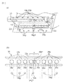
- FIG. 2 is a main sectional view of the process cartridge according to the embodiment of the present invention.
- FIG. 3 is a main cross-sectional view of the image forming apparatus in the embodiment of the present invention.
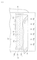
- FIG. 4 is a cross-sectional view of the developer storage unit in the embodiment of the present invention.
- FIG. 5 is a cross-sectional view of the developer storage unit in the embodiment of the present invention.
- FIG. 6 is a cross-sectional view of the developer storage unit in the embodiment of the present invention.
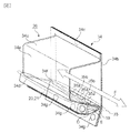
- FIG. 7 is a perspective view of the developer container in the embodiment of the present invention.
- FIG. 8 is a detailed view of the periphery of the discharge portion in the embodiment of the present invention.
- FIG. 9 is a detailed view of the configuration showing another positional relationship around the discharge portion in the embodiment of the present invention.
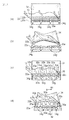
- FIG. 10 is a detailed view of another configuration in the embodiment of the present invention.
- FIG. 11 is a detailed view of another configuration that is not an embodiment of the present invention.
- FIG. 12 is a cross-sectional view of a developer storage unit that is not an embodiment of the present invention.
- FIG. 13 is a detailed view around the continuous discharge portion in the embodiment of the present invention.
- FIG. 14 is a detailed view of another joint configuration in the embodiment of the present invention.
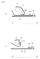
- FIG. 15 is a perspective view of a conventional deformable container.
- FIG. 16 is a cross-sectional view for explaining the effect of the present invention.
- the developer storage container indicates at least a flexible container and a sealing member that seals an opening provided in the flexible container for discharging the developer.
- the developer storage unit includes at least a developer storage container and a frame that stores the developer storage container.
- FIG. 2 is a main sectional view of a process cartridge to which the present invention can be applied
- FIG. 3 is a main sectional view of an image forming apparatus to which the present invention can be applied.
- the process cartridge includes a photosensitive drum and process means acting on the photosensitive drum.
- the process means for example, a charging means for charging the surface of the photosensitive drum, a developing device for forming an image on the photosensitive drum, and a developer (including toner, carrier, etc.) remaining on the surface of the photosensitive drum are removed. There are cleaning means for. As shown in FIG.
- the process cartridge A of this embodiment includes a charging roller 12 as charging means around a photosensitive drum 11, and a cleaner unit 24 having an elastic cleaning blade 14 as cleaning means. Further, the process cartridge A includes a developing device 38 having a first frame 17 and a second frame 18. In the process cartridge A, the cleaner unit 24 and the developing device 38 are integrated, and are configured to be detachable from the image forming apparatus main body B as shown in FIG.
- the developing device 38 as developing means includes a developing roller 13, a developing blade 15, a developer supply roller 23, a developer storage member 34 that is a flexible container for storing the developer, and a sealing member 19.
- a storage container 26 is provided. Hereinafter, it is referred to as a developer storage container 26.
- the developing roller 13 and the developing blade 15 are supported by the first frame 17.
- the process cartridge A is mounted on an image forming apparatus main body B as shown in FIG. 3 and used for image formation.
- a sheet S is conveyed by a conveyance roller 7 from a sheet cassette 6 mounted at the lower part of the image forming apparatus, and in synchronization with this sheet conveyance, the photosensitive drum 11 is selectively exposed from an exposure device 8 to be latent.
- the developer is supplied to the developing roller 13 (developer carrier) by a sponge-like developer supply roller 23 and is carried on the surface of the developing roller 13 by a developing blade 15.
- FIG. (Developer storage unit) As shown in FIG.
- the developer storage unit 25 includes a developer storage container 26, a developing roller 13, a developing blade 15, a first frame 17 that supports them, and a second frame 18. .
- a combination of the first frame 17 and the second frame 18 is a frame for storing the developer storage container 26.
- the developer storage unit 25 is the same as the developing device 38. This is because the developer storage unit 25 has the developing roller 13 and the developing blade 15. However, the developing roller 13 and the developing blade 15 may be supported by a separate frame from the developer storage unit 25 and separated from the developer storage unit 25.
- the developing device 38 includes the developer storage unit 25, the developing roller 13, and the developing blade 15. (Not shown) (Developer container) The configuration of the developer storage container will be described with reference to FIGS. As shown in FIG.
- the developer storage container 26 includes a developer storage member 34 and a sealing member 19.
- the developer accommodating member 34 is a flexible container that can accommodate a powdered developer therein.
- the developer accommodating member 34 includes a molding portion 34a formed by vacuum forming, pressure forming, or press molding of a sheet-like material, and a vent portion 34b having a sheet shape and air permeability.
- a method of joining the molding portion 34a and the ventilation portion 34b there are thermal welding, laser welding, adhesive, adhesive tape, and the like.
- a fixed portion 34g (fixed portion) of the developer storage member 34 is provided in part on the outer peripheral portion 34c of the developer storage member 34.
- the developer storage member 34 is provided with a discharge portion 35 that is an opening for discharging the developer.
- the sealing member 19 is joined to the developer storage member 34 so as to cover the discharge portion 35.
- the sealing member 19 is a flexible sheet-like member that is peeled off from the developer storage member 34 to expose the discharge portion 35 so that the developer can be discharged from the developer storage container 26. Can do.
- the sealing member 19 is connected to the opening member 20 by the engaged portion 19b, and the opening member 20 is rotatably supported by the second frame body 18.
- the unsealing member 20 is rotated in the direction of arrow C by driving force transmitted by a driving means (not shown) provided in the image forming apparatus main body B, thereby winding the sealing member 19 and exposing the discharge portion 35. It is possible. As shown in FIG.
- the developer storage container 26 is fixed to an internal space formed by the first frame body 17 and the second frame body 18 by a fixing portion 34g.
- the discharge unit 35 is configured to easily discharge the developer stored in the posture at the time of image formation. Therefore, the discharge unit 35 is arranged so as to face vertically downward in the posture during image formation. (Detailed configuration of the discharge unit)
- FIG. 8 is a detailed view of the periphery of the discharge portion 35 provided in the developer accommodating member 34. A state in which the sealing member 19 is bonded onto the developer accommodating member 34 is shown. The sealing member 19 seals the opening 35a and moves to expose the opening 35a.
- the moving direction of the sealing member 19 (the direction pulled by the opening member 20) is the direction D.
- the opening 35a is exposed in the opening direction E by the movement of the sealing member 19.
- the discharge unit 35 includes a plurality of openings 35a for discharging the internal developer, and a connecting portion 35b that defines the plurality of openings 35a.
- the opening 35 a and the connecting portion 35 b are arranged in a direction F perpendicular to the opening direction E.
- each of the plurality of openings 35a according to the first embodiment has a round shape.
- the discharge portion 35 is sealed by the sealing member 19 so that the periphery of the discharge portion 35 is continuously surrounded by the joint portion 22 and joined so as to be able to be opened and stored in the developer storage member 34.
- the joining portion 22 is discharged in a “round shape” shape in which two in the long direction (direction F) and two in the short direction (direction E) are continuously surrounded.
- the portion 35 can be sealed.
- the first joint portion 22a is opened first
- the second joint portion 22b is opened later.
- the joint portion 22 that faces the first joint portion 22a across the opening 35a is the second joint portion 22b.
- the short-direction joint 22 is referred to as a short joint 22c.
- the opening direction is the direction E.
- the opening direction is defined as follows.
- the first joint 22a is first opened (peeled) at the first joint 22a and the second joint 22b with the opening 35a interposed therebetween.
- the (Fixing of developer storage member and second frame) Next, fixing of the developer accommodating member 34 and the second frame 18 will be described with reference to FIGS. 4 and 7.
- the developer accommodating member 34 is fixed inside the second frame 18 by a fixing portion 34g.
- FIG. 4 the developer accommodating member 34 is fixed inside the second frame 18 by a fixing portion 34g.
- a plurality of fixing portions 34g are provided in parallel with the direction F in which the plurality of openings 35a are arranged, and receive a force when the sealing member 19 is opened from the developer storage member 34.
- the fixed part 34g may be one long in parallel with the direction F, other than being provided in this way.
- the fixing portion 34 g of the developer storage member 34 is fixed to the fixing portion 18 a of the second frame 18.
- means for fixing in addition to ultrasonic caulking, other than ultrasonic waves can be used.
- heat caulking using heat, heat welding or ultrasonic welding directly welding to the developer storage member 34 and the second frame 18, adhesion using a solvent or an adhesive, sandwiching between the frames, Thermal caulking, ultrasonic caulking, screws, hooks with holes and protrusions (bosses, etc.), etc. may be used.
- bonding a region where the developer storage member 34 and the second frame 18 are bonded is a fixing portion.
- pinching thermal caulking, ultrasonic caulking, screws, bosses, etc., the pinched area, the thermal caulking (ultrasonic caulking) area, and the area where screws, bosses, etc. are present are fixed parts. Become.
- the 2nd junction part 22b of the developer accommodating member 34 and the 2nd frame 18 are fixed.
- the following arrangement relationship is preferable between the portions 18a. That is, it is preferable that the fixing portion 18 a of the second frame 18 and the opening member 20 are provided so as to sandwich the discharge portion 35 in the moving direction D of the sealing member 19 by the opening member 20.
- the sealing member 19 is pulled by the opening member 20 in the direction of the arrow D with respect to the fixing portion 18a of the second frame 18 at the time of opening.
- the fixing portion 34 g of the developer accommodating member 34 is fixed by the fixing portion 18 a of the second frame 18.
- the sealing member 19 is pulled in the directions of arrows H and D between the fixing portion 18a of the second frame 18 and the opening member 20.
- a force is applied to the first joint portion 22a of the developer accommodating member 34, and the sealing member 19 is peeled in the direction of arrow E. Therefore, it is preferable that the discharge portion 35 is provided so as to be sandwiched by the opening member 20 and the fixing portion 18 a of the second frame 18 in the moving direction D of the sealing member 19.
- FIG. 1 is a detailed view of the periphery of the discharge portion 35 when the opening portion 35a is exposed after the peeling of the first joint portion 22a to be opened first, and the second joint of the developer accommodating member 34. It is the state which has not finished peeling of the part 22b.
- FIG. 5 is a cross-sectional view of the developer storage unit 25 in a state where the second joint 22b of the developer storage member 34 has not been peeled after the first joint 22a is peeled off.
- FIG. 6 is a cross-sectional view of the developer storage unit 25 after the second joint 22b is peeled off.
- the discharge part 35 has a plurality of openings 35a in the direction F perpendicular to the opening direction E in which the exposure of the openings 35a proceeds. Therefore, a plurality of connecting portions 35b are also arranged in the F direction.
- the relationship between the connecting portion 35b and the fixing portion 34g of the developer accommodating member 34 described above is as follows. As shown in FIG. 1, among the connecting portions 35b located near the center in the F direction of the discharge portion 35, one connecting portion 35b1 and the fixing portion 34g1 of the developer storage member 34 are in the opening direction E and are connected to the connecting portion 35b1.
- the fixing portion 34g1 and the connecting portion 35b1 are arranged to overlap each other.
- the connecting part 35b1 is connected to the fixing part 34g1 of the developer storage member 34 and the developer storage. It plays the role which connects the 2nd junction part 22b of the member 34.
- the fixing force 34g1 of the developer accommodating member 34 can receive the opening force of the second joint 22b of the developer accommodating member 34 via the connecting portion 35b.
- FIG. 9 is a detailed view of the periphery of the discharge portion just before the second joint portion 22b is peeled off.
- the force at the time of opening the second joint portion 22b is received by the fixing portion 34g of the developer accommodating member 34 through the connecting portion 35b.
- the center part 34g1C of the fixed part 34g1 that is the center part of the range of the width Q1 that receives the force is arranged so as to be located in the center part of the region L of the connecting part 35b1.
- FIG. 10 shows another configuration of the plurality of openings 35a, the connecting portion 35b, and the fixing portion 34g of the developer accommodating member 34.
- FIGS. 10 (a) and 10 (b) are arranged in a region sandwiching 22c.
- the fixing portion 34g2 of the developer storage member 34 is disposed in a region L2 that sandwiches the opening 35a at both ends in the F direction of the discharge portion 35 and the short joint portion 22c, and similarly, the developer storage member 34 is in the range L3.
- the fixed portion 34g3 is disposed.
- the fixing portions 34g2 and 34g3 of the developer storage member 34 and the second joint portion 22b of the developer storage member 34 are connected via the developer storage member 34 also near both ends in the F direction of the discharge portion 35. ing.
- a region sandwiched between the opening 35 a at the end of the plurality of openings 35 and the short joint 22 c is defined as an end connecting portion L 2 (L 3 ).
- the opening direction E it arrange
- the developer force is applied to the peeling between the part that becomes the trigger for opening the second joint 22b of the developer storage member 34 and the part that is finally peeled off. It is important that it is received by the fixing portion 34g of the storage member 34.
- the unsealing member 20 is reversed by the sealing member 19 in the direction D shown in FIG. Pulled on. Therefore, the opening member 20 that is supported at both ends by the second frame 18 is bent in the direction opposite to the direction D.
- the bending amount of the opening member 20 is the smallest in the vicinity of both ends near the place where the opening member 20 is supported in the direction F shown in FIG. 10A, and the opening member 20 is supported.
- the distance near the center is the largest.
- the opening timing of the sealing member 19 by the opening member 20 becomes late, so that the bending of the opening member 20 is large.
- the sealing member 19 between the unsealing member 20 and the first joint is slack and has a margin, and the first one where the unsealing member starts winding only winds up the slack of the sealing member 19. Because it becomes.
- the second joint portion 22b of the developer storage member 34 is peeled off in the vicinity of both ends where the bending of the unsealing member 20 is small, leading to the peeling, and the vicinity of the center where the bending of the unsealing member 20 is large is finally peeled off. Is done.
- the developer accommodating member 34 is greatly deformed in the vicinity of the edge that causes separation, the developer accommodating member 34 may be wound around the opening member 20 and the opening may not start in the first place. Further, since the opening force becomes large at the first stage where peeling starts, a larger force is required when the developer accommodating member 34 is deformed to become a state of shear peeling described later.
- the fixing portions 34g2 and 34g3 of the developer storage member 34 are installed in a range of regions L2 and L3 that sandwich the opening 35a at both ends in the F direction of the discharge portion 35 and the short joint portion 22c in the opening direction E. Yes. Further, when the peeling progresses and the opening progresses to the vicinity of the center in the F direction, the developer accommodating member 34 is greatly deformed. This is because all the joints in the region other than the central portion are peeled off, and the peeling force related to the developer containing member 34 is concentrated in the central portion. If the developer storage member 34 is greatly deformed, problems such as wrapping around the opening member 20 occur in the same manner.
- the fixing portion 34g1 of the developer storage member 34 is disposed in the vicinity of the center in the F direction of the discharge portion 35 in the region L in the direction F of the connecting portion 35b1 in the opening direction E.
- the sealing member 19 can be reliably peeled off.
- the connecting portion 35b1 and the fixing portion 34g1 are arranged so as to overlap each other in the center portion of the second joint portion 22b in the direction F perpendicular to the opening direction E.
- FIGS. 10C and 10D show another configuration of the plurality of openings 35 a, the connecting portion 35 b, and the fixing portion 34 g of the developer containing member 34.
- 10 (c) and 10 (d) show the range of the region L in the direction F of the connecting portion 35b in the opening direction E in which the exposure of the opening 35a proceeds through all of the plurality of fixing portions 34g of the developer storage member 34. It is the composition arranged in.
- FIG. 14A is an explanatory view of the periphery of the discharge portion 35 showing a bonding pattern of the bonding portion 22 that seals the opening 35a with the sealing member 19.
- FIG. 14B is an explanatory view around the discharge portion 35 showing the arrangement of the opening 35a.
- the joint portion 22 described above continuously surrounds the periphery of the opening 35a in a rectangular shape
- the following configuration may be used.
- the structure in which the periphery of each opening 35a is joined to the sealing member 19 and the developer storage member 34 by the joint 22 as shown in FIG. 14A, or the region of the joint 22 as shown in FIG. 14B.
- the openings 35a are also applied to a configuration in which the openings 35a are not completely aligned in a direction perpendicular to the opening direction E. Even in this case, when the fixing portion 34g of the developer storage member 34 is positioned in the region L of the connecting portion 35d when viewed from the opening direction E, the force for opening the joint portion 22 of the developer storage member 34 is connected.
- the fixing portion 34g of the developer accommodating member 34 can be received via the portion 35.
- the connecting portion 35 b can transmit the force for peeling the sealing member 19 from the developer accommodating member 34 to the fixing portion 34 g of the developer accommodating member 34. As a result, the sealing member 19 can be peeled even at the joint portion 22.
- FIG. 13 is an explanatory diagram in which the discharge portion 35 is configured by a connecting member 16f that is a separate member of the connecting portion 35b.
- FIG. 13A is an explanatory view of the periphery of the discharge portion 35 in which the discharge portion 35 is configured by a connection member 16f that is a separate member of the connection portion 35b
- FIG. 13B is an enlarged view thereof.
- a long opening 35a is provided in the direction F perpendicular to the opening direction E
- the fixing portion 34g of the developer containing member 34 is provided along the opening direction E in the long opening 35a.
- a second connecting member 16f that connects the second joint 22b of the developer accommodating member 34 is provided.
- the connecting member 16f is bonded to the first bonding portion 22a side and the second bonding portion 22b side of the long one opening 35a by bonding, welding, or the like.
- FIGS. 11A and FIG. 11B are configuration diagrams when the connecting portion 35b is not provided.
- FIGS. 11A and FIG. 11B are configuration diagrams when the connecting portion 35b is not provided.
- FIGS. 11C and 11D are configuration diagrams in the case where the fixing portion 34g of the developer storage member 34 is not arranged in the region of the connecting portion 35b in the opening direction E in which the exposure of the opening 35a proceeds. It is. 11A and 11C show the state before the second joint 22b of the developer containing member 34 is peeled off, and FIGS. 11B and 11D show the developer containing member. It is a figure of the state which has peeled 34 2nd junction part 22b. In this case, as shown in FIGS. 11 (a) and 11 (c), the sealing member 19 is moved to an arrow by the rotation of the opening member 20 from the state where the opening has advanced to the second joint 22 b of the developer accommodating member 34. It is pulled and moved in the direction of D.
- the second joining portion 22b of the developer accommodating member 34 loses the restraining force from the fixing portion 18a of the second frame 18, and the opening 35a is greatly opened in the direction of the arrow D. Further, the second joint 22b of the developer accommodating member 34 is pulled by the sealing member 19, and the opening 35a is deformed as shown in FIGS. 11B and 11D. In this case, the direction of the force acting on the second joint portion 22b of the developer accommodating member 34 is close to the direction of shear peeling. Therefore, a large force is required for peeling.
- the second joint portion 22b of the developer storage member 34 cannot be peeled off and is opened. It is pulled by 20. Therefore, the force from the fixing portion 34g of the developer storage member 34 cannot be transmitted to the second joint portion 22b side of the developer storage member 34.
- the opening 35 a in the vicinity of the longitudinal center of the second joint 22 b of the developer accommodating member 34 is further widened and is wound around the opening member 20. This will be described in detail with reference to FIG. Fig.16 (a) is a figure of A1-A2 cross section of FIG.10 (d).
- FIG. 16 (a) is sectional drawing of the part which a fixing
- FIG. 16B is a B1-B2 cross section of FIG.
- FIG. 16B is a cross-sectional view of a portion where the fixing portion and the connecting portion do not overlap in the opening direction that is not the configuration of the present invention.
- the frame 18 is illustrated for the purpose of explanation.
- FIG. 16A when the sealing member 19 is wound around the opening member, the developer accommodating member 34 is hardly deformed.
- the sealing member is peeled in a state where an angle ⁇ is formed between the surface of the sealing member 19 where the joint portion 22b is present and the surface where the sealing member 19 receives the force of the opening member 20.
- Inclined peeling On the other hand, in FIG. 16B, when the sealing member 19 is wound around the opening member, the portion in the vicinity of the opening 35 of the developer accommodating member 34 is deformed, and the angle ⁇ is approximately 0 °. In this state, the sealing member is peeled off (shear peeling). In the case of shear peeling, the force for opening becomes larger than that of inclined peeling, and there is a possibility that the opening cannot be performed. If the deformation of the flexible container is large, the flexible container may be wound around the shaft 20.
- the developer If the developer is stored as hard as a structure, it can be opened as in the prior art without such deformation. However, in the case where the developer is stored in a deformable soft bag and the opening 35a is deformed when opened, the connecting portion 35b exists, and the developer storage member 34 is fixed. The portion 34g is difficult to open unless it is disposed within the region of the connecting portion 35b. As described above, the fixing portion 34g of the developer accommodating member 34 is arranged in the range of the connecting portion 35b, so that the force that peels off the joining portion 22 between the sealing member 19 and the developer accommodating member 34 is not caused. The fixing portion 34g of the developer accommodating member 34 can be received via the connecting portion 35b. Therefore, the sealing member 19 of the developer accommodating member 34 can be reliably and stably opened.
Abstract
A fixation section (34g) of a developer storage member (34) is disposed within the region of a connection section (35b) of a discharge part (35) in an unsealing direction in which the exposure of the discharge part (35) progresses.
Description
本発明は、電子写真画像形成装置、および電子写真画像形成装置に用いられる現像剤収納ユニット、プロセスカートリッジに関するものである。
ここで電子写真画像形成装置とは、例えば電子写真画像形成プロセスを用いて記録媒体に画像を形成するものである。例えば電子写真複写機、電子写真プリンター(例えば、LEDプリンター、レーザービームプリンタ等)、電子写真ファクシミリ装置等が含まれる(以後、画像形成装置と呼ぶ)。
また、プロセスカートリッジとは、現像装置を一体的に構成して画像形成装置本体に着脱可能にしたものや、現像装置と少なくとも感光体を有する感光体ユニットを一体的に構成して画像形成装置本体に着脱可能にしたものを言う。
また、現像剤収納容器および現像剤収納ユニットは、前記画像形成装置または前記プロセスカートリッジに収納されるものである。現像剤収納容器及び現像剤収納ユニットは、少なくとも現像剤を収納するための可撓性容器を備えている。 The present invention relates to an electrophotographic image forming apparatus, a developer storage unit used in the electrophotographic image forming apparatus, and a process cartridge.
Here, the electrophotographic image forming apparatus forms an image on a recording medium using, for example, an electrophotographic image forming process. For example, an electrophotographic copying machine, an electrophotographic printer (for example, an LED printer, a laser beam printer, etc.), an electrophotographic facsimile machine, etc. are included (hereinafter referred to as an image forming apparatus).
Further, the process cartridge is an image forming apparatus main body in which a developing device is integrally configured so as to be detachable from the image forming apparatus main body, or a developing device and a photosensitive unit having at least a photoconductor. Says something that is removable.
The developer storage container and the developer storage unit are stored in the image forming apparatus or the process cartridge. The developer storage container and the developer storage unit include at least a flexible container for storing the developer.
従来の電子写真形成プロセスを用いた電子写真画像形成装置には、電子写真感光体及びそれに作用するプロセス手段を一体的にカートリッジ化して、このカートリッジを電子写真画像形成装置本体に着脱可能とするプロセスカートリッジ方式が採用されている。
このようなプロセスカートリッジでは、図15で示す様に現像剤(トナー、キャリア等)を収納する現像剤収納枠体31に設けた開口部を封止部材で封止している。そして、使用時に封止部材であるトナーシール32の接合部33を引き剥がすことで開口部が開封され現像剤の供給が可能となる方式が広く採用されている(特開平4−66980)。
またプロセスカートリッジ製造時に現像剤の充填工程でプロセスカートリッジの機内に現像剤が飛散する問題に対して変形可能な内部容器を用いたものが考案されている。そして、変形可能な内部容器の内側に弾性部材を設け、開封部材での開封後に開口が大きく開くように構成している。(特開平4−66980)。 In a conventional electrophotographic image forming apparatus using an electrophotographic image forming process, an electrophotographic photosensitive member and process means acting on the electrophotographic photosensitive member are integrally formed into a cartridge, and the cartridge can be attached to and detached from the main body of the electrophotographic image forming apparatus. A cartridge system is adopted.
In such a process cartridge, as shown in FIG. 15, the opening provided in thedeveloper containing frame 31 for containing the developer (toner, carrier, etc.) is sealed with a sealing member. A method is widely employed in which the opening portion is opened by peeling the joint portion 33 of the toner seal 32 as a sealing member during use, so that the developer can be supplied (Japanese Patent Laid-Open No. 4-66980).
In addition, there has been devised an apparatus using a deformable inner container for the problem that the developer is scattered in the process cartridge in the developer filling process at the time of manufacturing the process cartridge. Then, an elastic member is provided inside the deformable inner container so that the opening is greatly opened after opening with the opening member. (Japanese Patent Laid-Open No. 4-66980).
このようなプロセスカートリッジでは、図15で示す様に現像剤(トナー、キャリア等)を収納する現像剤収納枠体31に設けた開口部を封止部材で封止している。そして、使用時に封止部材であるトナーシール32の接合部33を引き剥がすことで開口部が開封され現像剤の供給が可能となる方式が広く採用されている(特開平4−66980)。
またプロセスカートリッジ製造時に現像剤の充填工程でプロセスカートリッジの機内に現像剤が飛散する問題に対して変形可能な内部容器を用いたものが考案されている。そして、変形可能な内部容器の内側に弾性部材を設け、開封部材での開封後に開口が大きく開くように構成している。(特開平4−66980)。 In a conventional electrophotographic image forming apparatus using an electrophotographic image forming process, an electrophotographic photosensitive member and process means acting on the electrophotographic photosensitive member are integrally formed into a cartridge, and the cartridge can be attached to and detached from the main body of the electrophotographic image forming apparatus. A cartridge system is adopted.
In such a process cartridge, as shown in FIG. 15, the opening provided in the
In addition, there has been devised an apparatus using a deformable inner container for the problem that the developer is scattered in the process cartridge in the developer filling process at the time of manufacturing the process cartridge. Then, an elastic member is provided inside the deformable inner container so that the opening is greatly opened after opening with the opening member. (Japanese Patent Laid-Open No. 4-66980).
しかし特開平4−66980のように、内部容器の内側に弾性部材を設けることは製造上困難であり、またコストがかかってしまうと場合がある。
そこで本発明の目的は、従来とは異なる構成において、可撓性容器を用いた現像剤収納ユニットであって、開封性の優れた現像剤収納ユニットを提案するものである。
本出願に係る発明の構成の一つは以下のようなものである。
画像形成に用いられる現像剤を収納する現像剤収納ユニットであって、収納した現像剤を排出するための開口部を備えた可撓性容器と、前記開口部を接合部により封止するとともに移動されることによって前記開口部を露出する封止部材と、を有する現像剤収納容器と、前記封止部材に取り付けられ、前記封止部材を移動させる開封部材と前記現像剤収納容器と前記開封部材とを収納し、前記可撓性容器を固定する固定部を有する枠体とを備え、複数の前記開口部の、開口部と開口部の間の部分を連結部として、前記封止部材の開封方向において、前記固定部と前記連結部とはオーバーラップするように配置されていることを特徴とする現像剤収納ユニットである。
本発明によれば、従来とは異なる構成において、可撓性容器を用いた現像剤収納ユニットであって、開封性の優れた現像剤収納ユニットを提供することができる。 However, as disclosed in Japanese Patent Laid-Open No. 4-66980, it is difficult to manufacture an elastic member inside the inner container, and it may be costly.
SUMMARY OF THE INVENTION Accordingly, an object of the present invention is to propose a developer storage unit using a flexible container and having an excellent unsealing property in a configuration different from the conventional one.
One of the configurations of the invention according to the present application is as follows.
A developer storage unit for storing a developer used for image formation, the flexible container having an opening for discharging the stored developer, and the opening being sealed and moved by a joint A developer storage container having a sealing member that exposes the opening, and an opening member attached to the sealing member to move the sealing member, the developer storage container, and the opening member And a frame body having a fixing portion for fixing the flexible container, and opening the sealing member with a portion between the openings as a connecting portion. In the direction, the fixing portion and the connecting portion are arranged so as to overlap with each other.
According to the present invention, it is possible to provide a developer storage unit using a flexible container and having an excellent unsealing property in a configuration different from the conventional one.
図1は本発明の実施の形態における現像剤収納容器の説明図である。
図2は本発明の実施の形態におけるプロセスカートリッジの主断面図である。
図3は本発明の実施の形態における画像形成装置の主断面図である。
図4は本発明の実施の形態における現像剤収納ユニットの断面図である。
図5は本発明の実施の形態における現像剤収納ユニットの断面図である。
図6は本発明の実施の形態における現像剤収納ユニットの断面図である。
図7は本発明の実施の形態における現像剤収納容器の斜視図である。
図8は本発明の実施の形態における排出部周辺の詳細図である。
図9は本発明の実施の形態における排出部周辺の他の位置関係を示す構成の詳細図である。
図10は本発明の実施の形態における他の構成の詳細図である。
図11は本発明の実施の形態ではない他の構成の詳細図である。
図12は本発明の実施の形態ではない現像剤収納ユニットの断面図である。
図13は本発明の実施の形態における連排出部周辺の詳細図である。
図14は本発明の実施の形態における他の接合部構成の詳細図である。
図15は従来の変形可能な容器の斜視図である。
図16は本発明の効果を説明するための断面図である。 FIG. 1 is an explanatory diagram of a developer container in the embodiment of the present invention.
FIG. 2 is a main sectional view of the process cartridge according to the embodiment of the present invention.
FIG. 3 is a main cross-sectional view of the image forming apparatus in the embodiment of the present invention.
FIG. 4 is a cross-sectional view of the developer storage unit in the embodiment of the present invention.
FIG. 5 is a cross-sectional view of the developer storage unit in the embodiment of the present invention.
FIG. 6 is a cross-sectional view of the developer storage unit in the embodiment of the present invention.
FIG. 7 is a perspective view of the developer container in the embodiment of the present invention.
FIG. 8 is a detailed view of the periphery of the discharge portion in the embodiment of the present invention.
FIG. 9 is a detailed view of the configuration showing another positional relationship around the discharge portion in the embodiment of the present invention.
FIG. 10 is a detailed view of another configuration in the embodiment of the present invention.
FIG. 11 is a detailed view of another configuration that is not an embodiment of the present invention.
FIG. 12 is a cross-sectional view of a developer storage unit that is not an embodiment of the present invention.
FIG. 13 is a detailed view around the continuous discharge portion in the embodiment of the present invention.
FIG. 14 is a detailed view of another joint configuration in the embodiment of the present invention.
FIG. 15 is a perspective view of a conventional deformable container.
FIG. 16 is a cross-sectional view for explaining the effect of the present invention.
現像剤収納容器は、少なくとも、可撓性容器と可撓性容器に設けられた現像剤を排出するための開口部を封止する封止部材を備えるものを指す。
現像剤収納ユニットは、少なくとも現像剤収納容器と現像剤収納容器を収納する枠体を備えるものである。 The developer storage container indicates at least a flexible container and a sealing member that seals an opening provided in the flexible container for discharging the developer.
The developer storage unit includes at least a developer storage container and a frame that stores the developer storage container.
図2に本発明を適用できるプロセスカートリッジの主断面図、図3に本発明を適用できる画像形成装置の主断面図を図示する。
<プロセスカートリッジの構成概要>
プロセスカートリッジは、感光体ドラムと、感光体ドラムに作用するプロセス手段を備えたものである。ここでプロセス手段としては、例えば感光体ドラムの表面を帯電させる帯電手段、感光体ドラムに像を形成する現像装置、感光体ドラム表面に残留した現像剤(トナー、キャリア等を含む)を除去するためのクリーニング手段がある。
本実施形態のプロセスカートリッジAは、図2に示すように感光体ドラム11の周囲に帯電手段である帯電ローラ12、そしてクリーニング手段として弾性を有するクリーニングブレード14を有するクリーナーユニット24を備えている。また、プロセスカートリッジAは、第一の枠体17と、第二の枠体18を有する現像装置38を備えている。プロセスカートリッジAは、クリーナーユニット24と現像装置38とを一体とし、図3に示すように画像形成装置本体Bに対して、着脱自在に構成されている。現像手段である現像装置38は、現像ローラ13と現像ブレード15、現像剤供給ローラ23、現像剤を収納する可撓性の容器である現像剤収納部材34と封止部材19とを有する現像剤収納容器26を備える。以後、現像剤収納容器26と呼ぶ。現像ローラ13と、現像ブレード15は、第一の枠体17に支持されている。
<画像形成装置の構成概要>
このプロセスカートリッジAは図3に示すような画像形成装置本体Bに装着されて画像形成に用いられる。画像形成は画像形成装置下部に装着されたシートカセット6から搬送ローラ7によってシートSを搬送し、このシート搬送と同期して、感光体ドラム11に露光装置8から選択的な露光をして潜像を形成する。現像剤は、スポンジ状の現像剤供給ローラ23によって現像ローラ13(現像剤担持体)に供給され、現像ブレード15により現像ローラ13表面に薄層担持される。現像ローラ13に現像バイアスを印加する事によって、潜像に応じて現像剤を供給し現像剤像に現像する。この像を転写ローラ9へのバイアス電圧印加によって搬送されるシートSに転写する。シートSは定着装置10へ搬送され画像定着し、排紙ローラ1によって画像形成装置上部の排紙部3に排出される。
<現像剤収納ユニットの構成概要>
次に現像剤収納ユニット25の構成について図4、図7を用いて説明する。ここで図4は現像剤収納ユニット25の開封前の断面図、図7は現像剤収納容器26の切断斜視図である。
(現像剤収納ユニット)
現像剤収納ユニット25は図4に示すように現像剤収納容器26、現像ローラ13、現像ブレード15と、これらを支持する第一の枠体17と、第二の枠体18とから構成される。第一の枠体17と第二の枠体18を合わせたものが現像剤収納容器26を収納する枠体である。
なお本実施例では現像剤収納ユニット25は現像装置38と同じである。これは現像剤収納ユニット25が現像ローラ13、現像ブレード15を有しているからである。しかし現像剤収納ユニット25と別枠体で現像ローラ13と現像ブレード15を支持し、現像剤収納ユニット25と分離してもよい。この場合現像装置38は現像剤収納ユニット25と現像ローラ13、現像ブレード15で構成されたものとなる。(不図示)
(現像剤収納容器)
現像剤収納容器の構成について、図4、図7を用いて説明する。
図7に示すように、現像剤収納容器26は、現像剤収納部材34、封止部材19を備えている。現像剤収納部材34は、内部に粉体の現像剤を収納可能とした可撓性容器である。現像剤収納部材34は、シート状の素材を真空成形、圧空成形、プレス成形により形成した成形部34aと、シート状で通気性を有する通気部34bから構成される。ここで、成形部34aと通気部34bの接合の方法としては、熱溶着、レーザー溶着、接着剤、接着テープ等がある。現像剤収納部材34の外周部34cには、一部に現像剤収納部材34の固定部34g(被固定部)が設けられている。また、現像剤収納部材34には現像剤を排出するための開口である排出部35が設けられている。使用前のプロセスカートリッジAから、現像剤収納部材34から現像剤を封止するため、封止部材19は排出部35を覆い隠すように現像剤収納部材34に接合される。封止部材19は可撓性を有するシート状の部材で、現像剤収納部材34から引きはがされることで排出部35を露出させ、現像剤収納容器26から現像剤を排出可能とすることができる。また、封止部材19は開封部材20と被係合部19bで接続されており、開封部材20は第二の枠体18に回転可能に支持されている。開封部材20は、画像形成装置本体Bに設けられた不図示の駆動手段により、駆動力が伝達されて矢印C方向に回転することで、封止部材19を巻取り、排出部35を露出させることが可能である。
そして図4に示すように、現像剤収納容器26は固定部34gにより、第一の枠体17と第二の枠体18で形成される内部空間に固定される。ここで、排出部35は画像形成時の姿勢で収納する現像剤を排出しやすいようになっているのが好ましい。そのため、画像形成時の姿勢において、排出部35が鉛直下方に向くように配置される。
(排出部の詳細構成)
次に、排出部35の詳細について図8を用いて説明する。ここで、図8は、現像剤収納部材34に設けられた排出部35周辺の詳細図である。現像剤収納部材34の上に、封止部材19が接合された状態を示している。封止部材19は、開口部35aを封止するとともに移動することによって開口部35aを露出する。封止部材19の移動方向(開封部材20に引っ張られる方向)は方向Dである。封止部材19の移動により開口部35aは開封方向Eの方向に露出が進む。図8に示す様に排出部35は、内部の現像剤を排出するための複数の開口部35a、および複数の開口部35aを定義する連結部35bから構成されている。開口部35aおよび連結部35bは、開封方向Eに対して垂直な方向Fに配置されている。ここで、実施例1の複数の開口部35aはそれぞれ丸形状である。さらに、排出部35は、封止部材19により、排出部35の周囲を接合部22で連続して取り囲み開封可能に接合し現像剤収納部材34に収納する現像剤を封止している。
ここで、図8に示すように、接合部22は長い方向(方向F)に2本、短い方向(方向E)に2本を連続的に囲んだ「ロの字」形状にすることで排出部35の封止を可能としている。ここで長い方向(方向F)に溶着された2本の接合部22のうち先に開封されるものを第一の接合部22a、後に開封されるものを第二の接合部22bとする。また、開口部35aを挟んで第一の接合部22aに対向する接合部22が第二の接合部22bである。また短い方向の接合部22を短手接合部22cとする。本実施例において開封方向は方向Eである。開封方向は次のように定義する。封止部材19を移動させて開封を行う場合に、開口部35aを挟んだ第一の接合部22aと第二の接合部22bとでは、第一の接合部22aが先に開封(剥離)される。
(現像剤収納部材と第二の枠体の固定)
次に、現像剤収納部材34と第二の枠体18との固定について図4、図7を用いて説明する。図4に示す様に現像剤収納部材34は固定部34gにより第二の枠体18の内部に固定される。図7に示すように、固定部34gは、複数の開口部35aが配置されている方向Fと平行に複数個設けられ、封止部材19を現像剤収納部材34から開封する時に力を受けている。なお固定部34gはこのように複数個設けられる以外に方向Fと平行に長いひとつのものでも良い。
また現像剤収納部材34の固定部34gは第二の枠体18の固定部18aに固定されている。固定の手段としては超音波カシメの他に超音波以外のものも使用可能である。例えば、熱を用いた熱カシメや、現像剤収納部材34と第二の枠体18に直接溶着する熱溶着や超音波溶着、また溶剤や接着剤を用いた接着、枠体間への挟み込み、熱カシメ、超音波カシメ、ねじ、穴と凸部(ボス等)による引っ掛け等でも良い。接着の場合は、現像剤収納部材34と第二の枠体18が接着されている領域が固定部となる。挟み込み、熱カシメ、超音波カシメ、ねじ、ボス等についても、それぞれ、挟み込まれている領域、熱カシメ(超音波カシメ)されている領域、ネジ、ボス等の存在している領域が固定部となる。
なお、図4に示すように、現像剤収納部材34の第二の接合部22bを確実に剥がすためには、現像剤収納部材34の第二の接合部22bと第二の枠体18の固定部18aの間には次のような配置の関係が好ましい。即ち、開封部材20による封止部材19の移動方向Dにおいて、第二の枠体18の固定部18aと開封部材20とが、排出部35を挟むように設けられているのが好ましい。封止部材19は、開封時に第二の枠体18の固定部18aに対して矢印Dの方向に開封部材20によって引っ張られる。ここで、現像剤収納部材34の固定部34gは、第二の枠体18の固定部18aによって固定されている。そのため、封止部材19は、第二の枠体18の固定部18aと開封部材20の間で矢印Hと矢印Dの方向に引っ張られる。その結果、現像剤収納部材34の第一の接合部22aに力が加わり、封止部材19は、矢印Eの方向に剥離される。よって、排出部35は、封止部材19の移動方向Dにおいて開封部材20と第二の枠体18の固定部18aとによって領域Mの範囲に挟むように設けられているのが好ましい。
以下に、本発明かかかる排出部35の連結部35bと現像剤収納部材34の固定部34gとの配置関係について、図1、図5、図6を用いて詳細に説明する。
(連結部の役割と、現像剤収納部材の固定部との配置関係)
ここで現像剤収納部材34の開封動作において、現像剤収納部材34の開口部35aと連結部35bと、現像剤収納部材34の固定部34gの関係について説明する。
図1は、最初に開封する第一の接合部22aの部分の剥離を終えて、開口部35aが露出した時の排出部35周辺の詳細図であり、現像剤収納部材34の第二の接合部22bの剥離を終えていない状態である。また、図5は、第一の接合部22aが剥離された後で現像剤収納部材34の第二の接合部22bの剥離を終えていない状態の現像剤収納ユニット25の断面図である。さらに、図6は、第二の接合部22bが剥離された後の現像剤収納ユニット25の断面図である。図1に示すように、排出部35は開口部35aの露出が進行する開封方向Eに対して垂直方向Fに複数の開口部35aを有している。そのため複数の連結部35bもF方向に複数配置されることになる。
連結部35bと前述した現像剤収納部材34の固定部34gとの関係は以下の通りになっている。図1に示すように、排出部35のF方向の中央付近に位置する連結部35bのうち、1つの連結部35b1と現像剤収納部材34の固定部34g1は、開封方向Eで、連結部35b1の領域Lの範囲において、少なくとも一部が重複するように配置されている。即ち、開封方向Eにおいて、固定部34g1と連結部35b1とはオーバーラップするように配置されている。
開封方向Eからみて、少なくとも1つの固定部34g1の一部が1つの連結部35d1の領域Lの範囲に位置することで、連結部35b1は、現像剤収納部材34の固定部34g1と現像剤収納部材34の第二の接合部22bとを繋ぐ役割をしていることになる。そのため、連結部35bを介して現像剤収納部材34の第二の接合部22bが開封する力を現像剤収納部材34の固定部34g1で受けることが可能となる。その結果、連結部35b1は、封止部材19を現像剤収納部材34から剥す力を現像剤収納部材34の固定部34g1に伝えることができる。よって、封止部材19は第二の接合部22bにおいても剥離可能となる。
次に、現像剤収納部材34の固定部34g1と連結部35b1の位置関係について、別の構成を図9に示す。図9は、第二接合部22bが剥離される直前の排出部周辺の詳細図である。図9において、現像剤収納部材34の固定部34g1は、開封方向Eにおいて、固定部34g1の中心部34g1Cが連結部35b1の領域Lの範囲の中央部に位置するような関係L1=L/2に配置されている。即ち、封止部材の開封方向Eにおいて、固定部34g1の中心と連結部35b1とがオーバーラップするように配置されている。さらに言えば、封止部材の開封方向Eにおいて、固定部34g1の中心と連結部35b1の中央部とがオーバーラップするように配置されている。
ここで、第二の接合部22bを開封する時の力は、連結部35bを介して現像剤収納部材34の固定部34gで受けることになるが、実際に力を受けているのは、現像剤収納部材34の固定部34gに力がかかっている幅Q1の範囲である。第二の接合部22bを開封する際、開口部35aおよび開口部35a周辺の連結部35bは少なからず変形する。ここでは、力を受ける幅Q1の範囲の中央部である固定部34g1の中心部34g1Cを、連結部35b1の領域Lの中央部に位置するように配置している。このような構成にすることによって、開口部35aおよび開口部35a周辺の連結部35bの変形が発生しても、開封方向Eにおいて、固定部34g1の中心と連結部35b1とがオーバーラップすることが可能である。
図1(b)の固定部34g1のように固定部の一部と開口部35aがオーバーラップする構成であると、開口部35a近傍の変形によりオーバーラップがなくなってしまうおそれがある。
このような構成にすることで、現像剤収納部材34の第二の接合部22bが開封する力を、連結部35bを介して現像剤収納部材34の固定部34g1で受けることが可能となり、封止部材19を剥離することが出来る。このような構成は、特に連結部35b1の領域Lに対して、現像剤収納部材34の固定部34gの幅Q1が狭い場合に有効になる。
さらに、複数の開口部35aと連結部35bと現像剤収納部材34の固定部34gの別の構成を図10に示す。図10は、第二接合部22bが剥離される直前の排出部周辺の詳細図である。
まず、図10(a)、図10(b)に示すように、図1の現像剤収納部材34の固定部34g1に加え、排出部35のF方向の両端の開口部35aと短手接合部22cを挟む領域に現像剤収納部材34の固定部34g2、34g3を配置している。排出部35のF方向の両端の開口部35aと短手接合部22cとを挟む領域L2の範囲に現像剤収納部材34の固定部34g2が配置され、同様にL3の範囲に現像剤収納部材34の固定部34g3が配置されている。これにより、排出部35のF方向の両端付近においても、現像剤収納部材34の固定部34g2、34g3と現像剤収納部材34の第二の接合部22bは、現像剤収納部材34を介して繋がっている。
封止部材19の開封方向Eに対し垂直な方向Fにおいて、複数の開口部35のうち最端部の開口部35aと短手接合部22cとで挟まれた領域を端部連結部L2(L3)とする。そして、開封方向Eにおいて、固定部34g2(34g3)と端部連結部L2(L3)がオーバーラップするように配置されている。
封止部材19をより確実に開封するためには、現像剤収納部材34の第二の接合部22bが開封されるきっかけとなる部分と最後に剥離される部分の剥離時の力を、現像剤収納部材34の固定部34gで受けていることが重要である。
ここで、現像剤収納部材34の第二の接合部22bを開封する時の力が開封部材20に加わると、開封部材20は封止部材19によって図10(a)に示す方向Dの逆方向に引っ張られる。そのため、第二の枠体18に両端支持されている開封部材20は少なからず方向Dの逆方向に撓みが生じる。このとき、開封部材20の撓み量は、図10(a)に示すF方向において、開封部材20が支持されているところに近い両端付近が一番小さく、開封部材20が支持されているところに遠い中央付近が一番大きい。そして、開封部材20の撓みが大きいほど、開封部材20による封止部材19の開封のタイミングが遅くなる。開封部材20が撓むことにより、開封部材20と第一接合部22aとの距離が近くなる。そのため、開封部材20と第一接合部との間の封止部材19がたるんで余裕を持つこととなり、開封部材が巻き取りを開始した最初の方では、封止部材19のたるみを巻き取るだけになるためである。よって、現像剤収納部材34の第二の接合部22bの剥離は開封部材20の撓みが小さい両端付近が先に巻き取られ剥離のきっかけとなり、開封部材20の撓みが大きい中央付近が最後に剥離される。ここで、剥離のきっかけとなる端部付近において、現像剤収納部材34が大きく変形してしまうと、現像剤収納部材34が開封部材20に巻き付いてしまい、そもそも開封が始まらないおそれがある。また、剥離が始まる最初の段階においては開封のための力が大きくなるため、現像剤収納部材34が変形することにより後述するせん断剥離の状態になると、より大きな力が必要となってしまう。ゆえに、現像剤収納部材34の固定部34g2、34g3は、開封方向Eで排出部35のF方向の両端の開口部35aと短手接合部22cとを挟む領域L2,L3の範囲に設置している。また、剥離が進んでいきF方向の中央付近まで開封が進んでいくと、現像剤収納部材34の変形が大きくなる。これは中央部以外の領域の接合がすべて剥がれてしまうため、現像剤収納部材34に係る剥離力が中心部に集中してしまうためである。現像剤収納部材34が大きく変形してしまうと、開封部材20への巻き付き等の問題が同様に起こる。そこで、排出部35のF方向の中央付近に現像剤収納部材34の固定部34g1を開封方向Eで連結部35b1の方向Fの領域Lの範囲に配置している。このような構成にすることで、封止部材19は確実に剥離することが出来る。本実施例では、開封方向Eと垂直な方向Fにおける第二の接合部22bの中央部において、連結部35b1と固定部34g1がオーバーラップするように配置している。
次に、図10(c)、図10(d)に複数の開口部35aと連結部35bと現像剤収納部材34の固定部34gの別の構成を示す。図10(c)、図10(d)は、現像剤収納部材34の複数の固定部34gの全てを開口部35aの露出が進行する開封方向Eで連結部35bの方向Fの領域Lの範囲に配置した構成である。現像剤収納部材34の全ての固定部34gを連結部35bの方向Fの領域Lの範囲に配置することで、現像剤収納部材34の第二の接合部22bが開封する力を現像剤収納部材34の固定部34gによって受けることができる。そのため、封止部材19はより確実に剥離することが出来る。
さらに、図14(a)は、開口部35aを封止部材19によって封止する接合部22の接合パターンを示す排出部35周辺の説明図である。また、図14(b)は、開口部35aの配置構成を示す排出部35周辺の説明図である。先に説明した接合部22を開口部35aの周囲を矩形形状で連続して囲む構成以外にも次のような構成でもよい。図14(a)のように各々の開口部35aの周囲を接合部22によって封止部材19と現像剤収納部材34と結合させる構成や、図14(b)のように、接合部22の領域内で開口部35aは開封方向Eに対して垂直な方向に完全に並んでいない構成においても適用される。この場合でも、開封方向Eからみて、現像剤収納部材34の固定部34gが連結部35dの領域Lの範囲に位置することで、現像剤収納部材34の接合部22が開封される力は連結部35を介して現像剤収納部材34の固定部34gで受けることが可能となる。その結果、連結部35bは、封止部材19を現像剤収納部材34から剥す力を現像剤収納部材34の固定部34gに伝えることができる。その結果、封止部材19は接合部22においても剥離可能となる。
即ち、複数の開口部35aが開封方向Eに垂直な方向Fに一定の間隔をあけて配置されていれば、連結部35bは存在し、現像剤収納部材34の固定部34gは開口部35aの露出が進行する開封方向Eで連結部35bの領域Lの範囲に配置することが可能である。
さらには、連結部35bは、別部材で構成してもよい。図13は、連結部35bを別部材である連結部材16fで排出部35を構成した説明図である。図13(a)は、連結部35bを別部材である連結部材16fで排出部35を構成した排出部35周辺の説明図であり、図13(b)はその拡大図である。図13(b)に示すように、開封方向Eに垂直な方向Fに長い一つの開口部35aを設け、長い一つの開口部35aに開封方向Eに沿って現像剤収納部材34の固定部34gと現像剤収納部材34の第二の接合部22bを繋ぐ別部材の連結部材16fを設けている。この時、長い一つの開口部35aの第一の接合部22a側と第二の接合部22b側にそれぞれ連結部材16fを接着、溶着等で接合されている。このような構成においても、連結部35bと同様に、現像剤収納部材34の接合部22が開封される力は連結部材16fを介して現像剤収納部材34の固定部34gで受けることが可能となるため、封止部材19の剥離は確実に行うことが可能となる。その結果、開封特性を向上することができる。
(本発明を適用しない場合の課題)
次に、本発明を適用せず現像剤収納部材34が開封困難な例について図11、図12を用いて述べる。図11(a)、図11(b)は連結部35bを有さない場合の構成図である。また、図11(c)、図11(d)は現像剤収納部材34の固定部34gが開口部35aの露出が進行する開封方向Eで連結部35bの領域の範囲に配置しない場合の構成図である。なお、図11(a)、図11(c)は現像剤収納部材34の第二の接合部22bの剥離前の状態で、図11(b)、図11(d)は、現像剤収納部材34の第二の接合部22bを剥離している状態の図である。
この場合、図11(a)、図11(c)に示すように現像剤収納部材34の第二の接合部22bまで開封が進んだ状態から更に開封部材20の回転により封止部材19が矢印Dの方向に引っ張られ移動する。すると、現像剤収納部材34の第二の接合部22bは第二の枠体18の固定部18aからの拘束力がなくなり開口部35aが矢印Dの方向に大きく開いていく。更に現像剤収納部材34の第二の接合部22bが封止部材19に引っ張られて図11(b)、図11(d)に示す様に開口部35aが変形する。この場合、現像剤収納部材34の第二の接合部22bに働く力の向きが、せん断剥離の方向に近くなる。そのため剥離するために大きな力が必要となる。しかも、現像剤収納部材34の固定部34gが支持する力を現像剤収納部材34の第二の接合部22bに伝達できないため現像剤収納部材34の第二の接合部22bは剥離できないまま開封部材20に引っ張られていく。そのため、現像剤収納部材34の固定部34gからの力を、現像剤収納部材34の第二の接合部22b側に伝達することができない。さらに、図12に示すように、現像剤収納部材34の第二の接合部22bの長手中央付近の開口部35aが更に大きく開いてしまい、開封部材20に巻きついてしまう。
図16を用いて詳細に説明する。図16(a)は、図10(d)の、A1−A2断面の図である。図16(a)は、本願発明の構成である開封方向において固定部と連結部がオーバーラップする部分の断面図である。図16(b)は、図10(d)のB1−B2断面である。図16(b)は、本願発明の構成ではない開封方向において固定部と連結部がオーバーラップしない部分の断面図である。図16(a)、図16(b)では、説明のために、枠体18を図示している。図16(a)では、封止部材19が開封部材に巻き取られていく際に、現像剤収納部材34はほとんど変形しない。そのため、封止部材19の接合部22bのある面と、封止部材19が開封部材20に力を受ける面とのなす角度αにある程度の角度ができた状態で、封止部材は剥離される(傾斜剥離)。一方、図16(b)では、封止部材19が開封部材に巻き取られていく際に、現像剤収納部材34の開口部35の近傍の部分が変形してしまい、角度αは略0°の状態で封止部材が剥離されることとなる(せん断剥離)。せん断剥離の場合は、傾斜剥離に比較して、開封するための力が大きくなってしまい、開封できなくなるおそれがある。また可撓性容器の変形が大きい場合は、可撓性容器が軸20に巻き付いてしまうおそれがある。
なお現像剤を収納するものが構造体のように硬いものであればこのような変形は無く従来例のように開封可能である。しかし、現像剤を変形可能な柔らかい袋状のものに収納し、開口部35aが開封時変形するようなものを開封する構成の場合は、連結部35bが存在し、現像剤収納部材34の固定部34gは連結部35bの領域の範囲に配置しなくては開封が困難になる。
以上述べてきたように、現像剤収納部材34の固定部34gは連結部35bの領域の範囲に配置することで、封止部材19と現像剤収納部材34の接合部22が剥離される力は、連結部35bを介して現像剤収納部材34の固定部34gで受けることが可能となる。よって現像剤収納部材34の封止部材19の開封を確実に安定的に行うことができる。 FIG. 2 is a main sectional view of a process cartridge to which the present invention can be applied, and FIG. 3 is a main sectional view of an image forming apparatus to which the present invention can be applied.
<Outline of process cartridge configuration>
The process cartridge includes a photosensitive drum and process means acting on the photosensitive drum. Here, as the process means, for example, a charging means for charging the surface of the photosensitive drum, a developing device for forming an image on the photosensitive drum, and a developer (including toner, carrier, etc.) remaining on the surface of the photosensitive drum are removed. There are cleaning means for.
As shown in FIG. 2, the process cartridge A of this embodiment includes acharging roller 12 as charging means around a photosensitive drum 11, and a cleaner unit 24 having an elastic cleaning blade 14 as cleaning means. Further, the process cartridge A includes a developing device 38 having a first frame 17 and a second frame 18. In the process cartridge A, the cleaner unit 24 and the developing device 38 are integrated, and are configured to be detachable from the image forming apparatus main body B as shown in FIG. The developing device 38 as developing means includes a developing roller 13, a developing blade 15, a developer supply roller 23, a developer storage member 34 that is a flexible container for storing the developer, and a sealing member 19. A storage container 26 is provided. Hereinafter, it is referred to as a developer storage container 26. The developing roller 13 and the developing blade 15 are supported by the first frame 17.
<Outline of configuration of image forming apparatus>
The process cartridge A is mounted on an image forming apparatus main body B as shown in FIG. 3 and used for image formation. In image formation, a sheet S is conveyed by a conveyance roller 7 from asheet cassette 6 mounted at the lower part of the image forming apparatus, and in synchronization with this sheet conveyance, the photosensitive drum 11 is selectively exposed from an exposure device 8 to be latent. Form an image. The developer is supplied to the developing roller 13 (developer carrier) by a sponge-like developer supply roller 23 and is carried on the surface of the developing roller 13 by a developing blade 15. By applying a developing bias to the developing roller 13, a developer is supplied in accordance with the latent image and developed into a developer image. This image is transferred to the conveyed sheet S by applying a bias voltage to the transfer roller 9. The sheet S is conveyed to the fixing device 10 to fix the image, and is discharged by the paper discharge roller 1 to the paper discharge unit 3 above the image forming apparatus.
<Configuration outline of developer storage unit>
Next, the configuration of thedeveloper storage unit 25 will be described with reference to FIGS. 4 is a cross-sectional view of the developer storage unit 25 before opening, and FIG. 7 is a cut perspective view of the developer storage container 26. FIG.
(Developer storage unit)
As shown in FIG. 4, thedeveloper storage unit 25 includes a developer storage container 26, a developing roller 13, a developing blade 15, a first frame 17 that supports them, and a second frame 18. . A combination of the first frame 17 and the second frame 18 is a frame for storing the developer storage container 26.
In this embodiment, thedeveloper storage unit 25 is the same as the developing device 38. This is because the developer storage unit 25 has the developing roller 13 and the developing blade 15. However, the developing roller 13 and the developing blade 15 may be supported by a separate frame from the developer storage unit 25 and separated from the developer storage unit 25. In this case, the developing device 38 includes the developer storage unit 25, the developing roller 13, and the developing blade 15. (Not shown)
(Developer container)
The configuration of the developer storage container will be described with reference to FIGS.
As shown in FIG. 7, thedeveloper storage container 26 includes a developer storage member 34 and a sealing member 19. The developer accommodating member 34 is a flexible container that can accommodate a powdered developer therein. The developer accommodating member 34 includes a molding portion 34a formed by vacuum forming, pressure forming, or press molding of a sheet-like material, and a vent portion 34b having a sheet shape and air permeability. Here, as a method of joining the molding portion 34a and the ventilation portion 34b, there are thermal welding, laser welding, adhesive, adhesive tape, and the like. A fixed portion 34g (fixed portion) of the developer storage member 34 is provided in part on the outer peripheral portion 34c of the developer storage member 34. The developer storage member 34 is provided with a discharge portion 35 that is an opening for discharging the developer. In order to seal the developer from the developer storage member 34 from the process cartridge A before use, the sealing member 19 is joined to the developer storage member 34 so as to cover the discharge portion 35. The sealing member 19 is a flexible sheet-like member that is peeled off from the developer storage member 34 to expose the discharge portion 35 so that the developer can be discharged from the developer storage container 26. Can do. The sealing member 19 is connected to the opening member 20 by the engaged portion 19b, and the opening member 20 is rotatably supported by the second frame body 18. The unsealing member 20 is rotated in the direction of arrow C by driving force transmitted by a driving means (not shown) provided in the image forming apparatus main body B, thereby winding the sealing member 19 and exposing the discharge portion 35. It is possible.
As shown in FIG. 4, thedeveloper storage container 26 is fixed to an internal space formed by the first frame body 17 and the second frame body 18 by a fixing portion 34g. Here, it is preferable that the discharge unit 35 is configured to easily discharge the developer stored in the posture at the time of image formation. Therefore, the discharge unit 35 is arranged so as to face vertically downward in the posture during image formation.
(Detailed configuration of the discharge unit)
Next, the detail of thedischarge part 35 is demonstrated using FIG. Here, FIG. 8 is a detailed view of the periphery of the discharge portion 35 provided in the developer accommodating member 34. A state in which the sealing member 19 is bonded onto the developer accommodating member 34 is shown. The sealing member 19 seals the opening 35a and moves to expose the opening 35a. The moving direction of the sealing member 19 (the direction pulled by the opening member 20) is the direction D. The opening 35a is exposed in the opening direction E by the movement of the sealing member 19. As shown in FIG. 8, the discharge unit 35 includes a plurality of openings 35a for discharging the internal developer, and a connecting portion 35b that defines the plurality of openings 35a. The opening 35 a and the connecting portion 35 b are arranged in a direction F perpendicular to the opening direction E. Here, each of the plurality of openings 35a according to the first embodiment has a round shape. Further, the discharge portion 35 is sealed by the sealing member 19 so that the periphery of the discharge portion 35 is continuously surrounded by the joint portion 22 and joined so as to be able to be opened and stored in the developer storage member 34.
Here, as shown in FIG. 8, the joiningportion 22 is discharged in a “round shape” shape in which two in the long direction (direction F) and two in the short direction (direction E) are continuously surrounded. The portion 35 can be sealed. Here, of the two joint portions 22 welded in the long direction (direction F), the first joint portion 22a is opened first, and the second joint portion 22b is opened later. Further, the joint portion 22 that faces the first joint portion 22a across the opening 35a is the second joint portion 22b. Also, the short-direction joint 22 is referred to as a short joint 22c. In this embodiment, the opening direction is the direction E. The opening direction is defined as follows. When opening by moving the sealing member 19, the first joint 22a is first opened (peeled) at the first joint 22a and the second joint 22b with the opening 35a interposed therebetween. The
(Fixing of developer storage member and second frame)
Next, fixing of thedeveloper accommodating member 34 and the second frame 18 will be described with reference to FIGS. 4 and 7. As shown in FIG. 4, the developer accommodating member 34 is fixed inside the second frame 18 by a fixing portion 34g. As shown in FIG. 7, a plurality of fixing portions 34g are provided in parallel with the direction F in which the plurality of openings 35a are arranged, and receive a force when the sealing member 19 is opened from the developer storage member 34. Yes. In addition, the fixed part 34g may be one long in parallel with the direction F, other than being provided in this way.
The fixingportion 34 g of the developer storage member 34 is fixed to the fixing portion 18 a of the second frame 18. As means for fixing, in addition to ultrasonic caulking, other than ultrasonic waves can be used. For example, heat caulking using heat, heat welding or ultrasonic welding directly welding to the developer storage member 34 and the second frame 18, adhesion using a solvent or an adhesive, sandwiching between the frames, Thermal caulking, ultrasonic caulking, screws, hooks with holes and protrusions (bosses, etc.), etc. may be used. In the case of bonding, a region where the developer storage member 34 and the second frame 18 are bonded is a fixing portion. As for pinching, thermal caulking, ultrasonic caulking, screws, bosses, etc., the pinched area, the thermal caulking (ultrasonic caulking) area, and the area where screws, bosses, etc. are present are fixed parts. Become.
In addition, as shown in FIG. 4, in order to peel off the2nd junction part 22b of the developer accommodating member 34 reliably, the 2nd junction part 22b of the developer accommodating member 34 and the 2nd frame 18 are fixed. The following arrangement relationship is preferable between the portions 18a. That is, it is preferable that the fixing portion 18 a of the second frame 18 and the opening member 20 are provided so as to sandwich the discharge portion 35 in the moving direction D of the sealing member 19 by the opening member 20. The sealing member 19 is pulled by the opening member 20 in the direction of the arrow D with respect to the fixing portion 18a of the second frame 18 at the time of opening. Here, the fixing portion 34 g of the developer accommodating member 34 is fixed by the fixing portion 18 a of the second frame 18. Therefore, the sealing member 19 is pulled in the directions of arrows H and D between the fixing portion 18a of the second frame 18 and the opening member 20. As a result, a force is applied to the first joint portion 22a of the developer accommodating member 34, and the sealing member 19 is peeled in the direction of arrow E. Therefore, it is preferable that the discharge portion 35 is provided so as to be sandwiched by the opening member 20 and the fixing portion 18 a of the second frame 18 in the moving direction D of the sealing member 19.
Hereinafter, the positional relationship between the connectingportion 35b of the discharge portion 35 and the fixing portion 34g of the developer accommodating member 34 according to the present invention will be described in detail with reference to FIG. 1, FIG. 5, and FIG.
(Relationship between the role of the connecting portion and the fixing portion of the developer storage member)
Here, in the opening operation of thedeveloper accommodating member 34, the relationship between the opening 35a and the connecting portion 35b of the developer accommodating member 34 and the fixing portion 34g of the developer accommodating member 34 will be described.
FIG. 1 is a detailed view of the periphery of thedischarge portion 35 when the opening portion 35a is exposed after the peeling of the first joint portion 22a to be opened first, and the second joint of the developer accommodating member 34. It is the state which has not finished peeling of the part 22b. FIG. 5 is a cross-sectional view of the developer storage unit 25 in a state where the second joint 22b of the developer storage member 34 has not been peeled after the first joint 22a is peeled off. FIG. 6 is a cross-sectional view of the developer storage unit 25 after the second joint 22b is peeled off. As shown in FIG. 1, the discharge part 35 has a plurality of openings 35a in the direction F perpendicular to the opening direction E in which the exposure of the openings 35a proceeds. Therefore, a plurality of connecting portions 35b are also arranged in the F direction.
The relationship between the connectingportion 35b and the fixing portion 34g of the developer accommodating member 34 described above is as follows. As shown in FIG. 1, among the connecting portions 35b located near the center in the F direction of the discharge portion 35, one connecting portion 35b1 and the fixing portion 34g1 of the developer storage member 34 are in the opening direction E and are connected to the connecting portion 35b1. In the range of the region L, they are arranged so that at least a part thereof overlaps. That is, in the opening direction E, the fixing portion 34g1 and the connecting portion 35b1 are arranged to overlap each other.
When a part of at least one fixing part 34g1 is located in the region L of one connecting part 35d1 when viewed from the opening direction E, the connecting part 35b1 is connected to the fixing part 34g1 of thedeveloper storage member 34 and the developer storage. It plays the role which connects the 2nd junction part 22b of the member 34. FIG. Therefore, the fixing force 34g1 of the developer accommodating member 34 can receive the opening force of the second joint 22b of the developer accommodating member 34 via the connecting portion 35b. As a result, the connecting portion 35b1 can transmit the force for peeling the sealing member 19 from the developer accommodating member 34 to the fixing portion 34g1 of the developer accommodating member 34. Therefore, the sealing member 19 can be peeled also at the second bonding portion 22b.
Next, another configuration of the positional relationship between the fixing portion 34g1 of thedeveloper storage member 34 and the connecting portion 35b1 is shown in FIG. FIG. 9 is a detailed view of the periphery of the discharge portion just before the second joint portion 22b is peeled off. In FIG. 9, the fixing portion 34g1 of the developer containing member 34 has a relationship L1 = L / 2 such that the center portion 34g1C of the fixing portion 34g1 is located in the center of the range L of the connecting portion 35b1 in the opening direction E. Is arranged. That is, in the opening direction E of the sealing member, the center of the fixed portion 34g1 and the connecting portion 35b1 are arranged to overlap. Furthermore, in the opening direction E of the sealing member, the center of the fixing part 34g1 and the center part of the connecting part 35b1 are arranged to overlap.
Here, the force at the time of opening the secondjoint portion 22b is received by the fixing portion 34g of the developer accommodating member 34 through the connecting portion 35b. This is the range of the width Q1 where a force is applied to the fixed portion 34g of the agent storage member 34. When opening the second bonding portion 22b, the opening 35a and the connecting portion 35b around the opening 35a are not a little deformed. Here, the center part 34g1C of the fixed part 34g1 that is the center part of the range of the width Q1 that receives the force is arranged so as to be located in the center part of the region L of the connecting part 35b1. With such a configuration, even if the opening 35a and the connecting portion 35b around the opening 35a are deformed, the center of the fixing portion 34g1 and the connecting portion 35b1 may overlap in the opening direction E. Is possible.
If a part of the fixed part overlaps theopening 35a as in the fixed part 34g1 in FIG. 1B, the overlap may be lost due to deformation near the opening 35a.
With this configuration, the opening force of the secondjoint portion 22b of the developer storage member 34 can be received by the fixing portion 34g1 of the developer storage member 34 via the connecting portion 35b. The stop member 19 can be peeled off. Such a configuration is particularly effective when the width Q1 of the fixing portion 34g of the developer containing member 34 is narrower than the region L of the connecting portion 35b1.
Furthermore, FIG. 10 shows another configuration of the plurality ofopenings 35a, the connecting portion 35b, and the fixing portion 34g of the developer accommodating member 34. FIG. 10 is a detailed view of the periphery of the discharge portion immediately before the second bonding portion 22b is peeled off.
First, as shown in FIGS. 10 (a) and 10 (b), in addition to the fixing portion 34g1 of thedeveloper accommodating member 34 in FIG. The fixing portions 34g2 and 34g3 of the developer storage member 34 are arranged in a region sandwiching 22c. The fixing portion 34g2 of the developer storage member 34 is disposed in a region L2 that sandwiches the opening 35a at both ends in the F direction of the discharge portion 35 and the short joint portion 22c, and similarly, the developer storage member 34 is in the range L3. The fixed portion 34g3 is disposed. Accordingly, the fixing portions 34g2 and 34g3 of the developer storage member 34 and the second joint portion 22b of the developer storage member 34 are connected via the developer storage member 34 also near both ends in the F direction of the discharge portion 35. ing.
In a direction F perpendicular to the opening direction E of the sealingmember 19, a region sandwiched between the opening 35 a at the end of the plurality of openings 35 and the short joint 22 c is defined as an end connecting portion L 2 (L 3 ). And in the opening direction E, it arrange | positions so that the fixing | fixed part 34g2 (34g3) and the edge part connection part L2 (L3) may overlap.
In order to open the sealingmember 19 more reliably, the developer force is applied to the peeling between the part that becomes the trigger for opening the second joint 22b of the developer storage member 34 and the part that is finally peeled off. It is important that it is received by the fixing portion 34g of the storage member 34.
Here, when a force for unsealing the secondjoint portion 22b of the developer accommodating member 34 is applied to the unsealing member 20, the unsealing member 20 is reversed by the sealing member 19 in the direction D shown in FIG. Pulled on. Therefore, the opening member 20 that is supported at both ends by the second frame 18 is bent in the direction opposite to the direction D. At this time, the bending amount of the opening member 20 is the smallest in the vicinity of both ends near the place where the opening member 20 is supported in the direction F shown in FIG. 10A, and the opening member 20 is supported. The distance near the center is the largest. And the opening timing of the sealing member 19 by the opening member 20 becomes late, so that the bending of the opening member 20 is large. When the opening member 20 bends, the distance between the opening member 20 and the first joint portion 22a is reduced. Therefore, the sealing member 19 between the unsealing member 20 and the first joint is slack and has a margin, and the first one where the unsealing member starts winding only winds up the slack of the sealing member 19. Because it becomes. Therefore, the second joint portion 22b of the developer storage member 34 is peeled off in the vicinity of both ends where the bending of the unsealing member 20 is small, leading to the peeling, and the vicinity of the center where the bending of the unsealing member 20 is large is finally peeled off. Is done. Here, if the developer accommodating member 34 is greatly deformed in the vicinity of the edge that causes separation, the developer accommodating member 34 may be wound around the opening member 20 and the opening may not start in the first place. Further, since the opening force becomes large at the first stage where peeling starts, a larger force is required when the developer accommodating member 34 is deformed to become a state of shear peeling described later. Therefore, the fixing portions 34g2 and 34g3 of the developer storage member 34 are installed in a range of regions L2 and L3 that sandwich the opening 35a at both ends in the F direction of the discharge portion 35 and the short joint portion 22c in the opening direction E. Yes. Further, when the peeling progresses and the opening progresses to the vicinity of the center in the F direction, the developer accommodating member 34 is greatly deformed. This is because all the joints in the region other than the central portion are peeled off, and the peeling force related to the developer containing member 34 is concentrated in the central portion. If the developer storage member 34 is greatly deformed, problems such as wrapping around the opening member 20 occur in the same manner. Therefore, the fixing portion 34g1 of the developer storage member 34 is disposed in the vicinity of the center in the F direction of the discharge portion 35 in the region L in the direction F of the connecting portion 35b1 in the opening direction E. With such a configuration, the sealing member 19 can be reliably peeled off. In the present embodiment, the connecting portion 35b1 and the fixing portion 34g1 are arranged so as to overlap each other in the center portion of the second joint portion 22b in the direction F perpendicular to the opening direction E.
Next, FIGS. 10C and 10D show another configuration of the plurality ofopenings 35 a, the connecting portion 35 b, and the fixing portion 34 g of the developer containing member 34. 10 (c) and 10 (d) show the range of the region L in the direction F of the connecting portion 35b in the opening direction E in which the exposure of the opening 35a proceeds through all of the plurality of fixing portions 34g of the developer storage member 34. It is the composition arranged in. By arranging all the fixing portions 34g of the developer accommodating member 34 in the range of the region L in the direction F of the connecting portion 35b, the developer accommodating member has the force for opening the second joint 22b of the developer accommodating member 34. 34 can be received by the fixing portion 34g. Therefore, the sealing member 19 can be more reliably peeled off.
Further, FIG. 14A is an explanatory view of the periphery of thedischarge portion 35 showing a bonding pattern of the bonding portion 22 that seals the opening 35a with the sealing member 19. FIG. FIG. 14B is an explanatory view around the discharge portion 35 showing the arrangement of the opening 35a. In addition to the configuration in which the joint portion 22 described above continuously surrounds the periphery of the opening 35a in a rectangular shape, the following configuration may be used. The structure in which the periphery of each opening 35a is joined to the sealing member 19 and the developer storage member 34 by the joint 22 as shown in FIG. 14A, or the region of the joint 22 as shown in FIG. 14B. The openings 35a are also applied to a configuration in which the openings 35a are not completely aligned in a direction perpendicular to the opening direction E. Even in this case, when the fixing portion 34g of the developer storage member 34 is positioned in the region L of the connecting portion 35d when viewed from the opening direction E, the force for opening the joint portion 22 of the developer storage member 34 is connected. The fixing portion 34g of the developer accommodating member 34 can be received via the portion 35. As a result, the connecting portion 35 b can transmit the force for peeling the sealing member 19 from the developer accommodating member 34 to the fixing portion 34 g of the developer accommodating member 34. As a result, the sealing member 19 can be peeled even at the joint portion 22.
That is, if the plurality ofopenings 35a are arranged at a predetermined interval in the direction F perpendicular to the opening direction E, the connecting portion 35b exists, and the fixing portion 34g of the developer containing member 34 is connected to the opening 35a. It is possible to arrange in the region L of the connecting portion 35b in the opening direction E in which the exposure proceeds.
Furthermore, you may comprise theconnection part 35b by another member. FIG. 13 is an explanatory diagram in which the discharge portion 35 is configured by a connecting member 16f that is a separate member of the connecting portion 35b. FIG. 13A is an explanatory view of the periphery of the discharge portion 35 in which the discharge portion 35 is configured by a connection member 16f that is a separate member of the connection portion 35b, and FIG. 13B is an enlarged view thereof. As shown in FIG. 13B, a long opening 35a is provided in the direction F perpendicular to the opening direction E, and the fixing portion 34g of the developer containing member 34 is provided along the opening direction E in the long opening 35a. And a second connecting member 16f that connects the second joint 22b of the developer accommodating member 34 is provided. At this time, the connecting member 16f is bonded to the first bonding portion 22a side and the second bonding portion 22b side of the long one opening 35a by bonding, welding, or the like. Even in such a configuration, similarly to the connecting portion 35b, the force for opening the joint portion 22 of the developer accommodating member 34 can be received by the fixing portion 34g of the developer accommodating member 34 via the connecting member 16f. Therefore, the sealing member 19 can be surely peeled off. As a result, the opening characteristics can be improved.
(Problems when the present invention is not applied)
Next, an example in which thedeveloper storage member 34 is difficult to open without applying the present invention will be described with reference to FIGS. FIG. 11A and FIG. 11B are configuration diagrams when the connecting portion 35b is not provided. FIGS. 11C and 11D are configuration diagrams in the case where the fixing portion 34g of the developer storage member 34 is not arranged in the region of the connecting portion 35b in the opening direction E in which the exposure of the opening 35a proceeds. It is. 11A and 11C show the state before the second joint 22b of the developer containing member 34 is peeled off, and FIGS. 11B and 11D show the developer containing member. It is a figure of the state which has peeled 34 2nd junction part 22b.
In this case, as shown in FIGS. 11 (a) and 11 (c), the sealingmember 19 is moved to an arrow by the rotation of the opening member 20 from the state where the opening has advanced to the second joint 22 b of the developer accommodating member 34. It is pulled and moved in the direction of D. As a result, the second joining portion 22b of the developer accommodating member 34 loses the restraining force from the fixing portion 18a of the second frame 18, and the opening 35a is greatly opened in the direction of the arrow D. Further, the second joint 22b of the developer accommodating member 34 is pulled by the sealing member 19, and the opening 35a is deformed as shown in FIGS. 11B and 11D. In this case, the direction of the force acting on the second joint portion 22b of the developer accommodating member 34 is close to the direction of shear peeling. Therefore, a large force is required for peeling. In addition, since the force supported by the fixing portion 34g of the developer storage member 34 cannot be transmitted to the second joint portion 22b of the developer storage member 34, the second joint portion 22b of the developer storage member 34 cannot be peeled off and is opened. It is pulled by 20. Therefore, the force from the fixing portion 34g of the developer storage member 34 cannot be transmitted to the second joint portion 22b side of the developer storage member 34. Further, as shown in FIG. 12, the opening 35 a in the vicinity of the longitudinal center of the second joint 22 b of the developer accommodating member 34 is further widened and is wound around the opening member 20.
This will be described in detail with reference to FIG. Fig.16 (a) is a figure of A1-A2 cross section of FIG.10 (d). Fig.16 (a) is sectional drawing of the part which a fixing | fixed part and a connection part overlap in the opening direction which is a structure of this invention. FIG. 16B is a B1-B2 cross section of FIG. FIG. 16B is a cross-sectional view of a portion where the fixing portion and the connecting portion do not overlap in the opening direction that is not the configuration of the present invention. In FIG. 16A and FIG. 16B, theframe 18 is illustrated for the purpose of explanation. In FIG. 16A, when the sealing member 19 is wound around the opening member, the developer accommodating member 34 is hardly deformed. Therefore, the sealing member is peeled in a state where an angle α is formed between the surface of the sealing member 19 where the joint portion 22b is present and the surface where the sealing member 19 receives the force of the opening member 20. (Inclined peeling). On the other hand, in FIG. 16B, when the sealing member 19 is wound around the opening member, the portion in the vicinity of the opening 35 of the developer accommodating member 34 is deformed, and the angle α is approximately 0 °. In this state, the sealing member is peeled off (shear peeling). In the case of shear peeling, the force for opening becomes larger than that of inclined peeling, and there is a possibility that the opening cannot be performed. If the deformation of the flexible container is large, the flexible container may be wound around the shaft 20.
If the developer is stored as hard as a structure, it can be opened as in the prior art without such deformation. However, in the case where the developer is stored in a deformable soft bag and theopening 35a is deformed when opened, the connecting portion 35b exists, and the developer storage member 34 is fixed. The portion 34g is difficult to open unless it is disposed within the region of the connecting portion 35b.
As described above, the fixingportion 34g of the developer accommodating member 34 is arranged in the range of the connecting portion 35b, so that the force that peels off the joining portion 22 between the sealing member 19 and the developer accommodating member 34 is not caused. The fixing portion 34g of the developer accommodating member 34 can be received via the connecting portion 35b. Therefore, the sealing member 19 of the developer accommodating member 34 can be reliably and stably opened.
<プロセスカートリッジの構成概要>
プロセスカートリッジは、感光体ドラムと、感光体ドラムに作用するプロセス手段を備えたものである。ここでプロセス手段としては、例えば感光体ドラムの表面を帯電させる帯電手段、感光体ドラムに像を形成する現像装置、感光体ドラム表面に残留した現像剤(トナー、キャリア等を含む)を除去するためのクリーニング手段がある。
本実施形態のプロセスカートリッジAは、図2に示すように感光体ドラム11の周囲に帯電手段である帯電ローラ12、そしてクリーニング手段として弾性を有するクリーニングブレード14を有するクリーナーユニット24を備えている。また、プロセスカートリッジAは、第一の枠体17と、第二の枠体18を有する現像装置38を備えている。プロセスカートリッジAは、クリーナーユニット24と現像装置38とを一体とし、図3に示すように画像形成装置本体Bに対して、着脱自在に構成されている。現像手段である現像装置38は、現像ローラ13と現像ブレード15、現像剤供給ローラ23、現像剤を収納する可撓性の容器である現像剤収納部材34と封止部材19とを有する現像剤収納容器26を備える。以後、現像剤収納容器26と呼ぶ。現像ローラ13と、現像ブレード15は、第一の枠体17に支持されている。
<画像形成装置の構成概要>
このプロセスカートリッジAは図3に示すような画像形成装置本体Bに装着されて画像形成に用いられる。画像形成は画像形成装置下部に装着されたシートカセット6から搬送ローラ7によってシートSを搬送し、このシート搬送と同期して、感光体ドラム11に露光装置8から選択的な露光をして潜像を形成する。現像剤は、スポンジ状の現像剤供給ローラ23によって現像ローラ13(現像剤担持体)に供給され、現像ブレード15により現像ローラ13表面に薄層担持される。現像ローラ13に現像バイアスを印加する事によって、潜像に応じて現像剤を供給し現像剤像に現像する。この像を転写ローラ9へのバイアス電圧印加によって搬送されるシートSに転写する。シートSは定着装置10へ搬送され画像定着し、排紙ローラ1によって画像形成装置上部の排紙部3に排出される。
<現像剤収納ユニットの構成概要>
次に現像剤収納ユニット25の構成について図4、図7を用いて説明する。ここで図4は現像剤収納ユニット25の開封前の断面図、図7は現像剤収納容器26の切断斜視図である。
(現像剤収納ユニット)
現像剤収納ユニット25は図4に示すように現像剤収納容器26、現像ローラ13、現像ブレード15と、これらを支持する第一の枠体17と、第二の枠体18とから構成される。第一の枠体17と第二の枠体18を合わせたものが現像剤収納容器26を収納する枠体である。
なお本実施例では現像剤収納ユニット25は現像装置38と同じである。これは現像剤収納ユニット25が現像ローラ13、現像ブレード15を有しているからである。しかし現像剤収納ユニット25と別枠体で現像ローラ13と現像ブレード15を支持し、現像剤収納ユニット25と分離してもよい。この場合現像装置38は現像剤収納ユニット25と現像ローラ13、現像ブレード15で構成されたものとなる。(不図示)
(現像剤収納容器)
現像剤収納容器の構成について、図4、図7を用いて説明する。
図7に示すように、現像剤収納容器26は、現像剤収納部材34、封止部材19を備えている。現像剤収納部材34は、内部に粉体の現像剤を収納可能とした可撓性容器である。現像剤収納部材34は、シート状の素材を真空成形、圧空成形、プレス成形により形成した成形部34aと、シート状で通気性を有する通気部34bから構成される。ここで、成形部34aと通気部34bの接合の方法としては、熱溶着、レーザー溶着、接着剤、接着テープ等がある。現像剤収納部材34の外周部34cには、一部に現像剤収納部材34の固定部34g(被固定部)が設けられている。また、現像剤収納部材34には現像剤を排出するための開口である排出部35が設けられている。使用前のプロセスカートリッジAから、現像剤収納部材34から現像剤を封止するため、封止部材19は排出部35を覆い隠すように現像剤収納部材34に接合される。封止部材19は可撓性を有するシート状の部材で、現像剤収納部材34から引きはがされることで排出部35を露出させ、現像剤収納容器26から現像剤を排出可能とすることができる。また、封止部材19は開封部材20と被係合部19bで接続されており、開封部材20は第二の枠体18に回転可能に支持されている。開封部材20は、画像形成装置本体Bに設けられた不図示の駆動手段により、駆動力が伝達されて矢印C方向に回転することで、封止部材19を巻取り、排出部35を露出させることが可能である。
そして図4に示すように、現像剤収納容器26は固定部34gにより、第一の枠体17と第二の枠体18で形成される内部空間に固定される。ここで、排出部35は画像形成時の姿勢で収納する現像剤を排出しやすいようになっているのが好ましい。そのため、画像形成時の姿勢において、排出部35が鉛直下方に向くように配置される。
(排出部の詳細構成)
次に、排出部35の詳細について図8を用いて説明する。ここで、図8は、現像剤収納部材34に設けられた排出部35周辺の詳細図である。現像剤収納部材34の上に、封止部材19が接合された状態を示している。封止部材19は、開口部35aを封止するとともに移動することによって開口部35aを露出する。封止部材19の移動方向(開封部材20に引っ張られる方向)は方向Dである。封止部材19の移動により開口部35aは開封方向Eの方向に露出が進む。図8に示す様に排出部35は、内部の現像剤を排出するための複数の開口部35a、および複数の開口部35aを定義する連結部35bから構成されている。開口部35aおよび連結部35bは、開封方向Eに対して垂直な方向Fに配置されている。ここで、実施例1の複数の開口部35aはそれぞれ丸形状である。さらに、排出部35は、封止部材19により、排出部35の周囲を接合部22で連続して取り囲み開封可能に接合し現像剤収納部材34に収納する現像剤を封止している。
ここで、図8に示すように、接合部22は長い方向(方向F)に2本、短い方向(方向E)に2本を連続的に囲んだ「ロの字」形状にすることで排出部35の封止を可能としている。ここで長い方向(方向F)に溶着された2本の接合部22のうち先に開封されるものを第一の接合部22a、後に開封されるものを第二の接合部22bとする。また、開口部35aを挟んで第一の接合部22aに対向する接合部22が第二の接合部22bである。また短い方向の接合部22を短手接合部22cとする。本実施例において開封方向は方向Eである。開封方向は次のように定義する。封止部材19を移動させて開封を行う場合に、開口部35aを挟んだ第一の接合部22aと第二の接合部22bとでは、第一の接合部22aが先に開封(剥離)される。
(現像剤収納部材と第二の枠体の固定)
次に、現像剤収納部材34と第二の枠体18との固定について図4、図7を用いて説明する。図4に示す様に現像剤収納部材34は固定部34gにより第二の枠体18の内部に固定される。図7に示すように、固定部34gは、複数の開口部35aが配置されている方向Fと平行に複数個設けられ、封止部材19を現像剤収納部材34から開封する時に力を受けている。なお固定部34gはこのように複数個設けられる以外に方向Fと平行に長いひとつのものでも良い。
また現像剤収納部材34の固定部34gは第二の枠体18の固定部18aに固定されている。固定の手段としては超音波カシメの他に超音波以外のものも使用可能である。例えば、熱を用いた熱カシメや、現像剤収納部材34と第二の枠体18に直接溶着する熱溶着や超音波溶着、また溶剤や接着剤を用いた接着、枠体間への挟み込み、熱カシメ、超音波カシメ、ねじ、穴と凸部(ボス等)による引っ掛け等でも良い。接着の場合は、現像剤収納部材34と第二の枠体18が接着されている領域が固定部となる。挟み込み、熱カシメ、超音波カシメ、ねじ、ボス等についても、それぞれ、挟み込まれている領域、熱カシメ(超音波カシメ)されている領域、ネジ、ボス等の存在している領域が固定部となる。
なお、図4に示すように、現像剤収納部材34の第二の接合部22bを確実に剥がすためには、現像剤収納部材34の第二の接合部22bと第二の枠体18の固定部18aの間には次のような配置の関係が好ましい。即ち、開封部材20による封止部材19の移動方向Dにおいて、第二の枠体18の固定部18aと開封部材20とが、排出部35を挟むように設けられているのが好ましい。封止部材19は、開封時に第二の枠体18の固定部18aに対して矢印Dの方向に開封部材20によって引っ張られる。ここで、現像剤収納部材34の固定部34gは、第二の枠体18の固定部18aによって固定されている。そのため、封止部材19は、第二の枠体18の固定部18aと開封部材20の間で矢印Hと矢印Dの方向に引っ張られる。その結果、現像剤収納部材34の第一の接合部22aに力が加わり、封止部材19は、矢印Eの方向に剥離される。よって、排出部35は、封止部材19の移動方向Dにおいて開封部材20と第二の枠体18の固定部18aとによって領域Mの範囲に挟むように設けられているのが好ましい。
以下に、本発明かかかる排出部35の連結部35bと現像剤収納部材34の固定部34gとの配置関係について、図1、図5、図6を用いて詳細に説明する。
(連結部の役割と、現像剤収納部材の固定部との配置関係)
ここで現像剤収納部材34の開封動作において、現像剤収納部材34の開口部35aと連結部35bと、現像剤収納部材34の固定部34gの関係について説明する。
図1は、最初に開封する第一の接合部22aの部分の剥離を終えて、開口部35aが露出した時の排出部35周辺の詳細図であり、現像剤収納部材34の第二の接合部22bの剥離を終えていない状態である。また、図5は、第一の接合部22aが剥離された後で現像剤収納部材34の第二の接合部22bの剥離を終えていない状態の現像剤収納ユニット25の断面図である。さらに、図6は、第二の接合部22bが剥離された後の現像剤収納ユニット25の断面図である。図1に示すように、排出部35は開口部35aの露出が進行する開封方向Eに対して垂直方向Fに複数の開口部35aを有している。そのため複数の連結部35bもF方向に複数配置されることになる。
連結部35bと前述した現像剤収納部材34の固定部34gとの関係は以下の通りになっている。図1に示すように、排出部35のF方向の中央付近に位置する連結部35bのうち、1つの連結部35b1と現像剤収納部材34の固定部34g1は、開封方向Eで、連結部35b1の領域Lの範囲において、少なくとも一部が重複するように配置されている。即ち、開封方向Eにおいて、固定部34g1と連結部35b1とはオーバーラップするように配置されている。
開封方向Eからみて、少なくとも1つの固定部34g1の一部が1つの連結部35d1の領域Lの範囲に位置することで、連結部35b1は、現像剤収納部材34の固定部34g1と現像剤収納部材34の第二の接合部22bとを繋ぐ役割をしていることになる。そのため、連結部35bを介して現像剤収納部材34の第二の接合部22bが開封する力を現像剤収納部材34の固定部34g1で受けることが可能となる。その結果、連結部35b1は、封止部材19を現像剤収納部材34から剥す力を現像剤収納部材34の固定部34g1に伝えることができる。よって、封止部材19は第二の接合部22bにおいても剥離可能となる。
次に、現像剤収納部材34の固定部34g1と連結部35b1の位置関係について、別の構成を図9に示す。図9は、第二接合部22bが剥離される直前の排出部周辺の詳細図である。図9において、現像剤収納部材34の固定部34g1は、開封方向Eにおいて、固定部34g1の中心部34g1Cが連結部35b1の領域Lの範囲の中央部に位置するような関係L1=L/2に配置されている。即ち、封止部材の開封方向Eにおいて、固定部34g1の中心と連結部35b1とがオーバーラップするように配置されている。さらに言えば、封止部材の開封方向Eにおいて、固定部34g1の中心と連結部35b1の中央部とがオーバーラップするように配置されている。
ここで、第二の接合部22bを開封する時の力は、連結部35bを介して現像剤収納部材34の固定部34gで受けることになるが、実際に力を受けているのは、現像剤収納部材34の固定部34gに力がかかっている幅Q1の範囲である。第二の接合部22bを開封する際、開口部35aおよび開口部35a周辺の連結部35bは少なからず変形する。ここでは、力を受ける幅Q1の範囲の中央部である固定部34g1の中心部34g1Cを、連結部35b1の領域Lの中央部に位置するように配置している。このような構成にすることによって、開口部35aおよび開口部35a周辺の連結部35bの変形が発生しても、開封方向Eにおいて、固定部34g1の中心と連結部35b1とがオーバーラップすることが可能である。
図1(b)の固定部34g1のように固定部の一部と開口部35aがオーバーラップする構成であると、開口部35a近傍の変形によりオーバーラップがなくなってしまうおそれがある。
このような構成にすることで、現像剤収納部材34の第二の接合部22bが開封する力を、連結部35bを介して現像剤収納部材34の固定部34g1で受けることが可能となり、封止部材19を剥離することが出来る。このような構成は、特に連結部35b1の領域Lに対して、現像剤収納部材34の固定部34gの幅Q1が狭い場合に有効になる。
さらに、複数の開口部35aと連結部35bと現像剤収納部材34の固定部34gの別の構成を図10に示す。図10は、第二接合部22bが剥離される直前の排出部周辺の詳細図である。
まず、図10(a)、図10(b)に示すように、図1の現像剤収納部材34の固定部34g1に加え、排出部35のF方向の両端の開口部35aと短手接合部22cを挟む領域に現像剤収納部材34の固定部34g2、34g3を配置している。排出部35のF方向の両端の開口部35aと短手接合部22cとを挟む領域L2の範囲に現像剤収納部材34の固定部34g2が配置され、同様にL3の範囲に現像剤収納部材34の固定部34g3が配置されている。これにより、排出部35のF方向の両端付近においても、現像剤収納部材34の固定部34g2、34g3と現像剤収納部材34の第二の接合部22bは、現像剤収納部材34を介して繋がっている。
封止部材19の開封方向Eに対し垂直な方向Fにおいて、複数の開口部35のうち最端部の開口部35aと短手接合部22cとで挟まれた領域を端部連結部L2(L3)とする。そして、開封方向Eにおいて、固定部34g2(34g3)と端部連結部L2(L3)がオーバーラップするように配置されている。
封止部材19をより確実に開封するためには、現像剤収納部材34の第二の接合部22bが開封されるきっかけとなる部分と最後に剥離される部分の剥離時の力を、現像剤収納部材34の固定部34gで受けていることが重要である。
ここで、現像剤収納部材34の第二の接合部22bを開封する時の力が開封部材20に加わると、開封部材20は封止部材19によって図10(a)に示す方向Dの逆方向に引っ張られる。そのため、第二の枠体18に両端支持されている開封部材20は少なからず方向Dの逆方向に撓みが生じる。このとき、開封部材20の撓み量は、図10(a)に示すF方向において、開封部材20が支持されているところに近い両端付近が一番小さく、開封部材20が支持されているところに遠い中央付近が一番大きい。そして、開封部材20の撓みが大きいほど、開封部材20による封止部材19の開封のタイミングが遅くなる。開封部材20が撓むことにより、開封部材20と第一接合部22aとの距離が近くなる。そのため、開封部材20と第一接合部との間の封止部材19がたるんで余裕を持つこととなり、開封部材が巻き取りを開始した最初の方では、封止部材19のたるみを巻き取るだけになるためである。よって、現像剤収納部材34の第二の接合部22bの剥離は開封部材20の撓みが小さい両端付近が先に巻き取られ剥離のきっかけとなり、開封部材20の撓みが大きい中央付近が最後に剥離される。ここで、剥離のきっかけとなる端部付近において、現像剤収納部材34が大きく変形してしまうと、現像剤収納部材34が開封部材20に巻き付いてしまい、そもそも開封が始まらないおそれがある。また、剥離が始まる最初の段階においては開封のための力が大きくなるため、現像剤収納部材34が変形することにより後述するせん断剥離の状態になると、より大きな力が必要となってしまう。ゆえに、現像剤収納部材34の固定部34g2、34g3は、開封方向Eで排出部35のF方向の両端の開口部35aと短手接合部22cとを挟む領域L2,L3の範囲に設置している。また、剥離が進んでいきF方向の中央付近まで開封が進んでいくと、現像剤収納部材34の変形が大きくなる。これは中央部以外の領域の接合がすべて剥がれてしまうため、現像剤収納部材34に係る剥離力が中心部に集中してしまうためである。現像剤収納部材34が大きく変形してしまうと、開封部材20への巻き付き等の問題が同様に起こる。そこで、排出部35のF方向の中央付近に現像剤収納部材34の固定部34g1を開封方向Eで連結部35b1の方向Fの領域Lの範囲に配置している。このような構成にすることで、封止部材19は確実に剥離することが出来る。本実施例では、開封方向Eと垂直な方向Fにおける第二の接合部22bの中央部において、連結部35b1と固定部34g1がオーバーラップするように配置している。
次に、図10(c)、図10(d)に複数の開口部35aと連結部35bと現像剤収納部材34の固定部34gの別の構成を示す。図10(c)、図10(d)は、現像剤収納部材34の複数の固定部34gの全てを開口部35aの露出が進行する開封方向Eで連結部35bの方向Fの領域Lの範囲に配置した構成である。現像剤収納部材34の全ての固定部34gを連結部35bの方向Fの領域Lの範囲に配置することで、現像剤収納部材34の第二の接合部22bが開封する力を現像剤収納部材34の固定部34gによって受けることができる。そのため、封止部材19はより確実に剥離することが出来る。
さらに、図14(a)は、開口部35aを封止部材19によって封止する接合部22の接合パターンを示す排出部35周辺の説明図である。また、図14(b)は、開口部35aの配置構成を示す排出部35周辺の説明図である。先に説明した接合部22を開口部35aの周囲を矩形形状で連続して囲む構成以外にも次のような構成でもよい。図14(a)のように各々の開口部35aの周囲を接合部22によって封止部材19と現像剤収納部材34と結合させる構成や、図14(b)のように、接合部22の領域内で開口部35aは開封方向Eに対して垂直な方向に完全に並んでいない構成においても適用される。この場合でも、開封方向Eからみて、現像剤収納部材34の固定部34gが連結部35dの領域Lの範囲に位置することで、現像剤収納部材34の接合部22が開封される力は連結部35を介して現像剤収納部材34の固定部34gで受けることが可能となる。その結果、連結部35bは、封止部材19を現像剤収納部材34から剥す力を現像剤収納部材34の固定部34gに伝えることができる。その結果、封止部材19は接合部22においても剥離可能となる。
即ち、複数の開口部35aが開封方向Eに垂直な方向Fに一定の間隔をあけて配置されていれば、連結部35bは存在し、現像剤収納部材34の固定部34gは開口部35aの露出が進行する開封方向Eで連結部35bの領域Lの範囲に配置することが可能である。
さらには、連結部35bは、別部材で構成してもよい。図13は、連結部35bを別部材である連結部材16fで排出部35を構成した説明図である。図13(a)は、連結部35bを別部材である連結部材16fで排出部35を構成した排出部35周辺の説明図であり、図13(b)はその拡大図である。図13(b)に示すように、開封方向Eに垂直な方向Fに長い一つの開口部35aを設け、長い一つの開口部35aに開封方向Eに沿って現像剤収納部材34の固定部34gと現像剤収納部材34の第二の接合部22bを繋ぐ別部材の連結部材16fを設けている。この時、長い一つの開口部35aの第一の接合部22a側と第二の接合部22b側にそれぞれ連結部材16fを接着、溶着等で接合されている。このような構成においても、連結部35bと同様に、現像剤収納部材34の接合部22が開封される力は連結部材16fを介して現像剤収納部材34の固定部34gで受けることが可能となるため、封止部材19の剥離は確実に行うことが可能となる。その結果、開封特性を向上することができる。
(本発明を適用しない場合の課題)
次に、本発明を適用せず現像剤収納部材34が開封困難な例について図11、図12を用いて述べる。図11(a)、図11(b)は連結部35bを有さない場合の構成図である。また、図11(c)、図11(d)は現像剤収納部材34の固定部34gが開口部35aの露出が進行する開封方向Eで連結部35bの領域の範囲に配置しない場合の構成図である。なお、図11(a)、図11(c)は現像剤収納部材34の第二の接合部22bの剥離前の状態で、図11(b)、図11(d)は、現像剤収納部材34の第二の接合部22bを剥離している状態の図である。
この場合、図11(a)、図11(c)に示すように現像剤収納部材34の第二の接合部22bまで開封が進んだ状態から更に開封部材20の回転により封止部材19が矢印Dの方向に引っ張られ移動する。すると、現像剤収納部材34の第二の接合部22bは第二の枠体18の固定部18aからの拘束力がなくなり開口部35aが矢印Dの方向に大きく開いていく。更に現像剤収納部材34の第二の接合部22bが封止部材19に引っ張られて図11(b)、図11(d)に示す様に開口部35aが変形する。この場合、現像剤収納部材34の第二の接合部22bに働く力の向きが、せん断剥離の方向に近くなる。そのため剥離するために大きな力が必要となる。しかも、現像剤収納部材34の固定部34gが支持する力を現像剤収納部材34の第二の接合部22bに伝達できないため現像剤収納部材34の第二の接合部22bは剥離できないまま開封部材20に引っ張られていく。そのため、現像剤収納部材34の固定部34gからの力を、現像剤収納部材34の第二の接合部22b側に伝達することができない。さらに、図12に示すように、現像剤収納部材34の第二の接合部22bの長手中央付近の開口部35aが更に大きく開いてしまい、開封部材20に巻きついてしまう。
図16を用いて詳細に説明する。図16(a)は、図10(d)の、A1−A2断面の図である。図16(a)は、本願発明の構成である開封方向において固定部と連結部がオーバーラップする部分の断面図である。図16(b)は、図10(d)のB1−B2断面である。図16(b)は、本願発明の構成ではない開封方向において固定部と連結部がオーバーラップしない部分の断面図である。図16(a)、図16(b)では、説明のために、枠体18を図示している。図16(a)では、封止部材19が開封部材に巻き取られていく際に、現像剤収納部材34はほとんど変形しない。そのため、封止部材19の接合部22bのある面と、封止部材19が開封部材20に力を受ける面とのなす角度αにある程度の角度ができた状態で、封止部材は剥離される(傾斜剥離)。一方、図16(b)では、封止部材19が開封部材に巻き取られていく際に、現像剤収納部材34の開口部35の近傍の部分が変形してしまい、角度αは略0°の状態で封止部材が剥離されることとなる(せん断剥離)。せん断剥離の場合は、傾斜剥離に比較して、開封するための力が大きくなってしまい、開封できなくなるおそれがある。また可撓性容器の変形が大きい場合は、可撓性容器が軸20に巻き付いてしまうおそれがある。
なお現像剤を収納するものが構造体のように硬いものであればこのような変形は無く従来例のように開封可能である。しかし、現像剤を変形可能な柔らかい袋状のものに収納し、開口部35aが開封時変形するようなものを開封する構成の場合は、連結部35bが存在し、現像剤収納部材34の固定部34gは連結部35bの領域の範囲に配置しなくては開封が困難になる。
以上述べてきたように、現像剤収納部材34の固定部34gは連結部35bの領域の範囲に配置することで、封止部材19と現像剤収納部材34の接合部22が剥離される力は、連結部35bを介して現像剤収納部材34の固定部34gで受けることが可能となる。よって現像剤収納部材34の封止部材19の開封を確実に安定的に行うことができる。 FIG. 2 is a main sectional view of a process cartridge to which the present invention can be applied, and FIG. 3 is a main sectional view of an image forming apparatus to which the present invention can be applied.
<Outline of process cartridge configuration>
The process cartridge includes a photosensitive drum and process means acting on the photosensitive drum. Here, as the process means, for example, a charging means for charging the surface of the photosensitive drum, a developing device for forming an image on the photosensitive drum, and a developer (including toner, carrier, etc.) remaining on the surface of the photosensitive drum are removed. There are cleaning means for.
As shown in FIG. 2, the process cartridge A of this embodiment includes a
<Outline of configuration of image forming apparatus>
The process cartridge A is mounted on an image forming apparatus main body B as shown in FIG. 3 and used for image formation. In image formation, a sheet S is conveyed by a conveyance roller 7 from a
<Configuration outline of developer storage unit>
Next, the configuration of the
(Developer storage unit)
As shown in FIG. 4, the
In this embodiment, the
(Developer container)
The configuration of the developer storage container will be described with reference to FIGS.
As shown in FIG. 7, the
As shown in FIG. 4, the
(Detailed configuration of the discharge unit)
Next, the detail of the
Here, as shown in FIG. 8, the joining
(Fixing of developer storage member and second frame)
Next, fixing of the
The fixing
In addition, as shown in FIG. 4, in order to peel off the
Hereinafter, the positional relationship between the connecting
(Relationship between the role of the connecting portion and the fixing portion of the developer storage member)
Here, in the opening operation of the
FIG. 1 is a detailed view of the periphery of the
The relationship between the connecting
When a part of at least one fixing part 34g1 is located in the region L of one connecting part 35d1 when viewed from the opening direction E, the connecting part 35b1 is connected to the fixing part 34g1 of the
Next, another configuration of the positional relationship between the fixing portion 34g1 of the
Here, the force at the time of opening the second
If a part of the fixed part overlaps the
With this configuration, the opening force of the second
Furthermore, FIG. 10 shows another configuration of the plurality of
First, as shown in FIGS. 10 (a) and 10 (b), in addition to the fixing portion 34g1 of the
In a direction F perpendicular to the opening direction E of the sealing
In order to open the sealing
Here, when a force for unsealing the second
Next, FIGS. 10C and 10D show another configuration of the plurality of
Further, FIG. 14A is an explanatory view of the periphery of the
That is, if the plurality of
Furthermore, you may comprise the
(Problems when the present invention is not applied)
Next, an example in which the
In this case, as shown in FIGS. 11 (a) and 11 (c), the sealing
This will be described in detail with reference to FIG. Fig.16 (a) is a figure of A1-A2 cross section of FIG.10 (d). Fig.16 (a) is sectional drawing of the part which a fixing | fixed part and a connection part overlap in the opening direction which is a structure of this invention. FIG. 16B is a B1-B2 cross section of FIG. FIG. 16B is a cross-sectional view of a portion where the fixing portion and the connecting portion do not overlap in the opening direction that is not the configuration of the present invention. In FIG. 16A and FIG. 16B, the
If the developer is stored as hard as a structure, it can be opened as in the prior art without such deformation. However, in the case where the developer is stored in a deformable soft bag and the
As described above, the fixing
本発明によれば、可撓性容器を用いた現像剤収納ユニットであって、開封性の優れた現像剤収納ユニットを提供することができる。
According to the present invention, it is possible to provide a developer storage unit that uses a flexible container and has excellent unsealing properties.
Claims (8)
- 画像形成に用いられる現像剤を収納する現像剤収納ユニットであって、
収納した現像剤を排出するための開口部を備えた可撓性容器と、前記開口部を接合部により封止するとともに移動されることによって前記開口部を露出する封止部材と、を有する現像剤収納容器と、
前記封止部材に取り付けられ、前記封止部材を移動させる開封部材と
前記現像剤収納容器と前記開封部材とを収納し、前記可撓性容器を固定する固定部を有する枠体とを備え、
複数の前記開口部の、開口部と開口部の間の部分を連結部として、
前記封止部材の開封方向において、前記固定部と前記連結部とはオーバーラップするように配置されていることを特徴とする現像剤収納ユニット。 A developer storage unit for storing a developer used for image formation,
Development comprising: a flexible container having an opening for discharging the stored developer; and a sealing member that seals the opening with a joint and exposes the opening by being moved. Agent storage container,
An opening member that is attached to the sealing member, moves the sealing member, stores the developer storage container, and the opening member, and includes a frame having a fixing portion that fixes the flexible container;
A portion between the opening and the opening of the plurality of openings is a connecting portion.
The developer storage unit, wherein the fixing portion and the connecting portion are arranged so as to overlap each other in the opening direction of the sealing member. - 前記封止部材の開封方向において、前記固定部の中心と前記連結部とがオーバーラップするように配置されていることを特徴とする請求項1に記載の現像剤収納ユニット。 2. The developer storage unit according to claim 1, wherein a center of the fixed portion and the connecting portion are arranged so as to overlap each other in the opening direction of the sealing member.
- 前記封止部材の開封方向において、前記固定部の中心と前記連結部の中央部とがオーバーラップするように配置されていることを特徴とする請求項1に記載の現像剤収納ユニット。 2. The developer storage unit according to claim 1, wherein a center of the fixing portion and a center portion of the connecting portion are arranged so as to overlap each other in the opening direction of the sealing member.
- 前記開封方向に対し垂直な方向における接合部の中央部において、前記連結部と前記固定部は、前記封止部材の開封方向においてオーバーラップするように配置されていることを特徴とする請求項1乃至3のいずれかに記載の現像剤収納ユニット。 2. The central portion of the joint portion in a direction perpendicular to the opening direction, the connecting portion and the fixing portion are arranged so as to overlap in the opening direction of the sealing member. The developer storage unit according to any one of Items 1 to 3.
- 前記封止部材の開封方向に対し垂直な方向において最端部の前記開口部と、前記封止部材の開封方向に対し垂直な方向において前記接合部とで挟まれた領域を端部連結部として、
前記封止部材の開封方向において、前記固定部と前記端部連結部とはオーバーラップするように配置されていることを特徴とする請求項1乃至4のいずれかに現像剤収納ユニット。 A region sandwiched between the opening at the end in the direction perpendicular to the opening direction of the sealing member and the joint in the direction perpendicular to the opening direction of the sealing member is defined as an end connection portion. ,
5. The developer storage unit according to claim 1, wherein, in the opening direction of the sealing member, the fixing portion and the end connecting portion are arranged to overlap each other. - 画像形成に用いられる現像剤を収納する現像剤収納ユニットであって、
収納した現像剤を排出するための開口部を備えた可撓性容器と、前記開口部を接合部により封止するとともに移動されることによって前記開口部を露出する封止部材と、を有する現像剤収納容器と、
前記封止部材に取り付けられ、前記封止部材を移動させる開封部材と
前記現像剤収納容器と前記開封部材とを収納し、前記可撓性容器を固定する固定部を有する枠体とを備え、
前記封止部材の開封方向に対し垂直な方向において最端部の前記開口部と、前記封止部材の開封方向に対し垂直な方向において前記接合部とで挟まれた領域を端部連結部として、
前記封止部材の開封方向において、前記固定部と前記端部連結部とはオーバーラップするように配置されていることを特徴とする現像剤収納ユニット。 A developer storage unit for storing a developer used for image formation,
Development comprising: a flexible container having an opening for discharging the stored developer; and a sealing member that seals the opening with a joint and exposes the opening by being moved. Agent storage container,
An opening member that is attached to the sealing member, moves the sealing member, stores the developer storage container, and the opening member, and includes a frame having a fixing portion that fixes the flexible container;
A region sandwiched between the opening at the end in the direction perpendicular to the opening direction of the sealing member and the joint in the direction perpendicular to the opening direction of the sealing member is defined as an end connection portion. ,
The developer storage unit, wherein the fixing portion and the end connecting portion are arranged so as to overlap in the opening direction of the sealing member. - 画像形成装置本体に着脱可能としたプロセスカートリッジであって、
請求項1乃至6のいずれかに記載の現像剤収納ユニットと電子写真感光体とを一体としたプロセスカートリッジ。 A process cartridge that is detachable from the main body of the image forming apparatus,
A process cartridge in which the developer storage unit according to claim 1 and an electrophotographic photosensitive member are integrated. - 請求項7に記載のプロセスカートリッジを備えることを特徴とする電子写真画像形成装置。 An electrophotographic image forming apparatus comprising the process cartridge according to claim 7.
Priority Applications (3)
| Application Number | Priority Date | Filing Date | Title |
|---|---|---|---|
| CN201280034065.7A CN103649844B (en) | 2011-07-14 | 2012-07-13 | Developer-containing unit, handle box and electrophotographic imaging forming apparatus |
| EP12811743.9A EP2733546B1 (en) | 2011-07-14 | 2012-07-13 | Developer storage unit, process cartridge, and electrophotographic image forming device |
| US13/951,663 US8824918B2 (en) | 2011-07-14 | 2013-07-26 | Developer accommodating unit, process cartridge, electrophotographic image forming apparatus |
Applications Claiming Priority (4)
| Application Number | Priority Date | Filing Date | Title |
|---|---|---|---|
| JP2011155834 | 2011-07-14 | ||
| JP2011-155834 | 2011-07-14 | ||
| JP2012-123490 | 2012-05-30 | ||
| JP2012123490A JP5959936B2 (en) | 2011-07-14 | 2012-05-30 | Developer storage unit, process cartridge, electrophotographic image forming apparatus |
Related Child Applications (1)
| Application Number | Title | Priority Date | Filing Date |
|---|---|---|---|
| US13/951,663 Continuation US8824918B2 (en) | 2011-07-14 | 2013-07-26 | Developer accommodating unit, process cartridge, electrophotographic image forming apparatus |
Publications (1)
| Publication Number | Publication Date |
|---|---|
| WO2013008952A1 true WO2013008952A1 (en) | 2013-01-17 |
Family
ID=47506223
Family Applications (1)
| Application Number | Title | Priority Date | Filing Date |
|---|---|---|---|
| PCT/JP2012/068527 WO2013008952A1 (en) | 2011-07-14 | 2012-07-13 | Developer storage unit, process cartridge, and electrophotographic image forming device |
Country Status (5)
| Country | Link |
|---|---|
| US (1) | US8824918B2 (en) |
| EP (1) | EP2733546B1 (en) |
| JP (1) | JP5959936B2 (en) |
| CN (1) | CN103649844B (en) |
| WO (1) | WO2013008952A1 (en) |
Families Citing this family (9)
| Publication number | Priority date | Publication date | Assignee | Title |
|---|---|---|---|---|
| WO2013008953A1 (en) * | 2011-07-14 | 2013-01-17 | キヤノン株式会社 | Developer housing unit, process cartridge, and electrophotographic image forming device |
| JP6116162B2 (en) * | 2012-09-10 | 2017-04-19 | キヤノン株式会社 | Developer storage unit, developing device, process cartridge, and image forming apparatus |
| JP2015028594A (en) * | 2013-06-24 | 2015-02-12 | キヤノン株式会社 | Cartridge, process cartridge, and image forming apparatus |
| JP6525662B2 (en) * | 2015-03-27 | 2019-06-05 | キヤノン株式会社 | Developer container, developing device, process cartridge, and image forming apparatus |
| JP6604757B2 (en) | 2015-06-30 | 2019-11-13 | キヤノン株式会社 | Seal member, unit, and image forming apparatus |
| JP6753112B2 (en) * | 2016-03-31 | 2020-09-09 | ブラザー工業株式会社 | Developer cartridge and developer storage unit |
| JP6766490B2 (en) | 2016-07-14 | 2020-10-14 | ブラザー工業株式会社 | Toner cartridge |
| US10162288B2 (en) | 2016-09-23 | 2018-12-25 | Clover Technologies Group, Llc | System and method of remanufacturing a toner container |
| US9946199B1 (en) | 2016-09-23 | 2018-04-17 | Clover Technologies Group, Llc | System and method of filling a toner container |
Citations (7)
| Publication number | Priority date | Publication date | Assignee | Title |
|---|---|---|---|---|
| JPH0466980A (en) | 1990-07-04 | 1992-03-03 | Canon Inc | Developer supplying device |
| JPH05173419A (en) * | 1991-02-25 | 1993-07-13 | Canon Inc | Developer feeding device and processing cartridge |
| JPH05241447A (en) * | 1992-03-03 | 1993-09-21 | Ricoh Co Ltd | Developing device |
| JPH096105A (en) * | 1995-06-15 | 1997-01-10 | Canon Inc | Process cartridge, developing device, toner cartridge and image forming device |
| JPH09106156A (en) * | 1995-10-09 | 1997-04-22 | Canon Inc | Developer container, bag-like sheet and developer packing device |
| JP2002169366A (en) * | 2000-12-05 | 2002-06-14 | Canon Inc | Process cartridge |
| JP2003263014A (en) * | 2002-03-07 | 2003-09-19 | Sharp Corp | Toner replenishing container |
Family Cites Families (6)
| Publication number | Priority date | Publication date | Assignee | Title |
|---|---|---|---|---|
| EP0736818A1 (en) | 1995-04-03 | 1996-10-09 | Canon Kabushiki Kaisha | Toner supply method, toner accommodation container, process cartridge and electrophotographic image forming apparatus |
| US5594535A (en) * | 1995-11-07 | 1997-01-14 | Hewlett-Packard Company | Refillable toner cartridge |
| JPH10143050A (en) * | 1996-09-12 | 1998-05-29 | Canon Inc | Process cartridge, developer container, residual developer container, method for assembling process cartridge, method for refilling process cartridge with developer, and supporting frame body and supporting frame used in process cartridge |
| US6763215B1 (en) * | 2001-06-27 | 2004-07-13 | Nu-Kote International, Inc. | Toner cartridge or cassette open/closure apparatus |
| JP2003228234A (en) | 2002-02-01 | 2003-08-15 | Canon Inc | Process cartridge and image forming apparatus |
| JP2011242757A (en) | 2010-04-20 | 2011-12-01 | Canon Inc | Regulating member, cleaning member, developing device, cleaning device, process cartridge, and image forming apparatus |
-
2012
- 2012-05-30 JP JP2012123490A patent/JP5959936B2/en not_active Expired - Fee Related
- 2012-07-13 WO PCT/JP2012/068527 patent/WO2013008952A1/en active Application Filing
- 2012-07-13 EP EP12811743.9A patent/EP2733546B1/en not_active Not-in-force
- 2012-07-13 CN CN201280034065.7A patent/CN103649844B/en not_active Expired - Fee Related
-
2013
- 2013-07-26 US US13/951,663 patent/US8824918B2/en not_active Expired - Fee Related
Patent Citations (7)
| Publication number | Priority date | Publication date | Assignee | Title |
|---|---|---|---|---|
| JPH0466980A (en) | 1990-07-04 | 1992-03-03 | Canon Inc | Developer supplying device |
| JPH05173419A (en) * | 1991-02-25 | 1993-07-13 | Canon Inc | Developer feeding device and processing cartridge |
| JPH05241447A (en) * | 1992-03-03 | 1993-09-21 | Ricoh Co Ltd | Developing device |
| JPH096105A (en) * | 1995-06-15 | 1997-01-10 | Canon Inc | Process cartridge, developing device, toner cartridge and image forming device |
| JPH09106156A (en) * | 1995-10-09 | 1997-04-22 | Canon Inc | Developer container, bag-like sheet and developer packing device |
| JP2002169366A (en) * | 2000-12-05 | 2002-06-14 | Canon Inc | Process cartridge |
| JP2003263014A (en) * | 2002-03-07 | 2003-09-19 | Sharp Corp | Toner replenishing container |
Also Published As
| Publication number | Publication date |
|---|---|
| EP2733546A4 (en) | 2014-12-24 |
| JP2013037341A (en) | 2013-02-21 |
| CN103649844A (en) | 2014-03-19 |
| US20130308973A1 (en) | 2013-11-21 |
| EP2733546A1 (en) | 2014-05-21 |
| JP5959936B2 (en) | 2016-08-02 |
| CN103649844B (en) | 2017-03-08 |
| US8824918B2 (en) | 2014-09-02 |
| EP2733546B1 (en) | 2018-09-12 |
Similar Documents
| Publication | Publication Date | Title |
|---|---|---|
| JP5959936B2 (en) | Developer storage unit, process cartridge, electrophotographic image forming apparatus | |
| JP5675888B2 (en) | Developer storage unit, developing device, process cartridge, image forming apparatus | |
| US8867955B2 (en) | Developer accommodating unit, process cartridge and electrophotographic image forming apparatus | |
| US9354553B2 (en) | Developer accommodating container, process cartridge and electrophotographic image forming apparatus | |
| US9304440B2 (en) | Developer accommodating unit, process cartridge and electrophotographic image forming apparatus | |
| US9291942B2 (en) | Developer accommodating unit, process cartridge and image forming apparatus | |
| JP6282149B2 (en) | Developer storage unit, developing device, process cartridge, and image forming apparatus | |
| US9152081B2 (en) | Developer accommodating container, process cartridge, electrophotographic image forming apparatus | |
| JP6202820B2 (en) | Developer storage unit, developing device, process cartridge, and image forming apparatus | |
| US20130164039A1 (en) | Developer accommodating container, process cartridge and electrophotographic image forming apparatus | |
| JP6116253B2 (en) | Developer storage unit, developing device, process cartridge, and image forming apparatus including the same | |
| JP6752596B2 (en) | Developer container, cartridge, and image forming equipment | |
| JP6095637B2 (en) | Developer storage unit, developing device, process cartridge, image forming apparatus | |
| JP2014149473A (en) | Developer storage unit, developing device, process cartridge, and image forming apparatus | |
| JP2014149472A (en) | Developer storage unit, developing device, process cartridge, and image forming apparatus | |
| JP2015108683A (en) | Container, developer container, developer storage unit, process cartridge, and image forming apparatus | |
| JP2015200837A (en) | Developer storage unit, process cartridge, and image forming apparatus | |
| JP2013114026A (en) | Developer storage container, process cartridge, electrophotographic image forming apparatus |
Legal Events
| Date | Code | Title | Description |
|---|---|---|---|
| 121 | Ep: the epo has been informed by wipo that ep was designated in this application |
Ref document number: 12811743 Country of ref document: EP Kind code of ref document: A1 |
|
| WWE | Wipo information: entry into national phase |
Ref document number: 2012811743 Country of ref document: EP |
|
| NENP | Non-entry into the national phase |
Ref country code: DE |