EP2733546B1 - Developer storage unit, process cartridge, and electrophotographic image forming device - Google Patents
Developer storage unit, process cartridge, and electrophotographic image forming device Download PDFInfo
- Publication number
- EP2733546B1 EP2733546B1 EP12811743.9A EP12811743A EP2733546B1 EP 2733546 B1 EP2733546 B1 EP 2733546B1 EP 12811743 A EP12811743 A EP 12811743A EP 2733546 B1 EP2733546 B1 EP 2733546B1
- Authority
- EP
- European Patent Office
- Prior art keywords
- developer accommodating
- unsealing
- sealing member
- developer
- respect
- Prior art date
- Legal status (The legal status is an assumption and is not a legal conclusion. Google has not performed a legal analysis and makes no representation as to the accuracy of the status listed.)
- Not-in-force
Links
- 238000000034 method Methods 0.000 title claims description 27
- 238000007789 sealing Methods 0.000 claims description 75
- 230000015572 biosynthetic process Effects 0.000 claims description 7
- 238000007599 discharging Methods 0.000 description 35
- 238000003466 welding Methods 0.000 description 6
- 238000010008 shearing Methods 0.000 description 4
- 238000004140 cleaning Methods 0.000 description 3
- 238000000465 moulding Methods 0.000 description 3
- 238000007665 sagging Methods 0.000 description 3
- 239000000853 adhesive Substances 0.000 description 2
- 230000001070 adhesive effect Effects 0.000 description 2
- 230000000694 effects Effects 0.000 description 2
- 238000004519 manufacturing process Methods 0.000 description 2
- 239000000463 material Substances 0.000 description 2
- 206010052428 Wound Diseases 0.000 description 1
- 208000027418 Wounds and injury Diseases 0.000 description 1
- 239000002390 adhesive tape Substances 0.000 description 1
- 238000005452 bending Methods 0.000 description 1
- 239000012141 concentrate Substances 0.000 description 1
- 230000001419 dependent effect Effects 0.000 description 1
- 238000011161 development Methods 0.000 description 1
- 230000018109 developmental process Effects 0.000 description 1
- 230000002093 peripheral effect Effects 0.000 description 1
- 230000035699 permeability Effects 0.000 description 1
- 239000002904 solvent Substances 0.000 description 1
Images


Classifications
-
- G—PHYSICS
- G03—PHOTOGRAPHY; CINEMATOGRAPHY; ANALOGOUS TECHNIQUES USING WAVES OTHER THAN OPTICAL WAVES; ELECTROGRAPHY; HOLOGRAPHY
- G03G—ELECTROGRAPHY; ELECTROPHOTOGRAPHY; MAGNETOGRAPHY
- G03G15/00—Apparatus for electrographic processes using a charge pattern
- G03G15/06—Apparatus for electrographic processes using a charge pattern for developing
- G03G15/08—Apparatus for electrographic processes using a charge pattern for developing using a solid developer, e.g. powder developer
- G03G15/0822—Arrangements for preparing, mixing, supplying or dispensing developer
- G03G15/0865—Arrangements for supplying new developer
- G03G15/0874—Arrangements for supplying new developer non-rigid containers, e.g. foldable cartridges, bags
-
- G—PHYSICS
- G03—PHOTOGRAPHY; CINEMATOGRAPHY; ANALOGOUS TECHNIQUES USING WAVES OTHER THAN OPTICAL WAVES; ELECTROGRAPHY; HOLOGRAPHY
- G03G—ELECTROGRAPHY; ELECTROPHOTOGRAPHY; MAGNETOGRAPHY
- G03G15/00—Apparatus for electrographic processes using a charge pattern
- G03G15/06—Apparatus for electrographic processes using a charge pattern for developing
- G03G15/08—Apparatus for electrographic processes using a charge pattern for developing using a solid developer, e.g. powder developer
- G03G15/0822—Arrangements for preparing, mixing, supplying or dispensing developer
- G03G15/0877—Arrangements for metering and dispensing developer from a developer cartridge into the development unit
- G03G15/0881—Sealing of developer cartridges
- G03G15/0882—Sealing of developer cartridges by a peelable sealing film
Definitions
- the present invention relates to an electrophotographic image forming apparatus, and a developer accommodating unit and a process cartridge which are used in the electrophotographic image forming apparatus.
- the electrophotographic image forming apparatus forms an image on a recording material (medium) by using, e.g., an electrophotographic image forming process.
- an electrophotographic copying machine e.g., an LED printer, a laser beam printer, etc.
- an electrophotographic facsimile machine and the like included hereinafter, referred to as an image forming apparatus.
- the process cartridge refers to one made detachably mountable to an image forming apparatus main assembly by integrally constituting a developing device and one made detachably mountable by integrally constituting the developing device and a photosensitive member unit including at least a photosensitive member.
- a developer accommodating member and the developer accommodating unit are accommodated in the above-described image forming apparatus or the above-described process cartridge.
- the developer accommodating member and the developer accommodating unit at least include a flexible container for accommodating a developer.
- a process cartridge type in which an electrophotographic photosensitive member and process means acting on the photosensitive member are integrally assembled into a cartridge and this cartridge is made detachably mountable to an electrophotographic image forming apparatus main assembly is employed.
- a cartridge as shown in Figure 15 , an opening (portion) provided to a developer accommodating frame 31 for accommodating the developer (toner, carrier, etc.) is sealed with a sealing member.
- a sealing member A type in which a bonding portion 33 of a toner seal 32 as the sealing member is peeled off when used and thus the opening is unsealed (opened) to permit feeding of the developer has been widely used
- the process cartridge is constituted so that the opening largely opens, after being unsealed by an unsealing member, by providing an elastic member inside the deformable inside container ( JPH-04-66980 A ).
- JPH-04-66980 A it is difficult to provide the elastic member inside the inner container during manufacturing, and the provision of the elastic member is costly in some cases.
- EP 0 829 778 A shows a developer accommodating unit for accommodating a developer for image formation, comprising a developer accommodating container including a flexible container provided with a single opening for permitting discharge of the accommodated developer and including a sealing member for sealing the opening by a bonding portion and for exposing the opening by being moved, an unsealing member, mounted on said sealing member, for moving said sealing member, and a frame which accommodates said developer accommodating container and said unsealing member and which includes a fixing portion 26a for fixing said flexible container to the frame.
- JP H05-241447 A shows a developer accommodating unit in which multiple developer discharge openings are provided in a rigid or stiff developer container.
- the object of the present invention is achieved by a developer accommodating unit having the features of claim 1.
- a developer accommodating unit for accommodating a developer for image formation, which comprises: a developer accommodating container including a flexible container provided with openings for permitting discharge of the accommodated developer and including a sealing member for sealing the openings by a bonding portion and for exposing the openings by being moved; an unsealing member, mounted on the sealing member, for moving the sealing member; and a frame which accommodates the developer accommodating container and the unsealing member and which includes a fixing portion for fixing the flexible container, wherein a portion between the openings of the flexible container is a connecting portion, and wherein with respect to an unsealing direction of the sealing member, the fixing portion and the connecting portion are provided so as to overlap with each other.
- the developer accommodating unit which uses the flexible container and which is excellent in the unsealing property.
- a developer accommodating container refers to one including at least a flexible container and a sealing member for sealing an opening, provided to the flexible container, for permitting discharge of a developer.
- a developer accommodating unit includes at least the developer accommodating container and a frame for accommodating the developer accommodating container.
- Figure 2 illustrates a principal sectional view of a process cartridge to which the present invention is applicable
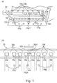
- Figure 3 illustrates a principal sectional view of an image forming apparatus to which the present invention is applicable.
- the process cartridge includes a photosensitive (member) drum and process means actable on the photosensitive drum.
- process means there are, e.g., a charging means for electrically charging a surface of the photosensitive drum, a developing device for forming an image on the photosensitive drum, and a cleaning means for removing a developer (containing toner, carrier, etc.) remaining on the photosensitive drum surface.
- a process cartridge A in this embodiment includes, as shown in Figure 2 , at a periphery of a photosensitive drum 11, a charging roller 12 as the charging means and a cleaner unit 24 including a cleaning blade 14, having elasticity, as the cleaning means. Further, the process cartridge A includes a developing device 38 including a first frame 17 and a second frame 18. The process cartridge A is constituted by integrally assembling the cleaner unit 24 and the developing device 38, and is constituted so as to be detachably mountable to an image forming apparatus main assembly B as shown in Figure 3 .
- the developing device 38 as a developing means includes a developing roller 13, a developing blade 15, a developer supplying roller 23, and a developer accommodating container 26 including a developer accommodating member 34 which is a flexible container for accommodating the developer and including a sealing member 19.
- a developer accommodating container is referred to as the developer accommodating container 26.
- the developing roller 13 and the developing blade 15 are supported by the first frame 17.
- the process cartridge A is mounted in the image forming apparatus main assembly B as shown in Figure 3 and is used for image formation.
- a sheet S is fed by a feeding roller 7 from a sheet cassette 6 mounted at a lower portion of the image forming apparatus and in synchronism with this sheet feeding, the photosensitive drum 11 is selectively exposed to light by an exposure device 8 to form a latent image.
- the developer is supplied to the developing roller 13 (developer carrying member) by the developer supplying roller 23 having a sponge shape and is carried in a thin layer on the surface of the developing roller 13 by the developing blade 15.
- the developing bias By applying a developing bias to the developing roller 13, the developer is supplied depending on the latent image and thus the latent image is developed into a developer image.
- This (developer) image is transferred onto the fed sheet S by bias voltage application to a transfer roller 9.
- the sheet S is conveyed to a fixing device 10, in which the image is fixed on the sheet S and then the sheet S is discharged by a sheet discharging region 1 to a sheet discharge portion 3 at an upper portion of the image forming apparatus.
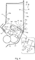
- Figure 4 is a sectional view of the developer accommodating unit 25 before unsealing
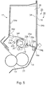
- Figure 5 is a cut-away perspective view of the developer accommodating container 26.
- the developer accommodating unit 25 is constituted, as shown in Figure 4 , by the developer accommodating container 26, the developing roller 13, the developing blade 15, and the first frame 17 and the second frame 18 which support these members.
- a combination of the first frame 17 and the second frame 18 constitute a frame for accommodating the developer accommodating container 26.
- the developer accommodating unit 25 is the same as the developing device 38. This is because the developer accommodating unit 25 includes the developing roller 13 and the developing blade 15. However, by supporting the developing roller 13 and the developing blade 15 by a frame which is separate from the developer accommodating unit 25, the developing roller 13 and the developing blade 15 may also be separated from the developer accommodating unit 25.
- the developing device 38 is constituted by the developer accommodating unit 25, the developing roller 13 and the developing blade 15 (not shown).
- the developer accommodating container 26 includes the developer accommodating member 34 and the sealing member 19 and the unsealing member 20.
- the developer accommodating member 34 is a flexible container in which a powdery developer is accommodatable.
- the developer accommodating member 34 is constituted by a molded portion 34a formed by subjecting a sheet-like material to vacuum molding, compressed-air molding or press molding, and a sheet-like air-permeable portion 34b having an air permeability.
- a bonding method between the molded portion 34a and the air-permeable portion 34b there are (thermal) welding, laser welding, an adhesive (bonding), an adhesive tape (bonding), and the like.
- the developer accommodating member 34 includes a discharging portion 35 which is openings for permitting discharge of the developer.
- the sealing member 19 is bonded to the developer accommodating member 34 so as to cover the discharging portion 35.
- the sealing member 19 is a sheet-like member having flexibility, and is peeled (pulled) off from the developer accommodating member 34 to expose the discharging portion 35, so that the developer can be made dischargeable from the developer accommodating container 26.
- the sealing member 19 is connected with an unsealing member 20 at a portion-to-be-engaged 19b, and the unsealing member 20 is rotatably supported by the second frame 18.
- a driving force is transmitted, and thus the unsealing member 20 is rotated in an arrow C direction, so that it is possible to wind up the sealing member 19 to expose the discharging portion 35.
- the developer accommodating container 26 is fixed by the portions-to-be-fixed 34g in an inside space formed by the first frame 17 and the second frame 18.
- the discharging portion 35 may preferably be configured so that the accommodated developer is easily discharged in its attitude during image formation. For that reason, in the attitude during the image formation, the discharging portion 35 is disposed so as to be directed downward with respect to the vertical direction.
- Figure 8 is a detailed illustration at a periphery of the discharging portion 35 provided to the developer accommodating member 34.
- a state in which the sealing member 19 is bonded onto the developer accommodating member 34 is shown.
- the sealing member 19 seals openings 35a and exposes the openings 35a by movement.
- a movement direction (in which the sealing member 19 is pulled by the unsealing member 20) of the sealing member 19 is a direction D.
- the exposure of the openings 35a in an unsealing direction E advances.
- the discharging portion 35 is constituted by a plurality of the openings 35a for permitting discharge of the inside developer, and a connection portions 35b which defines the plurality of openings 35a.
- the openings 35a and the connection portion 35b are disposed in a direction F perpendicular to the unsealing direction E.
- each of the plurality of openings 35a in Embodiment 1 has a round shape.
- the discharging portion 35 is, by the sealing member 19, continuously surrounded by a bonding portion 22 of the sealing member 19 is unsealably connected at a periphery of the discharging portion 35 to seal the developer accommodated in the developer accommodating member 34.
- the connecting portion 22 enables the sealing of the discharging portion 35 by being shaped in a rectangular shape which continuously surrounds two lines with respect to a long direction (direction F) and two lines with respect to a short direction (direction E).
- a first bonding portion 22a an early unsealed line is referred to was a first bonding portion 22a and a late unsealed line is referred to as a second bonding portion 22b.
- the bonding portion 22 which opposes the first bonding portion 22a via the openings 35a is the second boding portion 22b.
- the bonding portion 22 with respect to the short direction is referred to as a widthwise (short-side) bonding portion 22c.
- the unsealing direction is the direction E.
- the unsealing direction is defined as follows. In the case where the unsealing is performed by moving the sealing member 19, of the first bonding portion 22a and the second bonding portion 22b between which the openings 35a are interposed, the first bonding portion 22a is early unsealed (peeled).
- the developer accommodating member 34 is fixed inside the second frame 18 by the fixing portions 34g.
- the plurality of the fixing portions 34g are provided in parallel to the direction F in which the plurality of openings 35a are disposed, and receive a force when the sealing member 19 is unsealed from the developer accommodating member 34.
- the develops 34g may also be a single fixing portion, other than the plurality of the fixing portions 34g, which is long in parallel to the direction F.
- the fixing portions 34g of the developer accommodating member 34 are fixed on a fixing portion 18a of the second frame 18.
- a fixing means other than ultrasonic caulking, it is also possible to use means other than those using ultrasonic wave.
- the fixing means may also be thermal caulking using heat, thermal welding or ultrasonic welding which effect direct welding between the developer accommodating member 34 and the second frame 18, bonding using a solvent or an adhesive, clamping between the frames, thermal caulking, ultrasonic caulking, screw, hooking using a hole and a projected portion (boss or the like), etc.
- a region where the developer accommodating member 34 and the second frame 18 are bonded is the fixing portion.
- the thermal caulking, the ultrasonic caulking, the screw, the boss and the like a region where the clamping is made, a region where the thermal caulking (the ultrasonic caulking) is effected, a region where there is the screw, the boss or the like are the fixing portion.
- the frame 18a of the second frame 18 and the unsealing member 20 may preferably be provided so as to sandwich the discharging portion 35.
- the sealing member 19 is pulled, with respect to the fixing portion 18a of the second frame 18, in the direction of the arrow D by the unsealing member 20 during unsealing.
- the fixing portions 34g of the developer accommodating member 34 are fixed by the fixing portion 18a of the second frame 18.
- the sealing member 19 is pulled, in the directions of an arrow H and the arrow D, between the fixing portion 18a of the second frame 18 and the unsealing member 20.
- a force is applied to the first boding portion 22a of the developer accommodating member 34, so that the sealing member 19 is peeled in the arrow E direction.
- the discharging portion 35 may preferably be provided so as to be sandwiched in a range of a region M by the unsealing member 20 and the fixing portion 18a of the second frame 18.
- Figure 1 includes discharging portion illustrations at a periphery of the discharging portion 35 when peeling of the portion which is the first boding portion 22a to be first unsealed is ended and the openings 35a are exposed, and show a state in which the peeling of the second boding portion 22b of the developer accommodating member 34 is not ended.
- Figure 5 is a sectional view of the developer accommodating unit 25 in a state in which the peeling of the second boding portion 22b of the developer accommodating member 34 is not ended after the first boding portion 22a is peeled.
- Figure 6 is a sectional view of the developer accommodating unit 25 after the second boding portion 22b is peeled.
- the discharging portion 35 includes the plurality of the openings 35a with respect to the perpendicular direction F to the unsealing direction E in which the exposure of the openings 35a advances. For that reason, also the plurality of the connecting portions 35b are disposed at a plurality of positions with respect to the F direction.
- a relationship between the connecting portions 35b and the above-described fixing portions 34g of the developer accommodating member 34 is as follows. As shown in Figure 1 , of the connecting portions 35b located in the neighborhood of the discharging portion 35 with respect to the F direction, one connecting portion 35b1 and a fixing portion 34g1 of the developer accommodating member 34 are disposed so as to overlap with each other at least partly in a range of a region L of the connecting portion 35b1 with respect to the unsealing direction E. That is, in the unsealing direction E, the fixing portion 34g1 and the connecting portion 35b1 are disposed so as to overlap with each other.
- one fixing portion 34g1 When viewed from the unsealing direction E, at least a part of one fixing portion 34g1 is located in the range of the region L of one connecting portion 35d1, so that the connecting portion 35b1 performs a function of connecting the fixing portion 34g1 of the developer accommodating member 34 with the second boding portion 22b of the developer accommodating member 34. For that reason, it becomes possible that an unsealing force of the second boding portion 22b of the developer accommodating member 34 via the connecting portion 35b is received by the fixing portion 34g1 of the developer accommodating member 34. As a result, the connecting portion 35b1 can transmit a force, for peeling the sealing member 19 from the developer accommodating member 34, to the fixing portion 34g1 of the developer accommodating member 34. Therefore, the sealing member 19 is peelable also at the second boding portion 22b.
- Figure 9 includes detailed illustrations at a periphery of the discharging portion immediately before the second boding portion 22b is peeled.
- the force when the second boding portion 22b is unsealed is received by the fixing portions 34g of the developer accommodating member 34 via the connecting portions 35b, but a portion actually receiving the force is a range of a width Q1 where the force is exerted on the fixing portion 34g of the developer accommodating member 34.
- the openings 35a and the connecting portions 35b at the periphery of the openings 35a are not a little deformed.
- the central portion 34g1c of the fixing portion 34g1 which is the central portion of the range of the width Q1 in which the fixing portion 34g1 receives the force is disposed so as to be located at the central portion of the region L of the connecting portion 35b1.
- the force for unsealing the second boding portion 22b of the developer accommodating member 34 can be received by the fixing portion 34g1 of the developer accommodating member 34 via the connecting portion 35b, so that the sealing member 19 can be peeled.
- Such a constitution is effective in the case where the width Q1 of the fixing portion 34g of the developer accommodating member 34 is narrow particularly with respect to the region L of the connecting portion 35b1.
- Figure 10 includes detailed illustrations at the periphery of the discharging portion immediately before the second boding portion 22b is peeled.
- fixing portions 34g2 and 34g3 of the developer accommodating member 34 are disposed in a region between the opening 35a and the widthwise (short) boding portion 22c at both ends of the discharging portion 35a with respect to the F direction.
- the fixing portion 34g2 of the developer accommodating member 34 is disposed, and similarly in the range of L3, the fixing portion 34g3 of the developer accommodating member 34 is disposed.
- the fixing portions 34g2 and 34g3 of the developer accommodating member 34 and the second boding portion 22b of the developer accommodating member 34 are connected via the developer accommodating member 34.
- a flexure amount of the unsealing member 20 is, in the F direction shown in (a) of Figure 10 , smallest in the neighborhood of the both ends close to the portions where the unsealing member 20 is supported, and is largest in the neighborhood of the center remote from the portions where the unsealing member 20 is supported. Further, with a larger degree of the flexure of the unsealing member 20, timing of the unsealing of the sealing member 19 by the unsealing member 20 becomes later. By the flexure of the unsealing member 20, a distance between the unsealing member 20 and the first boding portion 22a becomes near.
- the sealing member 19 between the unsealing member 20 and the first boding portion 22a sags to have allowance, and this is because at the outset of start of winding-up by the unsealing member, only the sagging portion of the sealing member 19 is wound up. Therefore, with respect to the peeling of the second boding portion 22b of the developer accommodating member 34, the portions in the neighborhood of the both ends of the unsealing member 20 where the sagging is small are early wound up to act as a trigger for the peeling, and the portion in the neighborhood of the central portion of the unsealing member 20 where the sagging is large is finally peeled.
- the developer accommodating member 34 when the developer accommodating member 34 is largely deformed, the developer accommodating member 34 winds around the unsealing member 20, so that there is a fear that the unsealing does not start in the first place. Further, in a first stage in which the peeling starts, the force for the unsealing becomes large, and therefore when a shearing peeling state described later is formed by the deformation of the developer accommodating member 34, a larger force is needed.
- the fixing portions 34g2 and 34g3 of the developer accommodating member 34 are provided, with respect to the unsealing direction E, in the ranges of the regions L2 and L3 between the opening 35a and the widthwise boding portion 22c at the both ends of the discharging portion 35 with respect to the F direction. Further, when the peeling advances and the unsealing advances to the neighborhood of the central portion with respect to the F direction, the deformation of the developer accommodating member 34 becomes large. This is because all the portions bonded in regions other than the central portion are peeled, and therefore a peeling force for the developer accommodating member 34 concentrates at the center portion. When the developer accommodating member 34 is largely deformed, a problem such as wind-up around the unsealing member 20 similarly occurs.
- the fixing portion 34g1 is disposed, with respect to the unsealing direction E, in the range of region L of the connecting portion 35b1 with respect to the direction F in the neighborhood of the central portion of the discharging portion 35 with respect to the direction F.
- the sealing member 19 can be peeled with reliability.
- the connecting portion 35b1 and the fixing portion 34g1 are disposed so as to overlap with each other.
- the sealing member 19 can be peeled more reliably.
- FIG. 14 is an illustration, at the periphery of the discharging portion 35, showing a bonding pattern of the boding portions 22where the openings 35a are unsealed with the sealing member 19.
- FIG. 14 is an illustration, at the periphery of the discharging portion 35, showing an arrangement constitution of the openings 35a. Also in addition to the above-described constitution in which the periphery of the openings 35a is continuously surrounded by the boding portion 22 in the rectangular shape, the following constitutions may also be employed.
- the present invention is applied also in a constitution in which the sealing member 19 and the developer accommodating member 34 are connected by connecting portions 22 each surrounding an opening 35a as shown in (a) of Figure 14 , and in a constitution in which openings 35a are not completely arranged in a direction perpendicular to the unsealing direction E in a region of the connecting portion 22.
- the fixing portions 34g of the developer accommodating member 34 are located in the range of the region L of the connecting portions 35d, so that the force for unsealing the boding portion(s) 22 of the developer accommodating member 34 can be received by the fixing portions 34g of the developer accommodating member 34 via the connecting portions 35.
- the connecting portions 35b can transmit the force, for peeling the sealing member 19 from the developer accommodating member 34, to the fixing portions 34g of the developer accommodating member 34.
- the sealing member 19 is peelable also at the boding portion 22.
- the connecting portions 25 are present, so that the fixing portion 34g of the developer accommodating member 34 can be disposed in the range of the region L of the connecting portion 35b with respect to the unsealing direction E in which the exposure of the opening 35a advances.
- connecting portions 35b may also be constituted by a separate member.
- Figure 13 includes illustrations in which the discharging portion 35 is constituted by connecting members 16f, as the connecting portions, which are the separate member. Part (a) of Figure 13 is the illustration at the periphery of the discharging portion 35 constituted by the connecting members 16f, as the connecting portions 35b, which are the separate member, and (b) of Figure 13 is an enlarged with thereof.
- a single opening 35a long with respect to the direction F perpendicular to the unsealing direction E is provided, and at the long single opening 35a, along the unsealing direction E, the connecting members 16f which are the separate member for connecting the fixing portions 34g of the developer accommodating member 34 with the second boding portion 22b of the developer accommodating member 34 are provided.
- the connecting members 16f are bonded, by bonding, welding or the like, in each of the first boding portion 22a side and the second boding portion 22b side of the long single opening 35a.
- Figure 11 and Figure 12 Part (a) of Figure 11 and (b) of Figure 11 are illustrations in the case where the connecting portions 35b are not provided. Further, (c) of Figure 11 and (d) of Figure 11 are illustrations in the case where the fixing portions 34g of the developer accommodating member 34 are not disposed in ranges of regions of the connecting portions 35b with respect to the unsealing direction E in which the exposure of the openings 35a advances.
- the opening 35a in the neighborhood of the longitudinal central portion of the second boding portion 22b of the developer accommodating member 34 further largely opens, so that the sealing member 19 is wound around the unsealing member 20.
- Part (a) of Figure 16 is an illustration of A1-A2 cross section of (d) of Figure 10 .
- Part (a) of Figure 16 is a sectional view of a portion, which is a constitution of the direction, where the fixing portion and the connecting portion overlap with each other in the unsealing direction.
- Part (b) of Figure 16 is B1-B2 cross section of (d) of Figure 10 .
- Part (b) of Figure 16 is a sectional view of a portion, which is not the constitution of the present invention, where the fixing portion and the connecting portion do not overlap with each other with respect to the unsealing direction.
- the frame 18 is illustrated.
- the fixing portions 34g of the developer accommodating container 34 are disposed in the range of the region of the connecting portions 35b, so that the force for peeling the sealing member 19 and the boding portion 22 of the developer accommodating member 34 can be received by the fixing portions 34g of the developer accommodating member 34 via the connecting portions 35b. Therefore, the unsealing of the sealing member 19 of the developer accommodating member 34 can be stably effected with reliability.
Landscapes
- Physics & Mathematics (AREA)
- General Physics & Mathematics (AREA)
- Dry Development In Electrophotography (AREA)
- Closures For Containers (AREA)
Applications Claiming Priority (3)
| Application Number | Priority Date | Filing Date | Title |
|---|---|---|---|
| JP2011155834 | 2011-07-14 | ||
| JP2012123490A JP5959936B2 (ja) | 2011-07-14 | 2012-05-30 | 現像剤収納ユニット、プロセスカートリッジ、電子写真画像形成装置 |
| PCT/JP2012/068527 WO2013008952A1 (ja) | 2011-07-14 | 2012-07-13 | 現像剤収納ユニット、プロセスカートリッジ、電子写真画像形成装置 |
Publications (3)
| Publication Number | Publication Date |
|---|---|
| EP2733546A1 EP2733546A1 (en) | 2014-05-21 |
| EP2733546A4 EP2733546A4 (en) | 2014-12-24 |
| EP2733546B1 true EP2733546B1 (en) | 2018-09-12 |
Family
ID=47506223
Family Applications (1)
| Application Number | Title | Priority Date | Filing Date |
|---|---|---|---|
| EP12811743.9A Not-in-force EP2733546B1 (en) | 2011-07-14 | 2012-07-13 | Developer storage unit, process cartridge, and electrophotographic image forming device |
Country Status (6)
Families Citing this family (9)
| Publication number | Priority date | Publication date | Assignee | Title |
|---|---|---|---|---|
| PH12014500118A1 (en) * | 2011-07-14 | 2014-02-17 | Canon Kk | Developer accommodating unit, process cartridge, electrophotographic image forming apparatus |
| JP6116162B2 (ja) * | 2012-09-10 | 2017-04-19 | キヤノン株式会社 | 現像剤収容ユニット、現像装置、プロセスカートリッジ及び画像形成装置 |
| JP2015028594A (ja) * | 2013-06-24 | 2015-02-12 | キヤノン株式会社 | カートリッジ、プロセスカートリッジ及び画像形成装置 |
| JP6525662B2 (ja) * | 2015-03-27 | 2019-06-05 | キヤノン株式会社 | 現像剤容器、現像装置、プロセスカートリッジ、及び画像形成装置 |
| JP6604757B2 (ja) | 2015-06-30 | 2019-11-13 | キヤノン株式会社 | シール部材、ユニット及び画像形成装置 |
| JP6753112B2 (ja) * | 2016-03-31 | 2020-09-09 | ブラザー工業株式会社 | 現像剤カートリッジおよび現像剤収容ユニット |
| JP6766490B2 (ja) | 2016-07-14 | 2020-10-14 | ブラザー工業株式会社 | トナーカートリッジ |
| US10162288B2 (en) | 2016-09-23 | 2018-12-25 | Clover Technologies Group, Llc | System and method of remanufacturing a toner container |
| US9946199B1 (en) | 2016-09-23 | 2018-04-17 | Clover Technologies Group, Llc | System and method of filling a toner container |
Family Cites Families (13)
| Publication number | Priority date | Publication date | Assignee | Title |
|---|---|---|---|---|
| JPH0466980A (ja) | 1990-07-04 | 1992-03-03 | Canon Inc | 現像剤供給装置 |
| JPH05173419A (ja) * | 1991-02-25 | 1993-07-13 | Canon Inc | 現像剤供給装置及びプロセスカートリッジ |
| JPH05241447A (ja) * | 1992-03-03 | 1993-09-21 | Ricoh Co Ltd | 現像装置 |
| EP0736818A1 (en) | 1995-04-03 | 1996-10-09 | Canon Kabushiki Kaisha | Toner supply method, toner accommodation container, process cartridge and electrophotographic image forming apparatus |
| JPH096105A (ja) * | 1995-06-15 | 1997-01-10 | Canon Inc | プロセスカートリッジおよび現像装置およびトナーカートリッジおよび画像形成装置 |
| JPH09106156A (ja) * | 1995-10-09 | 1997-04-22 | Canon Inc | 現像剤容器、袋状シート及び現像剤充填装置 |
| US5594535A (en) * | 1995-11-07 | 1997-01-14 | Hewlett-Packard Company | Refillable toner cartridge |
| JPH10143050A (ja) * | 1996-09-12 | 1998-05-29 | Canon Inc | プロセスカートリッジ、現像剤容器、残余現像剤容器、プロセスカートリッジの組立方法、プロセスカートリッジの現像剤再充填方法、プロセスカートリッジに用いられる支持枠体及び支持枠体の組立て方法 |
| JP2002169366A (ja) * | 2000-12-05 | 2002-06-14 | Canon Inc | プロセスカートリッジ |
| US6763215B1 (en) * | 2001-06-27 | 2004-07-13 | Nu-Kote International, Inc. | Toner cartridge or cassette open/closure apparatus |
| JP2003228234A (ja) | 2002-02-01 | 2003-08-15 | Canon Inc | プロセスカートリッジ及び画像形成装置 |
| JP2003263014A (ja) * | 2002-03-07 | 2003-09-19 | Sharp Corp | トナー補給容器 |
| JP2011242757A (ja) | 2010-04-20 | 2011-12-01 | Canon Inc | 規制部材、クリーニング部材、現像装置、クリーニング装置、プロセスカートリッジ、及び画像形成装置 |
-
2012
- 2012-05-30 JP JP2012123490A patent/JP5959936B2/ja not_active Expired - Fee Related
- 2012-07-13 WO PCT/JP2012/068527 patent/WO2013008952A1/ja active Application Filing
- 2012-07-13 EP EP12811743.9A patent/EP2733546B1/en not_active Not-in-force
- 2012-07-13 PH PH1/2014/500114A patent/PH12014500114A1/en unknown
- 2012-07-13 CN CN201280034065.7A patent/CN103649844B/zh not_active Expired - Fee Related
-
2013
- 2013-07-26 US US13/951,663 patent/US8824918B2/en not_active Expired - Fee Related
Non-Patent Citations (1)
| Title |
|---|
| None * |
Also Published As
| Publication number | Publication date |
|---|---|
| EP2733546A4 (en) | 2014-12-24 |
| EP2733546A1 (en) | 2014-05-21 |
| WO2013008952A1 (ja) | 2013-01-17 |
| JP5959936B2 (ja) | 2016-08-02 |
| CN103649844A (zh) | 2014-03-19 |
| US8824918B2 (en) | 2014-09-02 |
| PH12014500114A1 (en) | 2022-11-23 |
| JP2013037341A (ja) | 2013-02-21 |
| CN103649844B (zh) | 2017-03-08 |
| US20130308973A1 (en) | 2013-11-21 |
Similar Documents
| Publication | Publication Date | Title |
|---|---|---|
| EP2733546B1 (en) | Developer storage unit, process cartridge, and electrophotographic image forming device | |
| US10620567B2 (en) | Developer accommodating unit, process cartridge and electrophotographic image forming apparatus | |
| EP2600206B1 (en) | Developer accommodating unit, process cartridge and electrophotographic image forming apparatus | |
| US9291942B2 (en) | Developer accommodating unit, process cartridge and image forming apparatus | |
| US9341983B2 (en) | Developer accommodating unit, developing device, process cartridge and image forming apparatus | |
| US9285707B2 (en) | Developer accommodating unit with a urging member for urging a flexible member | |
| US9052640B2 (en) | Developer accommodating unit, developing device, process cartridge and electrophotographic image forming apparatus | |
| EP2733547B1 (en) | Developer housing unit, process cartridge, and electrophotographic image forming device | |
| US9360831B2 (en) | Developing unit, process cartridge and image forming apparatus | |
| EP2733543B1 (en) | Developer storage container, process cartridge, and electrophotographic image forming device | |
| EP2733548B1 (en) | Developer storage unit, process cartridge, and electrophotographic image formation device | |
| US5974288A (en) | Electrophotographic image forming apparatus | |
| US9354553B2 (en) | Developer accommodating container, process cartridge and electrophotographic image forming apparatus | |
| US9213263B2 (en) | Flexible developer accommodating container with unsealable openings | |
| US9405225B2 (en) | Developer accommodating unit, process cartridge and image forming apparatus | |
| US20140072330A1 (en) | Developer accommodating unit, process cartridge and electrophotographic image forming apparatus |
Legal Events
| Date | Code | Title | Description |
|---|---|---|---|
| PUAI | Public reference made under article 153(3) epc to a published international application that has entered the european phase |
Free format text: ORIGINAL CODE: 0009012 |
|
| 17P | Request for examination filed |
Effective date: 20140214 |
|
| AK | Designated contracting states |
Kind code of ref document: A1 Designated state(s): AL AT BE BG CH CY CZ DE DK EE ES FI FR GB GR HR HU IE IS IT LI LT LU LV MC MK MT NL NO PL PT RO RS SE SI SK SM TR |
|
| DAX | Request for extension of the european patent (deleted) | ||
| A4 | Supplementary search report drawn up and despatched |
Effective date: 20141121 |
|
| RIC1 | Information provided on ipc code assigned before grant |
Ipc: G03G 15/08 20060101AFI20141117BHEP |
|
| GRAP | Despatch of communication of intention to grant a patent |
Free format text: ORIGINAL CODE: EPIDOSNIGR1 |
|
| STAA | Information on the status of an ep patent application or granted ep patent |
Free format text: STATUS: GRANT OF PATENT IS INTENDED |
|
| INTG | Intention to grant announced |
Effective date: 20180302 |
|
| GRAS | Grant fee paid |
Free format text: ORIGINAL CODE: EPIDOSNIGR3 |
|
| GRAA | (expected) grant |
Free format text: ORIGINAL CODE: 0009210 |
|
| STAA | Information on the status of an ep patent application or granted ep patent |
Free format text: STATUS: THE PATENT HAS BEEN GRANTED |
|
| AK | Designated contracting states |
Kind code of ref document: B1 Designated state(s): AL AT BE BG CH CY CZ DE DK EE ES FI FR GB GR HR HU IE IS IT LI LT LU LV MC MK MT NL NO PL PT RO RS SE SI SK SM TR |
|
| REG | Reference to a national code |
Ref country code: GB Ref legal event code: FG4D |
|
| REG | Reference to a national code |
Ref country code: CH Ref legal event code: EP |
|
| REG | Reference to a national code |
Ref country code: IE Ref legal event code: FG4D |
|
| REG | Reference to a national code |
Ref country code: DE Ref legal event code: R096 Ref document number: 602012051070 Country of ref document: DE |
|
| REG | Reference to a national code |
Ref country code: AT Ref legal event code: REF Ref document number: 1041324 Country of ref document: AT Kind code of ref document: T Effective date: 20181015 |
|
| REG | Reference to a national code |
Ref country code: NL Ref legal event code: MP Effective date: 20180912 |
|
| REG | Reference to a national code |
Ref country code: LT Ref legal event code: MG4D |
|
| PG25 | Lapsed in a contracting state [announced via postgrant information from national office to epo] |
Ref country code: FI Free format text: LAPSE BECAUSE OF FAILURE TO SUBMIT A TRANSLATION OF THE DESCRIPTION OR TO PAY THE FEE WITHIN THE PRESCRIBED TIME-LIMIT Effective date: 20180912 Ref country code: LT Free format text: LAPSE BECAUSE OF FAILURE TO SUBMIT A TRANSLATION OF THE DESCRIPTION OR TO PAY THE FEE WITHIN THE PRESCRIBED TIME-LIMIT Effective date: 20180912 Ref country code: RS Free format text: LAPSE BECAUSE OF FAILURE TO SUBMIT A TRANSLATION OF THE DESCRIPTION OR TO PAY THE FEE WITHIN THE PRESCRIBED TIME-LIMIT Effective date: 20180912 Ref country code: BG Free format text: LAPSE BECAUSE OF FAILURE TO SUBMIT A TRANSLATION OF THE DESCRIPTION OR TO PAY THE FEE WITHIN THE PRESCRIBED TIME-LIMIT Effective date: 20181212 Ref country code: NO Free format text: LAPSE BECAUSE OF FAILURE TO SUBMIT A TRANSLATION OF THE DESCRIPTION OR TO PAY THE FEE WITHIN THE PRESCRIBED TIME-LIMIT Effective date: 20181212 Ref country code: GR Free format text: LAPSE BECAUSE OF FAILURE TO SUBMIT A TRANSLATION OF THE DESCRIPTION OR TO PAY THE FEE WITHIN THE PRESCRIBED TIME-LIMIT Effective date: 20181213 Ref country code: SE Free format text: LAPSE BECAUSE OF FAILURE TO SUBMIT A TRANSLATION OF THE DESCRIPTION OR TO PAY THE FEE WITHIN THE PRESCRIBED TIME-LIMIT Effective date: 20180912 |
|
| PG25 | Lapsed in a contracting state [announced via postgrant information from national office to epo] |
Ref country code: AL Free format text: LAPSE BECAUSE OF FAILURE TO SUBMIT A TRANSLATION OF THE DESCRIPTION OR TO PAY THE FEE WITHIN THE PRESCRIBED TIME-LIMIT Effective date: 20180912 Ref country code: LV Free format text: LAPSE BECAUSE OF FAILURE TO SUBMIT A TRANSLATION OF THE DESCRIPTION OR TO PAY THE FEE WITHIN THE PRESCRIBED TIME-LIMIT Effective date: 20180912 Ref country code: HR Free format text: LAPSE BECAUSE OF FAILURE TO SUBMIT A TRANSLATION OF THE DESCRIPTION OR TO PAY THE FEE WITHIN THE PRESCRIBED TIME-LIMIT Effective date: 20180912 |
|
| REG | Reference to a national code |
Ref country code: AT Ref legal event code: MK05 Ref document number: 1041324 Country of ref document: AT Kind code of ref document: T Effective date: 20180912 |
|
| PG25 | Lapsed in a contracting state [announced via postgrant information from national office to epo] |
Ref country code: ES Free format text: LAPSE BECAUSE OF FAILURE TO SUBMIT A TRANSLATION OF THE DESCRIPTION OR TO PAY THE FEE WITHIN THE PRESCRIBED TIME-LIMIT Effective date: 20180912 Ref country code: IS Free format text: LAPSE BECAUSE OF FAILURE TO SUBMIT A TRANSLATION OF THE DESCRIPTION OR TO PAY THE FEE WITHIN THE PRESCRIBED TIME-LIMIT Effective date: 20190112 Ref country code: EE Free format text: LAPSE BECAUSE OF FAILURE TO SUBMIT A TRANSLATION OF THE DESCRIPTION OR TO PAY THE FEE WITHIN THE PRESCRIBED TIME-LIMIT Effective date: 20180912 Ref country code: PL Free format text: LAPSE BECAUSE OF FAILURE TO SUBMIT A TRANSLATION OF THE DESCRIPTION OR TO PAY THE FEE WITHIN THE PRESCRIBED TIME-LIMIT Effective date: 20180912 Ref country code: IT Free format text: LAPSE BECAUSE OF FAILURE TO SUBMIT A TRANSLATION OF THE DESCRIPTION OR TO PAY THE FEE WITHIN THE PRESCRIBED TIME-LIMIT Effective date: 20180912 Ref country code: RO Free format text: LAPSE BECAUSE OF FAILURE TO SUBMIT A TRANSLATION OF THE DESCRIPTION OR TO PAY THE FEE WITHIN THE PRESCRIBED TIME-LIMIT Effective date: 20180912 Ref country code: NL Free format text: LAPSE BECAUSE OF FAILURE TO SUBMIT A TRANSLATION OF THE DESCRIPTION OR TO PAY THE FEE WITHIN THE PRESCRIBED TIME-LIMIT Effective date: 20180912 Ref country code: AT Free format text: LAPSE BECAUSE OF FAILURE TO SUBMIT A TRANSLATION OF THE DESCRIPTION OR TO PAY THE FEE WITHIN THE PRESCRIBED TIME-LIMIT Effective date: 20180912 Ref country code: CZ Free format text: LAPSE BECAUSE OF FAILURE TO SUBMIT A TRANSLATION OF THE DESCRIPTION OR TO PAY THE FEE WITHIN THE PRESCRIBED TIME-LIMIT Effective date: 20180912 |
|
| PG25 | Lapsed in a contracting state [announced via postgrant information from national office to epo] |
Ref country code: SM Free format text: LAPSE BECAUSE OF FAILURE TO SUBMIT A TRANSLATION OF THE DESCRIPTION OR TO PAY THE FEE WITHIN THE PRESCRIBED TIME-LIMIT Effective date: 20180912 Ref country code: PT Free format text: LAPSE BECAUSE OF FAILURE TO SUBMIT A TRANSLATION OF THE DESCRIPTION OR TO PAY THE FEE WITHIN THE PRESCRIBED TIME-LIMIT Effective date: 20190112 Ref country code: SK Free format text: LAPSE BECAUSE OF FAILURE TO SUBMIT A TRANSLATION OF THE DESCRIPTION OR TO PAY THE FEE WITHIN THE PRESCRIBED TIME-LIMIT Effective date: 20180912 |
|
| REG | Reference to a national code |
Ref country code: DE Ref legal event code: R097 Ref document number: 602012051070 Country of ref document: DE |
|
| PLBE | No opposition filed within time limit |
Free format text: ORIGINAL CODE: 0009261 |
|
| STAA | Information on the status of an ep patent application or granted ep patent |
Free format text: STATUS: NO OPPOSITION FILED WITHIN TIME LIMIT |
|
| PG25 | Lapsed in a contracting state [announced via postgrant information from national office to epo] |
Ref country code: DK Free format text: LAPSE BECAUSE OF FAILURE TO SUBMIT A TRANSLATION OF THE DESCRIPTION OR TO PAY THE FEE WITHIN THE PRESCRIBED TIME-LIMIT Effective date: 20180912 |
|
| 26N | No opposition filed |
Effective date: 20190613 |
|
| PG25 | Lapsed in a contracting state [announced via postgrant information from national office to epo] |
Ref country code: SI Free format text: LAPSE BECAUSE OF FAILURE TO SUBMIT A TRANSLATION OF THE DESCRIPTION OR TO PAY THE FEE WITHIN THE PRESCRIBED TIME-LIMIT Effective date: 20180912 |
|
| PG25 | Lapsed in a contracting state [announced via postgrant information from national office to epo] |
Ref country code: MC Free format text: LAPSE BECAUSE OF FAILURE TO SUBMIT A TRANSLATION OF THE DESCRIPTION OR TO PAY THE FEE WITHIN THE PRESCRIBED TIME-LIMIT Effective date: 20180912 |
|
| REG | Reference to a national code |
Ref country code: CH Ref legal event code: PL |
|
| PG25 | Lapsed in a contracting state [announced via postgrant information from national office to epo] |
Ref country code: TR Free format text: LAPSE BECAUSE OF FAILURE TO SUBMIT A TRANSLATION OF THE DESCRIPTION OR TO PAY THE FEE WITHIN THE PRESCRIBED TIME-LIMIT Effective date: 20180912 |
|
| REG | Reference to a national code |
Ref country code: BE Ref legal event code: MM Effective date: 20190731 |
|
| PG25 | Lapsed in a contracting state [announced via postgrant information from national office to epo] |
Ref country code: CH Free format text: LAPSE BECAUSE OF NON-PAYMENT OF DUE FEES Effective date: 20190731 Ref country code: BE Free format text: LAPSE BECAUSE OF NON-PAYMENT OF DUE FEES Effective date: 20190731 Ref country code: LU Free format text: LAPSE BECAUSE OF NON-PAYMENT OF DUE FEES Effective date: 20190713 Ref country code: LI Free format text: LAPSE BECAUSE OF NON-PAYMENT OF DUE FEES Effective date: 20190731 |
|
| PG25 | Lapsed in a contracting state [announced via postgrant information from national office to epo] |
Ref country code: IE Free format text: LAPSE BECAUSE OF NON-PAYMENT OF DUE FEES Effective date: 20190713 |
|
| PGFP | Annual fee paid to national office [announced via postgrant information from national office to epo] |
Ref country code: FR Payment date: 20200728 Year of fee payment: 9 Ref country code: DE Payment date: 20200928 Year of fee payment: 9 Ref country code: GB Payment date: 20200724 Year of fee payment: 9 |
|
| PG25 | Lapsed in a contracting state [announced via postgrant information from national office to epo] |
Ref country code: CY Free format text: LAPSE BECAUSE OF FAILURE TO SUBMIT A TRANSLATION OF THE DESCRIPTION OR TO PAY THE FEE WITHIN THE PRESCRIBED TIME-LIMIT Effective date: 20180912 |
|
| PG25 | Lapsed in a contracting state [announced via postgrant information from national office to epo] |
Ref country code: HU Free format text: LAPSE BECAUSE OF FAILURE TO SUBMIT A TRANSLATION OF THE DESCRIPTION OR TO PAY THE FEE WITHIN THE PRESCRIBED TIME-LIMIT; INVALID AB INITIO Effective date: 20120713 Ref country code: MT Free format text: LAPSE BECAUSE OF FAILURE TO SUBMIT A TRANSLATION OF THE DESCRIPTION OR TO PAY THE FEE WITHIN THE PRESCRIBED TIME-LIMIT Effective date: 20180912 |
|
| REG | Reference to a national code |
Ref country code: DE Ref legal event code: R119 Ref document number: 602012051070 Country of ref document: DE |
|
| GBPC | Gb: european patent ceased through non-payment of renewal fee |
Effective date: 20210713 |
|
| PG25 | Lapsed in a contracting state [announced via postgrant information from national office to epo] |
Ref country code: GB Free format text: LAPSE BECAUSE OF NON-PAYMENT OF DUE FEES Effective date: 20210713 Ref country code: DE Free format text: LAPSE BECAUSE OF NON-PAYMENT OF DUE FEES Effective date: 20220201 |
|
| PG25 | Lapsed in a contracting state [announced via postgrant information from national office to epo] |
Ref country code: FR Free format text: LAPSE BECAUSE OF NON-PAYMENT OF DUE FEES Effective date: 20210731 |
|
| PG25 | Lapsed in a contracting state [announced via postgrant information from national office to epo] |
Ref country code: MK Free format text: LAPSE BECAUSE OF FAILURE TO SUBMIT A TRANSLATION OF THE DESCRIPTION OR TO PAY THE FEE WITHIN THE PRESCRIBED TIME-LIMIT Effective date: 20180912 |