WO2012176564A1 - 剛性中子 - Google Patents
剛性中子 Download PDFInfo
- Publication number
- WO2012176564A1 WO2012176564A1 PCT/JP2012/062802 JP2012062802W WO2012176564A1 WO 2012176564 A1 WO2012176564 A1 WO 2012176564A1 JP 2012062802 W JP2012062802 W JP 2012062802W WO 2012176564 A1 WO2012176564 A1 WO 2012176564A1
- Authority
- WO
- WIPO (PCT)
- Prior art keywords
- core
- axial direction
- rigid
- segment
- side plate
- Prior art date
- Legal status (The legal status is an assumption and is not a legal conclusion. Google has not performed a legal analysis and makes no representation as to the accuracy of the status listed.)
- Ceased
Links
Images




Classifications
-
- B—PERFORMING OPERATIONS; TRANSPORTING
- B29—WORKING OF PLASTICS; WORKING OF SUBSTANCES IN A PLASTIC STATE IN GENERAL
- B29C—SHAPING OR JOINING OF PLASTICS; SHAPING OF MATERIAL IN A PLASTIC STATE, NOT OTHERWISE PROVIDED FOR; AFTER-TREATMENT OF THE SHAPED PRODUCTS, e.g. REPAIRING
- B29C33/00—Moulds or cores; Details thereof or accessories therefor
- B29C33/76—Cores
-
- B—PERFORMING OPERATIONS; TRANSPORTING
- B29—WORKING OF PLASTICS; WORKING OF SUBSTANCES IN A PLASTIC STATE IN GENERAL
- B29D—PRODUCING PARTICULAR ARTICLES FROM PLASTICS OR FROM SUBSTANCES IN A PLASTIC STATE
- B29D30/00—Producing pneumatic or solid tyres or parts thereof
- B29D30/06—Pneumatic tyres or parts thereof (e.g. produced by casting, moulding, compression moulding, injection moulding, centrifugal casting)
- B29D30/0601—Vulcanising tyres; Vulcanising presses for tyres
- B29D30/0661—Rigid cores therefor, e.g. annular or substantially toroidal cores
Definitions
- the present invention relates to a rigid core capable of accurately and efficiently performing removal of a rigid core from a pneumatic tire and reassembly of the removed rigid core.
- the rigid core a includes an annular core body a1 that forms a lumen surface of the pneumatic tire from a plurality of core segments c that are divided in the tire circumferential direction. It is formed.
- the core segment c includes a first core segment c1 in which the dividing surfaces at both ends in the circumferential direction are inclined in a direction in which the circumferential width decreases toward the inside in the radial direction, and the dividing surfaces at both ends in the circumferential direction are in the radial direction. It is comprised from the 2nd core segment c2 which inclines in the direction which the circumferential direction width
- These core segments c1 and c2 are alternately arranged in the circumferential direction.
- Such core segments c are sequentially moved from the second core segment c2 in the radial direction one by one and taken out. Thereby, the core main body a1 is disassembled and removed from the vulcanized tire.
- the inner end portions of the core segments c1 and c2 in the radial direction are bolted to the annular core portion d1 of the frame d.
- the core main body a1 is assembled in an annular shape.
- the frame d is open at one end of the core part d1. Thereby, the attachment / detachment operation of the bolt e can be performed from the opening f.
- an object of the present invention is to provide a rigid core that can be assembled and disassembled with high accuracy, stability and efficiency without using bolts, and can greatly contribute to the automation of assembly and disassembly.
- the invention of claim 1 of the present application is a rigid core comprising an annular core body provided on the outer surface with a molding surface for molding a lumen surface of a pneumatic tire,
- the core body composed of a plurality of core segments divided in the tire circumferential direction and movable inward in the radial direction, and inserted into the center hole of the core body to move the core segments inward in the radial direction It is arranged on both sides of the core body in the axial direction of the core body and prevents the movement of each core segment in the axial direction by holding the core body between the inner side surfaces.
- a first dovetail portion comprising one of an ant groove or an ant tenon extending in the axial direction is formed on the outer peripheral surface of the core, and an inner peripheral surface of each core segment.
- a dovetail groove extending in the axial direction and engaging with the first dovetail joint or
- a second dovetail portion comprising the other of the tenons is formed, the side plate on one side in the axial direction is fixed to the end on one side of the core, and the side plate on the other side in the axial direction is the side plate
- a boss portion that can be screwed into an inner screw portion provided in a central hole of the core is provided on the inner side surface of the core so as to be detachable from the other end portion of the core.
- the core segment includes a first core segment in which split surfaces at both ends in the circumferential direction are inclined in a direction in which the circumferential width decreases toward the inside in the radial direction
- the first core segment is composed of second core segments that are alternately arranged in the circumferential direction and in which the dividing surfaces at both ends in the circumferential direction are inclined inward in the radial direction so as to increase the circumferential width.
- the invention according to claim 3 is characterized in that the side plates on one side and the other side in the axial direction each include a support shaft portion protruding outward in the axial direction.
- the invention of claim 4 is characterized in that the support shaft portion is formed with a locking portion formed of a key groove or a key-like projection for preventing rotation on an end surface thereof.
- the present invention includes a cylindrical core inserted in the core body and a pair of side plates disposed on both sides in the axial direction of the core body. One end of the core is fixed to one side plate.
- a first dovetail portion extending in the axial direction is formed on the outer peripheral surface of the core.
- a second dovetail portion extending in the axial direction is formed on the inner peripheral surface of each core segment. Therefore, in the present invention, the core segments can be sequentially arranged around the core while being guided by the first dovetail portion. At this time, since the first and second dovetail joints are engaged with each other, misalignment of the core segment can be prevented, and high-precision, stable and efficient assembly can be achieved.
- a boss portion that can be screwed into the center hole of the core is protruded from the other side plate.
- the pair of side plates can hold the core body and prevent the movement of the core segments in the axial direction. Accordingly, in the present invention, the engagement between the first and second dovetail joints, the movement of the core segment in the radial direction by the core, and the axial direction of the core segment due to the clamping between the side plates are performed. It is possible to fix the assembled core segments by preventing the movement of the cores. Thereby, the rigid core can maintain the core body with high accuracy.
- the present invention can greatly contribute to automation of assembly and disassembly of the rigid core.
- FIG. 1 It is sectional drawing which shows one Example of the rigid core of this invention. It is a top view which shows a core main body with a core. It is a disassembled perspective view of a rigid core. It is an enlarged view which shows the engagement state of the 1st, 2nd dovetail part. It is sectional drawing explaining a connection means.
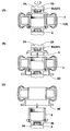
- (A)-(C) are sectional views for explaining the order of disassembling the rigid core. It is sectional drawing explaining taking out from the tire of a core main body, and an assembly. It is a top view explaining taking out from a tire of a core main part, and assembling. It is sectional drawing explaining the attachment to the core of the other side plate.
- (A) is sectional drawing which shows the formation method of the pneumatic tire which used the rigid core
- (B) is a side view of the axial direction of a rigid core.
- the rigid core 1 of the present embodiment includes an annular core body 3 provided with a molding surface 2 that molds the lumen surface Ts of the pneumatic tire T, and the core body 3.
- a cylindrical core 5 inserted in the center hole 3H and a pair of side plates 6L and 6U disposed on both sides in the axial direction of the core body 3 are provided.
- FIG. 1 shows a state in which the rigid core 1 is taken out from the vulcanization mold together with the vulcanized pneumatic tire T and transferred onto the holding shaft 4.
- the core body 3 includes a bulging portion 3B that bulges outward in the axial direction on the radially inner side of the main portion 3A having the molding surface 2.
- the bulging portion 3B has a tapered surface 7 that is inclined outward in the axial direction toward the inner side in the radial direction.
- a concave portion 8 concentric with the core body 3 is formed in the core body 3.
- the recess 8 of this example a case where steam, which is a heat medium for vulcanization heating, is supplied through a flow path (not shown) provided in the core 5 is shown, but the present invention is limited to this. Do not mean.
- the recess 8 can accommodate a heat source for vulcanization heating such as an electric heater.
- the recessed part 8 is used also as a hook part hooked on the holding jig 41 (shown in FIG. 7) described later. Thereby, the holding jig 41 can suspend the disassembled core body 3 and take out the tire T from the core body 3.
- the core body 3 includes a plurality of core segments 9 divided in the tire circumferential direction as shown in FIGS.
- the core segment 9 includes a first core segment 9A in which the dividing surfaces 9S at both ends in the circumferential direction are inclined in a direction in which the circumferential width decreases toward the inside in the radial direction, and the dividing surfaces 9S at both ends in the circumferential direction.
- the second core segment 9B is inclined in the direction in which the circumferential width increases inward in the radial direction.
- the core segment 9 can sequentially move the second core segment 9B and the first core segment 9A radially inward. Accordingly, as shown in FIGS. 7 and 8, the core body 3 can be sequentially removed from the inner cavity TH of the tire T by moving one by one radially inward from the second core segment 9B. .
- the core 5 has a cylindrical shape and is inserted into the center hole 3H of the core body 3. As a result, the core 5 can prevent the core segments 9 from moving inward in the radial direction. Further, one end of the core 5 in the axial direction is fixed to the inner surface of the side plate 6L on the one axial side.
- the core 5 and the side plate 6L on one side are fixed using a bolt 10 (shown in FIG. 1) is shown.
- the core 5 and the side plate 6 ⁇ / b> L on one side are integrally removed from the core body 3.
- the bolt fixing does not affect the disassembling and assembling work of the rigid core 1 at all. Therefore, the core 5 and the side plate 6L on one side can be fixed by, for example, welding.
- the core 5 has an inner screw portion 13 formed on the other side in the axial direction of the center hole 5H. Further, a first dovetail portion 16 formed of one of the dovetail groove 14 or the dovetail tenon 15 extending continuously in the axial direction is formed on the outer peripheral surface of the core 5. On the other hand, on the inner peripheral surface of each core segment 9, a second dovetail portion 17 comprising the other of the dovetail groove 14 or the dovetail tenon 15 extending in the axial direction and engaging with the first dovetail portion 16. Is formed.
- the dovetail groove 14 is formed as the first dovetail joint 16 and the ant tenon 15 is formed as the second dovetail joint 17 is shown, but the present invention is not limited to this.
- the ant tenon 15 may be formed as the first ant joint 16 and the ant groove 14 may be formed as the second ant joint 17.
- the dovetail groove 14 and the ant tenon 15 have a substantially trapezoidal cross section in which both side surfaces are inclined in the direction of increasing the width toward the groove bottom and tenon tip, as is well known. .
- the core 5 and the core segment 9 are connected to each other so as to be relatively movable only in the axial direction by the dovetail groove 14 and the dovetail tenon 15 being fitted to each other.
- the one side plate 6L includes a side plate body 11 including a disc-shaped substrate portion 11A and a flange portion 11B provided on the outer circumferential edge thereof.
- a support shaft portion 12 that protrudes outward in the axial direction is provided concentrically on the outer surface of the substrate portion 11A.
- the flange portion 11 ⁇ / b> B has the same inclination as the tapered surface 7 of the core body 3 and abuts against the tapered surface 7. Thereby, the flange part 11B can position the side plate 6L on one side and the core body 3 concentrically. Further, the flange portion 11B can sandwich and hold the bulging portion 3B of the core body 3 between the flange portion 11B and the core 5.
- the side plate 6U on the other side in the axial direction includes a side plate body 20 including a disc-shaped substrate portion 20A and a flange portion 20B provided on the outer circumferential edge thereof.
- a support shaft portion 21 that protrudes outward in the axial direction is provided concentrically on the outer surface of the substrate portion 20A. Further, the flange portion 20 ⁇ / b> B contacts the tapered surface 7 of the core body 3. Thus, in this example, the substrate portion 20A and the support shaft portion 21 are formed in the same configuration as the substrate portion 11A and the support shaft portion 12 of the one side plate 6L.
- a boss portion 22 that can be screwed into an inner screw portion 13 provided in the center hole 5H of the core 5 is provided concentrically on the inner side surface of the substrate portion 20A.
- the boss portion 22 is screwed into the inner screw portion 13.
- the other side plate 6U is detachably attached to the core 5.
- the flange portion 20B can align the side plate 6U and the core body 3 concentrically as in the case of the one side plate 6L. Further, the flange portion 20B can sandwich and hold the bulging portion 3B of the core body 3 between the flange portion 20B and the core 5.
- a rotating shaft 23 driven by a motor is connected to a support shaft portion 21 of the other side plate 6U via a connecting means 24.
- the rotating shaft 23 is used for attaching and detaching the other side plate 6U.
- the holding shaft 4 is connected to the support shaft portion 12 of the one side plate 6 ⁇ / b> L via a connecting means 24.
- the holding shaft 4 and the rotating shaft 23 may be collectively referred to as a connecting shaft 25.
- the connecting means 24 has a ball lock mechanism in this example. As shown in FIG. 5, the connecting means 24 protrudes concentrically from the connecting hole portion 26 concentrically provided at the outer end portions of the support shaft portions 12 and 21 and the outer end portion of the connecting shaft 25. And a connecting cylinder portion 27. The connecting cylinder part 27 is inserted into the connecting hole part 26. Further, the connecting means 24 includes ball locking means 28 for locking between the connecting hole portion 26 and the connecting cylinder portion 27.
- the connecting hole portion 26 is provided with a circumferential groove 26A on the inner peripheral surface thereof. Further, the connecting cylinder portion 27 is provided with a plurality of through holes 29 that are distributed in the circumferential direction and penetrate inward and outward in the radial direction.
- the ball lock means 28 includes a rigid ball 30 held in the through hole 29 of the connecting cylinder portion 27, a piston piece 33 housed in the cylinder chamber 31 in the connecting shaft 25, and a center hole 27H of the connecting cylinder portion 27. And a plunger 34 disposed therein.
- the piston piece 33 moves in and out of the axial direction in the cylinder chamber 31 by supplying and discharging compressed air to and from the cylinder chamber 31.
- the plunger 34 is connected to the piston piece 33 so as to be movable together. As a result, the plunger 34 can move outward in the axial direction within the central hole 27H of the connecting cylinder portion 27 as the piston piece 33 moves outward in the axial direction.
- the outer peripheral surface of the plunger 34 has a cone surface that is tapered outward in the axial direction.
- Such a plunger 34 is capable of pushing up each of the rigid balls 30 outward in the radial direction by moving the outer peripheral surface thereof in contact with each of the rigid balls 30 by moving outward in the axial direction. Thereby, each rigid ball 30 is pressed into the circumferential groove 26 ⁇ / b> A and can lock between the connecting hole portion 26 and the connecting cylindrical portion 27.
- the plunger 34 can move inward in the axial direction within the center hole 27H of the connecting cylinder portion 27 by moving the piston piece 33 inward in the axial direction. Accordingly, the plunger 34 can release the rigid ball 30 from being pushed outward in the radial direction, and can release the lock between the connection hole portion 26 and the connection cylinder portion 27.
- a locking portion 36 (shown in FIG. 3) formed of one of a key groove for rotation prevention or a key-like protrusion is formed on the outer end surfaces of the support shaft portions 12 and 21.
- an engaging portion (not shown) made of the other of the keyway or the key-like protrusion is formed on the outer end surface of the connecting shaft 25. The engaging portion engages with the locking portion 36. Thereby, the latching
- FIG. 1 shows a state where the rigid core 1 with the pneumatic tire taken out from the vulcanization mold is transferred onto the holding shaft 4 as described above.
- the rotary shaft 23 is lowered to the support shaft portion 21 side of the other side plate 6U. Then, the rotating shaft 23 and the support shaft portion 21 are connected by one touch using the connecting means 24.
- the other side plate 6U can be removed from the core 5 from the rigid core 1, as shown in FIG.
- the removed side plate 6U on one side is transferred to another place together with the rotary shaft 23 while being held by the connecting means 24.
- the core body 3 is supported by an annular core body receiver 40 rising from below.
- the holding shaft 4 is lowered together with the other side plate 6U.
- the side plate 6U and the core 5 on the other side are integrally removed from the rigid core 1.
- the removed side plate 6U and the core 5 on the other side are transferred to the assembly place K (shown in FIG. 7) together with the holding shaft 4 while being held by the connecting means 24.
- the core segments 9 are taken out one by one from the core body 3 held on the core body receiver 40 by, for example, a holding jig 41 attached to the robot arm.
- the removed core segment 9 is transferred to the assembly location K and is sequentially attached around the core 5.
- the holding jig 41 of the present example has a hook shape that can hook the concave portion 8 of the core body 3. Such a holding jig 41 can move each core segment 9 radially inward, then hang down the core segment 9 and transfer it to the assembly location K.
- the core segments 9 are taken out one by one from the second core segment 9B as shown in FIG. 8 as described above. Then, after all the second core segments 9B are taken out, the first core segments 9A are taken out one by one.
- each core segment 9 is connected to the first core 5.
- the dovetail portions 16 are sequentially arranged around the core 5 while being guided.
- positional displacement of the core segment 9 can be prevented and high-precision and stable assembly can be achieved.
- a boss portion 22 that can be screwed to the core 5 is provided on the other side plate 6U.
- the core body 3 is held between the pair of side plates 6L and 6U by the screwing of the boss portion 22, and the core segments 9 can be prevented from moving in the axial direction.
- the assembled core segments 9 and 9 can be fixed by preventing the core segment 9 from moving in the axial direction by holding. Thereby, the rigid core 1 can maintain the core body 3 with high accuracy.
- the rigid core 1 is fixed by only one screw connection without using a bolt, the assembly work efficiency and the disassembly work efficiency can be greatly increased. Therefore, it is possible to greatly contribute to the automation of assembly and disassembly of the rigid core 1.
Landscapes
- Engineering & Computer Science (AREA)
- Mechanical Engineering (AREA)
- Moulds For Moulding Plastics Or The Like (AREA)
- Heating, Cooling, Or Curing Plastics Or The Like In General (AREA)
- Tyre Moulding (AREA)
Abstract
Description
2 成形面
3 中子本体
3H 中心孔
5 コア
5H 中心孔
6L、6U 側板
9 中子セグメント
9A 第1の中子セグメント
9B 第2の中子セグメント
9S 分割面
12 支持軸部
13 内ネジ部
14 蟻溝
15 蟻ほぞ
16 第1の蟻継ぎ部
17 第2の蟻継ぎ部
21 支持軸部
22 ボス部
36 係止部
T 空気入りタイヤ
Ts 内腔面
図1に示すように、本実施形態の剛性中子1は、空気入りタイヤTの内腔面Tsを成形する成形面2を設けた円環状の中子本体3と、この中子本体3の中心孔3Hに内挿される円筒状のコア5と、前記中子本体3の軸心方向両側に配される一対の側板6L、6Uとを具える。
図1には、前述した如く、加硫金型から取り出された空気入りタイヤ付きの剛性中子1が、保持軸4上に移載された状態が示される。図6(A)に示すように、先ず、回転軸23を、他方の側板6Uの支持軸部21側に下降させる。そして、この回転軸23と支持軸部21とを、連結手段24を用いてワンタッチで連結させる。
Claims (4)
- 空気入りタイヤの内腔面を成形する成形面を外表面に設けた円環状の中子本体を具える剛性中子であって、
タイヤ周方向に分割されかつ半径方向内側に移動可能な複数の中子セグメントからなる前記中子本体と、
この中子本体の中心孔に内挿されて各中子セグメントの半径方向内側への移動を阻止する円筒状のコアと、
前記中子本体の軸心方向両側に配され、内側面間で前記中子本体を挟んで保持することにより各中子セグメントの軸心方向への移動を阻止する一対の側板とを具え、
しかも前記コアの外周面に、軸心方向にのびる蟻溝又は蟻ほぞの一方からなる第1の蟻継ぎ部が形成され、かつ各中子セグメントの内周面に、軸心方向にのびかつ前記第1の蟻継ぎ部に係合する蟻溝又は蟻ほぞの他方からなる第2の蟻継ぎ部が形成されるとともに、
軸心方向一方側の側板は、前記コアの一方側の端部が固定され、かつ軸心方向他方側の側板は、この側板の内側面に、前記コアの中心孔に設ける内ネジ部に螺入しうるボス部を突設することにより、前記コアの他方側の端部とは着脱自在としたことを特徴とする剛性中子。 - 前記中子セグメントは、周方向両端の分割面を、半径方向内方に向かって周方向巾が減じる向きに傾斜させた第1の中子セグメントと、前記第1の中子セグメントとは周方向に交互に配され、かつ周方向両端の分割面を、半径方向内方に向かって周方向巾が増す向きに傾斜させた第2の中子セグメントとから構成されることにより、半径方向内側に移動可能としたことを特徴とする請求項1記載の剛性中子。
- 前記軸心方向一方側、他方側の側板は、それぞれ軸心方向外側に突出する支持軸部を具えることを特徴とする請求項1又は2記載の剛性中子。
- 前記支持軸部は、その端面に、廻り止め用のキー溝又はキー状突起からなる係止部が形成されることを特徴とする請求項3記載の剛性中子。
Priority Applications (2)
| Application Number | Priority Date | Filing Date | Title |
|---|---|---|---|
| CN201280030987.0A CN103619570B (zh) | 2011-06-23 | 2012-05-18 | 刚性芯 |
| BR112013033099-6A BR112013033099B1 (pt) | 2011-06-23 | 2012-05-18 | núcleo rígido |
Applications Claiming Priority (2)
| Application Number | Priority Date | Filing Date | Title |
|---|---|---|---|
| JP2011-139747 | 2011-06-23 | ||
| JP2011139747A JP5662882B2 (ja) | 2011-06-23 | 2011-06-23 | 剛性中子 |
Publications (1)
| Publication Number | Publication Date |
|---|---|
| WO2012176564A1 true WO2012176564A1 (ja) | 2012-12-27 |
Family
ID=47422408
Family Applications (1)
| Application Number | Title | Priority Date | Filing Date |
|---|---|---|---|
| PCT/JP2012/062802 Ceased WO2012176564A1 (ja) | 2011-06-23 | 2012-05-18 | 剛性中子 |
Country Status (4)
| Country | Link |
|---|---|
| JP (1) | JP5662882B2 (ja) |
| CN (1) | CN103619570B (ja) |
| BR (1) | BR112013033099B1 (ja) |
| WO (1) | WO2012176564A1 (ja) |
Cited By (1)
| Publication number | Priority date | Publication date | Assignee | Title |
|---|---|---|---|---|
| CN105711057A (zh) * | 2016-03-24 | 2016-06-29 | 中山市悦辰科技实业有限公司 | 一种弧形管专用成型模具 |
Citations (4)
| Publication number | Priority date | Publication date | Assignee | Title |
|---|---|---|---|---|
| JPS56162631A (en) * | 1980-05-02 | 1981-12-14 | Sumitomo Rubber Ind Ltd | Tire molding drum |
| JPH0557760A (ja) * | 1991-09-03 | 1993-03-09 | Copal Co Ltd | アンダーカツト部を有する射出成形金型 |
| JP2007152957A (ja) * | 2005-12-02 | 2007-06-21 | Goodyear Tire & Rubber Co:The | タイヤ製造用コアのラッチ機構および移動機構 |
| JP2008213289A (ja) * | 2007-03-05 | 2008-09-18 | Bridgestone Corp | タイヤ製造用内型および該内型を用いたタイヤ製造方法 |
Family Cites Families (5)
| Publication number | Priority date | Publication date | Assignee | Title |
|---|---|---|---|---|
| JPS55103942A (en) * | 1979-02-01 | 1980-08-08 | Bridgestone Corp | Forming drum for tyre |
| JPS6439106U (ja) * | 1987-09-03 | 1989-03-08 | ||
| JP2671287B2 (ja) * | 1993-02-04 | 1997-10-29 | 泰太郎 藤井 | タイヤ |
| JP2603913Y2 (ja) * | 1993-08-23 | 2000-04-04 | 株式会社ブリヂストン | タイヤ成形ドラム |
| CN201275882Y (zh) * | 2008-09-29 | 2009-07-22 | 中橡集团曙光橡胶工业研究设计院 | 燕尾槽式鼓芯结构的成型机头 |
-
2011
- 2011-06-23 JP JP2011139747A patent/JP5662882B2/ja active Active
-
2012
- 2012-05-18 CN CN201280030987.0A patent/CN103619570B/zh not_active Expired - Fee Related
- 2012-05-18 WO PCT/JP2012/062802 patent/WO2012176564A1/ja not_active Ceased
- 2012-05-18 BR BR112013033099-6A patent/BR112013033099B1/pt not_active IP Right Cessation
Patent Citations (4)
| Publication number | Priority date | Publication date | Assignee | Title |
|---|---|---|---|---|
| JPS56162631A (en) * | 1980-05-02 | 1981-12-14 | Sumitomo Rubber Ind Ltd | Tire molding drum |
| JPH0557760A (ja) * | 1991-09-03 | 1993-03-09 | Copal Co Ltd | アンダーカツト部を有する射出成形金型 |
| JP2007152957A (ja) * | 2005-12-02 | 2007-06-21 | Goodyear Tire & Rubber Co:The | タイヤ製造用コアのラッチ機構および移動機構 |
| JP2008213289A (ja) * | 2007-03-05 | 2008-09-18 | Bridgestone Corp | タイヤ製造用内型および該内型を用いたタイヤ製造方法 |
Cited By (1)
| Publication number | Priority date | Publication date | Assignee | Title |
|---|---|---|---|---|
| CN105711057A (zh) * | 2016-03-24 | 2016-06-29 | 中山市悦辰科技实业有限公司 | 一种弧形管专用成型模具 |
Also Published As
| Publication number | Publication date |
|---|---|
| BR112013033099A2 (pt) | 2017-01-24 |
| CN103619570B (zh) | 2016-04-13 |
| JP2013006326A (ja) | 2013-01-10 |
| CN103619570A (zh) | 2014-03-05 |
| BR112013033099B1 (pt) | 2020-12-22 |
| JP5662882B2 (ja) | 2015-02-04 |
Similar Documents
| Publication | Publication Date | Title |
|---|---|---|
| JP5113861B2 (ja) | 空気入りタイヤの製造方法、及びそれに用いる剛性中子 | |
| JP5089150B2 (ja) | タイヤ製造用コアのラッチ機構および移動機構 | |
| US20150210025A1 (en) | System for molding non-pneumatic tires | |
| JP5432955B2 (ja) | 剛性中子 | |
| JP5107566B2 (ja) | タイヤ製造用コア | |
| JP5261541B2 (ja) | 剛性中子 | |
| JP2001088143A (ja) | タイヤ製造用の2つの部分からなる剛性コア | |
| JP5662882B2 (ja) | 剛性中子 | |
| JP5364124B2 (ja) | 剛性中子の保持構造 | |
| CN216466332U (zh) | 一种便于拆装的轮胎硫化设备 | |
| JP5492149B2 (ja) | 剛性中子、及びそれを用いたタイヤの製造方法 | |
| CN111660473B (zh) | 轮胎硫化模具 | |
| CN102869486B (zh) | 轮胎硫化装置 | |
| KR101926325B1 (ko) | 가류 블라더용 하부 클램프링 조립장치 | |
| JP5662883B2 (ja) | 剛性中子 | |
| JP6693265B2 (ja) | タイヤ形成用の剛性中子 | |
| CN216760500U (zh) | 一种轮胎的硫化模具 | |
| US20240262063A1 (en) | Mold for forming a tire and tire production method | |
| CN211843953U (zh) | 滑板车和滑板车的轮胎 | |
| CN110418708B (zh) | 具有可拆卸地附接的薄片的带有可互换件的轮胎模具 | |
| CN109016587B (zh) | 可伸缩装置及轮胎模具 | |
| JP2015171795A (ja) | タイヤ形成用の剛性中子 | |
| JP2019188709A (ja) | タイヤ加硫用ブラダ組立体の取付方法 | |
| MXPA98002996A (en) | Apparatus and process to change a side wall insert of a tire or neumat mold |
Legal Events
| Date | Code | Title | Description |
|---|---|---|---|
| 121 | Ep: the epo has been informed by wipo that ep was designated in this application |
Ref document number: 12803062 Country of ref document: EP Kind code of ref document: A1 |
|
| NENP | Non-entry into the national phase |
Ref country code: DE |
|
| REG | Reference to national code |
Ref country code: BR Ref legal event code: B01A Ref document number: 112013033099 Country of ref document: BR |
|
| 122 | Ep: pct application non-entry in european phase |
Ref document number: 12803062 Country of ref document: EP Kind code of ref document: A1 |
|
| ENP | Entry into the national phase |
Ref document number: 112013033099 Country of ref document: BR Kind code of ref document: A2 Effective date: 20131220 |