WO2012172940A1 - 熱処理方法、外側継手部材、及びトリポード型等速自在継手 - Google Patents
熱処理方法、外側継手部材、及びトリポード型等速自在継手 Download PDFInfo
- Publication number
- WO2012172940A1 WO2012172940A1 PCT/JP2012/063176 JP2012063176W WO2012172940A1 WO 2012172940 A1 WO2012172940 A1 WO 2012172940A1 JP 2012063176 W JP2012063176 W JP 2012063176W WO 2012172940 A1 WO2012172940 A1 WO 2012172940A1
- Authority
- WO
- WIPO (PCT)
- Prior art keywords
- inner diameter
- diameter portion
- large inner
- heat treatment
- joint member
- Prior art date
- Legal status (The legal status is an assumption and is not a legal conclusion. Google has not performed a legal analysis and makes no representation as to the accuracy of the status listed.)
- Ceased
Links
Images






Classifications
-
- C—CHEMISTRY; METALLURGY
- C21—METALLURGY OF IRON
- C21D—MODIFYING THE PHYSICAL STRUCTURE OF FERROUS METALS; GENERAL DEVICES FOR HEAT TREATMENT OF FERROUS OR NON-FERROUS METALS OR ALLOYS; MAKING METAL MALLEABLE, e.g. BY DECARBURISATION OR TEMPERING
- C21D1/00—General methods or devices for heat treatment, e.g. annealing, hardening, quenching or tempering
- C21D1/06—Surface hardening
- C21D1/09—Surface hardening by direct application of electrical or wave energy; by particle radiation
- C21D1/10—Surface hardening by direct application of electrical or wave energy; by particle radiation by electric induction
-
- C—CHEMISTRY; METALLURGY
- C21—METALLURGY OF IRON
- C21D—MODIFYING THE PHYSICAL STRUCTURE OF FERROUS METALS; GENERAL DEVICES FOR HEAT TREATMENT OF FERROUS OR NON-FERROUS METALS OR ALLOYS; MAKING METAL MALLEABLE, e.g. BY DECARBURISATION OR TEMPERING
- C21D1/00—General methods or devices for heat treatment, e.g. annealing, hardening, quenching or tempering
-
- C—CHEMISTRY; METALLURGY
- C21—METALLURGY OF IRON
- C21D—MODIFYING THE PHYSICAL STRUCTURE OF FERROUS METALS; GENERAL DEVICES FOR HEAT TREATMENT OF FERROUS OR NON-FERROUS METALS OR ALLOYS; MAKING METAL MALLEABLE, e.g. BY DECARBURISATION OR TEMPERING
- C21D9/00—Heat treatment, e.g. annealing, hardening, quenching or tempering, adapted for particular articles; Furnaces therefor
- C21D9/40—Heat treatment, e.g. annealing, hardening, quenching or tempering, adapted for particular articles; Furnaces therefor for rings; for bearing races
-
- F—MECHANICAL ENGINEERING; LIGHTING; HEATING; WEAPONS; BLASTING
- F16—ENGINEERING ELEMENTS AND UNITS; GENERAL MEASURES FOR PRODUCING AND MAINTAINING EFFECTIVE FUNCTIONING OF MACHINES OR INSTALLATIONS; THERMAL INSULATION IN GENERAL
- F16D—COUPLINGS FOR TRANSMITTING ROTATION; CLUTCHES; BRAKES
- F16D3/00—Yielding couplings, i.e. with means permitting movement between the connected parts during the drive
- F16D3/16—Universal joints in which flexibility is produced by means of pivots or sliding or rolling connecting parts
- F16D3/20—Universal joints in which flexibility is produced by means of pivots or sliding or rolling connecting parts one coupling part entering a sleeve of the other coupling part and connected thereto by sliding or rolling members
- F16D3/202—Universal joints in which flexibility is produced by means of pivots or sliding or rolling connecting parts one coupling part entering a sleeve of the other coupling part and connected thereto by sliding or rolling members one coupling part having radially projecting pins, e.g. tripod joints
- F16D3/205—Universal joints in which flexibility is produced by means of pivots or sliding or rolling connecting parts one coupling part entering a sleeve of the other coupling part and connected thereto by sliding or rolling members one coupling part having radially projecting pins, e.g. tripod joints the pins extending radially outwardly from the coupling part
- F16D3/2055—Universal joints in which flexibility is produced by means of pivots or sliding or rolling connecting parts one coupling part entering a sleeve of the other coupling part and connected thereto by sliding or rolling members one coupling part having radially projecting pins, e.g. tripod joints the pins extending radially outwardly from the coupling part having three pins, i.e. true tripod joints
-
- F—MECHANICAL ENGINEERING; LIGHTING; HEATING; WEAPONS; BLASTING
- F16—ENGINEERING ELEMENTS AND UNITS; GENERAL MEASURES FOR PRODUCING AND MAINTAINING EFFECTIVE FUNCTIONING OF MACHINES OR INSTALLATIONS; THERMAL INSULATION IN GENERAL
- F16D—COUPLINGS FOR TRANSMITTING ROTATION; CLUTCHES; BRAKES
- F16D2300/00—Special features for couplings or clutches
- F16D2300/10—Surface characteristics; Details related to material surfaces
-
- Y—GENERAL TAGGING OF NEW TECHNOLOGICAL DEVELOPMENTS; GENERAL TAGGING OF CROSS-SECTIONAL TECHNOLOGIES SPANNING OVER SEVERAL SECTIONS OF THE IPC; TECHNICAL SUBJECTS COVERED BY FORMER USPC CROSS-REFERENCE ART COLLECTIONS [XRACs] AND DIGESTS
- Y02—TECHNOLOGIES OR APPLICATIONS FOR MITIGATION OR ADAPTATION AGAINST CLIMATE CHANGE
- Y02P—CLIMATE CHANGE MITIGATION TECHNOLOGIES IN THE PRODUCTION OR PROCESSING OF GOODS
- Y02P10/00—Technologies related to metal processing
- Y02P10/25—Process efficiency
Definitions
- the present invention relates to a heat treatment method, an outer joint member, and a tripod type constant velocity universal joint.
- the tripod type constant velocity universal joint As a constant velocity universal joint used for power transmission devices such as automobiles and various industrial machines, there is a tripod type constant velocity universal joint using a tripod member as an inner joint member.
- the tripod type constant velocity universal joint includes an outer joint member 1, a tripod member 2 as an inner joint member, and a torque transmission member 3.
- the outer joint member 1 includes a cup-shaped mouth portion 4 opened at one end and a shaft portion 5 protruding from the bottom wall of the mouth portion 4.
- Three track grooves 6 extending in the axial direction are formed on the inner peripheral surface of the mouse portion 4.
- Roller guide surfaces (roller slidable contact surfaces) 7a and 7a are formed on the side walls of each track groove 6 facing each other in the circumferential direction.
- the tripod member 2 includes a boss 8 and a leg shaft 9.
- the boss 8 is formed with a spline or serration hole 11 coupled to a shaft (not shown) so as to be able to transmit torque.
- the leg shaft 9 protrudes in the radial direction from the circumferentially divided position of the boss 8.
- the torque transmission member 3 includes a roller 20 that is rotatably fitted to the outer periphery of the leg shaft 9 via a plurality of needle rollers 22.
- the cylindrical outer peripheral surface 14 of the leg shaft 9 provides the inner raceway surface of the needle roller 22.
- the inner peripheral surface of the roller 20 is cylindrical and provides the outer raceway surface of the needle roller 22.
- the needle roller 22 is in contact with the outer washer 24 at the outer end face viewed in the radial direction of the leg shaft 9, and is in contact with the inner washer 28 at the opposite end face. Since the outer washer 24 is restricted from moving in the axial direction by a circlip 26 mounted in the ring groove 16, the needle roller 22 is also restricted from moving in the axial direction.
- the inner diameter surface of the mouse portion 4 of the outer joint member 1 has a three-valve corollary shape in which small inner diameter portions 7b and large inner diameter portions 7c that appear alternately in the circumferential direction are connected by a roller guide surface 7a. That is, in the outer joint member 1, track grooves 6 composed of roller guide surfaces 7a, 7a facing each other in the circumferential direction and a large inner diameter portion 7c provided between both roller guide surfaces 7a, 7a are formed at three locations on the inner periphery. It is what is done.
- thermosetting treatment There is induction hardening as the thermosetting treatment, and induction hardening includes a one-shot (one-shot) hardening method (Patent Document 1) in which heat treatment is performed at a fixed position, and moving hardening in which the coil and the outer joint member move relatively. It is broadly divided into the input method (Patent Document 2).
- the one-shot quenching uses a high-frequency heating apparatus including a high-frequency induction heating coil 17 having heating portions 17a, 17a, and 17a that are respectively inserted into the three track grooves 6 of the outer joint member 1.
- a high-frequency heating apparatus including a high-frequency induction heating coil 17 having heating portions 17a, 17a, and 17a that are respectively inserted into the three track grooves 6 of the outer joint member 1.
- the roller guide surface 7a can be heated and cooled at once over the entire region in the joint axial direction.
- a non-conductive ferrite core is attached to the induction coil in order not to form a hardened layer on the inner surface of the large inner diameter portion 7c.
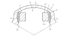
- the hardened layer S can be formed only on the surface of the roller guide surface 7a as shown in FIG.
- the moving quenching method uses a high-frequency heating apparatus shown in FIGS.
- the high-frequency heating apparatus includes a coil 18 wound in a three-leaf clover shape and a cooling jacket 19 attached to the coil 18.
- the coil 18 includes substantially triangular heating portions 18a, 18a, 18a arranged at a pitch of about 120 ° along the circumferential direction.
- the heating part 18a has curved parts 20a, 20a facing the roller guide surface 7a, a straight part 20c facing the small inner diameter part 7b, and a straight part 20b facing the large inner diameter part 7c.
- the shape of the cooling jacket 19 is a three-leaf clover shape similar to the coil 18.
- the coil 18 and the cooling jacket 19 are moved in the mouth portion 4 of the outer joint member 1 along the axial direction.
- the heating surface (roller guide surface 7a, small inner diameter 7b and large inner diameter portion 7c) is heated, and this heating surface is rapidly cooled with cooling water ejected from the cooling jacket 19 following this heating. become.
- the roller guide surface 7a, the small inner diameter 7b, and the large inner diameter portion 7c are heat-cured to form a hardened layer S.
- one-shot quenching method heating is performed at a time and cooling is performed at a time, so that distortion is likely to occur in thin-walled parts, etc. There is a demerit that depth difference is caused and non-uniformity.
- moving quenching has the effect of stabilizing the generated strain and making it uniform by controlling the depth of the hardened hardening layer.
- a boot band tightening groove 10 is formed on the outer periphery of the outer joint member 1, and the thickness of this portion is thin. For this reason, in this thin part, the hardened layer S may come off to the outer peripheral side, and this part may become weak in strength. For this reason, there existed a demerit that the freedom degree of design, such as it becoming difficult to miniaturize a joint, was restricted.
- the present invention is a heat treatment method that can form an outer joint member of a tripod type constant velocity universal joint that is excellent in strength without forming a hardened layer in a large inner diameter portion by induction hardening of induction hardening.
- the present invention intends to provide an outer joint member and a tripod type constant velocity universal joint configured by such a heat treatment method.
- the first heat treatment method of the present invention is an outer joint member in which a track groove comprising a roller guide surface facing in the circumferential direction and a large inner diameter portion provided between both roller guide surfaces is formed at three locations on the inner periphery.
- the first heat treatment method of the present invention it is possible to suppress the temperature rise of the large inner diameter portion by injecting cooling water to the large inner diameter portion. For this reason, at the time of the moving quenching by the high frequency induction heating coil, it is possible to prevent the temperature (a large inner diameter portion) from rising to the austenitizing temperature.
- the heat treatment apparatus of the present invention is a roller guide surface facing in the circumferential direction and an outer joint member in which track grooves comprising a large inner diameter portion provided between both roller guide surfaces are formed at three locations on the inner periphery.
- a cooling means for the large inner diameter portion that suppresses the temperature rise of the large inner diameter portion.
- the cooling water can be sprayed to the large inner diameter portion by the large inner diameter portion cooling means. For this reason, at the time of the moving quenching by the high frequency induction heating coil, it is possible to prevent the temperature (a large inner diameter portion) from rising to the austenitizing temperature.
- the large inner diameter portion cooling means includes a large inner diameter portion cooling jacket disposed in the vicinity of the large inner diameter portion, and the large inner diameter portion cooling jacket is sprayed to inject cooling water into the large inner diameter portion. It can consist of one with an open mouth. If a cooling jacket for the large inner diameter portion is disposed, the cooling water can be stably jetted from the jacket to the large inner diameter portion.
- a concave portion in which the cooling jacket for the large inner diameter portion is disposed is provided in a portion corresponding to the large inner diameter portion in the high frequency induction heating coil.
- the large inner diameter cooling jacket may be made of a non-magnetic material or may be made of an insulating material. If the cooling jacket for the large inner diameter portion is a non-magnetic material or an insulating material, the jacket itself is prevented from generating heat because it is not induction-heated even when receiving a magnetic line of force generated in the high-frequency induction heating coil.
- the cooling means for the large inner diameter portion preferably includes a flow rate adjusting means for controlling the injection amount of the cooling water to the large inner diameter portion. If the flow rate adjusting means is provided, the cooling condition can be changed. Moreover, the cooling means for the large inner diameter portion may be provided with a timing control means for controlling the timing of cooling water injection to the large inner diameter portion. In the case of including the timing control means, the cooling water can be injected at an arbitrary timing.
- the cooling means for the large inner diameter portion may form a range that cools the large inner diameter portion and a range that is not cooled. In such a case, the entire large inner diameter portion can be cooled, or a part of the large inner diameter portion can be prevented from being cooled.
- the cooling means for the large inner diameter portion may be capable of changing the injection position of the cooling water. In this way, the cooling range can be changed.
- the heat treatment apparatus can be used as a heat treatment method.
- the outer joint member of the tripod type constant velocity universal joint can be treated by the heat treatment method.
- the tripod type constant velocity universal joint of the present invention is mounted on the outer joint member, a tripod member having three leg shafts disposed in the outer joint member and projecting in the radial direction, and each leg shaft of the tripod member. And a roller member guided in the axial direction of the outer joint member along the roller guide surface.
- an unfired portion can be provided in the large inner diameter portion of the outer joint member, and a large inner diameter portion excellent in strength can be formed, and a stable hardened layer can be formed in other portions.
- the cooling jacket for the large inner diameter portion is arranged in the vicinity of the large inner diameter portion, the cooling water can be stably jetted from the jacket to the large inner diameter portion, and the unburned portion can be stably ejected to the large inner diameter portion. Can be formed. By providing the recess, the apparatus can be made compact.
- the cooling jacket for the large inner diameter portion is a magnetic body or an insulating material, it will not be induction heated even if it receives the magnetic lines of force generated in the high frequency induction heating coil, so that the unfired portion is stably formed in the large inner diameter portion. be able to.
- the cooling conditions can be changed, and an unfired portion can be formed corresponding to the product to be heat-treated.
- the cooling water can be injected at an arbitrary timing, and the workability can be improved.
- the cooling means for the inner diameter portion can form a range for cooling with respect to the large inner diameter portion and a range not to cool, the entire large inner diameter portion is not cooled or a part of the large inner diameter portion is not cooled.
- the unburned portion can be formed in the optimum range.
- the cooling means for the large inner diameter portion can form an unfired portion in an optimum range according to each product, as long as the cooling water injection position can be changed.
- the outer joint member of the tripod type constant velocity universal joint of the present invention is processed by the heat treatment method, it is stable in strength and excellent in durability.
- the tripod type constant velocity universal joint of the present invention uses the outer joint member treated by the heat treatment method, it becomes a high quality tripod type constant velocity universal joint excellent in durability, and further, downsizing of the joint, etc. The degree of design freedom increases.
- the tripod constant velocity universal joint can be applied to various types.
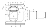
- FIG. 3 is a longitudinal sectional view of the tripod type constant velocity universal joint shown in FIG. 2.
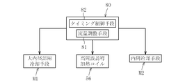
- FIG. 2 is a simplified block diagram which shows the structure of the heat processing apparatus of this invention.
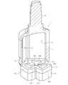
- FIG. drawing which shows the comparative example of a heat processing apparatus. It is a perspective view of the heat-heating process state by the one-shot hardening method. It is principal part sectional drawing of the heat-heating process state by the one-shot hardening method.
- FIG. 1 is a cross-sectional view of a main part of an outer joint member subjected to thermosetting treatment by the heat treatment method according to the present invention.
- This outer joint member is a tripod type constant velocity universal joint as shown in FIGS. Used.
- the tripod type constant velocity universal joint includes an outer joint member 31, a tripod member 32 as an inner joint member, and a torque transmission member 33.
- the outer joint member 31 has a cup-shaped mouth portion 34 opened at one end, and a stem portion 35 protruding from the bottom wall of the mouth portion 34, and is axially located at a three-way position in the circumferential direction of the inner circumference.
- An extending track groove 36 is formed.
- the mouse portion 34 has a non-cylindrical shape in which a large diameter portion 34a and a small diameter portion 34b appear alternately when viewed in cross section. That is, the mouse portion 34 is formed with the large-diameter portion 34a and the small-diameter portion 34b, so that the three track grooves 36 extending in the axial direction are formed on the inner peripheral surface thereof.
- Roller guide surfaces (roller sliding contact surfaces) 37, 37 are formed on the side walls of each track groove 36 facing in the circumferential direction.
- the inner diameter surface has a three-valve corollary shape in which small inner diameter portions 42 and large inner diameter portions 43 that appear alternately in the circumferential direction are connected by a roller guide surface 37. That is, in the outer joint member 31, the track groove 36 composed of the roller guide surface 37 facing the circumferential direction and the large inner diameter portion 43 provided between the roller guide surfaces 37, 37 is formed at three locations on the inner periphery. Is.
- the tripod member 32 includes a boss 38 and a leg shaft 39.
- the boss 38 is formed with a spline or serration hole 41 that is coupled to a shaft (not shown) so as to be able to transmit torque.
- the leg shaft 39 protrudes in the radial direction from the circumferentially divided position of the boss 38.
- Each leg shaft 39 includes a cylindrical outer peripheral surface 44 and an annular ring groove 46 formed near the shaft end.
- a roller member 50 constituting the torque transmission member 33 is externally fitted to the outer periphery of the leg shaft 39 via a plurality of needle rollers 47.
- the cylindrical outer peripheral surface 44 of the leg shaft 39 provides the inner raceway surface of the needle roller 47.
- the inner peripheral surface of the roller member 50 is cylindrical and provides the outer raceway surface of the needle roller 47.
- the needle roller 47 is in contact with the outer washer 51 at the outer end face seen in the radial direction of the leg shaft 39, and is in contact with the inner washer 52 at the opposite end face. Since the outer washer 51 is restricted from moving in the axial direction by the circlip 53 mounted in the ring groove 46, the needle roller 47 is also restricted from moving in the axial direction.
- the opening of the outer joint member 31 is sealed by a boot (not shown). Therefore, a boot mounting portion having a concave groove is formed on the opening side of the outer diameter surface of the outer joint member 31. Then, the boot is fitted on the boot mounting portion, and tightened with a boot band, whereby the boot is mounted on the boot mounting portion of the outer joint member 31.
- a hardened layer S (see FIGS. 1 and 2) is formed on the inner diameter surface of the mouth portion 34 of the outer joint member 31.
- an unbaked portion 55 is formed in the large inner diameter portion 43.
- the unbaked portion 55 is not the entire large-diameter portion 43 but the hardened layer S is formed at the end in the circumferential direction.
- the unbaked part 55 is formed using the cooling means M1 for large inner diameter parts (see FIG. 4) described later.
- the high frequency induction heating coil 56 includes three fitting portions 56A, 56B, and 56C that are fitted into the track groove 36, and linear portions 57A, 57B, and 57C that face the small inner diameter portion.
- the straight portion 57C includes a branch portion 58 provided continuously with the first fitting portion 56A and a branch portion 59 provided continuously with the third fitting portion 56B.
- each of the fitting portions 56A, 56B, 56C includes a curved portion 60, 60 facing the roller guide surface 37 and a linear portion 61 facing the large inner diameter portion 43.
- the straight portion 61 is provided with a recess 62 on the surface facing the large inner diameter portion.
- a large inner diameter cooling jacket 65 of the large inner diameter cooling means M1 is disposed in the recess 62.
- the large inner diameter cooling jacket 65 is formed of a flat rectangular hollow body, and has a convex curved surface 66 so that the opposing surface of the large inner diameter facing wall faces the large inner diameter portion 43.
- An insulating plate 67 is disposed in the recess 62, and the large inner diameter cooling jacket 65 is fitted into the recess 62 through the insulating plate 67.
- a plurality of cooling water injection ports 68 are provided on the inner diameter facing wall. That is, the large inner diameter portion 43 is sprayed to the large inner diameter portion 43 through the cooling water injection port 68 of the cooling jacket 65.
- the large inner diameter cooling jacket 65 can be made of a nonmagnetic material such as brass or copper, or can be made of an insulating material of resin such as epoxy.
- the control unit of the heat treatment apparatus includes control means 80 that controls energization to the high frequency induction heating coil 56.
- the control means 80 controls the large inner diameter cooling means M1. That is, the large inner diameter cooling jacket 65 has pipes connected to the jet ports 68, and valve means that opens and closes by a control signal from the control means 80 is provided in the pipes.
- the cooling water can be jetted from the jet outlet 68 at an arbitrary timing by the control of the timing control means 82 of the control means 80.
- the flow rate adjusting means 81 may be formed by configuring the valve means with an electric valve or the like capable of adjusting the flow rate.
- the control means 80 is constituted by a microcomputer or the like, for example.
- the high-frequency heating apparatus is provided with an inner peripheral cooling means M2 for cooling the heat-treated part.
- the inner periphery cooling means M ⁇ b> 2 includes an inner periphery cooling jacket disposed below the high frequency induction heating coil 56. That is, the inner periphery cooling jacket injects cooling water to the inner periphery of the outer joint member 31 to perform cooling in the quenching process.
- a high frequency induction heating coil 56 having a large inner diameter cooling jacket 65 and an inner peripheral cooling jacket (not shown) is inserted into the outer joint member 31, and a high frequency current is passed through the high frequency induction heating coil 56, whereby the outer joint member 31. Heat the inner circumference of the. That is, a high frequency current is passed through the high frequency induction heating coil 56 from a high frequency power supply (not shown). At this time, the high-frequency current flows in the order of the fitting portion 56A ⁇ the fitting portion 56B ⁇ the fitting portion 56C. However, the direction of flow due to the alternating current is alternated. In this way, an induced electromotive force is generated by the electromagnetic induction action when the high-frequency current flows. Due to this electromagnetic induction action, Joule heat is generated, and the roller guide surface 37 and the like of the outer joint member 31 can be heated.
- a large inner diameter portion cooling jacket 65 is arranged in each of the fitting portions 56A, 56B, 56C of the high frequency induction heating coil 56, and the high frequency induction heating coil 56 is supplied with a high frequency current. Cooling water is injected into the large inner diameter portion 43 from the outlet 68 of the large inner diameter cooling jacket 65 simultaneously with the start of heating of the roller guide surface 37 and the like by energization or at a timing slightly earlier than this heating. That is, energization of the high-frequency current is controlled by the energization control unit of the control unit 80, and the timing of cooling water injection is controlled by the timing unit 82 of the control unit 80.
- the temperature rise in the large inner diameter portion 43 is suppressed by the injection of the cooling water.
- the roller guide surface 37 and the small inner diameter portion 42 are heated without being affected by the cooling water of the large inner diameter portion cooling jacket 65, so that the austenitizing temperature is increased.
- the high frequency induction heating coil 56 is sequentially moved from the opening side of the mouse part to the back side of the mouse part.
- the roller guide surface 37 and the small inner diameter portion 42 are heated from the opening side to the back side. That is, the roller guide surface 37 and the like are sequentially heated in accordance with the relative movement of the high-frequency induction heating coil 56, and the heating portion is rapidly cooled with the cooling fluid, so that induction hardening is performed.
- the large inner diameter portion 43 is not heated, and it is possible to prevent the temperature (a large inner diameter portion) from rising to the austenitizing temperature. Accordingly, the unfired portion 55 can be provided in the large inner diameter portion 43 of the outer joint member 31, and the large inner diameter portion 43 excellent in strength can be formed, and the stable hardened layer S can be formed in other portions.
- the cooling jacket 65 for the large inner diameter portion is disposed in the vicinity of the large inner diameter portion 43, the cooling water can be stably injected from the jacket 65 to the large inner diameter portion 43, and the large inner diameter portion 43 can be stably injected. An unbaked portion 55 can be formed. Further, since the cooling jacket 65 for the large inner diameter portion is fitted into the concave portion 62 provided in the large inner diameter portion corresponding portion of the coil 56, the apparatus can be made compact.
- the cooling jacket 65 for the large inner diameter portion is a magnetic material or an insulating material, it will not be induction heated even if it receives the magnetic lines of force generated in the high-frequency induction heating coil 56, so 55 can be formed.
- the cooling condition can be changed, and an unfired portion can be formed corresponding to the product to be heat-treated.
- the cooling water can be injected at an arbitrary timing, and the workability can be improved.
- the large inner diameter cooling means M1 can form an unfired portion in an optimum range according to each product as long as the cooling water injection position can be changed.
- the outer joint member 31 in which the hardened layer S is thus formed is processed by the heat treatment method, it is stable in strength and excellent in durability. Further, the outer joint member 31 formed in this way can assemble a tripod type constant velocity universal joint as shown in FIGS. For this reason, this tripod type constant velocity universal joint uses the outer joint member processed by the heat treatment method, so that it becomes a high quality tripod type constant velocity universal joint with excellent durability, and further downsizing the joint. The degree of freedom in design is increased.
- the ferromagnetic core 90 is formed as a recess without using cooling water. It may be fitted.
- the ferromagnetic core 90 blocks the magnetic field lines generated in the high frequency induction heating coil 56. That is, the ferromagnetic core 90 is attached to the coil with a material having high magnetic permeability and has the effect of concentrating the magnetic lines of force on the workpiece to enhance the power, while being used to block the magnetic lines and prevent unintended heating.
- the unfired portion 55 can be added to the large inner diameter portion 43 which is impossible with the conventional transfer firing. Can be provided.
- the generated magnetic lines of force may be weakened by the ferromagnetic core 90 even in the range H on the large inner diameter side of the track surface (roller guide surface) 37. There is. Thus, if it becomes weak, there exists a possibility that the hardening layer formed in this range H may become shallow, as shown in FIG. For this reason, when the ferromagnetic core 90 is used, it is necessary to set the shape, arrangement, and the like of the ferromagnetic core 90 in consideration of this.
- the unfired portion 55 is formed along the axial direction in the circumferential central portion of the large inner diameter portion 43, but the entire large inner diameter portion 43 may be the unbaked portion 55.
- the unbaked portion 55 may not be provided on the joint inner side of the large inner diameter portion 43. That is, in the large inner diameter portion 43, the hardened layer S may be provided on the opening (inlet portion) side corresponding to the boot mounting portion and the joint back side excluding the portion at the position for regular use. This is because even if the hardened layer is provided on the joint inner side of the large inner diameter portion 43, the influence on the strength is small.
- the hardened layer S may or may not be provided for the small inner diameter portion 42, and the hardened layer S may be provided only on the roller guide surface 37. For this reason, the hardened layer S can be formed in an optimum range without impairing the function as the outer joint member 31.
- the cooling water supply path of the cooling jacket 65 for the large inner diameter portion The cooling water supply path of the circumferential cooling jacket may be a separate system or the same system.
- the number, the diameter, the arrangement position, and the like of the injection ports 68 of the large inner diameter cooling jacket 65 can be variously changed. For this reason, if the cooling jacket 65 for the large inner diameter portion is replaceable, a plurality of types of jackets 65 having different numbers, diameters, arrangement positions, and the like of the injection ports 68 can be prepared.
- the roller is a so-called single roller type that includes a roller that is rotatably fitted to the cylindrical outer peripheral surface of the leg shaft 39 via a plurality of needle rollers 47.
- Other types such as a so-called double roller type equipped with
- a quenching method capable of forming an optimal hardened layer in consideration of the structure of the outer joint member of the tripod type constant velocity universal joint and taking advantage of the moving quenching.
- This heat treatment method makes it possible to manufacture an outer joint member of a tripod type constant velocity universal joint that is stable in strength.
Landscapes
- Chemical & Material Sciences (AREA)
- Engineering & Computer Science (AREA)
- Mechanical Engineering (AREA)
- Physics & Mathematics (AREA)
- Thermal Sciences (AREA)
- Crystallography & Structural Chemistry (AREA)
- Materials Engineering (AREA)
- Metallurgy (AREA)
- Organic Chemistry (AREA)
- General Engineering & Computer Science (AREA)
- Heat Treatment Of Articles (AREA)
Abstract
高周波焼入れの移動焼入れでもって、大内径部に硬化層を形成することなく強度的に優れたトリポード型等速自在継手の外側継手部材を成形できる熱処理方法、このような熱処理方法で構成された外側継手部材及びトリポード型等速自在継手を提供する。 熱処理装置は、外側継手部材31に対して、高周波誘導加熱コイル56が相対的に軸方向に移動する移動焼入れを行う。外側継手部材31は、円周方向に向き合ったローラ案内面37,37と両ローラ案内面間に設けられた大内径部43からなるトラック溝36が内周の三箇所に形成されている。移動焼入れにて、外側継手部材31のローラ案内面37,37に硬化層Sを形成する。熱処理装置は、大内径部43に対して冷却水を噴射して大内径部43の昇温を抑制する大内径部用冷却手段M1を備える。
Description
本発明は、熱処理方法、外側継手部材、及びトリポード型等速自在継手に関する。
自動車や各種産業機械等の動力伝達装置に使用される等速自在継手には、その内側継手部材としてトリポード部材を用いたトリポード型等速自在継手がある。トリポード型等速自在継手は、例えば、図12と図13に示すように、外側継手部材1と、内側継手部材としてのトリポード部材2と、トルク伝達部材3とを備える。
外側継手部材1は一端にて開口したカップ状のマウス部4と、このマウス部4の底壁から突設される軸部5とを備える。このマウス部4の内周面には、軸方向に延びる3本のトラック溝6が形成される。各トラック溝6の円周方向で向き合った側壁にローラ案内面(ローラ摺接面)7a、7aが形成される。
トリポード部材2はボス8と脚軸9とを備える。ボス8にはシャフト(図示省略)とトルク伝達可能に結合するスプラインまたはセレーション孔11が形成してある。脚軸9はボス8の円周方向三等分位置から半径方向に突出している。
この場合、トルク伝達部材3は、脚軸9の外周に複数の針状ころ22を介して回転自在に外嵌されるローラ20を備える。脚軸9の円筒形外周面14は針状ころ22の内側軌道面を提供する。ローラ20の内周面は円筒形で、針状ころ22の外側軌道面を提供する。
針状ころ22は脚軸9の半径方向で見た外側の端面にてアウタ・ワッシャ24と接し、反対側の端面にてインナ・ワッシャ28と接している。アウタ・ワッシャ24は輪溝16に装着されたサークリップ26によって軸方向移動を規制されているため、結局、針状ころ22も軸方向移動を規制される。
ところで、外側継手部材1のマウス部4の内径面は、円周方向に交互に現れる小内径部7bと大内径部7cをローラ案内面7aで接続した3弁の花冠状を呈している。すなわち、外側継手部材1は、円周方向に向き合ったローラ案内面7a,7aと両ローラ案内面7a,7a間に設けられた大内径部7cからなるトラック溝6が内周の三箇所に形成されるものである。
一般的には、外側継手部材1のローラ案内面7aに対して熱硬化処理を施している。熱硬化処理として高周波焼入があり、高周波焼入には、定位置で熱処理するワンショット(一発)焼入法(特許文献1)と、コイルと外側継手部材が相対的に移動する移動焼入法(特許文献2)とに大別される。
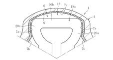
ワンショット焼入れは、図6に示すように、外側継手部材1の3つのトラック溝6にそれぞれ嵌入される加熱部17a、17a、17aを有する高周波誘導加熱コイル17を備えた高周波加熱装置を用いる。このため、ローラ案内面7aを継手軸方向全域にわたって一度に加熱急冷が可能となる。また、前記特許文献1では、大内径部7cの内面に硬化層を形成させないため、誘導コイルに非導電性のフェライトコアを装着している。このため、このような高周波加熱装置を用いることによって、図7に示すようにローラ案内面7aの表面にのみ硬化層Sを形成することができる。
また、移動焼入法は、図8から図10に示す高周波加熱装置を用いる。この高周波加熱装置は、三つ葉のクローバ状に巻設されたコイル18と、このコイル18に付設される冷却ジャケット19とを備える。コイル18は、周方向に沿って約120°ピッチで配置される略三角形状の加熱部18a、18a、18aを備える。加熱部18aはローラ案内面7aに相対面する湾曲部20a、20aと、小内径部7bに対面する直線部20c、大内径部7cに対面する直線部20bとを有する。なお、冷却ジャケット19の形状はコイル18と同様の三つ葉のクローバ状である。
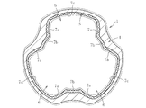
この移動焼入法では、図9に示すように、コイル18及び冷却ジャケット19を外側継手部材1のマウス部4内を軸方向に沿って移動させる。この移動に伴って、加熱面(ローラ案内面7a、小内径7b及び大内径部7c)が加熱され、この加熱に追従して冷却ジャケット19から噴出する冷却水にてこの加熱面を急冷することになる。このため、図10に示すように、ローラ案内面7a、小内径7b及び大内径部7cが加熱硬化処理され硬化層Sが形成される。
一般的なワンショット(一発)焼入法では、一時に加熱して一時に冷却するので、薄肉部等においてひずみが発生しやすくカップ入口側、中央、奥側で比較した場合、焼入れ硬化層深さ差が生じ不均一となるデメリットがある。これに対して、移動焼入れは、生じるひずみを安定させたり、焼入れ硬化層深さを制御することで均一化させる効果がある。
ところで、継手の機能を考慮すると、少なくともローラ案内面7aに硬化層が設けられていれば問題はない。しかしながら、移動焼入れを行えば、図10に示すように、ローラ案内面7a、小内径7b及び大内径部7cが加熱硬化処理され硬化層Sが形成される。
外側継手部材1の外周にはブーツバンド締め付け溝10が形成されており、この部分の肉厚は薄い。このため、この薄肉部において、硬化層Sが外周側に抜けてしまう可能性があり、この部分が強度的に脆くなる可能性がある。このため、継手の小型化が困難になる等の設計自由度が制限されるというデメリットがあった。
また、ローラ案内面7a、小内径7b及び大内径部7cが加熱硬化処理(焼入れ)されると、図11に示すように、焼入れによりマルテンサイトとなった領域が体積膨張する。このため、カップ内側では圧縮方向に応力が発生して仮想線で示すように縮み、それに伴いカップ外側では逆に引っ張り方向への応力が発生して仮想線で示すように膨らむ。これにより、外周部の疲労に対する強度が低下して、大内径を焼入しない一発焼入と比べて強度が低下するため板厚を厚くする必要があり、外側継手部材1の小型化が困難になる等の設計自由度が制限される。
そこで、本発明は斯かる実情に鑑み、高周波焼入れの移動焼入れでもって、大内径部に硬化層を形成することなく強度的に優れたトリポード型等速自在継手の外側継手部材を成形できる熱処理方法、このような熱処理方法で構成された外側継手部材及びトリポード型等速自在継手を提供しようとするものである。
本発明の第1の熱処理方法は、円周方向に向き合ったローラ案内面と両ローラ案内面間に設けられた大内径部からなるトラック溝が内周の三箇所に形成される外側継手部材に対して、高周波誘導加熱コイルが相対的に軸方向に移動する移動焼入れにて、外側継手部材のローラ案内面に硬化層を形成するための熱処理方法であって、前記大内径部に対して冷却水を噴射して大内径部の昇温を抑制しつつ高周波誘導加熱コイルによる移動焼入れを行うものである。
本発明の第1の熱処理方法によれば、大内径部に対して冷却水を噴射して大内径部の昇温を抑制することができる。このため、高周波誘導加熱コイルによる移動焼入れ時に、この部位(大内径部)においては、オーステナイト化温度まで上昇するのを防止できる。
本発明の熱処理装置は、円周方向に向き合ったローラ案内面と両ローラ案内面間に設けられた大内径部からなるトラック溝が内周の三箇所に形成される外側継手部材に対して、高周波誘導加熱コイルが相対的に軸方向に移動する移動焼入れにて、外側継手部材のローラ案内面に硬化層を形成するための熱処理装置であって、大内径部に対して冷却水を噴射して大内径部の昇温を抑制する大内径部用冷却手段を備えたものである。
本発明の熱処理装置によれば、大内径部用冷却手段にて大内径部に対して冷却水を噴射することができる。このため、高周波誘導加熱コイルによる移動焼入れ時に、この部位(大内径部)においては、オーステナイト化温度まで上昇するのを防止できる。
前記大内径部用冷却手段は、前記大内径部の近傍に配置される大内径部用冷却ジャケットを備え、大内径部用冷却ジャケットには、前記大内径部に冷却水を噴射するための噴射口が開設されているもので構成できる。大内径部用冷却ジャケットが配置されたものであれば、このジャケットから大内径部に冷却水を安定して噴射することができる。
前記高周波誘導加熱コイルにおける大内径部対応部に、前記大内径部用冷却ジャケットが配置される凹部を設けるのが好ましい。前記大内径部用冷却ジャケットが非磁性体にて構成されていても、絶縁材にて構成されていてもよい。大内径部用冷却ジャケットが非磁性体や絶縁材であれば、高周波誘導加熱コイルに発生する磁力線を受けても誘導加熱されることがないため、ジャケット自体が発熱することが防げる。
大内径部用冷却手段は、大内径部への冷却水の噴射量を制御する流量調整手段を備えたものとするのが好ましい。流量調整手段を備えたものであれば、冷却条件の変更が可能となる。また、大内径部用冷却手段は、大内径部への冷却水の噴射のタイミングを制御するタイミング制御手段を備えたものであってもよい。タイミング制御手段を備えたものでは、冷却水の噴射を任意のタイミングで行うことができる。
前記大内径部用冷却手段は、大内径部に対して冷却する範囲と、冷却しない範囲を形成するものであってもよい。このようなものでは、大内径部全体を冷却したり、大内径部の一部を冷却しないようにできる。
前記大内径部用冷却手段は、冷却水の噴射位置の変更が可能であるものであってもよい。このように変更が可能なものでは、冷却範囲を変更できる。
熱処理方法として、前記熱処理装置を用いることができる。
トリポード型等速自在継手の外側継手部材は、前記熱処理方法にて処理されたものとできる。
本発明のトリポード型等速自在継手は、前記外側継手部材と、前記外側継手部材内に配置され半径方向に突出した3つの脚軸を備えたトリポード部材と、前記トリポード部材の各脚軸に装着され前記ローラ案内面に沿って前記外側継手部材の軸方向に案内されるローラ部材とを備えたものである。
本発明では、外側継手部材の大内径部に未焼部分を設けることができ、強度的に優れた大内径部を構成できるとともに、他の部位においては安定した硬化層を形成できる。
大内径部用冷却ジャケットが大内径部の近傍に配置されたものであれば、このジャケットから大内径部に冷却水を安定して噴射することができ、大内径部に安定して未焼部分を形成することができる。凹部を設けたことによって、装置のコンパクト化を図ることができる。
大内径部用冷却ジャケットが磁性体や絶縁材であれば、高周波誘導加熱コイルに発生する磁力線を受けても誘導加熱されることがないため、大内径部に安定して未焼部分を形成することができる。
流量調整手段を備えたものであれば、冷却条件の変更が可能となり、加熱処理する製品に対応して未焼部分を形成することができる。また、タイミング制御手段を備えたものでは、冷却水の噴射を任意のタイミングで行うことができ、作業性の向上を図ることができる。
内径部用冷却手段は、大内径部に対して冷却する範囲と、冷却しない範囲を形成するようにできるものであれば、大内径部全体を冷却したり、大内径部の一部を冷却しないようにでき、最適範囲に未焼部分を形成できる。
前記大内径部用冷却手段は、冷却水の噴射位置の変更が可能であれば、各製品に応じて最適範囲に未焼部分を形成できる。
本発明のトリポード型等速自在継手の外側継手部材は、前記熱処理方法にて処理されているものであるので、強度的に安定したものとなって、耐久性に優れる。
本発明のトリポード型等速自在継手は、前記熱処理方法にて処理されている外側継手部材を用いるので、耐久性に優れた高品質のトリポード型等速自在継手となり、しかも、継手の小型化等の設計自由度が大きくなる。また、トリポード型等速自在継手としては、種々のタイプのものに適用できる。
以下、本発明の実施形態を図面に従って説明する。
図1は本発明に係る熱処理方法にて熱硬化処理を行っている外側継手部材の要部断面図を示し、この外側継手部材は図2と図3に示すようなトリポード型等速自在継手に用いられる。トリポード型等速自在継手は、外側継手部材31と、内側継手部材としてのトリポード部材32と、トルク伝達部材33とを備える。
外側継手部材31は一端にて開口したカップ状のマウス部34と、マウス部34の底壁から突設されるステム部35を有し、内周の円周方向三等分位置に軸方向に延びるトラック溝36が形成してある。マウス部34は、横断面で見ると、大径部34aと小径部34bが交互に現れる非円筒形状である。すなわち、マウス部34は、大径部34aと小径部34bとを形成することによって、その内周面に、軸方向に延びる3本の前記トラック溝36が形成される。
各トラック溝36の円周方向で向き合った側壁にローラ案内面(ローラ摺接面)37、37が形成される。また、内径面においては、円周方向に交互に現れる小内径部42と大内径部43をローラ案内面37で接続した3弁の花冠状を呈している。すなわち、外側継手部材31は、円周方向に向き合ったローラ案内面37と両ローラ案内面37,37間に設けられた大内径部43からなるトラック溝36が内周の三箇所に形成されるものである。
トリポード部材32はボス38と脚軸39とを備える。ボス38にはシャフト(図示省略)とトルク伝達可能に結合するスプラインまたはセレーション孔41が形成してある。脚軸39はボス38の円周方向三等分位置から半径方向に突出している。
各脚軸39は、円筒形外周面44と、軸端付近に形成された環状の輪溝46を備えている。脚軸39の外周に複数の針状ころ47を介して回転自在にトルク伝達部材33を構成するローラ部材50を外嵌している。脚軸39の円筒形外周面44は針状ころ47の内側軌道面を提供する。ローラ部材50の内周面は円筒形で、針状ころ47の外側軌道面を提供する。
針状ころ47は脚軸39の半径方向で見た外側の端面にてアウタ・ワッシャ51と接し、反対側の端面にてインナ・ワッシャ52と接している。アウタ・ワッシャ51は輪溝46に装着されたサークリップ53によって軸方向移動を規制されているため、結局、針状ころ47も軸方向移動を規制される。
ところで、外側継手部材31の開口部は図示省略のブーツによって密封される。そのため、外側継手部材31の外径面の開口部側には、凹溝を有するブーツ装着部が形成される。そして、このブーツ装着部にブーツが外嵌され、ブーツバンドにて締め付けることによって、ブーツが外側継手部材31のブーツ装着部に装着される。
ところで、外側継手部材31のマウス部34の内径面には硬化層S(図1及び図2参照)が形成されている。この場合、大内径部43には未焼き部55が形成されている。なお、図例では、未焼き部55は大内径部43全体ではなく、周方向端部には硬化層Sが形成されている。未焼き部55は、後述する大内径部用冷却手段M1(図4参照)を用いて形成されることになる。
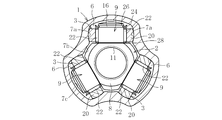
この硬化層Sの形成には図1に示す高周波誘導加熱コイル56を有する高周波加熱装置が用いられる。高周波誘導加熱コイル56は、トラック溝36内に嵌合される3つの嵌合部56A、56B、56Cと、小内径部42に対向する直線部57A、57B、57Cとを備える。なお、直線部57Cは、第1の嵌合部56Aに連設される分岐部58と、第3の嵌合部56Bに連設される分岐部59とからなる。
また、各嵌合部56A、56B、56Cは、ローラ案内面37に相対向する湾曲部60,60と、大内径部43に相対向する直線部61とからなる。そして、直線部61には、大内径部対向面に凹部62が設けられている。この凹部62に、前記大内径部用冷却手段M1の大内径部冷却ジャケット65が配置される。
大内径部冷却ジャケット65は、扁平矩形中空体にて構成され、その大内径部対向壁の対向面が、大内径部43に対面するように凸曲面66とされている。また、凹部62には絶縁板67が配置され、この絶縁板67を介して大内径部冷却ジャケット65が凹部62に嵌合されている。そして、内径部対向壁に複数個の冷却水噴射口68が設けられている。すなわち、この大内径部冷却ジャケット65の冷却水噴射口68を介して大内径部43に噴射される。
大内径部冷却ジャケット65としては、真鍮、銅等の非磁性材にて構成したり、エポキシ等の樹脂の絶縁材料にて構成したりできる。
本熱処理装置の制御部は、図4に示すように、高周波誘導加熱コイル56への通電を制御する制御手段80を備える。この制御手段80にて、前記大内径部用冷却手段M1を制御する。すなわち、大内径部冷却ジャケット65には、その噴出口68にそれぞれ配管が接続され、この配管に、制御手段80からの制御信号にて開閉動作するバルブ手段が設けられている。そして、この制御手段80のタイミング制御手段82の制御によって、噴出口68から冷却水を任意のタイミングで噴射することができる。なお、バルブ手段を、流量の調整が可能な電動弁等にて構成することによって、流量調整手段81を形成するようにしてもよい。制御手段80は例えば、マイクロコンピュータ等にて構成される。
ところで、高周波電流の流れているコイルの近くに焼入れに必要な部分を近づけると、電磁誘導作用により誘導起電力が生ずる。この電磁誘導作用により、ジュール熱が発生することを利用して、伝導性物体を加熱する原理を応用した焼入れ方法が高周波焼入れである。このため、高周波焼入れの場合、上記原理に基づき、鋼を焼入れ温度まで急速加熱し、急冷する操作を行う。そこで、この高周波加熱装置には、図4に示すように、熱処理した部位を冷却するための内周冷却手段M2が設けられている。内周冷却手段M2は、高周波誘導加熱コイル56の下方位置に配置される内周冷却用ジャケットを備える。すなわち、内周冷却用ジャケットは、外側継手部材31の内周に冷却水を噴射して、焼入れ工程での冷却を行うものである。
次に前記のように構成された高周波加熱装置を用いた加熱処理方法を説明する。大内径部冷却ジャケット65及び図示省略の内周冷却用ジャケットを備えた高周波誘導加熱コイル56を外側継手部材31に挿入して、高周波誘導加熱コイル56に高周波電流を流すことによって、外側継手部材31の内周を加熱する。すなわち、高周波誘導加熱コイル56には、図示省略の高周波電源から高周波電流が流されることになる。この際、高周波電流は、嵌合部56A→嵌合部56B→嵌合部56Cと流れることになる。但し、交流電流のため流れる向きは交互となる。このように、高周波電流が流れることによって、電磁誘導作用により誘導起電力が生ずる。この電磁誘導作用により、ジュール熱が発生して、外側継手部材31のローラ案内面37等を加熱することができる。
ところで、前記高周波誘導加熱コイル56の各嵌合部56A、56B、56Cには、図1に示すように、大内径部冷却ジャケット65が配置されており、高周波誘導加熱コイル56への高周波電流の通電によるローラ案内面37等の加熱開始と同時、又は、この加熱よりも僅かに早いタイミングでこの大内径部冷却ジャケット65の噴出口68から冷却水が大内径部43に噴射される。すなわち、高周波電流の通電は、前記制御手段80の通電制御部にて制御され、冷却水の噴射のタイミングは制御手段80のタイミング手段82にて制御される。
このように、冷却水が噴射されることによって、この大内径部43においては昇温が抑制される。しかしながら、大内径部43以外の部位では、ローラ案内面37及び小内径部42では、この大内径部冷却ジャケット65の冷却水に影響されることなく、加熱されることになって、オーステナイト化温度まで上昇する。また、高周波誘導加熱コイル56をマウス部の開口部側から順次マウス部の奥側に移動させる。これによって、ローラ案内面37及び小内径部42等は開口部側から奥側までが加熱される。すなわち、高周波誘導加熱コイル56の相対移動に従って順次ローラ案内面37等を加熱し、冷却流体で加熱部を急冷することになって、高周波焼入れを施すことになる。
このように、この高周波加熱装置を用いれば、大内径部43が加熱されず、この部位(大内径部)においては、オーステナイト化温度まで上昇するのを防止できる。したがって、外側継手部材31の大内径部43に未焼き部55を設けることができ、強度的に優れた大内径部43を構成できるとともに、他の部位においては安定した硬化層Sを形成できる。
大内径部用冷却ジャケット65が大内径部43の近傍に配置されているので、このジャケット65から大内径部43に冷却水を安定して噴射することができ、大内径部43に安定して未焼き部55を形成することができる。また、大内径部用冷却ジャケット65は、コイル56における大内径部対応部に、設けられた凹部62に嵌合するものであるので、装置のコンパクト化を図ることができる。
大内径部用冷却ジャケット65が磁性体や絶縁材であれば、高周波誘導加熱コイル56に発生する磁力線を受けても誘導加熱されることがないため、大内径部43に安定して未焼き部55を形成することができる。
流量調整手段81を備えたものであれば、冷却条件の変更が可能となり、加熱処理する製品に対応して未焼部分を形成することができる。また、タイミング制御手段82を備えたものでは、冷却水の噴射を任意のタイミングで行うことができ、作業性の向上を図ることができる。
ところで、大内径部43に対して冷却する範囲と、冷却しない範囲を形成するようにできる。このようなものを用いれば、大内径部43全体を冷却したり、大内径部43の一部を冷却しないようにでき、最適範囲に未焼部分を形成できる。
前記大内径部用冷却手段M1は、冷却水の噴射位置の変更が可能であれば、各製品に応じて最適範囲に未焼部分を形成できる。
このように硬化層Sが構成された外側継手部材31は、前記熱処理方法にて処理されているものであるので、強度的に安定したものとなって、耐久性に優れる。また、このように成形された外側継手部材31は、図2と図3に示すようなトリポード型等速自在継手を組み立てることができる。このため、このトリポード型等速自在継手は、前記熱処理方法にて処理されている外側継手部材を用いるので、耐久性に優れた高品質のトリポード型等速自在継手となり、しかも、継手の小型化等の設計自由度が大きくなる。
ところで、図1等に示すように、大内径部43に対して焼入れしない方法として、冷却水を用いることなく、図5に示すように、ジャケット65に代えて、強磁性体コア90を凹部に嵌合させるものであってもよい。この強磁性体コア90によって、高周波誘導加熱コイル56にて発生する磁力線が遮断されることになる。すなわち、強磁性体コア90は、透磁率の高い材質でコイルに取り付けて磁力線をワークに集中させてパワーを増強する効果がある一方、磁力線を遮断し、目的外の加熱を防ぐために使われる。このため、本発明のように、トリポード型等速自在継手の外側継手部材31の内径面の加熱硬化処理に用いれば、従来の移動焼きでは不可能であった大内径部43に未焼き部55を設けることができる。
ところが、このような強磁性体コア90を用いたものでは、トラック面(ローラ案内面)37における大内径部側の範囲Hにおいても、発生する磁力線が、この強磁性体コア90によって弱くなるおそれがある。このように、弱くなれば、図5に示すように、この範囲Hにおいて形成される硬化層が浅くなるおそれがある。このため、強磁性体コア90を用いる場合、このことを考慮して、強磁性体コア90の形状や配置等を設定する必要がある。
これに対して、大内径部43に冷却水を噴射するものでは、磁束を遮断しないため、トラック面(ローラ案内面)37での磁束の減衰が生じない。このため、大内径部43に未焼き部55を設けたとしても、ローラ案内面37の硬化層が浅く(薄く)なりにくい利点がある。
前記実施形態では、大内径部43の周方向中央部において軸方向に沿って未焼き部55を形成するものであったが、全大内径部43を未焼き部55とするものであっても、大内径部43の継手奥側に未焼き部55を設けないものであってもよい。すなわち、大内径部43において、ブーツ装着部に対応する開口部(入口部)側、及び常用使用する位置での部位を除いた継手奥側を硬化層Sが設けられていてもよい。これは、大内径部43の継手奥側に硬化層が設けられていても強度に及ぼす影響が少ないからである。また、小内径部42に対しては、硬化層Sを設けても設けなくてもよく、ローラ案内面37にのみ硬化層Sを設けるものであってもよい。このため、外側継手部材31としての機能を損なうことなく、最適の範囲において硬化層Sを形成することができる。
以上、本発明の実施形態につき説明したが、本発明は前記実施形態に限定されることなく種々の変形が可能であって、例えば、大内径部用冷却ジャケット65の冷却水供給経路と、内周冷却用ジャケットの冷却水供給経路とを別系統としても同一系統としてもよい。また、大内径部用冷却ジャケット65の噴射口68の数、口径、配置位置等を種々変更することができる。このため、大内径部用冷却ジャケット65が交換可能なものであれば、噴射口68の数、口径、配置位置等が相違する複数種のジャケット65を用意するようにできる。また、前記実施形態では、脚軸39の円筒状の外周面に複数の針状ころ47を介して回転可能に外嵌したローラからなるいわゆるシングルローラタイプであったが、内側ローラと外側ローラとを備えたいわゆるダブルローラタイプ等の他のタイプであってもよい。
トリポード型等速自在継手の外側継手部材の構造等を考慮し、かつ、移動焼入れの利点をいかしつつ、最適な硬化層形成が可能な焼入れ方法(熱処理方法)を提供する。この熱処理方法によって、強度的に安定したトリポード型等速自在継手の外側継手部材の製造を可能とする。
31 外側継手部材
32 トリポード部材
33 トルク伝達部材
36 トラック溝
37 ローラ案内面
39 脚軸
42 小内径部
43 大内径部
55 未焼き部
56 高周波誘導加熱コイル
62 凹部
65 大内径部用冷却ジャケット
81 流量調整手段
82 タイミング制御手段
M1 大内径部用冷却手段
S 硬化層
32 トリポード部材
33 トルク伝達部材
36 トラック溝
37 ローラ案内面
39 脚軸
42 小内径部
43 大内径部
55 未焼き部
56 高周波誘導加熱コイル
62 凹部
65 大内径部用冷却ジャケット
81 流量調整手段
82 タイミング制御手段
M1 大内径部用冷却手段
S 硬化層
Claims (13)
- 円周方向に向き合ったローラ案内面と両ローラ案内面間に設けられた大内径部からなるトラック溝が内周の三箇所に形成される外側継手部材に対して、高周波誘導加熱コイルが相対的に軸方向に移動する移動焼入れにて、外側継手部材のローラ案内面に硬化層を形成するための熱処理方法であって、前記大内径部に対して冷却水を噴射して大内径部の昇温を抑制しつつ高周波誘導加熱コイルによる移動焼入れを行うことを特徴とする熱処理方法。
- 円周方向に向き合ったローラ案内面と両ローラ案内面間に設けられた大内径部からなるトラック溝が内周の三箇所に形成される外側継手部材に対して、高周波誘導加熱コイルが相対的に軸方向に移動する移動焼入れにて、外側継手部材のローラ案内面に硬化層を形成するための熱処理装置であって、大内径部に対して冷却水を噴射して大内径部の昇温を抑制する大内径部用冷却手段を備えたことを特徴とする熱処理装置。
- 前記大内径部用冷却手段は、前記大内径部の近傍に配置される大内径部用冷却ジャケットを備え、大内径部用冷却ジャケットには、前記大内径部に冷却水を噴射するための噴射口が開設されていることを特徴とする請求項2に記載の熱処理装置。
- 前記高周波誘導加熱コイルにおける大内径部対応部に、前記大内径部用冷却ジャケットが配置される凹部を設けたことを特徴とする請求項3に記載の熱処理装置。
- 前記大内径部用冷却ジャケットが非磁性体にて構成されていることを特徴とする請求項3又は請求項4に記載の熱処理装置。
- 前記大内径部用冷却ジャケットが絶縁材にて構成されていることを特徴とする請求項3又は請求項4に記載の熱処理装置。
- 前記大内径部用冷却手段は、大内径部への冷却水の噴射量を制御する流量調整手段を備えたことを特徴とする請求項2~請求項6のいずれか1項に記載の熱処理装置。
- 前記大内径部用冷却手段は、大内径部への冷却水の噴射のタイミングを制御するタイミング制御手段を備えたことを請求項2~請求項6のいずれか1項に記載の特徴とする熱処理装置。
- 前記大内径部用冷却手段は、大内径部に対して冷却する範囲と、冷却しない範囲を形成することを特徴とする請求項2~請求項6のいずれか1項に記載の熱処理装置。
- 前記大内径部用冷却手段は、冷却水の噴射位置の変更が可能であることを特徴とする請求項2~請求項6のいずれか1項に記載の熱処理装置。
- 前記請求項2~請求項10のいずれか1項に記載の熱処理装置を用いることを特徴とする熱処理方法。
- 前記請求項1又は請求項11に記載の熱処理方法にて処理されたことを特徴とするトリポード型等速自在継手の外側継手部材。
- 請求項12に記載の外側継手部材と、前記外側継手部材内に配置され半径方向に突出した3つの脚軸を備えたトリポード部材と、前記トリポード部材の各脚軸に装着され前記ローラ案内面に沿って前記外側継手部材の軸方向に案内されるローラ部材とを備えたことを特徴とするトリポード型等速自在継手。
Applications Claiming Priority (2)
| Application Number | Priority Date | Filing Date | Title |
|---|---|---|---|
| JP2011132094A JP5813385B2 (ja) | 2011-06-14 | 2011-06-14 | 熱処理方法及び熱処理装置 |
| JP2011-132094 | 2011-06-14 |
Publications (1)
| Publication Number | Publication Date |
|---|---|
| WO2012172940A1 true WO2012172940A1 (ja) | 2012-12-20 |
Family
ID=47356934
Family Applications (1)
| Application Number | Title | Priority Date | Filing Date |
|---|---|---|---|
| PCT/JP2012/063176 Ceased WO2012172940A1 (ja) | 2011-06-14 | 2012-05-23 | 熱処理方法、外側継手部材、及びトリポード型等速自在継手 |
Country Status (2)
| Country | Link |
|---|---|
| JP (1) | JP5813385B2 (ja) |
| WO (1) | WO2012172940A1 (ja) |
Cited By (2)
| Publication number | Priority date | Publication date | Assignee | Title |
|---|---|---|---|---|
| EP3225865A1 (en) * | 2016-03-25 | 2017-10-04 | Steering Solutions IP Holding Corporation | Textured ball tracks in tripot type housings |
| US12331797B2 (en) | 2020-05-26 | 2025-06-17 | Aircraft Gear Corporation | Method of carburizing driveline components |
Families Citing this family (1)
| Publication number | Priority date | Publication date | Assignee | Title |
|---|---|---|---|---|
| CN105349737A (zh) * | 2015-11-16 | 2016-02-24 | 中钢集团邢台机械轧辊有限公司 | 双频三效冷轧辊感应淬火工艺 |
Citations (3)
| Publication number | Priority date | Publication date | Assignee | Title |
|---|---|---|---|---|
| JPS58213828A (ja) * | 1982-06-03 | 1983-12-12 | Denki Kogyo Kk | 有底筒状体内面の高周波焼入方法 |
| JPS59129866U (ja) * | 1983-02-19 | 1984-08-31 | 高周波熱錬株式会社 | 筒体焼入台 |
| JP2002080914A (ja) * | 2000-09-08 | 2002-03-22 | Denki Kogyo Co Ltd | 不等肉厚部を有する筒状体内面の高周波移動焼入方法とその高周波コイル |
Family Cites Families (3)
| Publication number | Priority date | Publication date | Assignee | Title |
|---|---|---|---|---|
| JPS6050112A (ja) * | 1983-08-26 | 1985-03-19 | Nissan Motor Co Ltd | 部材の高周波焼入方法 |
| JP3878710B2 (ja) * | 1996-11-15 | 2007-02-07 | 有限会社フジ技研 | 有底筒状ワークの移動焼入装置及び移動焼入方法 |
| JP4298392B2 (ja) * | 2003-06-16 | 2009-07-15 | Ntn株式会社 | 等速自在継手 |
-
2011
- 2011-06-14 JP JP2011132094A patent/JP5813385B2/ja not_active Expired - Fee Related
-
2012
- 2012-05-23 WO PCT/JP2012/063176 patent/WO2012172940A1/ja not_active Ceased
Patent Citations (3)
| Publication number | Priority date | Publication date | Assignee | Title |
|---|---|---|---|---|
| JPS58213828A (ja) * | 1982-06-03 | 1983-12-12 | Denki Kogyo Kk | 有底筒状体内面の高周波焼入方法 |
| JPS59129866U (ja) * | 1983-02-19 | 1984-08-31 | 高周波熱錬株式会社 | 筒体焼入台 |
| JP2002080914A (ja) * | 2000-09-08 | 2002-03-22 | Denki Kogyo Co Ltd | 不等肉厚部を有する筒状体内面の高周波移動焼入方法とその高周波コイル |
Cited By (2)
| Publication number | Priority date | Publication date | Assignee | Title |
|---|---|---|---|---|
| EP3225865A1 (en) * | 2016-03-25 | 2017-10-04 | Steering Solutions IP Holding Corporation | Textured ball tracks in tripot type housings |
| US12331797B2 (en) | 2020-05-26 | 2025-06-17 | Aircraft Gear Corporation | Method of carburizing driveline components |
Also Published As
| Publication number | Publication date |
|---|---|
| JP2013002496A (ja) | 2013-01-07 |
| JP5813385B2 (ja) | 2015-11-17 |
Similar Documents
| Publication | Publication Date | Title |
|---|---|---|
| JP6012981B2 (ja) | 熱処理方法 | |
| JP5813385B2 (ja) | 熱処理方法及び熱処理装置 | |
| JP6427391B2 (ja) | 焼入れ装置及び焼入れ方法 | |
| JP5857020B2 (ja) | 外側継手部材の熱処理装置及び外側継手部材の製造方法 | |
| JP2010138951A (ja) | ボールねじおよびその製造方法 | |
| JP6586924B2 (ja) | カムシャフトの高周波焼入れ方法 | |
| JP2000068043A (ja) | テーパー体の誘導加熱コイル | |
| CN104498867A (zh) | 一种内孔渗碳处理感应淬火设备及方法 | |
| JP3676972B2 (ja) | クランクシャフトの高周波焼入冷却方法とその装置 | |
| JP5896106B2 (ja) | 高周波熱処理装置及び高周波熱処理方法 | |
| JP2004292853A (ja) | 棒状部材の高周波焼入方法とその装置 | |
| JP5346368B2 (ja) | 高周波誘導加熱コイル | |
| JP5129494B2 (ja) | 高周波誘導加熱コイル | |
| JP6026096B2 (ja) | 外側継手部材の製造方法 | |
| JP2010108602A (ja) | 高周波誘導加熱装置 | |
| JP2002167618A5 (ja) | 軸付球状体の誘導加熱コイルおよび焼入装置 | |
| JP5680452B2 (ja) | 熱処理方法、外側継手部材、及びトリポード型等速自在継手 | |
| JP2004010928A (ja) | 内周面焼入装置 | |
| JPH0619193Y2 (ja) | 段付き軸加熱用コイル | |
| JP2008169923A (ja) | 等速自在継手外輪の焼戻し加工方法及び誘導加熱装置 | |
| CN110016545B (zh) | 一种凸缘类零件专用淬火感应器的配用尺寸确定方法 | |
| US12595524B2 (en) | Induction hardening system | |
| JP2005347069A (ja) | 誘導加熱方法及び誘導加熱コイル | |
| JP2010024515A (ja) | 誘導加熱装置 | |
| JP2007247025A (ja) | 誘導加熱コイルとコアの配置方法及コア |
Legal Events
| Date | Code | Title | Description |
|---|---|---|---|
| 121 | Ep: the epo has been informed by wipo that ep was designated in this application |
Ref document number: 12800233 Country of ref document: EP Kind code of ref document: A1 |
|
| NENP | Non-entry into the national phase |
Ref country code: DE |
|
| 122 | Ep: pct application non-entry in european phase |
Ref document number: 12800233 Country of ref document: EP Kind code of ref document: A1 |