WO2012172684A1 - Dispositif de pompe à chaleur, climatiseur et réfrigérateur - Google Patents
Dispositif de pompe à chaleur, climatiseur et réfrigérateur Download PDFInfo
- Publication number
- WO2012172684A1 WO2012172684A1 PCT/JP2011/063933 JP2011063933W WO2012172684A1 WO 2012172684 A1 WO2012172684 A1 WO 2012172684A1 JP 2011063933 W JP2011063933 W JP 2011063933W WO 2012172684 A1 WO2012172684 A1 WO 2012172684A1
- Authority
- WO
- WIPO (PCT)
- Prior art keywords
- frequency
- period
- heat pump
- heating
- pump device
- Prior art date
Links
Images


Classifications
-
- F—MECHANICAL ENGINEERING; LIGHTING; HEATING; WEAPONS; BLASTING
- F25—REFRIGERATION OR COOLING; COMBINED HEATING AND REFRIGERATION SYSTEMS; HEAT PUMP SYSTEMS; MANUFACTURE OR STORAGE OF ICE; LIQUEFACTION SOLIDIFICATION OF GASES
- F25B—REFRIGERATION MACHINES, PLANTS OR SYSTEMS; COMBINED HEATING AND REFRIGERATION SYSTEMS; HEAT PUMP SYSTEMS
- F25B49/00—Arrangement or mounting of control or safety devices
- F25B49/02—Arrangement or mounting of control or safety devices for compression type machines, plants or systems
- F25B49/025—Motor control arrangements
-
- F—MECHANICAL ENGINEERING; LIGHTING; HEATING; WEAPONS; BLASTING
- F04—POSITIVE - DISPLACEMENT MACHINES FOR LIQUIDS; PUMPS FOR LIQUIDS OR ELASTIC FLUIDS
- F04B—POSITIVE-DISPLACEMENT MACHINES FOR LIQUIDS; PUMPS
- F04B49/00—Control, e.g. of pump delivery, or pump pressure of, or safety measures for, machines, pumps, or pumping installations, not otherwise provided for, or of interest apart from, groups F04B1/00 - F04B47/00
- F04B49/06—Control using electricity
-
- F—MECHANICAL ENGINEERING; LIGHTING; HEATING; WEAPONS; BLASTING
- F04—POSITIVE - DISPLACEMENT MACHINES FOR LIQUIDS; PUMPS FOR LIQUIDS OR ELASTIC FLUIDS
- F04C—ROTARY-PISTON, OR OSCILLATING-PISTON, POSITIVE-DISPLACEMENT MACHINES FOR LIQUIDS; ROTARY-PISTON, OR OSCILLATING-PISTON, POSITIVE-DISPLACEMENT PUMPS
- F04C28/00—Control of, monitoring of, or safety arrangements for, pumps or pumping installations specially adapted for elastic fluids
- F04C28/06—Control of, monitoring of, or safety arrangements for, pumps or pumping installations specially adapted for elastic fluids specially adapted for stopping, starting, idling or no-load operation
-
- F—MECHANICAL ENGINEERING; LIGHTING; HEATING; WEAPONS; BLASTING
- F25—REFRIGERATION OR COOLING; COMBINED HEATING AND REFRIGERATION SYSTEMS; HEAT PUMP SYSTEMS; MANUFACTURE OR STORAGE OF ICE; LIQUEFACTION SOLIDIFICATION OF GASES
- F25B—REFRIGERATION MACHINES, PLANTS OR SYSTEMS; COMBINED HEATING AND REFRIGERATION SYSTEMS; HEAT PUMP SYSTEMS
- F25B30/00—Heat pumps
- F25B30/02—Heat pumps of the compression type
-
- H—ELECTRICITY
- H02—GENERATION; CONVERSION OR DISTRIBUTION OF ELECTRIC POWER
- H02M—APPARATUS FOR CONVERSION BETWEEN AC AND AC, BETWEEN AC AND DC, OR BETWEEN DC AND DC, AND FOR USE WITH MAINS OR SIMILAR POWER SUPPLY SYSTEMS; CONVERSION OF DC OR AC INPUT POWER INTO SURGE OUTPUT POWER; CONTROL OR REGULATION THEREOF
- H02M1/00—Details of apparatus for conversion
- H02M1/44—Circuits or arrangements for compensating for electromagnetic interference in converters or inverters
-
- H—ELECTRICITY
- H02—GENERATION; CONVERSION OR DISTRIBUTION OF ELECTRIC POWER
- H02M—APPARATUS FOR CONVERSION BETWEEN AC AND AC, BETWEEN AC AND DC, OR BETWEEN DC AND DC, AND FOR USE WITH MAINS OR SIMILAR POWER SUPPLY SYSTEMS; CONVERSION OF DC OR AC INPUT POWER INTO SURGE OUTPUT POWER; CONTROL OR REGULATION THEREOF
- H02M7/00—Conversion of ac power input into dc power output; Conversion of dc power input into ac power output
- H02M7/42—Conversion of dc power input into ac power output without possibility of reversal
- H02M7/44—Conversion of dc power input into ac power output without possibility of reversal by static converters
- H02M7/48—Conversion of dc power input into ac power output without possibility of reversal by static converters using discharge tubes with control electrode or semiconductor devices with control electrode
- H02M7/53—Conversion of dc power input into ac power output without possibility of reversal by static converters using discharge tubes with control electrode or semiconductor devices with control electrode using devices of a triode or transistor type requiring continuous application of a control signal
- H02M7/537—Conversion of dc power input into ac power output without possibility of reversal by static converters using discharge tubes with control electrode or semiconductor devices with control electrode using devices of a triode or transistor type requiring continuous application of a control signal using semiconductor devices only, e.g. single switched pulse inverters
- H02M7/5387—Conversion of dc power input into ac power output without possibility of reversal by static converters using discharge tubes with control electrode or semiconductor devices with control electrode using devices of a triode or transistor type requiring continuous application of a control signal using semiconductor devices only, e.g. single switched pulse inverters in a bridge configuration
- H02M7/53871—Conversion of dc power input into ac power output without possibility of reversal by static converters using discharge tubes with control electrode or semiconductor devices with control electrode using devices of a triode or transistor type requiring continuous application of a control signal using semiconductor devices only, e.g. single switched pulse inverters in a bridge configuration with automatic control of output voltage or current
- H02M7/53875—Conversion of dc power input into ac power output without possibility of reversal by static converters using discharge tubes with control electrode or semiconductor devices with control electrode using devices of a triode or transistor type requiring continuous application of a control signal using semiconductor devices only, e.g. single switched pulse inverters in a bridge configuration with automatic control of output voltage or current with analogue control of three-phase output
- H02M7/53876—Conversion of dc power input into ac power output without possibility of reversal by static converters using discharge tubes with control electrode or semiconductor devices with control electrode using devices of a triode or transistor type requiring continuous application of a control signal using semiconductor devices only, e.g. single switched pulse inverters in a bridge configuration with automatic control of output voltage or current with analogue control of three-phase output based on synthesising a desired voltage vector via the selection of appropriate fundamental voltage vectors, and corresponding dwelling times
-
- F—MECHANICAL ENGINEERING; LIGHTING; HEATING; WEAPONS; BLASTING
- F04—POSITIVE - DISPLACEMENT MACHINES FOR LIQUIDS; PUMPS FOR LIQUIDS OR ELASTIC FLUIDS
- F04C—ROTARY-PISTON, OR OSCILLATING-PISTON, POSITIVE-DISPLACEMENT MACHINES FOR LIQUIDS; ROTARY-PISTON, OR OSCILLATING-PISTON, POSITIVE-DISPLACEMENT PUMPS
- F04C2240/00—Components
- F04C2240/40—Electric motor
- F04C2240/403—Electric motor with inverter for speed control
-
- F—MECHANICAL ENGINEERING; LIGHTING; HEATING; WEAPONS; BLASTING
- F04—POSITIVE - DISPLACEMENT MACHINES FOR LIQUIDS; PUMPS FOR LIQUIDS OR ELASTIC FLUIDS
- F04C—ROTARY-PISTON, OR OSCILLATING-PISTON, POSITIVE-DISPLACEMENT MACHINES FOR LIQUIDS; ROTARY-PISTON, OR OSCILLATING-PISTON, POSITIVE-DISPLACEMENT PUMPS
- F04C2270/00—Control; Monitoring or safety arrangements
- F04C2270/70—Safety, emergency conditions or requirements
- F04C2270/701—Cold start
-
- F—MECHANICAL ENGINEERING; LIGHTING; HEATING; WEAPONS; BLASTING
- F25—REFRIGERATION OR COOLING; COMBINED HEATING AND REFRIGERATION SYSTEMS; HEAT PUMP SYSTEMS; MANUFACTURE OR STORAGE OF ICE; LIQUEFACTION SOLIDIFICATION OF GASES
- F25B—REFRIGERATION MACHINES, PLANTS OR SYSTEMS; COMBINED HEATING AND REFRIGERATION SYSTEMS; HEAT PUMP SYSTEMS
- F25B2600/00—Control issues
- F25B2600/02—Compressor control
- F25B2600/021—Inverters therefor
-
- Y—GENERAL TAGGING OF NEW TECHNOLOGICAL DEVELOPMENTS; GENERAL TAGGING OF CROSS-SECTIONAL TECHNOLOGIES SPANNING OVER SEVERAL SECTIONS OF THE IPC; TECHNICAL SUBJECTS COVERED BY FORMER USPC CROSS-REFERENCE ART COLLECTIONS [XRACs] AND DIGESTS
- Y02—TECHNOLOGIES OR APPLICATIONS FOR MITIGATION OR ADAPTATION AGAINST CLIMATE CHANGE
- Y02B—CLIMATE CHANGE MITIGATION TECHNOLOGIES RELATED TO BUILDINGS, e.g. HOUSING, HOUSE APPLIANCES OR RELATED END-USER APPLICATIONS
- Y02B30/00—Energy efficient heating, ventilation or air conditioning [HVAC]
- Y02B30/70—Efficient control or regulation technologies, e.g. for control of refrigerant flow, motor or heating
Definitions
- the present invention relates to a heat pump device using a compressor, a refrigerator equipped with a heat pump device, and an air conditioner.
- Patent Document 1 has a problem that there is no detailed description of high-frequency low voltage, and the realization of the problem of smoothing the lubricating action inside the compressor is not shown.
- Patent Document 2 it is described that a voltage is applied by a single-phase AC power source having a high frequency of 25 kHz. Higher frequency reduces noise due to out of audible range, suppression of vibration due to loss of resonance frequency, reduction of input and temperature rise by reducing current due to winding inductance, and effects of suppressing rotation of compressor rotating part It is shown.
- Patent Document 2 is a high-frequency single-phase AC power supply, as shown in FIG. 3 of Cited Document 2, the entire off section in which all the switching elements are turned off is generated relatively long. Become. At this time, the high-frequency current is regenerated to the DC power supply without circulating the motor through the freewheeling diode, the current in the off section decays quickly, the high-frequency current does not flow efficiently to the motor, and the heating efficiency of the compressor is poor. There was a problem of becoming.
- the present invention has been made in view of the above, and obtains a heat pump device, an air conditioner, and a refrigerator that can efficiently flow a high-frequency current to an electric motor and can effectively heat a compressor. For the purpose.
- the present invention provides a compressor having a compression mechanism for compressing a refrigerant and a motor for driving the compression mechanism, a heat exchanger, and a desired voltage for the motor. And an inverter control unit that generates a PWM signal for driving the inverter, wherein the inverter control unit determines whether or not the compressor needs to be heated. , Upon receiving the heating determination unit for notifying the determination result and the notification indicating that heating is necessary, the mode shifts to a heating operation mode for heating the compressor, and the heating operation mode has two or more predetermined frequencies. And a PWM signal generation unit that generates the PWM signal so as to provide a period during which the reflux current flows based on the heating carrier signal.
- the heat pump device can efficiently flow a high-frequency current to the electric motor, and can effectively heat the compressor.
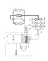
- FIG. 1 is a diagram illustrating a configuration example of the air conditioner according to the first embodiment.
- FIG. 2 is a diagram illustrating an example of a voltage command and a PWM signal generated for heating.
- FIG. 3 is a diagram showing an example of the motor current when the inverter is operated with the PWM signal as shown in FIG.
- FIG. 4 is a diagram showing a generation example of a PWM signal different from FIG.
- FIG. 5 is a diagram showing ON / OFF states of switching elements 16-1 to 16-6 in the inverter corresponding to each voltage vector.
- FIG. 6 is a diagram illustrating an example of an operation waveform when a carrier having two periods A and B is used.
- FIG. 7 is a diagram illustrating a configuration example of the air conditioner of the second embodiment.
- FIG. 8 is a diagram showing an example of operation waveforms for explaining the operation of the second embodiment.
- FIG. 9 is a diagram illustrating an example of an operation waveform when correction is performed by the PWM signal correction unit
- FIG. 1 is a diagram illustrating a configuration example of Embodiment 1 of an air conditioner according to the present invention.
- the air conditioner of the present embodiment is a separate air conditioner, and the compressor 1, the four-way valve 2, the outdoor heat exchanger 3, the expansion valve 4 and the indoor heat exchanger 5 are connected via a refrigerant pipe 6. Having a refrigeration cycle.
- a compression mechanism 7 for compressing the refrigerant and a motor 8 for operating the compression mechanism 7 are provided inside the compressor 1, a compression mechanism 7 for compressing the refrigerant and a motor 8 for operating the compression mechanism 7 are provided.
- An inverter 9 that applies a voltage to the motor 8 to drive it is electrically connected to the motor 8.
- the air conditioner of the present embodiment includes a DC power supply 14 to which the inverter 9 is connected, and a bus voltage detection unit 10 that detects a bus voltage that is a power supply voltage of the inverter 9.
- the compressor 1, the four-way valve 2, the outdoor heat exchanger 3, the expansion valve 4, the indoor heat exchanger 5, the inverter 9, the bus voltage detector 10 and the inverter controller 11 constitute a peat pump device in the air conditioner.
- the control input terminal of the inverter 9 is connected to the inverter control unit 11.
- a stagnation detection unit 12 a high-frequency AC voltage generation unit 13, a PWM (Pulse Width Modulation) signal generation unit 15, and a carrier frequency switching unit 17 are provided.
- PWM Pulse Width Modulation
- the inverter 9 has switching elements 16-1 to 16-6 connected in a bridge, and switching corresponding to each is performed by PWM signals (UP, VP, WP, UN, VN, WN) sent from the inverter control unit 11. Elements (UP for switching element 16-1, VP for switching element 16-2, WP for switching element 16-3, UN for switching element 16-4, VN for switching element 16-5, WN for switching element 16-6 Drive each one).
- the stagnation detection unit (heating determination unit) 12 based on the temperature of the refrigeration cycle, the elapsed time of the temperature, and the like, the refrigerant is in the stagnation state (liquid refrigerant is stored in the sealed case of the compressor 1. And whether or not the compressor 1 needs to be heated based on whether or not it is in the sleeping state (the heating of the compressor 1 is necessary), The determination result is notified to the high-frequency AC voltage unit 13.
- the notification is a notification indicating that heating is necessary (being in a stagnation state)
- the high-frequency AC voltage generation unit 13 shifts to the heating operation mode and supplies the motor 8 in the compressor 1 for heating.
- the voltage commands Vu *, Vv *, and Vw * are obtained based on the command value of the voltage to be applied, and the obtained voltage commands are output to the PWM signal generation unit 15.
- the PWM signal generation unit 15 generates a PWM signal at the carrier frequency designated by the carrier frequency switching unit 17 based on the voltage command.
- the inverter control unit 11 configured in this way, as described above, when the stagnation detection unit 12 detects that the refrigerant is in the stagnation state while the operation command of the compressor 1 is stopped, the operation is in the heating operation mode.
- the inverter control unit 11 generates a PWM signal for heating.
- FIG. 2 is a diagram showing an example of voltage commands (Vu *, Vv *, Vw *) and PWM signals generated for heating.
- the PWM signal generator 15 Based on the voltage commands Vu *, Vv *, and Vw * generated by the high-frequency AC voltage generator 13, the PWM signal generator 15 compares the voltage commands Vu *, Vv *, and Vw * with the carrier to generate a PWM signal. The generated voltage is applied to the motor 8 by driving the switching elements 16-1 to 16-6 of the inverter 9 by the PWM signal.
- the inverter control unit 11 When the operation command is “in operation”, the inverter control unit 11 enters the normal operation mode, the PWM signal generation unit 15 generates PWM so that the motor 8 rotates, and the switching element 16 of the inverter 9 -1 to 16-1 are operated.
- the operation of the PWM signal generation unit 15 in this case is to generate a PWM by comparing a carrier and a voltage command that is a modulated wave. The generation is performed by two-phase modulation, third-order harmonic superposition modulation, space vector, or the like. Even if the voltage command is generated by modulation or the like, there is no problem, and since it is a generally known technique, detailed description is omitted. It is assumed that the operation command is input via, for example, a remote controller (not shown) of the air conditioner or an input unit (not shown) of the indoor unit and transmitted to the inverter control unit 1.
- the carrier frequency switching unit 17 transmits the carrier frequency to the PWM signal generation unit 15 so as to switch the carrier frequency based on the operation mode information acquired from the high-frequency AC voltage generation unit 13.
- the high-frequency AC voltage generator 13 receives voltage commands Vu *, Vv *, and Vw * that change in synchronization with the timing of peaks and valleys (arrows in the figure) of the carrier (frequency is fc) in FIG. Generate.
- voltage commands that are opposite to each other in the first half and second half of the carrier can be generated.
- a in the figure indicates a voltage value when the voltage command is Hi, and when the voltage designation is Low, the voltage value is -A.
- the PWM signal generation unit 15 compares the carrier with the voltage command to generate a PWM signal, thereby outputting a PWM signal synchronized with the carrier. Is possible.
- PWM signals (UP, VP, WP) for driving the switching elements 16-1 to 16-6 are generated by comparing the voltage commands Vu *, Vv *, Vw * with the carrier. .
- 0 OFF
- 1 is defined as ON
- a voltage vector described as V0 or V7 is referred to as a zero vector, and the other is referred to as a real vector.
- UN, VN, and WN are not shown, UN and UP, VU and VN, and WU and WN are OFF when one is ON, and the other is OFF when one is OFF.
- UN and UP, VU and VN, and WU and WN are OFF when
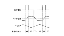
- FIG. 3 is a diagram showing an example of a motor current flowing in the motor 8 when the inverter 9 is operated by the PWM signal as shown in FIG.
- the voltage vector is the real vector V4
- the output voltage becomes a positive value and the motor current increases.
- the voltage vector is the real vector V3
- the output voltage becomes a negative value and the motor current decreases.
- a reflux current that circulates between the motor 8 and the inverter 9 flows by a diode connected in reverse parallel to the switching elements 16-1 to 16-6 of the inverter 9.
- FIG. 4 is a diagram showing an example of generating a PWM signal different from FIG.
- the difference between the example of FIG. 2 and the example of FIG. 4 is that the phase relationship of the voltage command (Vu *, Vv *, Vw *) with respect to the phase of the carrier frequency is inverted.
- the voltage command Vu * is ⁇ A (Lo) in the example of FIG. 2, whereas in the example of FIG. Is + A (Hi), and Vv * and Vw * are also inverted.
- the voltage vector V7 is next to V3
- the voltage vector V7 is next to V4 in the example of FIG.
- FIG. 5 is a diagram showing the on / off states of the switching elements 16-1 to 16-6 in the inverter 9 corresponding to each voltage vector.
- the switching element surrounded by a broken line is on, and the others are off.
- the rotation direction of the thick arrows indicating the change order of the voltage vectors (the rotation direction of the voltage vectors V0 ⁇ V4 ⁇ V7 ⁇ V3 ⁇ V07)
- the rotation direction is opposite (counterclockwise) to the rotation direction set to 5.
- the PWM signal generated for heating rotates one of the four circuit states of FIG. 5 in one carrier cycle.
- a motor current having one carrier period as one period is caused to flow to the motor 8, and the motor current waveform as shown in FIG. 3 is obtained.
- a high-frequency current that becomes an inaudible frequency and a high-frequency current of 14 to 16 kHz or more are applied.
- the output frequency output from the inverter 9 is set to a high frequency of 14 to 16 kHz or more in this manner, the problem of electromagnetic noise is eliminated because it becomes a non-audible frequency region.
- the output frequency output from the inverter 9 is lower than that in the heating operation mode, for example, 1 kHz or less.
- the carrier frequency in the normal operation mode is a frequency that is 10 times higher than the output frequency output from the inverter 9.
- the reason why high-frequency electromagnetic noise is a problem in the heating operation mode is that the frequency of the current flowing through the motor 8 and the carrier frequency for switching coincide. Even in the normal operation mode, electromagnetic noise is generated due to the two frequencies of the carrier frequency and the motor current frequency, but the heating operation mode is more severe with respect to the electromagnetic noise because these two frequencies match. .
- the carrier has two or more different periods in the generation of the PWM signal in the heating operation mode described below in this embodiment. It is comprised so that it may have.
- FIG. 6 is a diagram illustrating an example of an operation waveform when a carrier having two periods of period A and period B is used. As shown in FIG. 6, when a carrier is generated so that two different periods A and B are generated alternately, an electromagnetic sound having a basic frequency of a period C that is a combined period of the period A and the period B is generated. Electromagnetic sound of each frequency (carrier fundamental frequency) corresponding to period A and period B is not generated.
- an electromagnetic sound having a fundamental wave having a frequency (frequency corresponding to the period C) lower than the fundamental frequency (frequency corresponding to the periods A and B) of the PWM carrier is generated.
- a fundamental wave having a frequency (frequency corresponding to the period C) lower than the fundamental frequency (frequency corresponding to the periods A and B) of the PWM carrier is generated.
- an electromagnetic sound having a fundamental frequency of 8.89 kHz is generated, and 16 kHz and 20 kHz. Electromagnetic sound of the frequency of is not generated.
- each period corresponding to five different fundamental frequencies is (T 1 , T 2 , T 3 , T 4 , T 5 ), and 1 period
- the fundamental wave component f base of the generated electromagnetic wave is It is represented by Formula (1).
- the order of each period is not limited to T 1 , T 2 , T 3 , T 4 , T 5 , T 1 ,..., But T 5 , T 4 , T 3 , T 2 , T 1 , T 5 ,. Any order is acceptable.
- a large period composed of five different periods such as T 1 , T 2 , T 3 , T 4 , T 5 , T 5 , T 4 , T 3 , T 2 , T 1, etc. (FIG. 6). ) Is referred to herein as a synthesis period, and f base is referred to as a synthesis frequency.
- the motor 8 is heated using the iron loss of the motor 8, and the heating energy due to the iron loss depends on the fundamental frequency (switching frequency) of the carrier. It is efficient to the extent. As described above, when a carrier is generated so that a plurality of periods of different fundamental frequencies appear in a predetermined order, an electromagnetic sound having the same frequency as when the carrier frequency becomes equivalently low is generated. Therefore, the switching frequency is kept at an efficient frequency for heating, and by increasing the number of fundamental frequencies of the carrier, a low frequency inaudible frequency that cannot be heard by the human ear, generally For example, it can be lowered to about 20 Hz or less. For example, when the fundamental frequency of each carrier is several KHz, the electromagnetic sound generated by setting the carrier fundamental frequency to several hundreds can be set as an inaudible frequency.
- the carrier frequency switching unit 17 receives a command to shift to the heating operation mode from the high frequency AC voltage generating unit 13, the carrier frequency is periodically changed as described above.
- the PWM signal generation unit 15 is instructed to change to a different value in a predetermined order. Specifically, since the carrier frequency is changed for each period, the timing for changing the carrier frequency and the next frequency are instructed.
- the high-frequency AC voltage generation unit 13 also uses a carrier when generating a voltage command, but the high-frequency AC voltage generation unit 13 may use, for example, a carrier generated by the PWM signal generation unit 15.
- the high frequency AC voltage generator 13 in the heating operation mode, the high frequency AC voltage generator 13 generates a voltage command based on the carrier, and the PWM signal generator 15 generates a PWM signal based on the voltage command and the carrier. Yes. That is, in the heating operation mode, the high-frequency AC voltage generator 13 and the PWM signal generator 15 have a function as a broad PWM signal generator that generates a heating PWM signal based on the carrier.
- the fundamental frequency of the electromagnetic sound generated by changing to different carrier frequencies in order is reduced, but the carrier frequency may be changed to be different at random.
- the electromagnetic sound does not decrease in frequency, a plurality of fundamental wave components having a plurality of peak frequencies are generated, so that the peak of the electromagnetic sound is dispersed. Therefore, although the overall overall value, the so-called total value, does not change, the peaks are dispersed, so that there is no unusual sound that strikes the ear without being heard singly, and is distributed overall Sound can be heard and the harshness can be improved.
- the carrier frequency order is arranged so that the difference between the frequencies that change at a time does not become too large. This is to avoid a large change in the current change rate di / dt of the current flowing through the motor 8 due to a large change in the frequency, which causes an extra electromagnetic noise. Accordingly, it is desirable that the amount of change in frequency at one time is several kHz at most.
- the carrier frequency is changed so that the cycle (synthetic frequency) in which a plurality of different carrier frequencies are changed in order is a cycle of less than 20 Hz, which is a low frequency non-audible frequency range.
- a roaring sound of electromagnetic sound by grouping a plurality of different fundamental frequencies into two or more groups and changing the carrier frequency so that the groups are arranged in a predetermined order within the synthesis period.
- Simply generating a roaring sound only increases the harsh sound, but by making the phase out of phase between the groups, the electromagnetic sounds cancel each other out, and the electromagnetic sound as an abnormal sound Reduce. Thereby, the peak of electromagnetic sound can be lowered and the peak frequency can be dispersed.
- the liquid refrigerant staying in the compressor 1 is heated and vaporized by this motor heating, and leaks to the outside of the compressor 1.
- the stagnation detection unit 12 determines that the refrigerant has leaked according to the temperature of the refrigeration cycle and the duration of the temperature, and returns from the stagnation state to the normal state. This is notified and the heating operation mode is terminated.
- the stagnation detection unit 12 when the stagnation detection unit 12 detects the stagnation state of the refrigerant, the stagnation detection unit 12 shifts from the high-frequency AC voltage generation unit 13 to the heating operation mode and generates a voltage command synchronized with the carrier. Based on the voltage command and carrier, the signal generator 15 generates a PWM signal for controlling the switching elements 16-1 to 16-6 of the inverter 9 so that the switching elements 16-1 to 16-6 are not all turned off. I tried to do it. For this reason, the path
- the heat pump apparatus of this Embodiment is applicable not only to an air conditioner but to various apparatuses using a refrigerating cycle, such as a refrigerator, a heat pump water heater, a refrigerator.
- the carrier frequency switching unit 17 instructs the carrier to switch the carrier frequency between two or more different carrier frequencies, and generates the high-frequency AC voltage generation unit 13 and the PWM signal.
- the unit 15 uses the carrier generated based on this instruction. For this reason, the influence of electromagnetic sound can be reduced while using a carrier frequency that can be efficiently heated.
- FIG. FIG. 7 is a diagram illustrating a configuration example of the air conditioner according to the second embodiment of the present invention.
- the air conditioner of the present embodiment is the same as the air conditioner of the first embodiment except that the inverter control unit 11a is provided instead of the inverter control unit 11.
- the inverter control unit 11a is the same as the inverter control unit 11 of the embodiment except that the inverter control unit 11a includes a PWM signal correction unit 18.
- FIG. 8 is a diagram showing an example of operation waveforms for explaining the operation of the present embodiment.
- the amount of the real vector is increased only for a predetermined carrier period.
- the output time of V4 is extended by t1.
- the polarity of the current flowing through the motor 8 changes depending on the output of the real vectors (voltage vectors V4 and V3). That is, if the periods of V4 and V3 are not the same, the polarity of the current is positive and negative and unbalanced. Therefore, V3 is similarly extended by t1 as the period of V4 is extended by t1. Thereby, the imbalance of positive / negative polarity can be avoided.
- the PWM signal correction unit 18 performs correction corresponding to the decrease in the period of V7 on the signal generated by the PWM generation unit 15 and outputs the signal to the inverter 9.
- the V0 period may be reduced by t1 ⁇ 2 and the preceding and following V3 and V4 periods may be extended by t1.
- the zero vector period may be increased by t1 ⁇ 2, and the preceding and following periods of V3 and V4 may be decreased by t1.
- FIG. 9 is a diagram illustrating an example of an operation waveform when correction is performed by the PWM signal correction unit 18.
- FIG. 9 is an example in which the ratio is distributed from V0 to the real vector, unlike the example shown in FIG.
- the operation waveform shown in FIG. 9 is obtained by improving the operation waveform of the first embodiment shown in FIG. 2 and changes the voltage value at which the voltage command becomes Hi.
- the value of Hi is set to a value (A + B) obtained by adding a voltage value B corresponding to t1 in FIG. 8 to the voltage value A in the case of normal Hi.
- the zero vector decreases and the real vector increases.
- the current is primarily increased only for the positive polarity, and a large current for the positive polarity flows only during the period.
- harmonics are generated. Even harmonics are higher than the 2nd, 4th, and fundamental frequencies. As described above, one of the zero vectors is reduced or increased only momentarily, and the actual vector output time is kept the same for heating operation. Harmonics can be superimposed on the current flowing through the motor 8 during the mode. Moreover, it is possible to superimpose frequencies that are relatively close to the fundamental wave.
- the peak sound concentrates on the modulation frequency, and the peak of the fundamental frequency is dispersed.
- the frequency at which the switching operation is performed when performing the above-described operation in the heating operation mode is set to a high frequency such that the motor 8 does not rotate, and the carrier frequency is changed between the heating operation mode and the normal operation mode.
- the frequency at which the switching operation is performed when performing the above-described operation in the heating operation mode is set to a high frequency such that the motor 8 does not rotate, and the carrier frequency is changed between the heating operation mode and the normal operation mode.
- the compressor of the scroll mechanism is difficult to perform high-pressure relief of the compression chamber, so when liquid refrigerant enters, the compression mechanism may be overstressed and damaged. According to the present embodiment and Embodiment 1, efficient heating in the compression chamber is possible, which is effective for preventing breakage.
- the zero vector period is decreased and the real vector period is increased as described in the present embodiment. May be.
- the upper switching elements 16-1 to 16-3 and the lower switching elements 16-4 to 16-6 of the present embodiment and the first embodiment are replaced with GaN (gallium nitride), SiC (silicon carbide), and diamond. It goes without saying that the effects described in the first and second embodiments can be obtained even if the semiconductor device is composed of a wide band gap semiconductor. Moreover, by using a wide band gap semiconductor, the withstand voltage is high and the allowable current density is also high, so that the switching element group can be miniaturized, and the semiconductor module incorporating these elements can be miniaturized. Since heat resistance is also high, it is possible to reduce the size of the heat sink fins of the heat sink. Furthermore, since the switching loss is extremely smaller than that of a silicon-based semiconductor or the like, it is suitable for applying a high-frequency voltage, and the inverter 9 can be used efficiently.
- all of the upper switching element and the lower switching element are configured by wide band gap semiconductors.
- the upper switching elements 16-1 to 16-3 or the lower switching elements are not used.
- Only the side switching elements 16-4 to 16-6 may be formed of a wide band gap semiconductor. In this case, by disposing the voltage vector that becomes the zero vector in accordance with the side on which the wide band gap semiconductor is formed, it is possible to reduce the conduction loss caused by the current flow.
- the switching elements 16-1 to 16-6 are composed of switching elements such as transistors and IGBTs and free-wheeling diodes connected in parallel to the elements.
- a wide band gap semiconductor may be used only for the freewheeling diode connected to.
- a wide bandgap semiconductor may be used only for the switching element instead of the reflux diode.
- the heat resistance is improved, so the fan motor for air cooling may be stopped in the heating operation mode.
- heat for suppressing stagnation shifting to a heating operation mode when stagnation is detected
- operation standby power consumption during operation stop, so-called operation standby, is reduced by driving the fan motor. be able to. Thereby, further reduction in standby power can be realized.
Landscapes
- Engineering & Computer Science (AREA)
- Mechanical Engineering (AREA)
- General Engineering & Computer Science (AREA)
- Physics & Mathematics (AREA)
- Power Engineering (AREA)
- Thermal Sciences (AREA)
- Electromagnetism (AREA)
- Inverter Devices (AREA)
- Control Of Ac Motors In General (AREA)
Abstract
Priority Applications (5)
| Application Number | Priority Date | Filing Date | Title |
|---|---|---|---|
| US14/126,867 US9322587B2 (en) | 2011-06-17 | 2011-06-17 | Heat pump device, air conditioner, and refrigerating machine |
| JP2013520388A JP5748851B2 (ja) | 2011-06-17 | 2011-06-17 | ヒートポンプ装置、空気調和機および冷凍機 |
| CN201180071678.3A CN103688116B (zh) | 2011-06-17 | 2011-06-17 | 热泵装置、空调机和制冷机 |
| EP11867777.2A EP2722613B1 (fr) | 2011-06-17 | 2011-06-17 | Dispositif de pompe à chaleur, climatiseur et réfrigérateur |
| PCT/JP2011/063933 WO2012172684A1 (fr) | 2011-06-17 | 2011-06-17 | Dispositif de pompe à chaleur, climatiseur et réfrigérateur |
Applications Claiming Priority (1)
| Application Number | Priority Date | Filing Date | Title |
|---|---|---|---|
| PCT/JP2011/063933 WO2012172684A1 (fr) | 2011-06-17 | 2011-06-17 | Dispositif de pompe à chaleur, climatiseur et réfrigérateur |
Publications (1)
| Publication Number | Publication Date |
|---|---|
| WO2012172684A1 true WO2012172684A1 (fr) | 2012-12-20 |
Family
ID=47356710
Family Applications (1)
| Application Number | Title | Priority Date | Filing Date |
|---|---|---|---|
| PCT/JP2011/063933 WO2012172684A1 (fr) | 2011-06-17 | 2011-06-17 | Dispositif de pompe à chaleur, climatiseur et réfrigérateur |
Country Status (5)
| Country | Link |
|---|---|
| US (1) | US9322587B2 (fr) |
| EP (1) | EP2722613B1 (fr) |
| JP (1) | JP5748851B2 (fr) |
| CN (1) | CN103688116B (fr) |
| WO (1) | WO2012172684A1 (fr) |
Cited By (9)
| Publication number | Priority date | Publication date | Assignee | Title |
|---|---|---|---|---|
| WO2014188566A1 (fr) * | 2013-05-23 | 2014-11-27 | 三菱電機株式会社 | Dispositif de pompe à chaleur, et climatiseur, chauffe-eau à pompe à chaleur, réfrigérateur, et congélateur le comprenant |
| WO2015162704A1 (fr) * | 2014-04-22 | 2015-10-29 | 三菱電機株式会社 | Dispositif de pompe à chaleur et système de pompe à chaleur |
| WO2016046993A1 (fr) * | 2014-09-26 | 2016-03-31 | 三菱電機株式会社 | Dispositif de pompe à chaleur, climatiseur équipé de celui-ci, chauffe-eau de pompe à chaleur, réfrigérateur, et machine frigorifique |
| JP2017532000A (ja) * | 2014-10-09 | 2017-10-26 | ユニヴェルシテ・クレルモン・オーヴェルニュ | ベクトル変調を実施する3相インバータを制御する方法 |
| JP6239206B1 (ja) * | 2017-05-09 | 2017-11-29 | 三菱電機株式会社 | 電力変換装置 |
| JP2018004246A (ja) * | 2017-08-28 | 2018-01-11 | 三菱電機株式会社 | ヒートポンプ装置 |
| WO2020225860A1 (fr) * | 2019-05-07 | 2020-11-12 | 三菱電機株式会社 | Dispositif de pompe à chaleur, système de pompe à chaleur, climatiseur et réfrigérateur |
| WO2020240686A1 (fr) * | 2019-05-28 | 2020-12-03 | 三菱電機株式会社 | Dispositif de pompe à chaleur, climatiseur et machine frigorifique |
| JP2021083241A (ja) * | 2019-11-21 | 2021-05-27 | 東洋電機製造株式会社 | 電力変換装置 |
Families Citing this family (6)
| Publication number | Priority date | Publication date | Assignee | Title |
|---|---|---|---|---|
| AU2011383457B2 (en) * | 2011-12-14 | 2016-01-14 | Mitsubishi Electric Corporation | Heat pump device, and air conditioner, heat pump/hot-water supply machine, refrigerator, and freezer equipped with same |
| US10295236B2 (en) * | 2014-08-13 | 2019-05-21 | Trane International Inc. | Compressor heating system |
| KR102467318B1 (ko) * | 2017-08-28 | 2022-11-16 | 삼성전자주식회사 | 냉장고 및 그 제어 방법 |
| JP6963495B2 (ja) * | 2017-12-22 | 2021-11-10 | サンデンホールディングス株式会社 | 電力変換装置 |
| US20210203256A1 (en) * | 2018-06-18 | 2021-07-01 | Mitsubishi Electric Corporation | Motor driver and refrigeration cycle equipment |
| CN112311365A (zh) * | 2019-08-01 | 2021-02-02 | 南昌工学院 | 一种单相低电压谐波的spmw控制方法 |
Citations (7)
| Publication number | Priority date | Publication date | Assignee | Title |
|---|---|---|---|---|
| JPS6068341A (ja) | 1983-09-26 | 1985-04-18 | Canon Inc | リソグラフィ−用マスク構造体 |
| JPS6191445A (ja) | 1984-10-12 | 1986-05-09 | Matsushita Electric Ind Co Ltd | 空気調和機の圧縮機駆動装置 |
| JP2010004725A (ja) * | 2008-05-19 | 2010-01-07 | Mitsubishi Electric Corp | スイッチング制御装置、これを用いたインバータ、コンバータおよび永久磁石電動機、圧縮機並びに空気調和機 |
| JP2011015452A (ja) * | 2009-06-30 | 2011-01-20 | Toyo Electric Mfg Co Ltd | 電力変換装置 |
| JP2011024377A (ja) * | 2009-07-17 | 2011-02-03 | Toshiba Carrier Corp | 圧縮機駆動装置および冷凍サイクル装置 |
| JP2011038689A (ja) * | 2009-08-10 | 2011-02-24 | Mitsubishi Electric Corp | 空気調和機 |
| JP2011078296A (ja) * | 2009-09-04 | 2011-04-14 | Mitsubishi Electric Corp | 電力変換回路 |
Family Cites Families (11)
| Publication number | Priority date | Publication date | Assignee | Title |
|---|---|---|---|---|
| JPS6077696A (ja) * | 1983-09-30 | 1985-05-02 | Matsushita Electric Ind Co Ltd | インバ−タ駆動制御装置 |
| JPS6068341U (ja) | 1983-10-19 | 1985-05-15 | 株式会社東芝 | ヒ−トポンプ式空気調和機 |
| JPH08226714A (ja) | 1995-02-23 | 1996-09-03 | Matsushita Electric Ind Co Ltd | 空気調和機 |
| JPH11159467A (ja) | 1997-11-28 | 1999-06-15 | Zexel:Kk | 電動機予熱装置における通電制御方法及び電動機予熱装置 |
| JP2000069792A (ja) * | 1998-08-26 | 2000-03-03 | Mitsubishi Electric Corp | 空気調和機のインバータ制御装置 |
| JP4942967B2 (ja) * | 2005-09-08 | 2012-05-30 | 東芝キヤリア株式会社 | インバータ装置及び冷凍サイクル装置 |
| CN101416379B (zh) * | 2006-04-03 | 2011-02-09 | 松下电器产业株式会社 | 逆变器装置和空调机 |
| CN100576719C (zh) * | 2006-09-21 | 2009-12-30 | 三洋电机株式会社 | 冷媒压缩机用电动机的控制装置 |
| JP5039369B2 (ja) * | 2006-12-06 | 2012-10-03 | 日立アプライアンス株式会社 | 冷凍装置及び冷凍装置に用いられるインバータ装置 |
| JP5361350B2 (ja) * | 2008-11-28 | 2013-12-04 | 株式会社東芝 | 電気車用電力変換装置 |
| AU2011358803B2 (en) * | 2011-02-07 | 2015-08-06 | Mitsubishi Electric Corporation | Heat pump device, heat pump system, and control method for three-phase inverter |
-
2011
- 2011-06-17 WO PCT/JP2011/063933 patent/WO2012172684A1/fr active Application Filing
- 2011-06-17 EP EP11867777.2A patent/EP2722613B1/fr active Active
- 2011-06-17 JP JP2013520388A patent/JP5748851B2/ja active Active
- 2011-06-17 CN CN201180071678.3A patent/CN103688116B/zh active Active
- 2011-06-17 US US14/126,867 patent/US9322587B2/en active Active
Patent Citations (7)
| Publication number | Priority date | Publication date | Assignee | Title |
|---|---|---|---|---|
| JPS6068341A (ja) | 1983-09-26 | 1985-04-18 | Canon Inc | リソグラフィ−用マスク構造体 |
| JPS6191445A (ja) | 1984-10-12 | 1986-05-09 | Matsushita Electric Ind Co Ltd | 空気調和機の圧縮機駆動装置 |
| JP2010004725A (ja) * | 2008-05-19 | 2010-01-07 | Mitsubishi Electric Corp | スイッチング制御装置、これを用いたインバータ、コンバータおよび永久磁石電動機、圧縮機並びに空気調和機 |
| JP2011015452A (ja) * | 2009-06-30 | 2011-01-20 | Toyo Electric Mfg Co Ltd | 電力変換装置 |
| JP2011024377A (ja) * | 2009-07-17 | 2011-02-03 | Toshiba Carrier Corp | 圧縮機駆動装置および冷凍サイクル装置 |
| JP2011038689A (ja) * | 2009-08-10 | 2011-02-24 | Mitsubishi Electric Corp | 空気調和機 |
| JP2011078296A (ja) * | 2009-09-04 | 2011-04-14 | Mitsubishi Electric Corp | 電力変換回路 |
Non-Patent Citations (1)
| Title |
|---|
| See also references of EP2722613A4 * |
Cited By (34)
| Publication number | Priority date | Publication date | Assignee | Title |
|---|---|---|---|---|
| RU2621449C2 (ru) * | 2013-05-23 | 2017-06-06 | Мицубиси Электрик Корпорейшн | Устройство теплового насоса и установка для кондиционирования воздуха, водонагреватель с тепловым насосом, холодильная установка и морозильный аппарат, включающие в себя устройство теплового насоса |
| CN105209835A (zh) * | 2013-05-23 | 2015-12-30 | 三菱电机株式会社 | 热泵装置及具有其的空调机、热泵式热水器、冰箱和制冷机 |
| WO2014188566A1 (fr) * | 2013-05-23 | 2014-11-27 | 三菱電機株式会社 | Dispositif de pompe à chaleur, et climatiseur, chauffe-eau à pompe à chaleur, réfrigérateur, et congélateur le comprenant |
| JP5968531B2 (ja) * | 2013-05-23 | 2016-08-10 | 三菱電機株式会社 | ヒートポンプ装置ならびに、それを備えた空気調和機、ヒートポンプ給湯機、冷蔵庫、および冷凍機 |
| AU2013390196B2 (en) * | 2013-05-23 | 2016-09-15 | Mitsubishi Electric Corporation | Heat pump device, and air conditioner, heat pump water heater, refrigerator, and freezer comprising same |
| EP3001121A4 (fr) * | 2013-05-23 | 2017-01-04 | Mitsubishi Electric Corporation | Dispositif de pompe à chaleur, et climatiseur, chauffe-eau à pompe à chaleur, réfrigérateur, et congélateur le comprenant |
| US9772131B2 (en) | 2013-05-23 | 2017-09-26 | Mitsubishi Electric Corporation | Heat pump device, and air conditioner, heat pump water heater, refrigerator, and freezing machine including heat pump device |
| CN105209835B (zh) * | 2013-05-23 | 2017-05-24 | 三菱电机株式会社 | 热泵装置及具有其的空调机、热泵式热水器、冰箱和制冷机 |
| WO2015162704A1 (fr) * | 2014-04-22 | 2015-10-29 | 三菱電機株式会社 | Dispositif de pompe à chaleur et système de pompe à chaleur |
| JPWO2015162704A1 (ja) * | 2014-04-22 | 2017-04-13 | 三菱電機株式会社 | ヒートポンプ装置およびヒートポンプシステム |
| US10033325B2 (en) | 2014-09-26 | 2018-07-24 | Mitsubishi Electric Corporation | Heat pump device, and air conditioner, heat pump water heater, refrigerator, and freezing machine that includes heat pump device |
| JPWO2016046993A1 (ja) * | 2014-09-26 | 2017-04-27 | 三菱電機株式会社 | ヒートポンプ装置ならびに、それを備えた空気調和機、ヒートポンプ給湯機、冷蔵庫、および冷凍機 |
| WO2016046993A1 (fr) * | 2014-09-26 | 2016-03-31 | 三菱電機株式会社 | Dispositif de pompe à chaleur, climatiseur équipé de celui-ci, chauffe-eau de pompe à chaleur, réfrigérateur, et machine frigorifique |
| CN107925379A (zh) * | 2014-10-09 | 2018-04-17 | 克莱蒙奥弗涅大学 | 实施矢量调制来控制三相逆变器的方法 |
| JP2017532000A (ja) * | 2014-10-09 | 2017-10-26 | ユニヴェルシテ・クレルモン・オーヴェルニュ | ベクトル変調を実施する3相インバータを制御する方法 |
| CN110582929B (zh) * | 2017-05-09 | 2021-03-12 | 三菱电机株式会社 | 电力变换装置 |
| JP6239206B1 (ja) * | 2017-05-09 | 2017-11-29 | 三菱電機株式会社 | 電力変換装置 |
| WO2018207249A1 (fr) * | 2017-05-09 | 2018-11-15 | 三菱電機株式会社 | Dispositif de conversion de puissance |
| CN110582929A (zh) * | 2017-05-09 | 2019-12-17 | 三菱电机株式会社 | 电力变换装置 |
| JP2018004246A (ja) * | 2017-08-28 | 2018-01-11 | 三菱電機株式会社 | ヒートポンプ装置 |
| JP7175389B2 (ja) | 2019-05-07 | 2022-11-18 | 三菱電機株式会社 | ヒートポンプ装置、ヒートポンプシステム、空気調和機および冷凍機 |
| AU2019444527B2 (en) * | 2019-05-07 | 2023-05-25 | Mitsubishi Electric Corporation | Heat pump device, heat pump system, air conditioner, and refrigeration machine |
| WO2020225860A1 (fr) * | 2019-05-07 | 2020-11-12 | 三菱電機株式会社 | Dispositif de pompe à chaleur, système de pompe à chaleur, climatiseur et réfrigérateur |
| US20220136753A1 (en) * | 2019-05-07 | 2022-05-05 | Mitsubishi Electric Corporation | Heat pump device, heat pump system, air conditioner, and refrigeration machine |
| JPWO2020225860A1 (ja) * | 2019-05-07 | 2021-12-09 | 三菱電機株式会社 | ヒートポンプ装置、ヒートポンプシステム、空気調和機および冷凍機 |
| CN113939699A (zh) * | 2019-05-28 | 2022-01-14 | 三菱电机株式会社 | 热泵装置、空调机以及制冷机 |
| JPWO2020240686A1 (ja) * | 2019-05-28 | 2021-11-25 | 三菱電機株式会社 | ヒートポンプ装置、空気調和機および冷凍機 |
| JP7113971B2 (ja) | 2019-05-28 | 2022-08-05 | 三菱電機株式会社 | ヒートポンプ装置、空気調和機および冷凍機 |
| AU2019447906B2 (en) * | 2019-05-28 | 2023-01-19 | Mitsubishi Electric Corporation | Heat pump apparatus, air conditioner and refrigerator |
| WO2020240686A1 (fr) * | 2019-05-28 | 2020-12-03 | 三菱電機株式会社 | Dispositif de pompe à chaleur, climatiseur et machine frigorifique |
| CN113939699B (zh) * | 2019-05-28 | 2024-02-27 | 三菱电机株式会社 | 热泵装置、空调机以及制冷机 |
| US12015362B2 (en) | 2019-05-28 | 2024-06-18 | Mitsubishi Electric Corporation | Heat pump apparatus, air conditioner, and refrigerator |
| JP2021083241A (ja) * | 2019-11-21 | 2021-05-27 | 東洋電機製造株式会社 | 電力変換装置 |
| JP7318850B2 (ja) | 2019-11-21 | 2023-08-01 | 東洋電機製造株式会社 | 電力変換装置 |
Also Published As
| Publication number | Publication date |
|---|---|
| US20140174118A1 (en) | 2014-06-26 |
| US9322587B2 (en) | 2016-04-26 |
| JP5748851B2 (ja) | 2015-07-15 |
| CN103688116A (zh) | 2014-03-26 |
| EP2722613A4 (fr) | 2015-04-22 |
| EP2722613B1 (fr) | 2016-08-17 |
| EP2722613A1 (fr) | 2014-04-23 |
| JPWO2012172684A1 (ja) | 2015-02-23 |
| CN103688116B (zh) | 2016-05-04 |
Similar Documents
| Publication | Publication Date | Title |
|---|---|---|
| JP5748851B2 (ja) | ヒートポンプ装置、空気調和機および冷凍機 | |
| JP5490249B2 (ja) | ヒートポンプ装置、ヒートポンプシステム及びインバータの制御方法 | |
| JP6072924B2 (ja) | 直流電源装置、およびそれを備えた冷凍サイクル適用機器 | |
| CN105247769B (zh) | 电力转换装置、电动机驱动控制装置、压缩机、鼓风机和空调机 | |
| AU2012377681B2 (en) | Heat pump device, air conditioner, and cooling machine | |
| KR101850226B1 (ko) | 직류 전원 장치, 전동기 구동 장치, 공기 조화기 및 냉장고 | |
| JP6038314B2 (ja) | 直流電源装置、およびそれを備えた冷凍サイクル適用機器 | |
| JP2016504011A (ja) | 可変速駆動部のためのハイブリッドパルス幅変調方法 | |
| WO2018073875A1 (fr) | Dispositif de conversion de courant électrique, dispositif d'entraînement de moteur et climatiseur | |
| JP6596323B2 (ja) | コンバータ装置、駆動制御装置、モータ、およびコンプレッサ | |
| JP6619329B2 (ja) | ヒートポンプ装置およびヒートポンプシステム | |
| JP5213932B2 (ja) | モーター駆動装置及びそれを搭載した冷凍サイクル装置 | |
| US12015362B2 (en) | Heat pump apparatus, air conditioner, and refrigerator | |
| JP6522228B2 (ja) | 直流電源装置および冷凍サイクル適用機器 | |
| JP2018004246A (ja) | ヒートポンプ装置 | |
| WO2020066033A1 (fr) | Appareil de conversion de puissance, appareil d'entraînement de moteur et climatiseur | |
| US10033325B2 (en) | Heat pump device, and air conditioner, heat pump water heater, refrigerator, and freezing machine that includes heat pump device | |
| JP6982254B2 (ja) | 電力変換装置及び空気調和機 | |
| JP6207607B2 (ja) | 電力変換装置及び冷凍空気調和装置 | |
| US20220360192A1 (en) | Power converting apparatus, motor driving apparatus, and air conditioner | |
| WO2023145065A1 (fr) | Dispositif de pompe à chaleur, climatiseur et machine frigorifique | |
| JPWO2021038883A1 (ja) | 電力変換装置、モータ駆動装置及び空気調和機 |
Legal Events
| Date | Code | Title | Description |
|---|---|---|---|
| WWE | Wipo information: entry into national phase |
Ref document number: 201180071678.3 Country of ref document: CN |
|
| 121 | Ep: the epo has been informed by wipo that ep was designated in this application |
Ref document number: 11867777 Country of ref document: EP Kind code of ref document: A1 |
|
| ENP | Entry into the national phase |
Ref document number: 2013520388 Country of ref document: JP Kind code of ref document: A |
|
| NENP | Non-entry into the national phase |
Ref country code: DE |
|
| WWE | Wipo information: entry into national phase |
Ref document number: 14126867 Country of ref document: US |
|
| REEP | Request for entry into the european phase |
Ref document number: 2011867777 Country of ref document: EP |
|
| WWE | Wipo information: entry into national phase |
Ref document number: 2011867777 Country of ref document: EP |