WO2012169505A1 - ステージ装置およびステージ装置の制御方法 - Google Patents
ステージ装置およびステージ装置の制御方法 Download PDFInfo
- Publication number
- WO2012169505A1 WO2012169505A1 PCT/JP2012/064504 JP2012064504W WO2012169505A1 WO 2012169505 A1 WO2012169505 A1 WO 2012169505A1 JP 2012064504 W JP2012064504 W JP 2012064504W WO 2012169505 A1 WO2012169505 A1 WO 2012169505A1
- Authority
- WO
- WIPO (PCT)
- Prior art keywords
- rotation
- correction amount
- translation
- rotation angle
- marker
- Prior art date
- Legal status (The legal status is an assumption and is not a legal conclusion. Google has not performed a legal analysis and makes no representation as to the accuracy of the status listed.)
- Ceased
Links
Images




Classifications
-
- H—ELECTRICITY
- H01—ELECTRIC ELEMENTS
- H01J—ELECTRIC DISCHARGE TUBES OR DISCHARGE LAMPS
- H01J37/00—Discharge tubes with provision for introducing objects or material to be exposed to the discharge, e.g. for the purpose of examination or processing thereof
- H01J37/02—Details
- H01J37/20—Means for supporting or positioning the object or the material; Means for adjusting diaphragms or lenses associated with the support
-
- H—ELECTRICITY
- H01—ELECTRIC ELEMENTS
- H01J—ELECTRIC DISCHARGE TUBES OR DISCHARGE LAMPS
- H01J2237/00—Discharge tubes exposing object to beam, e.g. for analysis treatment, etching, imaging
- H01J2237/20—Positioning, supporting, modifying or maintaining the physical state of objects being observed or treated
- H01J2237/202—Movement
- H01J2237/20214—Rotation
-
- H—ELECTRICITY
- H01—ELECTRIC ELEMENTS
- H01J—ELECTRIC DISCHARGE TUBES OR DISCHARGE LAMPS
- H01J2237/00—Discharge tubes exposing object to beam, e.g. for analysis treatment, etching, imaging
- H01J2237/20—Positioning, supporting, modifying or maintaining the physical state of objects being observed or treated
- H01J2237/202—Movement
- H01J2237/20242—Eucentric movement
-
- H—ELECTRICITY
- H01—ELECTRIC ELEMENTS
- H01J—ELECTRIC DISCHARGE TUBES OR DISCHARGE LAMPS
- H01J2237/00—Discharge tubes exposing object to beam, e.g. for analysis treatment, etching, imaging
- H01J2237/20—Positioning, supporting, modifying or maintaining the physical state of objects being observed or treated
- H01J2237/202—Movement
- H01J2237/20278—Motorised movement
- H01J2237/20285—Motorised movement computer-controlled
-
- H—ELECTRICITY
- H01—ELECTRIC ELEMENTS
- H01J—ELECTRIC DISCHARGE TUBES OR DISCHARGE LAMPS
- H01J2237/00—Discharge tubes exposing object to beam, e.g. for analysis treatment, etching, imaging
- H01J2237/20—Positioning, supporting, modifying or maintaining the physical state of objects being observed or treated
- H01J2237/202—Movement
- H01J2237/20292—Means for position and/or orientation registration
-
- H—ELECTRICITY
- H01—ELECTRIC ELEMENTS
- H01J—ELECTRIC DISCHARGE TUBES OR DISCHARGE LAMPS
- H01J2237/00—Discharge tubes exposing object to beam, e.g. for analysis treatment, etching, imaging
- H01J2237/26—Electron or ion microscopes
- H01J2237/28—Scanning microscopes
Definitions
- the present invention relates to a stage device that moves an observation field of view by mounting an observation sample in a charged particle beam apparatus such as a scanning electron microscope and performing translation and rotation, and a control method thereof.
- a scanning electron microscope which is a representative charged particle beam apparatus, irradiates the surface of an observation sample with an electron beam (primary electron beam) while scanning it two-dimensionally, and generates secondary light from the sample.
- the SEM image of the sample surface is acquired by using the intensity of electrons as the luminance modulation input of an image generated by scanning in synchronization with the scanning of the primary electron beam.
- the sample surface to be observed is selected by moving the stage on which the sample is mounted.
- the operator operates an operation input means such as a trackball while viewing the SEM image, and moves the stage until a target sample surface portion is obtained as an SEM image.
- SEM is used for observing defects and defects in semiconductor patterns, but in recent years, with the miniaturization of semiconductor processes, SEM is required to be observed at a higher magnification. For this reason, the stage used for SEM is also required to have a finer and more accurate operation.
- the sample when observing a sample in which similar fine patterns (cells) are continuous like a semiconductor wafer, the sample is scanned at a constant speed in a predetermined direction and passed on the SEM screen visually or by image processing.
- the observation position is specified by measuring the number of cells to be measured. This is called cell counting, and in order to do this, rotation (rotation) is required to align the translational movement direction of the stage with the scanning direction of the sample.
- rotation operation is required when the shape of the sample is three-dimensional.
- Patent Literature 1 discloses a technique for correcting the position variation of the rotation center.
- Patent Document 2 discloses a technique for correcting an electron beam scanning region by using a reference mark image provided in addition to a stage in a scanning electron microscope.
- Patent Document 3 discloses a configuration in which a mark is formed on a sample stage in a sample stage for a charged particle device.
- Patent Document 4 discloses a configuration in which a marking is provided on a sample fixing table in a charged particle device and a positional deviation is detected by an external imaging device.
- the present invention has been made in view of such problems, and an object of the present invention is to provide a stage device capable of correcting a rotational error in addition to a positional deviation amount and capable of highly accurate rotation centric operation. is there.
- the present invention provides a stage device that mounts a sample and performs rotation and translation, a rotation table on which a sample or a sample holder to which the sample is attached is mounted, a rotation mechanism that rotates the rotation table,
- a stage device comprising: a translation mechanism for translating the rotary table; and a stage control means for controlling the rotation mechanism and the translation mechanism in accordance with a rotation angle command value and a translation position command value input from the outside.
- a marker capable of measuring the position and direction is provided on the holder or the rotary table, and the position and direction of the marker when the rotary mechanism and the translation mechanism are operated according to a predetermined operation pattern are measured.
- Rotation angle correction amount and rotation to identify the rotation center position and to further correct the rotation error of the rotary table
- the translation correction amount for correcting the position fluctuation of the rotation center of the table is created as a correction amount table for the rotation angle, and the input rotation angle command value or the rotation angle correction amount and translation correction amount corresponding to the actual rotation angle are set.
- a stage device that is acquired from a correction amount table and controls the rotation mechanism and the translation mechanism using these acquired correction amounts.
- this correction amount table In order to create this correction amount table, the marker position and direction when only the rotation mechanism is rotated are measured, and the rotation angle correction amount for correcting the rotation center position and rotation error of the rotation table is calculated from the result. Further, at least the position, preferably the position and direction of the marker when the rotation mechanism and the translation mechanism are moved so as to rotate the marker as the virtual rotation center position, and the position and direction of the marker are measured. A translation correction amount for correcting the position variation is obtained, and a correction amount table for the rotation angle is created from this.
- the rotation angle correction amount and translation correction amount for the input rotation angle command value are acquired from the correction amount table, and the acquired correction amount is added to the input command value.
- a correction command value is obtained and controlled as a new command value.
- a rotation angle detection means for detecting a rotation angle and a translation position detection means for detecting a translation position are obtained, and an actual rotation angle and an actual translation position are obtained from these, and a rotation angle correction for the actual rotation angle is performed.
- the amount and the translation correction amount are acquired from the correction amount table, and a value obtained by subtracting the correction amount from the actual rotation angle and the actual translation position is controlled as a feedback amount.
- the marker used in the present invention can specify a position and a direction, and at least two or more feature points or a target axis having one or less contour shape is set.
- the marker can be selected by the operator while viewing the SEM image.
- a drive means and a power transmission mechanism with small backlash and backlash for example, a piezo motor.
- the marker position and direction when the marker capable of measuring the position and direction provided on the sample or the like, and the rotation mechanism and the translation mechanism are operated according to the predetermined operation pattern are measured.
- Marker position direction measurement means, rotation center identification means for identifying the rotation center position of the rotation table from the measurement result, rotation angle correction amount for correcting the rotation error of the rotation table, and position fluctuation of the rotation center position of the rotation table are corrected.
- correction amount table creation means for creating the translation correction amount to be used as the correction amount for the rotation angle, the correction amount table for recording the rotation angle correction amount and the translation correction amount
- a rotation mechanism control means for controlling the rotation mechanism using the correction amount obtained by acquiring the rotation angle correction amount and the translation correction amount obtained from the correction amount table;
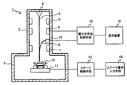
- the SEM 1 includes a lens barrel 2 having an electron optical system, a sample chamber 3, and a stage 11.
- the primary electron beam 5 generated from the electron gun 4 is irradiated to the sample 12 through the converging lens 6 and the objective lens 7, and the secondary electrons 9 generated from the sample 12 are detected by the secondary electron detector 10.
- the primary electron beam 5 scans the surface of the sample 12 observed by the scanning polarizer 8 two-dimensionally.
- the electron optical system control means 13 controls the scanning of the primary electron beam 5 by the scanning polarizer 8 and scans the intensity of the secondary electrons 9 detected by the secondary electron detector 10 in synchronization with the scanning of the primary electron beam.
- An observation image (SEM image) of the sample surface is generated by using the luminance modulation input of the generated image.
- the generated SEM image is displayed on the display device 14.
- a sample 12 to be observed is mounted on a stage 11 placed in the sample chamber 3.
- the stage 11 translates and rotationally moves the sample 12, and has a degree of freedom such as horizontal direction (XY direction), vertical direction (Z direction), rotation (rotation around the Z axis), and inclination (rotation around the X axis). have.
- the stage control means 15 controls the stage 11 in accordance with an input from a stage operation input means 16 such as a trackball or a joystick.
- a PC connected via a network or serial may be used as the stage operation input means 16.
- the rotation operation targeted by the first embodiment is performed by first setting the virtual rotation center position on the SEM image displayed on the display device 14 and inputting the rotation angle with the stage operation input means 16.
- the stage 11 includes a rotary table 210 on which a sample is directly or via a sample holder, a rotary mechanism 200 that rotates the rotary table 210, and a translation mechanism 100 that translates the rotary table 210.
- the sample is translated and rotated by moving the translation mechanism 100 and the rotation mechanism 200, and further, the sample is provided at a position different from the rotation axis of the rotary table 210 by moving the translation mechanism 100 and the rotation mechanism 200 in cooperation. Rotation operation around a virtual point, that is, rotation centric operation is realized.
- the translation mechanism 100 attaches a linear guide 102 to the base 101 and moves the movable table 103 along the linear guide 102.
- a linear motor is used as a translation mechanism driving means for driving the movable table 103.
- the linear motor shaft 104 is attached to the base, the motor main body 105 is attached to the movable table, and the movable table 103 is moved by moving the motor main body 105 along the shaft 104.
- a linear scale may be used as the translation position detecting means for detecting the position of the movable table 103.
- the linear scale 106 attached to the base 101 is provided with slits at regular intervals, and the sensor head 107 attached to the movable table 103 is moved thereon. A pulse is generated each time the sensor head 107 passes through the slit, and the position of the movable table 103 with respect to the base 101 is obtained by counting the pulses.
- the translation mechanisms may be stacked in two stages as shown in FIG.
- the rotation mechanism 200 has a rotation motor 205 attached to the uppermost movable table 103 b of the translation mechanism 100 and a rotation table 210 attached to the shaft of the rotation motor 205.
- a rotary scale 206 is used as a rotation angle detection means for detecting the rotation angle of the rotary table 210. Similar to the linear scale, the rotary scale 206 attached to the rotary table 210 is provided with slits at regular angular intervals, and the slits 210 are read by the sensor head 207 attached to the movable table 103b to thereby turn the rotary table 210 relative to the movable table 103b. Get the rotation angle of.
- stage mechanism that is a target in the first embodiment only needs to include a rotation mechanism that rotates the sample and a translation mechanism that translates the sample, and the present invention is not limited to the rotation mechanism and the translation mechanism of the first embodiment. .
- a marker for measuring the position and direction is provided on the sample, the sample holder or the rotary table, and the marker position and direction when the rotating mechanism and the translation mechanism are moved according to a predetermined pattern are measured.
- a rotation center (position) of the rotary table, a rotation error, and a correction amount for correcting the position fluctuation of the rotation center are obtained.
- the marker used in the present invention uses a characteristic figure that can be specified on the SEM image and can simultaneously measure the position and direction. For example, a triangle 400 as shown in FIG. 4 is used, and each vertex 401, 402, 403 of the triangle 400 is set as a feature point.
- a marker having a plurality of feature points at least two feature points can be used as markers.
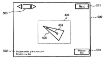
- the contour shape itself of a characteristic figure as shown in FIG. This is effective when an image processing apparatus is used, and a region 405 including a characteristic graphic 400 is selected, and edge enhancement processing is performed on the region to extract a characteristic contour shape 400.
- the center of gravity of the contour pattern 400 may be used, and the portion with the longest pattern width may be used as the marker direction.
- a contour shape such as a circle or a regular polygon
- a marker is set on a sample or the like by the method described above (step S1000).
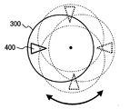
- FIG. 7 shows the marker position when rotated by 90 degrees.
- the rotation angle command value may be at least three, and does not need to be strictly in steps of a constant angle.
- a rotation angle correction amount for correcting the rotation error of the rotary table is obtained (S1003).
- ⁇ offset is an offset value of the marker direction with respect to the rotation angle of the rotary table.
- the rotation error can be corrected using this ⁇ i, and this may be used as the rotation angle correction amount.
- S1002 and S1003 show an example of the identification / calculation method performed in the first embodiment, higher accuracy calculation may be performed by combining the position and direction of the marker.
- the rotation mechanism 200 and the translation mechanism 100 are moved so that the marker is the center, and the position change amount of the marker, preferably the position and direction, is measured (S1004).
- the rotation angle is ⁇ ri simply by moving only the rotation mechanism
- the ideal position coordinates of the marker are as follows. (Xc + Rcos ( ⁇ ri + ⁇ 0), Yc + Rsin ( ⁇ ri + ⁇ 0))
- ⁇ 0 is the angle of the marker initial position from the rotary table angle origin. Therefore, if the translation mechanism is moved by the change in the marker position when the rotation mechanism is rotated, rotation with the marker as a virtual center can be realized (this is because the geometrical relationship corrects the rotation center position). This process is called geometric rotation correction).
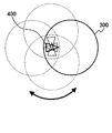
- FIG. 8 shows the state when rotated by 90 degrees.
- a translation correction amount for correcting the position fluctuation of the rotation center is obtained (S1005).
- the position fluctuation of the rotation center can be corrected by the above geometric rotation correction, but when nonlinear fluctuation occurs.
- the marker position changes due to this measurement. Since the marker position fluctuation amount corresponds to the rotation center position fluctuation, the marker position fluctuation amount may be used as the translation correction amount.
- the translation correction amount is obtained using the marker position, but the calculation required with higher accuracy may be performed using the marker position and direction.
- the rotation angle correction amount and the translation correction amount obtained by the above measurement / calculation are stored as a correction amount table using the rotation angle as an index (S1006).
- a correction value is acquired from the correction amount table.
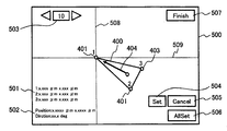
- FIGS. 9 to 11 show operation screens of SEM images on the display device 14 at the time of measurement when the marker shown in FIG. 4 has characteristic feature points of a figure.
- the translation mechanism is first moved as necessary to display the marker 400 on the SEM image 500.
- the x cursor 508 and the y cursor 509 on the screen are moved to match the position to be measured.
- the set button 504 is pressed, the position of the feature point is fixed and the coordinates are displayed in the feature point position display field 501.
- Reference numeral 505 denotes a Cancel button.
- This operation is performed for all feature points, and when completed, the AllSet button 506 is pressed. Thereby, the representative position and direction of the marker are calculated, and the result is displayed in the marker position / direction display column 502, and the vector 404 is also displayed on the SEM image.
- the measurement is continued by changing the rotation angle command value.
- the Finish button 507 is pressed, whereby the rotation center is identified and the correction amount is calculated.
- An index display 503 is provided on the SEM image 500, whereby the number of measurement points can be confirmed.
- FIG. 10 shows an example of the registration screen.
- the shape pattern 400 to be registered is displayed on the SEM image by moving the translation mechanism.
- an area 405 including a shape pattern is set using the cursor, and the PatternSet button 510 is pressed.
- image processing such as edge enhancement and binarization is performed, and the shape pattern 400 is registered as a marker.
- Reference numeral 511 denotes a Next button.
- FIG. 1 An example of the operation method when measuring the marker position and direction is shown in FIG.
- the registered shape pattern is displayed on the SEM image 500 by moving the translation mechanism as necessary.
- image processing such as edge enhancement, binarization, pattern matching is performed, the shape pattern 400 is extracted, and its representative position and direction are obtained.
- the vector 404 is also displayed on the SEM image.
- Measurement is continued by changing the rotation angle command value in the same manner as the feature point marker, and when the measurement is completed for all rotation angles, the Finish button 507 is pressed, whereby the rotation center is identified and the correction amount is calculated.
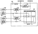
- the stage apparatus includes a translation mechanism 100, a rotation mechanism 200, and a stage control unit 300 that controls the translation mechanism 100 and the rotation mechanism 200 according to a command value given from the outside.
- the stage control means 300 includes a rotation mechanism control means 301 for controlling the rotation mechanism, a translation mechanism control means 302 for controlling the translation mechanism, and a position change of the rotation center from the geometrical point when rotating around the virtual center point. It has a geometric rotation correction means 303 for correction, and a correction amount table 304 for storing a rotation angle correction amount and a translation correction amount.
- the rotation center identification unit 305 that identifies the rotation center by performing the processing of S1002, and the correction amount table creation unit that creates the correction amount table 304 by performing S1003, S1005, and S1006 to obtain the rotation angle correction amount and the translational correction amount.
- a marker position / direction measuring means 307 is provided. These may be provided in the stage control means 300.
- a rotation angle detecting means 208 having a rotary scale and a sensor head, and a translation position detecting means 108 having a linear scale and a sensor head are provided.
- the operation of the stage device is performed as follows. First, before the operation starts, the rotation center is identified as a parameter of the geometric rotation correction means 303, and the correction amount table 304 is created. When a rotation angle command value and a translation position command value are given from the outside, a rotation angle correction amount and a translation correction amount corresponding to the given rotation angle command value are acquired from the correction amount table 304.
- the correction amount table 304 refers to the rotation angle as an index. When the given rotation angle command value is in the middle of the preceding and following indexes, interpolation is performed to obtain the correction amount.
- the obtained rotation angle correction amount and translation correction amount are added to the given rotation angle command value and translation position correction value, and the stage is moved by controlling the rotation mechanism control means 301 and the translation mechanism control means 302 accordingly. .
- the virtual rotation center position fluctuates by the rotation error multiplied by the distance from the rotation axis to the virtual center.
- the fluctuation can be corrected by correcting the rotation angle.
- the correction amount as a table for the rotation angle, it is possible to correct non-linear fluctuations that could not be corrected as a simple deviation of the rotation center.
- Trick action can be realized.
- the translation mechanism 100 and the rotation mechanism 200 of the stage apparatus according to the first embodiment have no backlash or backlash in the actuator or the transmission mechanism. Therefore, if a piezo motor is used as a driving unit for the translation mechanism 100 and the rotation mechanism 200, backlash and backlash can be reduced. This makes it possible to reduce fluctuations that are independent of the rotation angle and non-linear fluctuations, and to realize a more accurate rotation eucentric operation.
- the stage apparatus includes a translation mechanism 100, a translation position detection means 108, a rotation mechanism 200, a rotation angle detection means 208, and a stage control means 300.
- the stage control means 300 further includes a rotation mechanism control means 301, A translation mechanism control unit 302, a geometric rotation correction unit 303, and a correction amount table 304 are provided.
- a rotation center identification unit and a correction amount table creation unit are provided inside or outside the stage control unit 300.
- the rotation angle correction amount and the translation correction amount corresponding to the rotation angle detected by the rotation angle detection unit 208 are acquired.
- interpolation is performed to acquire the correction amount.
- the acquired rotation angle correction amount and translation correction amount are subtracted from the rotation angle detected from the rotation angle detection unit 208 and the translation position detected from the translation position detection unit 108, respectively, and the values are subtracted from the rotation mechanism control unit 301 and the translation. Control is performed as a feedback amount to the mechanism control means 302.
Landscapes
- Chemical & Material Sciences (AREA)
- Analytical Chemistry (AREA)
- Container, Conveyance, Adherence, Positioning, Of Wafer (AREA)
- Control Of Position Or Direction (AREA)
- Analysing Materials By The Use Of Radiation (AREA)
Abstract
Description
本発明の実施例1において、ステージ装置を用いるSEMの構成を、図2を用いて説明する。実施例1において、SEM1は電子光学系を備えた鏡筒2、試料室3、ステージ11から構成される。電子銃4から発生した一次電子線5は収束レンズ6、対物レンズ7を通して試料12に照射され、試料12から発生した二次電子9は二次電子検出器10により検出される。一次電子線5は走査偏光器8により観察する試料12の表面を二次元状に走査する。電子光学系制御手段13は走査偏光器8による一次電子線5の走査を制御するとともに、二次電子検出器10により検出される二次電子9の強度を一次電子線の走査と同期して走査生成される画像の輝度変調入力とすることで試料表面の観察画像(SEM画像)を生成する。
実施例1のステージ装置の具体的構成の一例を、図3を用いて説明する。ステージ11は、試料を直接もしくは試料ホルダを介して搭載する回転テーブル210と、回転テーブル210を回転させる回転機構200と、回転テーブル210を並進移動させる並進機構100から構成される。
本発明では、試料、試料ホルダもしくは回転テーブルに、位置と方向を測定するためのマーカーを設け、回転機構と並進機構を所定パターンに従って動かした時のマーカー位置と方向を測定し、その測定結果から回転テーブルの回転中心(位置)および回転誤差および回転中心の位置変動を補正する補正量を求める。
実施例1では、所定のパターンに従って回転機構200および並進機構100を動かし、そのときのマーカーの位置および方向を測定して、回転テーブルの回転中心の同定および回転誤差を補正する回転角補正量、回転中心の位置変動を補正する並進補正量を求める。以下に、その導出方法を、図6~8を用いて説明する。
回転角指令値:θri(i=1、・・・、n)
マーカーの位置:(Xi、Yi)(i=1、・・・、n)
マーカーの方向:θi(i=1、・・・、n)
とする。
〔数1〕
(Xi-Xc)2+(Yi-Yc)2=R2 ・・・(1)
この関係式に対して最小二乗法を適用すれば、もっとも誤差の小さい(Xc、Yc)およびRを同定することができる。
〔数2〕
Δθi=(θi-θoffset)-θri ・・・(2)
ここで、θoffsetは回転テーブルの回転角に対するマーカーの方向のオフセット値である。このΔθiを用いて回転誤差を補正することが可能であり、これを回転角補正量として利用すればよい。
(Xc+Rcos(θri+θ0)、Yc+Rsin(θri+θ0))
ここで、θ0は回転テーブル角度原点からのマーカー初期位置の角度である。そこで、回転機構を回転させたときに上記のマーカー位置の変動分だけ並進機構を移動させればマーカーを仮想中心とした回転が実現できる(これは幾何学的な関係から回転中心位置の補正を行う処理であり、幾何学的回転補正と呼ぶ)。このときは、S1003にて求めた回転角補正と上記の幾何学的回転補正を行いながら、図8に示すように回転角をθri(i=1、・・・、n)と変えていったときのマーカーの位置と方向を測定する。図8は90度ずつ回転させたときの様子を示す。
マーカーの位置:(X2i、Y2i)(i=1、・・・、n)、
マーカーの方向:θ2i(i=1、・・・、n)
回転軸の単純な偏芯、回転軸の傾きである場合には、上記の幾何学的回転補正により回転中心の位置変動を補正することはできるが、非線形的な変動が発生している場合にはこの計測によりマーカーの位置変動が発生する。このマーカーの位置変動量が回転中心の位置変動に相当するので、マーカーの位置変動量を並進補正量とすればよい。
次に、マーカーの設定および測定方法を、図9~11を用いて説明する。図9~11は、図4に示すマーカーが特徴的な図形の特徴点を持つ場合の、測定時の表示装置14におけるSEM画像の操作画面を示す。図9において、まず必要に応じて並進機構を移動させ、マーカー400をSEM画像500に表示させる。このときは特徴点401~403を用いてマーカーの代表位置および方向を測定するので、画面上のxカーソル508およびyカーソル509を移動させて、位置を測定する特徴点に合わせる。合わせられたらSetボタン504を押すと、その特徴点の位置が確定され、特徴点位置表示欄501にその座標が表示される。505はCancellボタンである。
図10および図11を用いて、図5に示す輪郭形状パターンをマーカーとして用いる場合の補正を説明する。形状パターンを用いる際にはまずパターンの登録を行う。図10はその登録画面の例である。並進機構を動かして登録したい形状パターン400をSEM画像上に表示させる。次に、カーソルを用いて形状パターンを含む領域405を設定しPatternSetボタン510を押す。これにより、エッジ強調、2値化などの画像処理が行われ、形状パターン400がマーカーとして登録される。511はNextボタンである。
次に、図1を用いて実施例1のステージ装置の制御方法を説明する。実施例1のステージ装置は、並進機構100と、回転機構200と、外部から与えられた指令値により並進機構100および回転機構200を制御するステージ制御手段300とから構成される。
11 ステージ
12 試料
13 電子光学系制御手段
14 表示装置
15 ステージ制御手段
16 ステージ操作入力手段
100 並進機構
101 並進機構ベース
102 リニアガイド
103 並進機構可動テーブル
104 リニアモータシャフト
105 リニアモータ本体
106 リニアスケール
107 センサヘッド
108 並進位置偏出手段
200 回転機構
205 回転モータ
208 回転角検出手段
210 回転テーブル
300 ステージ制御手段
301 回転機構制御手段
302 並進機構制御手段
303 幾何学的回転補正手段
304 補正量テーブル
305 回転中心同定手段
306 補正量テーブル作成手順
400 マーカーとなる図形
401~403 特徴点
404 マーカーの代表位置・方向を示すベクトル
405 画像処理領域
500 SEM画像
Claims (12)
- 試料を直接または試料ホルダを介して載置する回転テーブルと、前記回転テーブルを回転させる回転機構と、前記回転テーブルを並進移動させる並進機構と、外部から入力された回転角指令値と並進位置指令値に従って前記回転機構と前記並進機構とを制御するステージ制御手段と、を有するステージ装置において、
前記試料もしくは前記試料ホルダもしくは前記回転テーブルに設けた位置および方向を測定可能なマーカーと、
前記回転機構と前記並進機構とを所定の動作パターンに従って動作させたときの前記マーカーの位置と方向を測定するマーカー位置方向測定手段と、
前記測定の結果から前記回転テーブルの回転中心位置を同定する回転中心同定手段と、
前記回転テーブルの回転誤差を補正する回転角補正量と前記回転テーブルの回転中心位置の位置変動を補正する並進補正量とを回転角に対する補正量として作成する補正量テーブル作成手段と、
前記回転角補正量と前記並進補正量を記録する補正量テーブルと、
前記入力された回転角指令値もしくは実回転角に対応した前記回転角補正量および前記並進補正量を前記補正量テーブルから取得し、取得したこれらの補正量を用いて前記回転機構を制御する回転機構制御手段および前記並進機構を制御する並進機構制御手段を有することを特徴とするステージ装置。 - 請求の範囲第1項に記載のステージ装置において、前記補正量テーブル作成手段は、前記回転機構のみを回転させたときの前記マーカーの位置と方向を測定し、その結果から前記回転テーブルの回転中心位置と、回転誤差を補正する前記回転角補正量とを求め、
さらに前記補正量テーブル作成手段は、得られた前記回転テーブルの回転中心位置と回転角補正量とを用いて前記マーカーを仮想回転中心位置として回転させるように前記回転機構と前記並進機構とを移動させたときの前記マーカーの位置を測定し、その結果から前記回転テーブルの回転中心位置の位置変動を補正する並進補正量を求め、求められた前記回転角補正量と前記並進補正量とから回転角に対する前記補正量テーブルを作成することを特徴とするステージ装置。 - 請求の範囲第1項または第2項に記載のステージ装置において、前記ステージ制御手段は、前記入力された回転角指令値に対応した回転角補正量と前記並進補正量を前記補正量テーブルから取得し、前記入力された回転角指令値と並進位置指令値に取得した前記回転角補正量と前記並進補正量を加算した補正指令値を求め、前記補正指令値に対して前記回転機構制御手段と前記並進機構制御手段を介して前記回転機構および前記並進機構を制御することを特徴とするステージ装置。
- 請求の範囲第1項または第2項に記載のステージ装置において、前記回転テーブルの回転角を検出する回転角検出手段と、前記回転テーブルの並進位置を検出する並進位置検出手段とを備え、前記回転角検出手段および前記並進位置検出手段から実回転角および実並進位置を検出し、前記実回転角に対応した前記回転角補正量および前記並進補正量を前記補正量テーブルから取得し、前記実回転角および前記並進位置に対して前記回転角補正量および前記並進補正量を減算して補正回転角および補正並進位置を求め、前記補正回転角および前記補正並進位置をフィードバック量として用いて前記回転機構および前記並進機構とを制御することを特徴とするステージ装置。
- 請求の範囲第1項乃至第4項のいずれかに記載のステージ装置において、前記マーカーは、SEM画像のなかで少なくとも2つの特徴点を有するパターン、もしくは対象軸が1本以下の輪郭形状を有するパターンとして判定できるマーカーを用いることを特徴とするステージ装置。
- 請求の範囲第1項乃至第5項のいずれかに記載のステージ装置において、操作者がSEM画像を見ながらマーカーを選択するマーカー選択手段を有することを特徴とするステージ装置。
- 請求の範囲第1項乃至第6項のいずれかに記載のステージ装置において、前記回転機構および前記並進機構を駆動する駆動手段としてピエゾモータを用いることを特徴とするステージ装置。
- 請求の範囲第1項乃至第7項のいずれかに記載のステージ装置は、荷電粒子線装置に使用されることを特徴とするステージ装置。
- 試料を直接または試料ホルダを介して載置する回転テーブルと、前記回転テーブルを回転させる回転機構と、前記回転テーブルを並進移動させる並進機構と、外部から入力された回転角指令値と並進位置指令値に従って前記回転機構と前記並進機構とを制御するステージ制御手段と、を有するステージ装置の制御方法において、
前記試料もしくは前記試料ホルダもしくは前記回転テーブルに位置および方向を測定可能なマーカーを設け、
前記回転機構と前記並進機構とを所定の動作パターンに従って動作させたときの前記マーカーの位置と方向を測定し、
前記測定の結果から前記回転テーブルの回転中心位置を同定し、
さらに、前記回転テーブルの回転誤差を補正するための回転角補正量と前記回転テーブルの回転中心位置の位置変動を補正するための並進補正量とを回転角に対する補正量テーブルとして作成し、
前記入力された回転角指令値もしくは実回転角に対応した前記回転角補正量および前記並進補正量を前記補正量テーブルから取得し、
取得したこれらの補正量を用いて前記回転機構および前記並進機構を制御することを特徴とするステージ装置の制御方法。 - 請求の範囲第9項に記載のステージ装置の制御方法において、前記補正量テーブルの作成は、前記回転機構のみを回転させたときの前記マーカーの位置と方向を測定し、
その結果から前記回転テーブルの回転中心位置と、前記回転テーブルの回転誤差を補正するための前記回転角補正量とを求め、
前記得られた回転テーブルの回転中心位置と回転角補正量とを用いて前記マーカーを仮想回転中心位置として回転させるように前記回転機構と前記並進機構とを移動させたときの前記マーカーの少なくとも位置を測定し、
その結果から前記回転テーブルの回転中心位置の位置変動を補正するための並進補正量を求め、
求められた前記回転角補正量と前記並進補正量とから回転角に対する前記補正量テーブルを作成することを特徴とするステージ装置の制御方法。 - 請求の範囲第9項または第10項に記載のステージ装置の制御方法において、
前記入力された回転角指令値に対応した回転角補正量と前記並進補正量を前記補正量テーブルから取得し、
前記入力された回転角指令値と並進位置指令値に取得した前記回転角補正量と前記並進補正量を加算した補正指令値を求め、
前記補正指令値に対して前記回転機構および前記並進機構を制御することを特徴とするステージ装置の制御方法。 - 請求の範囲第9項乃至第11項のいずれかに記載のステージ装置の制御方法において、
回転角検出手段および並進位置検出手段から実回転角および実並進位置を検出し、
前記実回転角に対応した前記回転角補正量および前記並進補正量を前記補正量テーブルから取得し、
前記実回転角および前記並進位置に対して前記回転角補正量および前記並進補正量を減算して補正回転角および補正並進位置を求め、
前記補正回転角および前記補正並進位置をフィードバック量として用いて前記回転機構および前記並進機構とを制御することを特徴とするステージ装置の制御方法。
Priority Applications (3)
| Application Number | Priority Date | Filing Date | Title |
|---|---|---|---|
| US14/124,722 US8907303B2 (en) | 2011-06-09 | 2012-06-06 | Stage device and control method for stage device |
| CN201280028423.3A CN103608890B (zh) | 2011-06-09 | 2012-06-06 | 台装置以及台装置的控制方法 |
| DE112012002533.4T DE112012002533T5 (de) | 2011-06-09 | 2012-06-06 | Tischbaugruppe und Steuerungsverfahren für eine Tischbaugruppe |
Applications Claiming Priority (2)
| Application Number | Priority Date | Filing Date | Title |
|---|---|---|---|
| JP2011128897A JP5788719B2 (ja) | 2011-06-09 | 2011-06-09 | ステージ装置およびステージ装置の制御方法 |
| JP2011-128897 | 2011-06-09 |
Publications (1)
| Publication Number | Publication Date |
|---|---|
| WO2012169505A1 true WO2012169505A1 (ja) | 2012-12-13 |
Family
ID=47296066
Family Applications (1)
| Application Number | Title | Priority Date | Filing Date |
|---|---|---|---|
| PCT/JP2012/064504 Ceased WO2012169505A1 (ja) | 2011-06-09 | 2012-06-06 | ステージ装置およびステージ装置の制御方法 |
Country Status (5)
| Country | Link |
|---|---|
| US (1) | US8907303B2 (ja) |
| JP (1) | JP5788719B2 (ja) |
| CN (1) | CN103608890B (ja) |
| DE (1) | DE112012002533T5 (ja) |
| WO (1) | WO2012169505A1 (ja) |
Families Citing this family (10)
| Publication number | Priority date | Publication date | Assignee | Title |
|---|---|---|---|---|
| US9281163B2 (en) * | 2014-04-14 | 2016-03-08 | Fei Company | High capacity TEM grid |
| US9727047B2 (en) * | 2014-10-14 | 2017-08-08 | Kla-Tencor Corp. | Defect detection using structural information |
| JP2016205899A (ja) | 2015-04-17 | 2016-12-08 | 株式会社ミツトヨ | 回転テーブルの制御方法及び装置 |
| JP6640497B2 (ja) * | 2015-09-01 | 2020-02-05 | 株式会社日立ハイテクサイエンス | 試料ホルダ及び試料ホルダ群 |
| CN108038871A (zh) * | 2017-12-15 | 2018-05-15 | 苏州精濑光电有限公司 | 旋转平台的旋转中心确定方法、装置、服务器和存储介质 |
| JP7170490B2 (ja) * | 2018-10-11 | 2022-11-14 | 東邦チタニウム株式会社 | 金属粉体の評価方法、および評価装置 |
| CN110176407B (zh) * | 2019-04-30 | 2024-05-24 | 上海隐冠半导体技术有限公司 | 运动装置 |
| JP7360978B2 (ja) * | 2020-03-18 | 2023-10-13 | 株式会社日立ハイテクサイエンス | 荷電粒子ビーム装置 |
| WO2022141001A1 (zh) * | 2020-12-28 | 2022-07-07 | 生物岛实验室 | 一种显微镜样品台 |
| US12298260B2 (en) * | 2021-07-08 | 2025-05-13 | Illinois Tool Works Inc. | Customizable axes of rotation for industrial radiography systems |
Citations (5)
| Publication number | Priority date | Publication date | Assignee | Title |
|---|---|---|---|---|
| JP2005100676A (ja) * | 2003-09-22 | 2005-04-14 | Jeol Ltd | 荷電粒子ビーム装置及び荷電粒子ビーム装置の制御方法 |
| WO2006082714A1 (ja) * | 2005-02-02 | 2006-08-10 | Shimadzu Corporation | 走査ビーム照射装置 |
| WO2006121108A1 (ja) * | 2005-05-12 | 2006-11-16 | Riken | 荷電粒子線装置 |
| WO2010001790A1 (ja) * | 2008-07-02 | 2010-01-07 | 株式会社 日立ハイテクノロジーズ | 荷電粒子線装置 |
| WO2010047378A1 (ja) * | 2008-10-24 | 2010-04-29 | 株式会社 日立ハイテクノロジーズ | 荷電粒子線装置 |
Family Cites Families (11)
| Publication number | Priority date | Publication date | Assignee | Title |
|---|---|---|---|---|
| JP3379637B2 (ja) * | 1998-11-10 | 2003-02-24 | 株式会社島津製作所 | 電子プローブマイクロアナライザー |
| JP2000260379A (ja) | 1999-03-10 | 2000-09-22 | Hitachi Ltd | 走査形電子顕微鏡 |
| JP3859396B2 (ja) | 1999-07-19 | 2006-12-20 | 日本電子株式会社 | 走査型荷電粒子ビーム装置における試料像観察方法及び走査型荷電粒子ビーム装置 |
| JP4186464B2 (ja) | 2000-03-13 | 2008-11-26 | 株式会社日立製作所 | 荷電粒子ビーム走査式装置 |
| JP3987267B2 (ja) | 2000-05-12 | 2007-10-03 | 株式会社日立製作所 | 荷電粒子線装置 |
| JP4993849B2 (ja) * | 2004-05-31 | 2012-08-08 | 株式会社日立ハイテクノロジーズ | 不良検査装置及び荷電粒子線装置 |
| JP4515179B2 (ja) | 2004-07-20 | 2010-07-28 | 富士フイルム株式会社 | 露光装置における回転同期振れ測定方法および補償描画方法 |
| JP4988175B2 (ja) | 2005-07-11 | 2012-08-01 | 株式会社日立ハイテクノロジーズ | 荷電粒子装置用試料台 |
| JP2008146990A (ja) | 2006-12-08 | 2008-06-26 | Hitachi High-Technologies Corp | 試料固定台、及びそれを備えた荷電粒子線装置、並びに観察/解析対象箇所特定方法 |
| JP5268324B2 (ja) * | 2007-10-29 | 2013-08-21 | 株式会社日立ハイテクノロジーズ | 荷電粒子線顕微装置及び顕微方法 |
| US8939041B2 (en) * | 2011-02-10 | 2015-01-27 | Hysitron, Inc. | Nanomechanical testing system |
-
2011
- 2011-06-09 JP JP2011128897A patent/JP5788719B2/ja not_active Expired - Fee Related
-
2012
- 2012-06-06 DE DE112012002533.4T patent/DE112012002533T5/de not_active Ceased
- 2012-06-06 US US14/124,722 patent/US8907303B2/en not_active Expired - Fee Related
- 2012-06-06 CN CN201280028423.3A patent/CN103608890B/zh not_active Expired - Fee Related
- 2012-06-06 WO PCT/JP2012/064504 patent/WO2012169505A1/ja not_active Ceased
Patent Citations (5)
| Publication number | Priority date | Publication date | Assignee | Title |
|---|---|---|---|---|
| JP2005100676A (ja) * | 2003-09-22 | 2005-04-14 | Jeol Ltd | 荷電粒子ビーム装置及び荷電粒子ビーム装置の制御方法 |
| WO2006082714A1 (ja) * | 2005-02-02 | 2006-08-10 | Shimadzu Corporation | 走査ビーム照射装置 |
| WO2006121108A1 (ja) * | 2005-05-12 | 2006-11-16 | Riken | 荷電粒子線装置 |
| WO2010001790A1 (ja) * | 2008-07-02 | 2010-01-07 | 株式会社 日立ハイテクノロジーズ | 荷電粒子線装置 |
| WO2010047378A1 (ja) * | 2008-10-24 | 2010-04-29 | 株式会社 日立ハイテクノロジーズ | 荷電粒子線装置 |
Also Published As
| Publication number | Publication date |
|---|---|
| CN103608890B (zh) | 2015-01-28 |
| CN103608890A (zh) | 2014-02-26 |
| DE112012002533T5 (de) | 2014-02-27 |
| JP2012256516A (ja) | 2012-12-27 |
| US8907303B2 (en) | 2014-12-09 |
| US20140117251A1 (en) | 2014-05-01 |
| JP5788719B2 (ja) | 2015-10-07 |
Similar Documents
| Publication | Publication Date | Title |
|---|---|---|
| JP5788719B2 (ja) | ステージ装置およびステージ装置の制御方法 | |
| CN102246258B (zh) | 用于局部区域导航的高精确度射束放置 | |
| US9129773B2 (en) | Charged particle beam apparatus | |
| JP7110383B2 (ja) | アライメントシステム及び位置合わせ用シール | |
| JP4413746B2 (ja) | 荷電粒子ビーム装置 | |
| WO2010097860A1 (ja) | 荷電粒子ビーム装置、及び荷電粒子ビームにおける位置補正処理方法 | |
| JP5296578B2 (ja) | 電子顕微鏡の自動試料傾斜装置 | |
| JP5205306B2 (ja) | 走査型電子顕微鏡 | |
| US9558911B2 (en) | Method for analyzing and/or processing an object as well as a particle beam device for carrying out the method | |
| CN102820238B (zh) | 用于局部区域导航的高精确度射束放置 | |
| JP5981744B2 (ja) | 試料観察方法、試料作製方法及び荷電粒子ビーム装置 | |
| JP2005005125A (ja) | 荷電粒子線装置 | |
| JP4928987B2 (ja) | 荷電粒子線調整方法及び荷電粒子線装置 | |
| WO2006082714A1 (ja) | 走査ビーム照射装置 | |
| US10276341B2 (en) | Control method and control program for focused ion beam device | |
| CN113496859A (zh) | 带电粒子束装置 | |
| US8912487B2 (en) | Charged particle beam device, position specification method used for charged particle beam device, and program | |
| JPWO2016157403A1 (ja) | 荷電粒子線装置、荷電粒子線装置のアライメント方法、アライメントプログラム、及び記憶媒体 | |
| KR20150095203A (ko) | 하전 입자 빔 장치 | |
| JP5703404B2 (ja) | 荷電粒子線装置及び荷電粒子線を用いた測長方法 | |
| JP6101562B2 (ja) | 集束イオンビーム装置、集束イオンビーム装置を用いた試料加工方法、及び試料加工プログラム | |
| KR102843051B1 (ko) | 집속 이온 빔 장치 | |
| JPH09283073A (ja) | イオンビーム照射装置 | |
| US11079584B2 (en) | Method for use in optical imaging, a system for using in optical imaging and an optical system | |
| JP3870141B2 (ja) | 電子顕微鏡 |
Legal Events
| Date | Code | Title | Description |
|---|---|---|---|
| 121 | Ep: the epo has been informed by wipo that ep was designated in this application |
Ref document number: 12796210 Country of ref document: EP Kind code of ref document: A1 |
|
| WWE | Wipo information: entry into national phase |
Ref document number: 14124722 Country of ref document: US |
|
| NENP | Non-entry into the national phase |
Ref country code: DE |
|
| WWE | Wipo information: entry into national phase |
Ref document number: 1120120025334 Country of ref document: DE Ref document number: 112012002533 Country of ref document: DE |
|
| 122 | Ep: pct application non-entry in european phase |
Ref document number: 12796210 Country of ref document: EP Kind code of ref document: A1 |