WO2012165634A1 - インサート成形用金型及びカラーのインサート成形方法 - Google Patents
インサート成形用金型及びカラーのインサート成形方法 Download PDFInfo
- Publication number
- WO2012165634A1 WO2012165634A1 PCT/JP2012/064329 JP2012064329W WO2012165634A1 WO 2012165634 A1 WO2012165634 A1 WO 2012165634A1 JP 2012064329 W JP2012064329 W JP 2012064329W WO 2012165634 A1 WO2012165634 A1 WO 2012165634A1
- Authority
- WO
- WIPO (PCT)
- Prior art keywords
- collar
- mold
- insert
- collars
- insert molding
- Prior art date
- Legal status (The legal status is an assumption and is not a legal conclusion. Google has not performed a legal analysis and makes no representation as to the accuracy of the status listed.)
- Ceased
Links
Images




Classifications
-
- B—PERFORMING OPERATIONS; TRANSPORTING
- B29—WORKING OF PLASTICS; WORKING OF SUBSTANCES IN A PLASTIC STATE IN GENERAL
- B29C—SHAPING OR JOINING OF PLASTICS; SHAPING OF MATERIAL IN A PLASTIC STATE, NOT OTHERWISE PROVIDED FOR; AFTER-TREATMENT OF THE SHAPED PRODUCTS, e.g. REPAIRING
- B29C45/00—Injection moulding, i.e. forcing the required volume of moulding material through a nozzle into a closed mould; Apparatus therefor
- B29C45/14—Injection moulding, i.e. forcing the required volume of moulding material through a nozzle into a closed mould; Apparatus therefor incorporating preformed parts or layers, e.g. injection moulding around inserts or for coating articles
- B29C45/14008—Inserting articles into the mould
-
- B—PERFORMING OPERATIONS; TRANSPORTING
- B29—WORKING OF PLASTICS; WORKING OF SUBSTANCES IN A PLASTIC STATE IN GENERAL
- B29C—SHAPING OR JOINING OF PLASTICS; SHAPING OF MATERIAL IN A PLASTIC STATE, NOT OTHERWISE PROVIDED FOR; AFTER-TREATMENT OF THE SHAPED PRODUCTS, e.g. REPAIRING
- B29C45/00—Injection moulding, i.e. forcing the required volume of moulding material through a nozzle into a closed mould; Apparatus therefor
- B29C45/14—Injection moulding, i.e. forcing the required volume of moulding material through a nozzle into a closed mould; Apparatus therefor incorporating preformed parts or layers, e.g. injection moulding around inserts or for coating articles
- B29C45/14065—Positioning or centering articles in the mould
-
- B—PERFORMING OPERATIONS; TRANSPORTING
- B29—WORKING OF PLASTICS; WORKING OF SUBSTANCES IN A PLASTIC STATE IN GENERAL
- B29C—SHAPING OR JOINING OF PLASTICS; SHAPING OF MATERIAL IN A PLASTIC STATE, NOT OTHERWISE PROVIDED FOR; AFTER-TREATMENT OF THE SHAPED PRODUCTS, e.g. REPAIRING
- B29C45/00—Injection moulding, i.e. forcing the required volume of moulding material through a nozzle into a closed mould; Apparatus therefor
- B29C45/14—Injection moulding, i.e. forcing the required volume of moulding material through a nozzle into a closed mould; Apparatus therefor incorporating preformed parts or layers, e.g. injection moulding around inserts or for coating articles
- B29C45/14065—Positioning or centering articles in the mould
- B29C2045/14147—Positioning or centering articles in the mould using pins or needles penetrating through the insert
-
- B—PERFORMING OPERATIONS; TRANSPORTING
- B29—WORKING OF PLASTICS; WORKING OF SUBSTANCES IN A PLASTIC STATE IN GENERAL
- B29C—SHAPING OR JOINING OF PLASTICS; SHAPING OF MATERIAL IN A PLASTIC STATE, NOT OTHERWISE PROVIDED FOR; AFTER-TREATMENT OF THE SHAPED PRODUCTS, e.g. REPAIRING
- B29C45/00—Injection moulding, i.e. forcing the required volume of moulding material through a nozzle into a closed mould; Apparatus therefor
- B29C45/14—Injection moulding, i.e. forcing the required volume of moulding material through a nozzle into a closed mould; Apparatus therefor incorporating preformed parts or layers, e.g. injection moulding around inserts or for coating articles
- B29C45/14065—Positioning or centering articles in the mould
- B29C2045/14163—Positioning or centering articles in the mould using springs being part of the positioning means
Definitions
- the present invention relates to an insert molding die and a collar insert molding method, and in particular, to a mold used when molding a resin product in which a collar is insert-molded on an inner peripheral surface of a bolt insertion hole, and the die.
- the present invention relates to an insert molding method for the collar used.
- Patent Document 1 By inserting the screw part of the bolt into this collar and tightening the bolt, the bottom surface of the head of the bolt comes into contact with the collar and the bolt tightening force can be received by the collar, and the resin product can be prevented from being damaged.
- Patent Document 1 when molding a resin product in which a collar is insert-molded on the inner peripheral surface of a bolt insertion hole, the collar is positioned in a cavity formed by a pair of molds, and a molten resin is placed in the cavity.
- the resin is molded by wrapping the collar with molten resin and solidifying the resin.
- colors having different heights may be used for the same resin product, and it is not preferable from the viewpoint of work efficiency and cost to replace the mold in accordance with the color height.
- the height of the collar is larger than the mold dimension in the thickness direction of the resin product. If it is small, the collar is buried in the resin product, and the tightening force of the bolt cannot be directly received by the collar, and the resin product may be damaged. On the other hand, if the height of the collar is larger than the mold dimension in the thickness direction of the resin product, the collar may be sandwiched between the pair of molds with a strong pressure during insert molding, and the mold or the collar may be damaged.
- the problem to be solved by the present invention is to realize a mold for insert molding that can cope with different colors in molds used for insert molding of collars and can absorb manufacturing tolerances. There is to molding.
- an insert molding die and a collar insert molding method having the following configuration.
- a nesting insertion hole to be slidably inserted is formed, and a cavity surrounding the collar is formed in the other mold, and the nesting is an upper portion of a cross-sectional shape corresponding to the internal cross-sectional shape of the collar
- a mold having a cross-sectional shape corresponding to the outer cross-sectional shape of the collar and elastically biased toward the other mold.
- the elastically biased insert inserted into the insert insertion hole of one mold is inserted into the collar. Then, the collar is positioned in the cavity by clamping the other mold. At this time, since only an elastic urging force is applied between the collar and the mold, damage to the collar and the mold can be prevented. For example, even if the collar is made higher (longer) than the length of the bolt insertion hole of the resin product, damage to the collar or mold can be suppressed, so the end face of the collar can be protruded from the resin product and brought into contact with the bolt The bolt tightening force can be reliably received with the collar.
- the collar is positioned by the elastic biasing force, it is possible to absorb the difference in height of the collar due to manufacturing tolerances and the like.
- the elastic biasing force applied to the nest is set to such a size that the nest does not retract due to the injection pressure of the molten resin injected into the cavity. Further, since the collar and the mold are damaged when the elastic biasing force is too large, the elastic biasing force is set to a size that does not damage the collar and the mold.
- the collar is attached to the top of the mold, and the other mold is pressed against the one mold in a state where the insert is elastically biased toward the other mold, and the mold is melted in the cavity.
- Color insert molding method in which resin is injected and molded.
- FIG. 1 is a perspective view of an insert mold according to an embodiment of the present invention and a resin product molded with the mold.
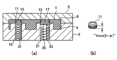
- 2A is a cross-sectional view of a mold in which resin is injected after being clamped, cut along the line QQ in FIG. 1, and FIG. 2B shows the height of the hollow cylindrical collar.
- FIG. 3A is a perspective view of the resin product of FIG. 1 viewed from a movable mold
- FIG. 3B is a perspective view of the resin product of FIG. 1 viewed from a fixed mold.
- FIG. 3C is a perspective view of a hollow cylindrical shape and a hollow elliptical cylindrical color.
- FIG. 4A is a perspective view of a hollow cylindrical collar and a nest, and FIG.
- FIG. 4B is a perspective view of a state in which the nest is inserted into the hollow cylindrical collar.
- FIG. 5A is a perspective view of a hollow oval cylindrical collar and a nest
- FIG. 5B is a perspective view of a state where the nest is inserted into the hollow oval cylindrical collar.
- FIG. 6 is a perspective view of a fixed-side mold in a state where a nest is inserted into a hollow cylindrical shape and a hollow elliptical cylindrical shape.
- FIG. 7A is a cross-sectional view in the case of using a hollow cylindrical collar and a hollow elliptical cylindrical collar having a small height in the cross-sectional view of FIG. 2A
- FIG. 7B is a hollow cylindrical collar. It is a figure which shows the height of.
- FIG. 7A is a cross-sectional view in the case of using a hollow cylindrical collar and a hollow elliptical cylindrical collar having a small height in the cross-sectional view of FIG. 2A
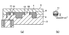
- FIG. 8A is a cross-sectional view when a hollow cylindrical collar and a hollow elliptical cylindrical collar having a large height are used in the cross-sectional view of FIG. 2A
- FIG. 8B is a hollow cylindrical collar. It is a figure which shows the height of.
- FIG. 9A is a cross-sectional view when the insert is fixed to a mold as a comparative example in the cross-sectional view of FIG. 2A
- FIG. 9B is a view showing the height of the hollow cylindrical collar. is there.
- FIG. 10A is a cross-sectional view when the insert is fixed to a mold as a comparative example in the cross-sectional view of FIG. 2A
- FIG. 10B is a view showing the height of the hollow cylindrical collar. is there.
- the insert mold according to this embodiment includes a pair of molds 3 and 5 for molding the resin product 1.
- the resin product 1 has bolt insertion holes 7 and 9 into which bolts (not shown) are inserted when the resin product 1 is fixed to an attachment target. Is provided.
- the bolt insertion hole 7 is formed in a circular shape
- the bolt insertion hole 9 is formed in an elliptical shape.
- Metal collars 11 and 13 are insert-molded on the inner peripheral surfaces of the bolt insertion holes 7 and 9. The collars 11 and 13 are formed in accordance with the internal cross-sectional shape of the bolt insertion holes 7 and 9.
- the collar 11 insert-molded in the circular bolt insertion hole 7 is formed in a hollow cylindrical shape
- the collar 13 insert-molded in the elliptical bolt insertion hole 9 is formed in a hollow elliptic cylinder.
- the outer peripheral surface of the collar 11 is formed with uneven portions 12 in which a plurality of uneven portions are alternately formed.
- a plurality of convex portions 14 are formed on the outer peripheral surface of the collar 13.
- the resin 11 is configured so that the collars 11 and 13 do not fall off from the resin product 1 by hardening the resin along the shapes of the concavo-convex portions 12 and the convex portions 14.
- the pair of molds 3 and 5 is constituted by a mold 3 which is a fixed side and a mold 5 which is a movable side, and is clamped by a molding machine (not shown). Clamped with force.
- the molds 3 and 5 are respectively formed with cavities 4 and 6 into which molten resin is injected, and the mold 5 placed opposite to the fixed mold 3 is pressed and clamped to mold the resin product 1.
- the cavities 4 and 6 corresponding to the shape of are formed.
- One of the molds 3 and 5 is provided with a gate (not shown) for injecting molten resin into the cavities 4 and 6.
- Nest insertion holes 19 and 21 into which the inserts 15 and 17 are slidably inserted are formed in the mold 3 on the fixed side.
- the inserts 15 and 17 are formed with upper portions 23 and 25 inserted into the collars 11 and 13, respectively, and bottom portions 27 and 29 that receive the collars 11 and 13 inserted in connection with the upper portions 23 and 25.
- the upper portion 23 of the insert 15 is formed in a columnar shape corresponding to the internal cross-sectional shape of the hollow cylindrical collar 11, and the bottom portion 27 is formed outside the hollow cylindrical collar 11. It is formed in a disk shape corresponding to the normal cross-sectional shape. As shown in FIG.
- the upper portion 25 of the insert 17 is formed in an elliptical column shape corresponding to the internal cross-sectional shape of the hollow elliptical cylindrical collar 13, and the bottom portion 29 is formed in the hollow elliptical cylindrical collar 13. It is formed in an elliptical disk shape corresponding to the outer cross-sectional shape.
- the nesting insertion hole 19 is formed in such a size that the inner peripheral surface is in sliding contact with the outer peripheral surface of the bottom portion 27 of the nesting 15.
- the nesting insertion hole 21 is formed in such a size that the inner peripheral surface is in sliding contact with the outer peripheral surface of the bottom 29 of the nesting 17.
- the spring members 31 and 33 are supported by a driving device (not shown) so as to advance and retract in the nesting insertion holes 19 and 21.
- One end of each spring member 31, 33 is supported by the drive device, and the other end is configured to be connected or abutted to the bottom portions 27, 29 of each insert 15, 17.
- one end of the spring member 31 inserted into the insert insertion hole 19 is connected to the drive device, and the other end is connected to the bottom 27 of the insert 15.
- a rod 35 erected on the drive device is inserted into the spring member 33 inserted into the insert insertion hole 21, one end of the spring member 33 abuts the drive device, and the other end contacts the bottom 29 of the insert 17. It is comprised so that it may contact
- FIG. 1 The effect
- FIG. 1 The inserts 15 and 17 are inserted into the insert insertion holes 19 and 21 of the mold 3, and the spring members 31 and 33 are inserted into the insert insertion holes 19 and 21 so as to contact the bottoms 27 and 29 of the inserts. .
- the upper portions 23, 25 of the inserts 15, 17 protrude from the insert insertion holes 19, 21 and are inserted so as to be elastically urged by the spring members 31, 33.
- the protruding upper portions 23 and 25 are inserted into the hollow portions of the collars 11 and 13, and one end surfaces of the collars 11 and 13 are brought into contact with the upper surfaces of the bottom portions 27 and 29.
- the collars 11 and 13 are attached to the upper portions 23 and 25 of the nestings 15 and 17, respectively.
- the cavities 4 and 6 of the resin product 1 surrounding the collars 11 and 13 are formed by closing the mold 3 and the mold 5 with a set clamping force by the molding machine.
- the respective collars 11, 13 are elastically biased by the respective spring members 31, 33, the other end surfaces of the respective collars 11, 13 abut against the mold 5, and are positioned in the cavities 4, 6. Is retained.
- the collars 11 and 13 when insert molding is performed, the collars 11 and 13 are positioned between the mold 5 and the inserts 15 and 17 by the elastic biasing force of the spring members 31 and 33. That is, since each collar 11 and 13 is only applied with an elastic urging force smaller than the clamping force, the collars 11 and 13 can be prevented from being damaged by clamping the molds 3 and 5. Thereby, the collars 11 and 13 whose height is larger than the thickness of the resin product 1 can be used, and the end surfaces of the collars 11 and 13 can be reliably exposed on the surface of the resin product 1. Therefore, the fastening force of the bolt when the resin product 1 is attached to the attachment object can be directly received by each of the collars 11 and 13.
- the spring members 31 and 33 can be expanded and contracted according to the height of the collars 11 and 13 to position the collars 11 and 13, it is possible to use a collar that varies in height due to manufacturing errors.
- this invention is not limited to embodiment mentioned above, A deformation
- the material, shape, dimensions, number, arrangement location, and the like of each component in the above-described embodiment are arbitrary and are not limited as long as the present invention can be achieved.
- This application is based on a Japanese patent application (Japanese Patent Application No. 2011-124217) filed on June 2, 2011, the contents of which are incorporated herein by reference.
- the insert molding die based on the present invention it is possible to realize a die that can cope with colors having different heights and absorb manufacturing tolerances, and can insert the collar.
Landscapes
- Engineering & Computer Science (AREA)
- Manufacturing & Machinery (AREA)
- Mechanical Engineering (AREA)
- Moulds For Moulding Plastics Or The Like (AREA)
- Injection Moulding Of Plastics Or The Like (AREA)
Abstract
Description
(1)ボルト挿入穴の内周面にカラーがインサート成形される樹脂製品を成形する一対の金型と、前記カラーに挿入される入れ子とを備え、一方の前記金型には、前記入れ子が摺動可能に挿入される入れ子挿入穴が形成され、他方の前記金型には、前記カラーを包囲するキャビティが形成され、前記入れ子が、前記カラーの内法断面形状に対応する断面形状の上部と、前記カラーの外法断面形状に対応する断面形状の底部とを備え、前記他方の金型に向けて弾性付勢されるインサート成形用金型。
以下、本発明を実施の形態に基づいて説明する。
図1~6に示すとおり、本実施形態のインサート成形用金型は、樹脂製品1を成形する一対の金型3、5を備えている。
図3(a)及び図3(b)に示すように、樹脂製品1には、取付対象物に樹脂製品1を固定する際、図示していないボルトが挿入されるボルト挿入穴7、9が設けられている。ボルト挿入穴7は円形に形成され、ボルト挿入穴9は楕円形に形成されている。ボルト挿入穴7、9の内周面には、金属製のカラー11、13がインサート成形されている。各カラー11、13は、ボルト挿入穴7、9の内法断面形状に合わせて形成されている。つまり、円形のボルト挿入穴7にインサート成形されるカラー11は中空円筒形に形成され、楕円形のボルト挿入穴9にインサート成形されるカラー13は中空楕円筒形に形成されている。
図4(a)に示すように、カラー11の外周面には、複数の凹凸が交互に形成された凹凸部12が形成されている。図5(a)に示すように、カラー13の外周面には、複数の凸部14が形成されている。凹凸部12と凸部14の形状に沿って樹脂を固めることで、樹脂製品1からカラー11、13が脱落しないように構成されている。
金型3の各入れ子挿入穴19、21にそれぞれ入れ子15、17を挿入し、各入れ子の底部27、29に当接するように各入れ子挿入穴19、21に各ばね部材31、33を挿入する。この際、各入れ子15、17の各上部23、25が各入れ子挿入穴19、21から突出し、各ばね部材31、33によって弾性付勢されるように挿入する。この突出した各上部23、25を各カラー11、13の中空部に挿入し、各カラー11、13の一端面を各底部27、29の上面に当接させる。これにより、各入れ子15、17の各上部23、25に各カラー11、13が装着される。この状態で、成形機によって金型3と金型5を設定した型締め力で閉じることで、各カラー11、13を包囲する樹脂製品1のキャビティ4、6が形成される。この際、各ばね部材31、33によって各カラー11、13が弾性付勢され、各カラー11、13の他端面が金型5に当接して位置決めされキャビティ4、6内に各カラー11、13が保持される。
すなわち、本実施形態のインサート成形用金型は、金型3の各入れ子挿入穴19、21に摺動可能に挿入されて弾性付勢された各入れ子15、17によって各カラー11、13を位置決めするので、各カラー11、13の位置における樹脂製品1の厚さ方向の金型寸法を、各カラー11、13の高さに一致させることができる。
また、本出願は、2011年6月2日出願の日本特許出願(特願2011-124217)に基づくものであり、その内容はここに参照として取り込まれる。
3、5 金型
4、6 キャビティ
7、9 ボルト挿入穴
11、13 カラー
15、17 入れ子
19、21 入れ子挿入穴
23、25 上部
27、29 底部
31、33 ばね部材
Claims (3)
- ボルト挿入穴の内周面にカラーがインサート成形される樹脂製品を成形する一対の金型と、前記カラーに挿入される入れ子とを備え、
一方の前記金型には、前記入れ子が摺動可能に挿入される入れ子挿入穴が形成され、他方の前記金型には、前記カラーを包囲するキャビティが形成され、
前記入れ子が、前記カラーの内法断面形状に対応する断面形状の上部と、前記カラーの外法断面形状に対応する断面形状の底部とを備え、前記他方の金型に向けて弾性付勢されるインサート成形用金型。 - 請求項1に記載のインサート成形用金型であって、
前記入れ子が、前記入れ子挿入穴に挿入されるばね部材によって弾性付勢されるインサート成形用金型。 - 請求項1又は2に記載のインサート成形用金型を用いたカラーのインサート成形方法であって、
前記一方の金型の前記入れ子挿入穴に前記入れ子を挿入し、前記入れ子の上部に前記カラーを装着し、前記入れ子を前記他方の金型に向けて弾性付勢した状態で前記他方の金型を前記一方の金型に押圧して型締めし、前記キャビティ内に溶融樹脂を注入して成形するカラーのインサート成形方法。
Priority Applications (4)
| Application Number | Priority Date | Filing Date | Title |
|---|---|---|---|
| DE112012002306.4T DE112012002306T5 (de) | 2011-06-02 | 2012-06-01 | Formwerkzeug zum Einsatz-Spritzguß und Verfahren zum Einsatz-Spritzguß für einen Kragen |
| KR1020137031363A KR101553133B1 (ko) | 2011-06-02 | 2012-06-01 | 인서트 성형용 금형 및 칼라의 인서트 성형방법 |
| CN201280025641.1A CN103561926B (zh) | 2011-06-02 | 2012-06-01 | 用于嵌入模制的模具及用于嵌入模制套圈的方法 |
| US14/084,808 US20140070454A1 (en) | 2011-06-02 | 2013-11-20 | Die for insert molding and method for insert molding of collar |
Applications Claiming Priority (2)
| Application Number | Priority Date | Filing Date | Title |
|---|---|---|---|
| JP2011124217A JP5770537B2 (ja) | 2011-06-02 | 2011-06-02 | インサート成形用金型及びカラーのインサート成形方法 |
| JP2011-124217 | 2011-06-02 |
Related Child Applications (1)
| Application Number | Title | Priority Date | Filing Date |
|---|---|---|---|
| US14/084,808 Continuation US20140070454A1 (en) | 2011-06-02 | 2013-11-20 | Die for insert molding and method for insert molding of collar |
Publications (1)
| Publication Number | Publication Date |
|---|---|
| WO2012165634A1 true WO2012165634A1 (ja) | 2012-12-06 |
Family
ID=47259482
Family Applications (1)
| Application Number | Title | Priority Date | Filing Date |
|---|---|---|---|
| PCT/JP2012/064329 Ceased WO2012165634A1 (ja) | 2011-06-02 | 2012-06-01 | インサート成形用金型及びカラーのインサート成形方法 |
Country Status (6)
| Country | Link |
|---|---|
| US (1) | US20140070454A1 (ja) |
| JP (1) | JP5770537B2 (ja) |
| KR (1) | KR101553133B1 (ja) |
| CN (1) | CN103561926B (ja) |
| DE (1) | DE112012002306T5 (ja) |
| WO (1) | WO2012165634A1 (ja) |
Cited By (1)
| Publication number | Priority date | Publication date | Assignee | Title |
|---|---|---|---|---|
| CN114889039A (zh) * | 2022-04-19 | 2022-08-12 | 微智医疗器械有限公司 | 视网膜植入体柔性电极及其包胶模具、包胶方法 |
Families Citing this family (15)
| Publication number | Priority date | Publication date | Assignee | Title |
|---|---|---|---|---|
| JP5661087B2 (ja) * | 2012-11-30 | 2015-01-28 | 東海興業株式会社 | インサート成形品、インサート成形方法、及びインサート成形装置 |
| JP2015185835A (ja) * | 2014-03-26 | 2015-10-22 | 株式会社デンソー | 半導体装置及びその製造方法 |
| JP6891048B2 (ja) * | 2017-06-02 | 2021-06-18 | アピックヤマダ株式会社 | 樹脂モールド金型及び樹脂モールド装置 |
| DE102018102947A1 (de) * | 2018-02-09 | 2019-08-14 | Bbg Gmbh & Co. Kg | Vorrichtung zum Umspritzen oder Umschäumen deckelförmiger Bauteile |
| CN110576560A (zh) * | 2018-06-08 | 2019-12-17 | 汉达精密电子(昆山)有限公司 | 多孔定位结构 |
| JP7067390B2 (ja) * | 2018-09-26 | 2022-05-16 | 住友電装株式会社 | インサート成形品の製造方法 |
| KR102189531B1 (ko) * | 2019-08-29 | 2020-12-11 | 박순곤 | 플랜지 일체형 리니어 베어링용 인서트 사출 금형 |
| EP4122670A1 (de) * | 2021-07-23 | 2023-01-25 | Weißer und Grießhaber Gesellschaft mit beschränkter Haftung | Verfahren zur herstellung einer kunststoffabdeckung mit einer elektrischen leiterbahn |
| DE102021122614A1 (de) | 2021-09-01 | 2023-03-02 | Reichenbacher Hamuel Gmbh | Verfahren zur Herstellung von Formteilen und Anlage zur Durchführung des Verfahrens |
| DE102022119114A1 (de) | 2022-07-29 | 2024-02-01 | Knaus Tabbert Ag | Dämmelement sowie System und Verfahren zur Herstellung eines solchen |
| KR102823552B1 (ko) | 2022-11-22 | 2025-06-20 | 주식회사 코넥 | 금형 내 인서트 고정 장치 |
| CN115742189B (zh) * | 2022-12-02 | 2025-11-04 | 南昌大学 | 一种回转类嵌件的嵌件成型装置 |
| DE102022132817A1 (de) * | 2022-12-09 | 2024-06-20 | HELLA GmbH & Co. KGaA | Spritzgießwerkzeug zum Herstellen eines Spritzgussbauteils sowie Verfahren zum Herstellen eines Spritzgussbauteils |
| DE102023205835A1 (de) * | 2023-06-21 | 2024-12-24 | Magna powertrain gmbh & co kg | Spritzgießwerkzeug zum Beschichten einer Komponente und Verfahren zum Beschichten einer Komponente unter Verwendung eines solchen Werkzeugs |
| CN120716100B (zh) * | 2025-08-21 | 2025-11-04 | 皇裕精密技术(苏州)股份有限公司 | 低成本改善衬套公差的镶件结构及模具 |
Citations (3)
| Publication number | Priority date | Publication date | Assignee | Title |
|---|---|---|---|---|
| JPH0265527U (ja) * | 1988-11-09 | 1990-05-17 | ||
| JPH0282510U (ja) * | 1988-12-13 | 1990-06-26 | ||
| JP2004042561A (ja) * | 2002-07-15 | 2004-02-12 | Sumitomo Wiring Syst Ltd | インサート成形品及びその製造方法 |
Family Cites Families (5)
| Publication number | Priority date | Publication date | Assignee | Title |
|---|---|---|---|---|
| JPS5219499B2 (ja) * | 1972-12-13 | 1977-05-28 | ||
| JPS6049403B2 (ja) * | 1980-04-25 | 1985-11-01 | 古河電気工業株式会社 | スリ−ブの外周に樹脂層を被覆する射出成型用金型組立体 |
| JPS63116817A (ja) * | 1986-11-06 | 1988-05-21 | Copal Co Ltd | インサ−ト成形金型 |
| JP3059681B2 (ja) * | 1996-09-24 | 2000-07-04 | 正行 定塚 | トンネル用止水シートの取付構造および取付方法 |
| JP4027281B2 (ja) * | 2002-07-10 | 2007-12-26 | キヤノン株式会社 | インクジェット記録ヘッド |
-
2011
- 2011-06-02 JP JP2011124217A patent/JP5770537B2/ja active Active
-
2012
- 2012-06-01 WO PCT/JP2012/064329 patent/WO2012165634A1/ja not_active Ceased
- 2012-06-01 DE DE112012002306.4T patent/DE112012002306T5/de active Pending
- 2012-06-01 CN CN201280025641.1A patent/CN103561926B/zh active Active
- 2012-06-01 KR KR1020137031363A patent/KR101553133B1/ko active Active
-
2013
- 2013-11-20 US US14/084,808 patent/US20140070454A1/en not_active Abandoned
Patent Citations (3)
| Publication number | Priority date | Publication date | Assignee | Title |
|---|---|---|---|---|
| JPH0265527U (ja) * | 1988-11-09 | 1990-05-17 | ||
| JPH0282510U (ja) * | 1988-12-13 | 1990-06-26 | ||
| JP2004042561A (ja) * | 2002-07-15 | 2004-02-12 | Sumitomo Wiring Syst Ltd | インサート成形品及びその製造方法 |
Cited By (1)
| Publication number | Priority date | Publication date | Assignee | Title |
|---|---|---|---|---|
| CN114889039A (zh) * | 2022-04-19 | 2022-08-12 | 微智医疗器械有限公司 | 视网膜植入体柔性电极及其包胶模具、包胶方法 |
Also Published As
| Publication number | Publication date |
|---|---|
| JP2012250419A (ja) | 2012-12-20 |
| DE112012002306T5 (de) | 2014-03-27 |
| JP5770537B2 (ja) | 2015-08-26 |
| US20140070454A1 (en) | 2014-03-13 |
| KR101553133B1 (ko) | 2015-09-14 |
| CN103561926B (zh) | 2016-06-01 |
| KR20140006080A (ko) | 2014-01-15 |
| CN103561926A (zh) | 2014-02-05 |
Similar Documents
| Publication | Publication Date | Title |
|---|---|---|
| JP5770537B2 (ja) | インサート成形用金型及びカラーのインサート成形方法 | |
| US9314950B2 (en) | Fixed platen of injection molding machine | |
| JP6033955B2 (ja) | 鋳造用金型 | |
| EP2251173B1 (en) | Mold holding member and mold clamping device | |
| JP7067390B2 (ja) | インサート成形品の製造方法 | |
| EP3461612B1 (en) | Undercut processing mechanism and molding die assembly | |
| US11400629B2 (en) | Injection molding die | |
| JP2012166423A (ja) | トグルリンク式型締装置のリアプラテン | |
| JP6180260B2 (ja) | 樹脂製窓の回転2色射出成形装置 | |
| JP6137232B2 (ja) | 射出成形金型 | |
| JP2008265026A (ja) | プラスチック射出成形金型及びプラスチック成形品 | |
| JP6094799B2 (ja) | 電池及び電池の製造方法 | |
| JP5851379B2 (ja) | 射出圧縮成形用金型 | |
| JP6867920B2 (ja) | インサート成形用金型及びこれにより得られる樹脂成形品 | |
| JP2023152777A (ja) | 金型装置 | |
| JP2007083273A (ja) | 鋳造用金型装置 | |
| JP2010046880A (ja) | 筐体の製造方法及び検出装置 | |
| JP2013028036A (ja) | 射出成形方法及びその装置 | |
| KR101261580B1 (ko) | 인서트 성형용 금형 | |
| JP2005014543A (ja) | 射出成形用金型装置及びその装置を使用した射出成形品仕様変更方法 | |
| JP2010052322A (ja) | 射出成形機 | |
| JP2005246770A (ja) | 射出成形金型 | |
| WO2023218511A1 (ja) | ノイズ対策部材及びその製造方法 | |
| JP5134306B2 (ja) | 成形型装置及び高分子成形方法 | |
| JP2010125808A (ja) | キャップの射出成形方法及びキャップ |
Legal Events
| Date | Code | Title | Description |
|---|---|---|---|
| 121 | Ep: the epo has been informed by wipo that ep was designated in this application |
Ref document number: 12793041 Country of ref document: EP Kind code of ref document: A1 |
|
| ENP | Entry into the national phase |
Ref document number: 20137031363 Country of ref document: KR Kind code of ref document: A |
|
| WWE | Wipo information: entry into national phase |
Ref document number: 112012002306 Country of ref document: DE Ref document number: 1120120023064 Country of ref document: DE |
|
| 122 | Ep: pct application non-entry in european phase |
Ref document number: 12793041 Country of ref document: EP Kind code of ref document: A1 |