WO2012165622A1 - 車輌用アクセルペダル踏み圧調節システム - Google Patents
車輌用アクセルペダル踏み圧調節システム Download PDFInfo
- Publication number
- WO2012165622A1 WO2012165622A1 PCT/JP2012/064298 JP2012064298W WO2012165622A1 WO 2012165622 A1 WO2012165622 A1 WO 2012165622A1 JP 2012064298 W JP2012064298 W JP 2012064298W WO 2012165622 A1 WO2012165622 A1 WO 2012165622A1
- Authority
- WO
- WIPO (PCT)
- Prior art keywords
- pedal
- pressure
- vehicle
- accelerator pedal
- weight
- Prior art date
Links
Images


Classifications
-
- B—PERFORMING OPERATIONS; TRANSPORTING
- B60—VEHICLES IN GENERAL
- B60L—PROPULSION OF ELECTRICALLY-PROPELLED VEHICLES; SUPPLYING ELECTRIC POWER FOR AUXILIARY EQUIPMENT OF ELECTRICALLY-PROPELLED VEHICLES; ELECTRODYNAMIC BRAKE SYSTEMS FOR VEHICLES IN GENERAL; MAGNETIC SUSPENSION OR LEVITATION FOR VEHICLES; MONITORING OPERATING VARIABLES OF ELECTRICALLY-PROPELLED VEHICLES; ELECTRIC SAFETY DEVICES FOR ELECTRICALLY-PROPELLED VEHICLES
- B60L15/00—Methods, circuits, or devices for controlling the traction-motor speed of electrically-propelled vehicles
- B60L15/10—Methods, circuits, or devices for controlling the traction-motor speed of electrically-propelled vehicles for automatic control superimposed on human control to limit the acceleration of the vehicle, e.g. to prevent excessive motor current
-
- B—PERFORMING OPERATIONS; TRANSPORTING
- B60—VEHICLES IN GENERAL
- B60L—PROPULSION OF ELECTRICALLY-PROPELLED VEHICLES; SUPPLYING ELECTRIC POWER FOR AUXILIARY EQUIPMENT OF ELECTRICALLY-PROPELLED VEHICLES; ELECTRODYNAMIC BRAKE SYSTEMS FOR VEHICLES IN GENERAL; MAGNETIC SUSPENSION OR LEVITATION FOR VEHICLES; MONITORING OPERATING VARIABLES OF ELECTRICALLY-PROPELLED VEHICLES; ELECTRIC SAFETY DEVICES FOR ELECTRICALLY-PROPELLED VEHICLES
- B60L15/00—Methods, circuits, or devices for controlling the traction-motor speed of electrically-propelled vehicles
- B60L15/20—Methods, circuits, or devices for controlling the traction-motor speed of electrically-propelled vehicles for control of the vehicle or its driving motor to achieve a desired performance, e.g. speed, torque, programmed variation of speed
-
- B—PERFORMING OPERATIONS; TRANSPORTING
- B60—VEHICLES IN GENERAL
- B60L—PROPULSION OF ELECTRICALLY-PROPELLED VEHICLES; SUPPLYING ELECTRIC POWER FOR AUXILIARY EQUIPMENT OF ELECTRICALLY-PROPELLED VEHICLES; ELECTRODYNAMIC BRAKE SYSTEMS FOR VEHICLES IN GENERAL; MAGNETIC SUSPENSION OR LEVITATION FOR VEHICLES; MONITORING OPERATING VARIABLES OF ELECTRICALLY-PROPELLED VEHICLES; ELECTRIC SAFETY DEVICES FOR ELECTRICALLY-PROPELLED VEHICLES
- B60L3/00—Electric devices on electrically-propelled vehicles for safety purposes; Monitoring operating variables, e.g. speed, deceleration or energy consumption
- B60L3/0007—Measures or means for preventing or attenuating collisions
- B60L3/0015—Prevention of collisions
-
- B—PERFORMING OPERATIONS; TRANSPORTING
- B60—VEHICLES IN GENERAL
- B60L—PROPULSION OF ELECTRICALLY-PROPELLED VEHICLES; SUPPLYING ELECTRIC POWER FOR AUXILIARY EQUIPMENT OF ELECTRICALLY-PROPELLED VEHICLES; ELECTRODYNAMIC BRAKE SYSTEMS FOR VEHICLES IN GENERAL; MAGNETIC SUSPENSION OR LEVITATION FOR VEHICLES; MONITORING OPERATING VARIABLES OF ELECTRICALLY-PROPELLED VEHICLES; ELECTRIC SAFETY DEVICES FOR ELECTRICALLY-PROPELLED VEHICLES
- B60L2200/00—Type of vehicles
- B60L2200/26—Rail vehicles
-
- B—PERFORMING OPERATIONS; TRANSPORTING
- B60—VEHICLES IN GENERAL
- B60L—PROPULSION OF ELECTRICALLY-PROPELLED VEHICLES; SUPPLYING ELECTRIC POWER FOR AUXILIARY EQUIPMENT OF ELECTRICALLY-PROPELLED VEHICLES; ELECTRODYNAMIC BRAKE SYSTEMS FOR VEHICLES IN GENERAL; MAGNETIC SUSPENSION OR LEVITATION FOR VEHICLES; MONITORING OPERATING VARIABLES OF ELECTRICALLY-PROPELLED VEHICLES; ELECTRIC SAFETY DEVICES FOR ELECTRICALLY-PROPELLED VEHICLES
- B60L2250/00—Driver interactions
- B60L2250/26—Driver interactions by pedal actuation
-
- F—MECHANICAL ENGINEERING; LIGHTING; HEATING; WEAPONS; BLASTING
- F02—COMBUSTION ENGINES; HOT-GAS OR COMBUSTION-PRODUCT ENGINE PLANTS
- F02D—CONTROLLING COMBUSTION ENGINES
- F02D11/00—Arrangements for, or adaptations to, non-automatic engine control initiation means, e.g. operator initiated
- F02D11/02—Arrangements for, or adaptations to, non-automatic engine control initiation means, e.g. operator initiated characterised by hand, foot, or like operator controlled initiation means
-
- Y—GENERAL TAGGING OF NEW TECHNOLOGICAL DEVELOPMENTS; GENERAL TAGGING OF CROSS-SECTIONAL TECHNOLOGIES SPANNING OVER SEVERAL SECTIONS OF THE IPC; TECHNICAL SUBJECTS COVERED BY FORMER USPC CROSS-REFERENCE ART COLLECTIONS [XRACs] AND DIGESTS
- Y02—TECHNOLOGIES OR APPLICATIONS FOR MITIGATION OR ADAPTATION AGAINST CLIMATE CHANGE
- Y02T—CLIMATE CHANGE MITIGATION TECHNOLOGIES RELATED TO TRANSPORTATION
- Y02T10/00—Road transport of goods or passengers
- Y02T10/60—Other road transportation technologies with climate change mitigation effect
- Y02T10/64—Electric machine technologies in electromobility
-
- Y—GENERAL TAGGING OF NEW TECHNOLOGICAL DEVELOPMENTS; GENERAL TAGGING OF CROSS-SECTIONAL TECHNOLOGIES SPANNING OVER SEVERAL SECTIONS OF THE IPC; TECHNICAL SUBJECTS COVERED BY FORMER USPC CROSS-REFERENCE ART COLLECTIONS [XRACs] AND DIGESTS
- Y02—TECHNOLOGIES OR APPLICATIONS FOR MITIGATION OR ADAPTATION AGAINST CLIMATE CHANGE
- Y02T—CLIMATE CHANGE MITIGATION TECHNOLOGIES RELATED TO TRANSPORTATION
- Y02T10/00—Road transport of goods or passengers
- Y02T10/60—Other road transportation technologies with climate change mitigation effect
- Y02T10/72—Electric energy management in electromobility
Definitions
- the present invention relates to a system for adjusting the depression pressure of an accelerator pedal for a vehicle, and more specifically, automatically or manually varies or adjusts the depression pressure of an accelerator pedal for a vehicle according to driver information and the running state of the vehicle.
- the present invention relates to an accelerator pedal depression pressure adjusting system for a vehicle.
- the pedal pressure of the vehicle pedal is arbitrarily determined by the manufacturer and vehicle type, and varies from light to heavy. Taking an accelerator pedal as an example, some vehicles have an accelerator pedal with a very light pedal pressure that can be easily depressed with a slight light pressure. Some vehicles have a pressure accelerator pedal. In this way, the driver is forced to respond to pedal depression pressures that differ from vehicle to vehicle, that is, the driver himself gets used to or adjusts to the pedal depression pressure of the vehicle on which the vehicle rides. Other than that, I could not respond.
- the depression pressure of the vehicle pedal becomes a problem depending on the body shape and weight of the driver. For example, it is impossible for a woman with a weight of 45 kg and a height of 150 cm and a man with a weight of 100 kg and a height of nearly 200 cm to operate the vehicle pedal with the same step pressure. As described above, in examining various problems, it can be considered that the adjustment of the pedal pressure of the vehicle pedal can be adjusted to contribute to the solution of such problems.
- the present invention provides a vehicle accelerator pedal depression that can automatically or manually change or adjust the depression pressure of the vehicle accelerator pedal according to the driver information and the running state of the vehicle.
- the object is to provide a pressure regulation system.
- the present invention is an accelerator pedal depression pressure adjustment system for a vehicle, comprising a depression pressure adjustment switch, a weight measurement means for measuring the weight of a driver, and the weight measurement means.
- the pedal pressure calculation means for determining the pedal pressure value of the accelerator pedal so that the pedal pressure increases as the weight measured by the step increases, and the pedal pressure adjustment switch according to the pedal pressure value determined by the pedal pressure calculation means
- a variable switch means that varies, and a step pressure control means that controls the depression pressure of the accelerator pedal in conjunction with the depression pressure adjustment switch, and by automatically operating the depression pressure adjustment switch according to the weight of the driver It is configured to control the weight of accelerator pedal depression pressure.
- the pedal pressure value is determined to be a constant value.
- the configuration is adopted.
- the present invention according to claim 3 is configured such that the step pressure adjusting switch can be manually operated.
- the present invention is the vehicle accelerator pedal depression pressure adjusting system, further comprising vehicle speed detection means for detecting a vehicle speed, wherein in the depression pressure calculation means, vehicle speed information detected by the vehicle speed detection means. Based on the above, a configuration is adopted in which the accelerator pedal depression pressure value is corrected.
- the present invention is the vehicle accelerator pedal depression pressure adjusting system, further comprising external condition detection means for detecting a running condition of the vehicle external environment, wherein the external pressure condition detection means is included in the pedal pressure calculation means.
- the depression pressure value of the accelerator pedal is corrected based on the traveling condition information detected by the above.
- the accelerator pedal depression pressure adjusting system for a vehicle it becomes possible to automatically or manually change or adjust the depression pressure of the accelerator pedal for a vehicle according to the driver information and the running state of the vehicle. This contributes to reducing the driver's driving fatigue, suppresses a decrease in concentration during driving, and further prevents accidents due to excessive depression of the accelerator pedal.
- Example 1 is a block diagram showing a first embodiment of a vehicle pedal depression pressure adjusting system according to the present invention.
- Example 1 It is a flowchart which shows the operation
- Example 1 It is a graph which shows the relationship between a body weight and pedal depression pressure.
- Example 1 It is a block diagram which shows 2nd embodiment of the pedal depression pressure adjustment system for vehicles concerning this invention.
- Example 2nd embodiment It is a flowchart which shows the operation
- Example 2nd embodiment It is a graph which shows the relationship between a vehicle speed and pedal depression pressure.
- Example 2 It is a block diagram which shows 3rd embodiment of the pedal depression pressure adjustment system for vehicles concerning this invention.
- Example 3 It is a flowchart which shows the operation
- Example 3 It is a graph which shows the relationship between external conditions and pedal depression pressure.
- Example 3 It is a graph which shows the relationship between external conditions and pedal depression pressure.
- Example 3 It is a block diagram which shows 4th embodiment of the pedal depression pressure adjustment system for vehicles concerning this invention. (Example 4) It is a flowchart which shows the operation condition of the pedal depression pressure adjusting system for vehicles concerning 4th embodiment. (Example 4)
- the accelerator pedal depression pressure adjusting system for a vehicle automatically or manually adjusts the depression pressure of the accelerator pedal for a vehicle according to driver information (body weight), and also the running state of the vehicle such as the vehicle speed and road surface condition.
- driver information body weight
- running state of the vehicle such as the vehicle speed and road surface condition.
- the present invention is not particularly limited to the configurations shown in the following embodiments, and can be arbitrarily changed without departing from the spirit of the technical idea of the present invention.
- FIG. 1 is a block diagram showing a first embodiment as a basis of an accelerator pedal depression pressure adjusting system 1 for a vehicle according to the present invention.
- the accelerator pedal depression pressure adjusting system 1 for a vehicle according to the present embodiment includes a depression pressure adjusting switch 10, a weight measuring device (weight measuring means) 31, a depression pressure calculating device (stepping pressure calculating means) 32, and a switch variable device. (Switch variable means) 33 and a stepping pressure control device (stepping pressure control means) 20 are provided.
- the step pressure adjusting switch 10 is an operation switch for starting and controlling the step pressure control device 20 described later.
- the pedal pressure adjustment switch 10 has a button type structure, a dial type structure, or the like, and the pedal pressure adjustment switch 10 is automatically variably operated by a switch variable device 33 to be described later. Acts as an operation switch for changing the pressure weight.
- a mode in which 3 to 4 steps are switched or a mode in which a stepless switching type is used can be considered.
- the weight measuring device 31 is for measuring the weight of the driver.
- the weight measuring device 31 is built in the seating surface of the driver's seat and measures the weight of the driver sitting there. ing.
- the pedal pressure calculation device 32 is configured to determine the pedal pressure value of the accelerator pedal based on the weight of the driver measured by the weight measurement device 31.
- the calculation for determining the depression pressure value of the accelerator pedal is performed by a program written in advance in a ROM or the like as shown in FIG.
- the pedal pressure of the accelerator pedal is increased so that the pedal pressure increases as the weight measured by the weight measuring device 31 increases.
- the value will be determined. If the weight measured by the weight measuring device 31 exceeds a predetermined weight so that the accelerator pedal depression pressure value does not become infinitely heavy, as shown in FIG.
- An embodiment is desirable in which the value is determined to be a constant value.
- the switch variable device 33 is configured to automatically variably operate the pedal pressure adjusting switch 10 according to the pedal pressure value obtained by the pedal pressure calculating device 32.
- the pedal pressure control device 20 functions as a control unit for changing the weight of the pedal pedal pressure in conjunction with the operation of the pedal pressure adjustment switch 10.
- a transmission mechanism for an accelerator pedal operation in a general vehicle a hydraulic type or an electric signal type is adopted, and each control of the vehicle is performed via the hydraulic type transmission mechanism or the electric signal type transmission mechanism by depressing the accelerator pedal.
- the stepping pressure control device 20 performs the adjustment of the hydraulic pressure and the adjustment of the electric signal in conjunction with the operation of the stepping pressure adjustment switch 10.
- the accelerator pedal depression pressure adjusting system 1 for a vehicle is configured so that the depression pressure adjusting switch 10 can be automatically operated by turning on a depression pressure operation switching switch provided in the vehicle after the vehicle is started.
- a mode in which adjustment can be performed from the pedal depression pressure is possible, or at the same time the vehicle is started, the depression pressure adjustment switch 10 can be automatically operated regardless of the depression pressure operation changeover switch or the like.
- a mode in which adjustment can be performed from a normal accelerator pedal depression pressure is also conceivable.
- FIG. 2 is a flowchart showing an operation state of the vehicle accelerator pedal depression pressure adjusting system 1 according to the first embodiment.
- the accelerator pedal depression pressure adjusting system 1 for a vehicle starts when a depression pressure operation changeover switch provided in the vehicle is turned on after the vehicle is started or at the same time as the vehicle is started.
- the weight measuring device 31 measures the weight of the driver sitting on the driver's seat (step S1).
- the driver's weight information measured by the weight measuring device 31 is sent to the stepping pressure calculation device 32, and the stepping pressure calculation device 32 uses the calculation method shown in FIG.
- the depression pressure value of the accelerator pedal is determined (step S2).
- the pedal pressure adjusting switch 10 is automatically operated by the switch variable device 33 according to the pedal pressure value obtained by the pedal pressure calculating device 32 (step S3). Then, in response to the automatic operation of the pedal pressure adjusting switch 10, the pedal pressure control device 20 is operated to control the pedal pedal pressure (step S4).
- steps S1 to S4 described above are continuously performed until the accelerator pedal depression pressure adjusting system 1 for the vehicle stops, that is, until the depression pressure operation switch is turned off or the vehicle stops the engine. .
- the depression pressure adjustment switch 10 can be manually switched. It is also conceivable to perform this.
- driver operator information storage device (driver
- the driver information storage device only needs to use a storage device for storing the seat position information for each driver, each mirror position information, steering wheel position information, etc. that has already been adopted for the vehicle.
- the switch includes a switch and a switch variable device (switch variable means) that varies the step pressure adjusting switch 10 in conjunction with the driver-designated switch.
- the driver designation switch is for storing and operating a driver's favorite accelerator pedal depression pressure value, or for calling a stored accelerator pedal depression pressure value.
- One or a plurality of switch units are provided for each driver. It is comprised so that it may have. Then, in a state where the pedal pressure adjusting switch 10 is automatically or manually adjusted to the desired pedal pressure, a predetermined switch portion is pressed and held as in the conventional memory operation for storing the seat position information and the like. Thus, the accelerator pedal depression pressure desired by the driver is stored.
- the switch variable device is configured to automatically variably operate the pedal pressure adjusting switch 10 according to the pedal pressure value called by the driver designation switch.
- FIG. 4 is a block diagram showing a second embodiment of the accelerator pedal depression pressure adjusting system 1 for a vehicle according to the present invention.
- the vehicle accelerator pedal depression pressure adjusting system 1 according to this embodiment includes a vehicle speed detection device (vehicle speed detection means) 41 in addition to the first embodiment.
- the vehicle speed detection device 41 is for detecting the vehicle speed of the driving vehicle, includes a vehicle speed detection sensor, detects an induced current generated according to rotation of a pulse generator attached to the mission, and provides a predetermined waveform correction circuit. Thus, the vehicle speed is detected by obtaining the value.
- the vehicle accelerator pedal depression pressure adjusting system 1 determines the accelerator pedal depression pressure value based on the weight of the driver measured by the weight measurement device 31 and the vehicle speed detected by the vehicle speed detection device 41. Is configured to do.
- the calculation for determining the depression pressure value of the accelerator pedal is based on the depression pressure value calculated based on the body weight by the program shown in FIG. 3, for example, and based on the vehicle speed by the program shown in FIG. It is done by correcting.
- the vehicle speed is set so that the accelerator pedal pressure becomes heavy. If it is slower than the predetermined value, the accelerator pedal depression pressure is corrected to be light.
- Such correction is performed by a program written in advance in a ROM or the like.
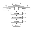
- FIG. 5 is a flowchart showing an operation state of the vehicle accelerator pedal depression pressure adjusting system 1 according to the second embodiment.
- the vehicle accelerator pedal depression pressure adjusting system 1 is turned on after the vehicle is started, or at the same time as the vehicle is started. .
- the weight of the driver sitting on the driver's seat is measured by the weight measuring device 31 (step S5), and the vehicle speed of the driving vehicle is detected by the vehicle speed detecting device 41 (step S6).
- the driver's weight information measured by the weight measuring device 31 and the vehicle speed information detected by the vehicle speed detecting device 41 are sent to the pedal pressure calculating device 32. Then, after the pedal pressure value of the accelerator pedal is calculated on the basis of the weight information in the pedal pressure calculation device 32 in the same procedure as in the first embodiment, the calculated pedal pressure value is based on the vehicle speed. The final step pressure value is determined after correction (step S7).
- step S8 the pedal pressure adjusting switch 10 is automatically operated by the switch variable device 33 in accordance with the corrected pedal pressure value obtained by the pedal pressure calculating device 32 (step S8).
- the stepping pressure control device 20 is activated according to the automatic operation of the stepping pressure adjustment switch 10, and the depression pressure of the accelerator pedal is controlled (step S9).
- steps S5 to S9 described above are continuously performed until the accelerator pedal depression pressure adjusting system 1 for the vehicle stops, that is, until the depression pressure operation switch is turned off or the vehicle stops the engine. Done.
- FIG. 7 is a block diagram showing a third embodiment of the vehicle accelerator pedal depression pressure adjusting system 1 according to the present invention.
- the vehicular accelerator pedal depression pressure adjusting system 1 according to the present embodiment includes an external condition detection device (external condition detection means) 51 in addition to the first embodiment.
- the outside condition detection device 51 is for detecting a driving condition in the outside of the vehicle.
- the accelerator pedal depressing force such as a road surface condition such as a wet state or a dry state on a traveling road surface, a road traveling on a slope, or the like. It is configured to detect various external conditions that affect the environment.
- the accelerator pedal depression pressure adjusting system 1 for a vehicle is based on the driver's weight measured by the weight measuring device 31 and the traveling condition information detected by the external condition detecting device 51, and the accelerator pedal depression pressure. Configured to determine a value.
- the calculation for determining the depression pressure value of the accelerator pedal is based on the depression pressure value calculated based on the body weight by the program shown in FIG. 3, for example, and the running condition information is obtained by the program shown in FIG. 9 or FIG. This is done by correcting the basic value on the basis of this.
- An example of correction based on driving conditions for the pedaling pressure value calculated based on the driver's weight which is the basic value, illustrates that the accelerator pedal pedaling pressure is lighter while driving downhill so that the accelerator pedal pressing pressure is lighter. Is corrected so that the accelerator pedal pressure is increased. Such correction is performed by a program written in advance in a ROM or the like.
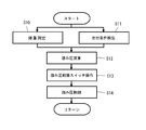
- FIG. 8 is a flowchart showing an operation state of the accelerator pedal depression pressure adjusting system 1 for a vehicle according to the third embodiment.
- the vehicle accelerator pedal depression pressure adjusting system 1 is turned on after the vehicle is started, or at the same time as the vehicle is started. .
- the weight of the driver sitting on the driver's seat is measured by the weight measuring device 31 (step S10), and the driving condition of the vehicle outside environment is detected by the outside condition detecting device 51 (step S11).
- the driver's weight information measured by the weight measuring device 31 and the traveling condition information detected by the external condition detecting device 51 are sent to the step pressure calculating device 32. Then, after the pedal pressure value of the accelerator pedal is calculated based on the weight information in the same procedure as in the first embodiment, the calculated pedal pressure value is based on the running condition. The final pedal pressure value is determined (step S12).
- the pedal pressure adjusting switch 10 is automatically operated by the switch variable device 33 according to the corrected pedal pressure value obtained by the pedal pressure calculating device 32 (step S13). Then, the stepping pressure control device 20 is activated according to the automatic operation of the stepping pressure adjustment switch 10, and the depression pressure of the accelerator pedal is controlled (step S14).
- steps S10 to S14 described above are continuously performed until the accelerator pedal depression pressure adjusting system 1 for the vehicle stops, that is, until the depression pressure operation switching switch is turned off or the vehicle stops the engine. Done.
- FIG. 11 is a block diagram showing a fourth embodiment of the accelerator pedal depression pressure adjusting system 1 for a vehicle according to the present invention.
- the vehicular accelerator pedal depression pressure adjusting system 1 according to the present embodiment is configured by combining the second to third embodiments. That is, the accelerator pedal depression pressure adjusting system 1 for a vehicle according to the present embodiment includes a weight measuring device 31, a vehicle speed detecting device 41, and an external condition detecting device 51, and a pedal pressure calculating device 32 and a switch variable.
- the apparatus 33 is provided.
- the vehicle accelerator pedal depression pressure adjusting system 1 includes a driver's weight measured by the weight measuring device 31, a vehicle speed detected by the vehicle speed detecting device 41, and a travel detected by the external condition detecting device 51.
- the accelerator pedal depression pressure value is determined based on the conditions.
- the calculation for determining the depression pressure value of the accelerator pedal is based on the depression pressure value calculated based on the body weight by the program shown in FIG. 3, for example, and the program shown in FIG. 6 or the program shown in FIG. 9 and FIG.
- the basic value is corrected based on the vehicle speed and the driving conditions.
- the vehicle speed is set so that the accelerator pedal pressure becomes heavy when the vehicle speed is faster than a predetermined value.
- the accelerator pedal depression pressure is corrected to be light.
- the accelerator pedal depression pressure is corrected so as to be light during traveling uphill, and the accelerator pedal depression pressure is increased during traveling downhill.
- FIG. 12 is a flowchart showing an operation state of the accelerator pedal depression pressure adjusting system 1 for a vehicle according to the fourth embodiment.
- the vehicle accelerator pedal depression pressure adjusting system 1 is started at the same time as turning on a depression pressure operation changeover switch provided in the vehicle after the vehicle is started, or at the same time as starting the vehicle.
- the weight of the driver sitting on the driver's seat is measured by the weight measuring device 31 (step S15), and the vehicle speed of the driving vehicle is detected by the vehicle speed detecting device 41 (step S16).
- the driving condition of the vehicle outside world is detected by the detection device 51 (step S17).
- the driver's weight information measured by the weight measuring device 31, the vehicle speed information detected by the vehicle speed detecting device 41, and the traveling condition information detected by the external condition detecting device 51 are used as a pedal pressure calculating device 32. Sent to. Then, after the pedal pressure value of the accelerator pedal is calculated based on the weight information in the pedal pressure calculation device 32 in the same procedure as in the first embodiment, the calculated pedal pressure value is determined based on the vehicle speed and the running condition. And the final pedal pressure value is determined (step S18).
- the pedal pressure adjusting switch 10 is automatically operated by the switch variable device 33 in accordance with the corrected pedal pressure value obtained by the pedal pressure calculating device 32 (step S19). Then, the pedal pressure control device 20 is activated according to the automatic operation of the pedal pressure adjustment switch 10, and the pedal pressure is controlled (step S20).
- steps S15 to S20 described above are continuously performed until the accelerator pedal depression pressure adjusting system 1 for the vehicle stops, that is, until the depression pressure operation changeover switch is turned off or the vehicle stops the engine. Done.
- the vehicle accelerator pedal depression pressure adjusting system 1 includes a vehicle accelerator pedal depression pressure according to driver information such as a driver's preference and weight, as well as a vehicle running state such as a vehicle speed and a road surface condition. Can be adjusted or adjusted automatically or manually, which contributes to reducing the driver's driving fatigue, suppresses a decrease in concentration while driving, and also causes accidents such as excessive depression of the accelerator pedal. Since prevention is achieved, it is understood that the industrial applicability of the present invention is great.
- Step pressure adjustment switch 20 Step pressure control device (step pressure control means) 31 Weight measuring device (weight measuring means) 32 Stepping pressure calculation device (stepping pressure calculation means) 33 Switch variable device (switch variable means) 41 Vehicle speed detection device (vehicle speed detection means) 51 External condition detection device (external condition detection means)
Landscapes
- Engineering & Computer Science (AREA)
- Power Engineering (AREA)
- Transportation (AREA)
- Mechanical Engineering (AREA)
- Life Sciences & Earth Sciences (AREA)
- Sustainable Development (AREA)
- Sustainable Energy (AREA)
- Auxiliary Drives, Propulsion Controls, And Safety Devices (AREA)
- Mechanical Control Devices (AREA)
Abstract
【課題】 運転者情報、車輌の走行状態に応じて、車輌用アクセルペダルの踏み圧を自動的若しくは手動的に可変・調節することが可能となるシステムの提供を図る。 【解決手段】 車輌におけるペダル踏み圧調節システムであって、踏み圧調節スイッチと、運転者の体重を測定する体重測定手段と、該体重測定手段により測定される体重が重くなるにつれ踏み圧が重くなるようにアクセルペダルの踏み圧値が決定される踏み圧演算手段と、該踏み圧演算手段により決定された踏み圧値に従い踏み圧調節スイッチを可変するスイッチ可変手段と、踏み圧調節スイッチに連動してアクセルペダルの踏み圧を制御する踏み圧制御手段とを備え、踏み圧調節スイッチを運転者の体重に応じて自動的に操作することでアクセルペダル踏み圧の軽重を制御する構成となっている。車速、車輌外界の走行条件を測定・検出し、その情報に基づき踏み圧値の補正を行う態様を採用し得る。
Description
本発明は、車輌用アクセルペダルの踏み圧を調節するためのシステムに関し、詳しくは、運転者情報、車輌の走行状態に応じて車輌用アクセルペダルの踏み圧を自動的若しくは手動的に可変・調節するための車輌用アクセルペダル踏み圧調節システムに関するものである。
車輌用ペダルの踏み圧は、メーカーや車種によって夫々任意に決定されており、軽いものから重いものまで様々である。アクセルペダルを例にとると、ほんの少し軽く踏み圧をかけただけで容易に踏み込める非常に軽い踏み圧のアクセルペダルを備える車輌もあれば、かなりの力を入れなければ踏み込めない程の重い踏み圧のアクセルペダルを備える車輌も存在する。このように車輌ごとに異なるペダルの踏み圧に対しては、運転者が自己調整により対応せざるを得ず、すなわち、乗車する車輌のペダル踏み圧に運転者自身が慣れていく若しくは合わせていく以外に、対応することができなかった。
運転に際し、例えば踏み圧の重いアクセルペダルを長時間にわたって踏み続けることは、運転者の疲労が増大する要因となる。また、アクセルペダルについては、運転中常に踏んだり放したりを繰り返すため、踏み圧が合わないと運転者の身体に負担が大きくなってしまう。さらに、運転の際に履く靴の種類・形状・重さ・底厚によっても、ペダルの踏み圧感覚が変わってきてしまう。そして、身体的疲労は運転者の集中力の低下にもつながるものであって、運転中における身体的負担の軽減のために、ペダル踏み圧が重要な役割を果たし得ると考えられる。
ところで、高速道路走行などに使用されるアクセルペダルを踏まなくとも一定速度で走行できる機能、いわゆるクルーズコントロール機能が搭載された車輌が存在する。この機能を使用してアクセルペダルから足を外すと、足先から腰に至るまで身体全体が楽になり、身体的疲労軽減に資するものとして多く普及している。このことからも判るように、ペダル操作のために同じ姿勢で足首などを動かし続けることが、運転者に身体的負担を強いている証左であり、よってペダルの踏み圧というのは、運転者の身体的疲労の軽減のために非常に重要な要素である。
運転者が、普段運転している車輌とは別の他の車輌を運転しようとする場合に、かかる車輌ごとに異なるペダルの踏み圧が問題となる。すなわち、普段から運転している車輌のペダル踏み圧に慣れてしまっている運転者が、他の車輌のペダル踏み圧に慣れるまでには時間を要するため、当初から踏み込み加減を最良にするのは難しく、普段運転している車輌と同じ様にペダルを踏み込んでしまうのが通例である。その場合に、思わずペダルを踏み込み過ぎたり、思うように踏み込めずに力が入り過ぎてしまったりして、スムーズな運転を阻害するのみならず、急発進や急ブレーキを起こす恐れがあり、それが原因で事故につながる危険性もある。さらには、普段慣れ親しんでいる運転車輌のペダル踏み圧と異なる他の車輌のペダル踏み圧に運転者が自己調整して合わせることは、その運転者に慣れない運転を強いることとなるため、運転者の疲労増大を招くことにもなる。
また、運転者の体型や体重によっても、車輌用ペダルの踏み圧が問題となる。例えば、体重45kg・身長150cmの女性と、体重100kg・身長200cm近い男性とが、同じ踏み圧の車輌用ペダルを操作するのには無理がある。
以上のように、様々な問題点を検証する中で、車輌用ペダルの踏み圧について調節を可能ならしめることで、かかる問題点の解決に資することができるものと思料される。
以上のように、様々な問題点を検証する中で、車輌用ペダルの踏み圧について調節を可能ならしめることで、かかる問題点の解決に資することができるものと思料される。
上記問題点に鑑み、本発明は、運転者情報、車輌の走行状態に応じて、車輌用アクセルペダルの踏み圧を自動的若しくは手動的に可変・調節することが可能となる車輌用アクセルペダル踏み圧調節システムを提供することを目的とするものである。
上記目的を達成するため、請求項1記載の本発明は、車輌用アクセルペダル踏み圧調節システムであって、踏み圧調節スイッチと、運転者の体重を測定する体重測定手段と、該体重測定手段により測定される体重が重くなるにつれ踏み圧が重くなるようにアクセルペダルの踏み圧値が決定される踏み圧演算手段と、該踏み圧演算手段により決定された踏み圧値に従い踏み圧調節スイッチを可変するスイッチ可変手段と、踏み圧調節スイッチに連動してアクセルペダルの踏み圧を制御する踏み圧制御手段とを備え、踏み圧調節スイッチを運転者の体重に応じて自動的に操作することでアクセルペダル踏み圧の軽重を制御する構成となっている。
また、請求項2記載の本発明は、前記踏み圧演算手段において、前記体重測定手段により測定される体重が所定の重さを超えた場合に、前記踏み圧値が一定の値に決定される構成を採用している。
さらに、請求項3記載の本発明は、前記踏み圧調節スイッチが、手動により操作可能である構成となっている。
またさらに、請求項4記載の本発明は、前記車輌用アクセルペダル踏み圧調節システムにおいて、車速を検出する車速検出手段を備え、前記踏み圧演算手段において、該車速検出手段により検出された車速情報に基づきアクセルペダルの踏み圧値が補正される構成を採る。
さらにまた、請求項5記載の本発明は、前記車輌用アクセルペダル踏み圧調節システムにおいて、車輌外界の走行条件を検出する外界条件検出手段を備え、前記踏み圧演算手段において、該外界条件検出手段により検出された走行条件情報に基づきアクセルペダルの踏み圧値が補正される構成となっている。
本発明にかかる車輌用アクセルペダル踏み圧調節システムによれば、運転者情報、車輌の走行状態に応じて車輌用アクセルペダルの踏み圧を自動的若しくは手動的に可変・調節することが可能となり、運転者の運転疲労の軽減に資するとともに、運転中の集中力減退を抑制し、さらには、アクセルペダルの踏み込み過ぎ等による事故防止を図ることが可能となる。
本発明にかかる車輌用アクセルペダル踏み圧調節システムは、運転者情報(体重)、さらには車速や路面状況等といった車輌の走行状態に応じて、車輌用アクセルペダルの踏み圧を自動的若しくは手動的に可変・調節することを可能としたことを最大の特徴とする。以下、本発明にかかる車輌用アクセルペダル踏み圧調節システムの実施形態を図面に基づいて説明する。
なお、本発明は、下記の実施形態に示した構成に特に限定されるものではなく、本発明の技術的思想の要旨に逸脱しない範囲で任意に変更することができるものである。
図1は、本発明に係る車輌用アクセルペダル踏み圧調節システム1の基本となる第一の実施形態を示すブロック図である。
本実施形態に係る車輌用アクセルペダル踏み圧調節システム1は、踏み圧調節スイッチ10と、体重測定装置(体重測定手段)31と、踏み圧演算装置(踏み圧演算手段)32と、スイッチ可変装置(スイッチ可変手段)33と、踏み圧制御装置(踏み圧制御手段)20と、を備えてなる。
本実施形態に係る車輌用アクセルペダル踏み圧調節システム1は、踏み圧調節スイッチ10と、体重測定装置(体重測定手段)31と、踏み圧演算装置(踏み圧演算手段)32と、スイッチ可変装置(スイッチ可変手段)33と、踏み圧制御装置(踏み圧制御手段)20と、を備えてなる。
踏み圧調節スイッチ10は、後述する踏み圧制御装置20を起動・制御するための操作スイッチである。該踏み圧調節スイッチ10は、ボタン式構造やダイヤル式構造等からなり、後述するスイッチ可変装置33により自動的に該踏み圧調節スイッチ10が可変操作されることにより、段階的にアクセルペダルの踏み圧の軽重を可変するための操作スイッチとして作用する。該踏み圧調節スイッチ10の切替における段階数については特に限定はなく、例えば3乃至4段階切替とする態様や、あるいは、無段階切替式とする態様が考え得る。
体重測定装置31は、運転者の体重を測定するためのものであって、運転席の座面内部に該体重の測定装置が内蔵され、そこに着座した運転手の体重を測定する構成となっている。
踏み圧演算装置32は、前記体重測定装置31により測定された運転者の体重に基づいて、アクセルペダルの踏み圧値を決定するように構成されている。なお、アクセルペダルの踏み圧値を決定する演算は、図3に示すように、予めROM等に書き込まれたプログラムにより行われる。
かかるアクセルペダルの踏み圧値の演算について、具体的には、図3に示すように、前記体重測定装置31により測定された体重が重くなるにつれ、踏み圧が重くなるようにアクセルペダルの踏み圧値が決定されることとなる。
なお、アクセルペダルの踏み圧値が無限に重くなることのないよう、前記体重測定装置31により測定される体重が所定の重さを超えた場合には、図3に示すように、前記踏み圧値を一定の値に決定よう態様が望ましい。
なお、アクセルペダルの踏み圧値が無限に重くなることのないよう、前記体重測定装置31により測定される体重が所定の重さを超えた場合には、図3に示すように、前記踏み圧値を一定の値に決定よう態様が望ましい。
スイッチ可変装置33は、前記踏み圧演算装置32によって求められた踏み圧値に従って、前記踏み圧調節スイッチ10を自動的に可変操作する構成となっている。
踏み圧制御装置20は、前記踏み圧調節スイッチ10の操作に連動して、アクセルペダルの踏み圧の軽重を可変するための制御部として作用する。一般的な車輌におけるアクセルペダル操作の伝達機構は、油圧式や電気信号式が採用されており、アクセルペダルの踏み込み操作により該油圧式伝達機構や電気信号式伝達機構を介して車輌の各制御が行われることとなるが、この油圧の調整や電気信号の調整を、前記踏み圧調節スイッチ10の操作に連動して、本踏み圧制御装置20が行うこととなる。
この車輌用アクセルペダル踏み圧調節システム1は、車輌を始動した後に車内に設けられた踏み圧操作切換スイッチをオンにすることにより、踏み圧調節スイッチ10を自動で操作可能な状態として、通常のペダル踏み圧から調節を行うことができる態様が可能であり、あるいは、車輌を始動したと同時に、踏み圧操作切換スイッチ等と関係なく、いきなり踏み圧調節スイッチ10を自動で操作可能な状態として、通常のアクセルペダル踏み圧から調節を行うことができる態様も考え得る。
次に、上述した車輌用アクセルペダル踏み圧調節システム1の一動作例について、図面を参照しながら説明する。
図2は、第一の実施形態に係る車輌用アクセルペダル踏み圧調節システム1の動作状況を示すフローチャートである。
図2は、第一の実施形態に係る車輌用アクセルペダル踏み圧調節システム1の動作状況を示すフローチャートである。
この車輌用アクセルペダル踏み圧調節システム1は、車輌始動後に車内に設けられた踏み圧操作切換スイッチをオンにするか、あるいは、車輌の始動と同時に、スタートする。
スタート後、体重測定装置31により、運転席に着座している運転手の体重が測定される(ステップS1)。
次に、体重測定装置31により測定された運転手の体重情報が、踏み圧演算装置32に送られ、該踏み圧演算装置32において、図5に示す演算方法により、その体重情報に基づいて、アクセルペダルの踏み圧値が決定される(ステップS2)。
スタート後、体重測定装置31により、運転席に着座している運転手の体重が測定される(ステップS1)。
次に、体重測定装置31により測定された運転手の体重情報が、踏み圧演算装置32に送られ、該踏み圧演算装置32において、図5に示す演算方法により、その体重情報に基づいて、アクセルペダルの踏み圧値が決定される(ステップS2)。
次に、踏み圧演算装置32により求められた踏み圧値に応じて、スイッチ可変装置33により前記踏み圧調節スイッチ10が自動的に操作される(ステップS3)。
そして、踏み圧調節スイッチ10の自動操作に応じて踏み圧制御装置20が作動して、アクセルペダルの踏み圧が制御される(ステップS4)。
そして、踏み圧調節スイッチ10の自動操作に応じて踏み圧制御装置20が作動して、アクセルペダルの踏み圧が制御される(ステップS4)。
上述したステップS1~S4における処理は、車輌用アクセルペダル踏み圧調節システム1が停止するまで、すなわち、踏み圧操作切換スイッチをオフにするか、あるいは、車輌がエンジンストップするまで連続して行なわれる。
なお、本発明に係る車輌用アクセルペダル踏み圧調節システム1において、前記スイッチ可変装置33による前記踏み圧調節スイッチ10の自動可変操作に加え、該踏み圧調節スイッチ10について手動により切替操作を可能とする態様も考え得る。
ところで、本発明に、当該運転者に合ったアクセルペダル踏み圧を記憶する運転者情報記憶装置(運転者情報記憶手段)を備える態様も考え得る。
該運転者情報記憶装置は、既に車輌に採用されている運転者ごとの座席位置情報や各ミラー位置情報、ハンドル位置情報などを記憶しておくための記憶装置を利用すれば足り、運転者指定スイッチを備え、該運転者指定スイッチに連動して踏み圧調節スイッチ10を可変するスイッチ可変装置(スイッチ可変手段)が備えられた構成となっている。
該運転者情報記憶装置は、既に車輌に採用されている運転者ごとの座席位置情報や各ミラー位置情報、ハンドル位置情報などを記憶しておくための記憶装置を利用すれば足り、運転者指定スイッチを備え、該運転者指定スイッチに連動して踏み圧調節スイッチ10を可変するスイッチ可変装置(スイッチ可変手段)が備えられた構成となっている。
運転者指定スイッチは、運転者の好みのアクセルペダル踏み圧値を記憶操作したり、あるいは記憶されたアクセルペダル踏み圧値を呼び出すためのものであって、運転者ごとに一乃至複数のスイッチ部を有するように構成される。そして、前記踏み圧調節スイッチ10を自動的若しくは手動操作により好みの踏み圧に合わせた状態で、座席位置情報等を記憶するための従来の記憶操作同様、所定のスイッチ部を長押しするなどして、該当運転手の好みのアクセルペダル踏み圧を記憶させる構成となっている。
スイッチ可変装置は、前記運転者指定スイッチによって呼び出された踏み圧値に従って、前記踏み圧調節スイッチ10を自動的に可変操作する構成となっている。
かかる運転者情報記憶装置を備えることにより、運転当初から予め記憶された運転者の好みの踏み圧にセッティングすることが可能となり、踏み圧調節スイッチ10が一々操作されて好みの踏み圧に合わせられる作業を短縮することが可能となる。
図4は、本発明に係る車輌用アクセルペダル踏み圧調節システム1の第二の実施形態を示すブロック図である。
本実施形態に係る車輌用アクセルペダル踏み圧調節システム1は、上記第一の実施形態に加え、車速検出装置(車速検出手段)41を備えてなる。
本実施形態に係る車輌用アクセルペダル踏み圧調節システム1は、上記第一の実施形態に加え、車速検出装置(車速検出手段)41を備えてなる。
車速検出装置41は、運転車輌の車速を検出するためのものであって、車速検出センサを備え、ミッションに取り付けるパルスジェネレータの回転に応じて発生した誘導電流を検出し、所定の波形修正回路を経て求めることにより、車速を検出するように構成されている。
本実施形態に係る車輌用アクセルペダル踏み圧調節システム1は、体重測定装置31で測定した運転者の体重と、車速検出装置41で検出された車速に基づいて、アクセルペダルの踏み圧値を決定するように構成されている。
ここで、アクセルペダルの踏み圧値を決定する演算は、例えば図3に示すプログラムにより体重に基づいて算出した踏み圧値を基本値とし、図6に示すプログラムにより、車速に基づいて該基本値を補正することで行われる。
基本値である運転者の体重に基づいて算出した踏み圧値に対し、車速条件による補正例について例示すると、車速が所定値よりも速い場合にはアクセルペダル踏み圧が重くなるように、車速が所定値よりも遅い場合にはアクセルペダル踏み圧が軽くなるように補正される。かかる補正は、予めROM等に書き込まれたプログラムにより行われる。
次に、上述した車輌用アクセルペダル踏み圧調節システム1の一動作例について、図面を参照しながら説明する。
図5は、第二の実施形態に係る車輌用アクセルペダル踏み圧調節システム1の動作状況を示すフローチャートである。
図5は、第二の実施形態に係る車輌用アクセルペダル踏み圧調節システム1の動作状況を示すフローチャートである。
この車輌用アクセルペダル踏み圧調節システム1は、上記第一の実施形態と同様、車輌始動後に車内に設けられた踏み圧操作切換スイッチをオンにするか、あるいは、車輌の始動と同時に、スタートする。
スタート後、体重測定装置31により運転席に着座している運転手の体重が測定される(ステップS5)とともに、車速検出装置41により運転車輌の車速が検出される(ステップS6)。
スタート後、体重測定装置31により運転席に着座している運転手の体重が測定される(ステップS5)とともに、車速検出装置41により運転車輌の車速が検出される(ステップS6)。
次に、体重測定装置31により測定された運転手の体重情報と、車速検出装置41により検出された車速情報とが、踏み圧演算装置32に送られる。そして、該踏み圧演算装置32において、上記第一の実施形態と同様の手順で、体重情報に基づきアクセルペダルの踏み圧値が算出された後、その算出された踏み圧値が車速に基づいて補正され、最終的な踏み圧値が決定される(ステップS7)。
次に、踏み圧演算装置32により求められた補正後の踏み圧値に応じて、スイッチ可変装置33により前記踏み圧調節スイッチ10が自動的に操作される(ステップS8)。
そして、踏み圧調節スイッチ10の自動操作に応じて踏み圧制御装置20が作動して、アクセルペダルの踏み圧が制御される(ステップS9)。
そして、踏み圧調節スイッチ10の自動操作に応じて踏み圧制御装置20が作動して、アクセルペダルの踏み圧が制御される(ステップS9)。
なお、上述したステップS5~S9における処理は、車輌用アクセルペダル踏み圧調節システム1が停止するまで、すなわち、踏み圧操作切換スイッチをオフにするか、あるいは、車輌がエンジンストップするまで連続して行なわれる。
図7は、本発明に係る車輌用アクセルペダル踏み圧調節システム1の第三の実施形態を示すブロック図である。
本実施形態に係る車輌用アクセルペダル踏み圧調節システム1は、上記第一の実施形態に加え、外界条件検出装置(外界条件検出手段)51を備えてなる。
本実施形態に係る車輌用アクセルペダル踏み圧調節システム1は、上記第一の実施形態に加え、外界条件検出装置(外界条件検出手段)51を備えてなる。
外界条件検出装置51は、車輌外界の走行条件を検出するためのものであって、具体的には、走行路面についてウェット状態若しくはドライ状態といった路面状況や、坂道走行等といった、アクセルペダルの踏み込み力に影響を与える種々の外界条件を検出するように構成されている。
本実施形態に係る車輌用アクセルペダル踏み圧調節システム1は、体重測定装置31で測定した運転者の体重と、外界条件検出装置51で検出された走行条件情報に基づいて、アクセルペダルの踏み圧値を決定するように構成されている。
ここで、アクセルペダルの踏み圧値を決定する演算は、例えば図3に示すプログラムにより体重に基づいて算出した踏み圧値を基本値とし、図9や図10に示すプログラムにより、走行条件情報に基づいて該基本値を補正することで行われる。
基本値である運転者の体重に基づいて算出した踏み圧値に対し、走行条件による補正例について例示すると、上り坂を走行中にはアクセルペダル踏み圧が軽くなるように、下り坂を走行中にはアクセルペダル踏み圧が重くなるように補正される。かかる補正は、予めROM等に書き込まれたプログラムにより行われる。
次に、上述した車輌用アクセルペダル踏み圧調節システム1の一動作例について、図面を参照しながら説明する。
図8は、第三の実施形態に係る車輌用アクセルペダル踏み圧調節システム1の動作状況を示すフローチャートである。
図8は、第三の実施形態に係る車輌用アクセルペダル踏み圧調節システム1の動作状況を示すフローチャートである。
この車輌用アクセルペダル踏み圧調節システム1は、上記第一の実施形態と同様、車輌始動後に車内に設けられた踏み圧操作切換スイッチをオンにするか、あるいは、車輌の始動と同時に、スタートする。
スタート後、体重測定装置31により運転席に着座している運転手の体重が測定される(ステップS10)とともに、外界条件検出装置51により車輌外界の走行条件が検出される(ステップS11)。
スタート後、体重測定装置31により運転席に着座している運転手の体重が測定される(ステップS10)とともに、外界条件検出装置51により車輌外界の走行条件が検出される(ステップS11)。
次に、体重測定装置31により測定された運転手の体重情報と、外界条件検出装置51により検出された走行条件情報とが、踏み圧演算装置32に送られる。そして、該踏み圧演算装置32において、上記第一の実施形態と同様の手順で、体重情報に基づきアクセルペダルの踏み圧値が算出された後、その算出された踏み圧値が走行条件に基づいて補正され、最終的な踏み圧値が決定される(ステップS12)。
次に、踏み圧演算装置32により求められた補正後の踏み圧値に応じて、スイッチ可変装置33により前記踏み圧調節スイッチ10が自動的に操作される(ステップS13)。
そして、踏み圧調節スイッチ10の自動操作に応じて踏み圧制御装置20が作動して、アクセルペダルの踏み圧が制御される(ステップS14)。
そして、踏み圧調節スイッチ10の自動操作に応じて踏み圧制御装置20が作動して、アクセルペダルの踏み圧が制御される(ステップS14)。
なお、上述したステップS10~S14における処理は、車輌用アクセルペダル踏み圧調節システム1が停止するまで、すなわち、踏み圧操作切換スイッチをオフにするか、あるいは、車輌がエンジンストップするまで連続して行なわれる。
図11は、本発明に係る車輌用アクセルペダル踏み圧調節システム1の第四の実施形態を示すブロック図である。
本実施形態に係る車輌用アクセルペダル踏み圧調節システム1は、上記第二乃至第三の実施形態を組み合わせた構成となっている。すなわち、本実施形態に係る車輌用アクセルペダル踏み圧調節システム1は、体重測定装置31と、車速検出装置41と、外界条件検出装置51とを備えているとともに、踏み圧演算装置32及びスイッチ可変装置33が備えられた構成となっている。
本実施形態に係る車輌用アクセルペダル踏み圧調節システム1は、上記第二乃至第三の実施形態を組み合わせた構成となっている。すなわち、本実施形態に係る車輌用アクセルペダル踏み圧調節システム1は、体重測定装置31と、車速検出装置41と、外界条件検出装置51とを備えているとともに、踏み圧演算装置32及びスイッチ可変装置33が備えられた構成となっている。
本実施形態に係る車輌用アクセルペダル踏み圧調節システム1は、体重測定装置31で測定した運転者の体重と、車速検出装置41で検出された車速と、外界条件検出装置51により検出された走行条件に基づいて、アクセルペダルの踏み圧値を決定するように構成されている。
ここで、アクセルペダルの踏み圧値を決定する演算は、例えば図3に示すプログラムにより体重に基づいて算出した踏み圧値を基本値とし、図6に示すプログラムや図9及び図10に示すプログラムにより、車速や走行条件に基づいて該基本値を補正することで行われる。
基本値である運転者の体重に基づいて算出した踏み圧値に対し、他の条件による補正例について例示すると、車速が所定値よりも速い場合にはアクセルペダル踏み圧が重くなるように、車速が所定値よりも遅い場合にはアクセルペダル踏み圧が軽くなるように補正される。また、上り坂を走行中にはアクセルペダル踏み圧が軽くなるように、下り坂を走行中にはアクセルペダル踏み圧が重くなるように補正される。これらの補正は、予めROM等に書き込まれたプログラムにより行われる。
次に、上述した車輌用アクセルペダル踏み圧調節システム1の一動作例について、図面を参照しながら説明する。
図12は、第四の実施形態に係る車輌用アクセルペダル踏み圧調節システム1の動作状況を示すフローチャートである。
図12は、第四の実施形態に係る車輌用アクセルペダル踏み圧調節システム1の動作状況を示すフローチャートである。
この車輌用アクセルペダル踏み圧調節システム1は、上記各実施形態と同様、車輌始動後に車内に設けられた踏み圧操作切換スイッチをオンにするか、あるいは、車輌の始動と同時に、スタートする。
スタート後、体重測定装置31により運転席に着座している運転手の体重が測定される(ステップS15)とともに、車速検出装置41により運転車輌の車速が検出され(ステップS16)、また、外界条件検出装置51により車輌外界の走行条件が検出される(ステップS17)。
スタート後、体重測定装置31により運転席に着座している運転手の体重が測定される(ステップS15)とともに、車速検出装置41により運転車輌の車速が検出され(ステップS16)、また、外界条件検出装置51により車輌外界の走行条件が検出される(ステップS17)。
次に、体重測定装置31により測定された運転手の体重情報と、車速検出装置41により検出された車速情報と、外界条件検出装置51により検出された走行条件情報とが、踏み圧演算装置32に送られる。そして、該踏み圧演算装置32において、上記第一の実施形態と同様の手順で、体重情報に基づきアクセルペダルの踏み圧値が算出された後、その算出された踏み圧値が車速並びに走行条件に基づいて補正され、最終的な踏み圧値が決定される(ステップS18)。
次に、踏み圧演算装置32により求められた補正後の踏み圧値に応じて、スイッチ可変装置33により前記踏み圧調節スイッチ10が自動的に操作される(ステップS19)。
そして、踏み圧調節スイッチ10の自動操作に応じて踏み圧制御装置20が作動して、ペダルの踏み圧が制御される(ステップS20)。
そして、踏み圧調節スイッチ10の自動操作に応じて踏み圧制御装置20が作動して、ペダルの踏み圧が制御される(ステップS20)。
なお、上述したステップS15~S20における処理は、車輌用アクセルペダル踏み圧調節システム1が停止するまで、すなわち、踏み圧操作切換スイッチをオフにするか、あるいは、車輌がエンジンストップするまで連続して行なわれる。
本発明に係る車輌用アクセルペダル踏み圧調節システム1は、運転者の好みや体重などの運転者情報、さらには車速や路面状況等といった車輌の走行状態に応じて、車輌用アクセルペダルの踏み圧を自動的若しくは手動的に可変・調節することが可能であるため、運転者の運転疲労の軽減に資するとともに、運転中の集中力減退を抑制し、さらには、アクセルペダルの踏み込み過ぎ等による事故防止が図られることから、本発明の産業上の利用可能性は大であると解する。
1 車輌用アクセルペダル踏み圧調節システム
10 踏み圧調節スイッチ
20 踏み圧制御装置(踏み圧制御手段)
31 体重測定装置(体重測定手段)
32 踏み圧演算装置(踏み圧演算手段)
33 スイッチ可変装置(スイッチ可変手段)
41 車速検出装置(車速検出手段)
51 外界条件検出装置(外界条件検出手段)
10 踏み圧調節スイッチ
20 踏み圧制御装置(踏み圧制御手段)
31 体重測定装置(体重測定手段)
32 踏み圧演算装置(踏み圧演算手段)
33 スイッチ可変装置(スイッチ可変手段)
41 車速検出装置(車速検出手段)
51 外界条件検出装置(外界条件検出手段)
Claims (5)
- 車輌におけるアクセルペダル踏み圧調節システムであって、
踏み圧調節スイッチと、運転者の体重を測定する体重測定手段と、該体重測定手段により測定される体重が重くなるにつれ踏み圧が重くなるようにアクセルペダルの踏み圧値が決定される踏み圧演算手段と、該踏み圧演算手段により決定された踏み圧値に従い踏み圧調節スイッチを可変するスイッチ可変手段と、踏み圧調節スイッチに連動してアクセルペダルの踏み圧を制御する踏み圧制御手段とを備え、
踏み圧調節スイッチを運転者の体重に応じて自動的に操作することでペダル踏み圧の軽重を制御することを特徴とする車輌用アクセルペダル踏み圧調節システム。 - 前記踏み圧演算手段において、前記体重測定手段により測定される体重が所定の重さを超えた場合に、前記踏み圧値が一定の値に決定されることを特徴とする請求項1に記載の車輌用アクセルペダル踏み圧調節システム。
- 前記踏み圧調節スイッチが、手動により操作可能であることを特徴とする請求項1または請求項2に記載の車輌用アクセルペダル踏み圧調節システム。
- 前記車輌用アクセルペダル踏み圧調節システムにおいて、
車速を検出する車速検出手段を備え、
前記踏み圧演算手段において、該車速検出手段により検出された車速情報に基づきアクセルペダルの踏み圧値が補正されることを特徴とする請求項1から請求項3のいずれかに記載の車輌用アクセルペダル踏み圧調節システム。 - 前記車輌用アクセルペダル踏み圧調節システムにおいて、
車輌外界の走行条件を検出する外界条件検出手段を備え、
前記踏み圧演算手段において、該外界条件検出手段により検出された走行条件情報に基づきアクセルペダルの踏み圧値が補正されることを特徴とする請求項1から請求項4のいずれかに記載の車輌用アクセルペダル踏み圧調節システム。
Priority Applications (1)
| Application Number | Priority Date | Filing Date | Title |
|---|---|---|---|
| EP12793595.5A EP2717113A4 (en) | 2011-06-02 | 2012-06-01 | PRESSURE REGULATION SYSTEM FOR PRESSING THE ACCELERATOR PEDAL OF A RAIL VEHICLE |
Applications Claiming Priority (2)
| Application Number | Priority Date | Filing Date | Title |
|---|---|---|---|
| JP2011124563A JP4881482B1 (ja) | 2011-06-02 | 2011-06-02 | 車輌用アクセルペダル踏み圧調節システム |
| JP2011-124563 | 2011-06-02 |
Publications (1)
| Publication Number | Publication Date |
|---|---|
| WO2012165622A1 true WO2012165622A1 (ja) | 2012-12-06 |
Family
ID=45851230
Family Applications (1)
| Application Number | Title | Priority Date | Filing Date |
|---|---|---|---|
| PCT/JP2012/064298 WO2012165622A1 (ja) | 2011-06-02 | 2012-06-01 | 車輌用アクセルペダル踏み圧調節システム |
Country Status (3)
| Country | Link |
|---|---|
| EP (1) | EP2717113A4 (ja) |
| JP (1) | JP4881482B1 (ja) |
| WO (1) | WO2012165622A1 (ja) |
Families Citing this family (2)
| Publication number | Priority date | Publication date | Assignee | Title |
|---|---|---|---|---|
| JP6631577B2 (ja) | 2017-04-05 | 2020-01-15 | 株式会社デンソー | 運転交代制御システム、運転交代制御プログラム、及び運転交代制御方法 |
| CN110500188B (zh) * | 2019-08-21 | 2022-02-18 | 洛阳市黄河软轴控制器股份有限公司 | 手油门协调控制系统及其控制方法 |
Citations (5)
| Publication number | Priority date | Publication date | Assignee | Title |
|---|---|---|---|---|
| JPH0951603A (ja) | 1995-08-07 | 1997-02-18 | Toyota Motor Corp | 電気車両の制動装置 |
| JP2001322538A (ja) * | 2000-05-15 | 2001-11-20 | Hitachi Ltd | 自動車の走行制御装置及び自動車 |
| JP2003260951A (ja) * | 2002-03-07 | 2003-09-16 | Alps Electric Co Ltd | 車両の運転制御装置 |
| JP2005082041A (ja) * | 2003-09-09 | 2005-03-31 | Toyota Motor Corp | 車両用自動ブレーキ装置 |
| JP2011060099A (ja) * | 2009-09-11 | 2011-03-24 | Advics Co Ltd | ペダル装置 |
Family Cites Families (17)
| Publication number | Priority date | Publication date | Assignee | Title |
|---|---|---|---|---|
| DE3347070A1 (de) * | 1983-12-24 | 1985-07-04 | Westfälische Metall Industrie KG Hueck & Co, 4780 Lippstadt | Vorrichtung zum regeln der geschwindigkeit eines kraftfahrzeuges |
| JP2928514B2 (ja) * | 1987-08-19 | 1999-08-03 | 株式会社日立製作所 | エンジン動作制御方法および自動車 |
| JPH0192537A (ja) * | 1987-10-01 | 1989-04-11 | Mitsubishi Electric Corp | 車輌のアクセルペダル装置 |
| JP2658467B2 (ja) * | 1990-01-22 | 1997-09-30 | 日産自動車株式会社 | アクセル反力制御装置 |
| JP3669036B2 (ja) * | 1996-03-18 | 2005-07-06 | 日産自動車株式会社 | 登降坂によるアクセル反力制御装置 |
| JP3982456B2 (ja) * | 2003-06-04 | 2007-09-26 | 日産自動車株式会社 | 車両用リスクポテンシャル算出装置、車両用運転操作補助装置、車両用運転操作補助装置を備える車両およびリスクポテンシャル算出方法 |
| DE10356834A1 (de) * | 2003-12-05 | 2005-06-30 | Robert Bosch Gmbh | Verfahren und Vorrichtung zur Einstellung der auf eine Fahrpedaleinrichtung wirkenden Rückstellkraft |
| JP4980576B2 (ja) * | 2005-03-31 | 2012-07-18 | 日立オートモティブシステムズ株式会社 | ペダル装置及びそれを備えた自動車 |
| JP4873610B2 (ja) * | 2005-11-16 | 2012-02-08 | Udトラックス株式会社 | 省燃費運転システム |
| JP5148368B2 (ja) * | 2008-05-27 | 2013-02-20 | 本田技研工業株式会社 | 車両走行制御装置及び車両走行制御方法 |
| JP5381321B2 (ja) * | 2008-07-31 | 2014-01-08 | 日産自動車株式会社 | アクセルペダル踏力制御装置 |
| JP4553057B2 (ja) * | 2008-07-31 | 2010-09-29 | 日産自動車株式会社 | アクセルペダル踏力制御装置および方法 |
| KR101091506B1 (ko) * | 2008-12-05 | 2011-12-08 | 현대자동차주식회사 | 답력가변형 가속페달장치 |
| JP5375557B2 (ja) * | 2009-03-27 | 2013-12-25 | 日産自動車株式会社 | 車両用アクセルペダル反力付与装置及びその方法 |
| JP5446654B2 (ja) * | 2009-09-18 | 2014-03-19 | 日産自動車株式会社 | アクセルペダル踏力制御装置 |
| DE102009045512A1 (de) * | 2009-10-09 | 2011-04-14 | Robert Bosch Gmbh | Steuergerät und ein Verfahren zum Auswählen einer Widerstandskennlinie eines Fahrpedals |
| AT508697B1 (de) * | 2010-12-02 | 2014-06-15 | Avl List Gmbh | Verfahren und eine vorrichtung zum regeln der fahrgeschwindigkeit eines kraftfahrzeuges |
-
2011
- 2011-06-02 JP JP2011124563A patent/JP4881482B1/ja not_active Expired - Fee Related
-
2012
- 2012-06-01 WO PCT/JP2012/064298 patent/WO2012165622A1/ja active Application Filing
- 2012-06-01 EP EP12793595.5A patent/EP2717113A4/en not_active Withdrawn
Patent Citations (5)
| Publication number | Priority date | Publication date | Assignee | Title |
|---|---|---|---|---|
| JPH0951603A (ja) | 1995-08-07 | 1997-02-18 | Toyota Motor Corp | 電気車両の制動装置 |
| JP2001322538A (ja) * | 2000-05-15 | 2001-11-20 | Hitachi Ltd | 自動車の走行制御装置及び自動車 |
| JP2003260951A (ja) * | 2002-03-07 | 2003-09-16 | Alps Electric Co Ltd | 車両の運転制御装置 |
| JP2005082041A (ja) * | 2003-09-09 | 2005-03-31 | Toyota Motor Corp | 車両用自動ブレーキ装置 |
| JP2011060099A (ja) * | 2009-09-11 | 2011-03-24 | Advics Co Ltd | ペダル装置 |
Non-Patent Citations (1)
| Title |
|---|
| See also references of EP2717113A4 * |
Also Published As
| Publication number | Publication date |
|---|---|
| JP4881482B1 (ja) | 2012-02-22 |
| EP2717113A4 (en) | 2016-01-06 |
| EP2717113A1 (en) | 2014-04-09 |
| JP2012252515A (ja) | 2012-12-20 |
Similar Documents
| Publication | Publication Date | Title |
|---|---|---|
| EP0553192B1 (en) | Operation of servo devices for driving a motor vehicle-control, arrangement and method | |
| JP5644684B2 (ja) | 異常時対応運転制御の要否判定方法および異常時対応運転制御の要否判定に基づく運転制御装置 | |
| EP2705973B1 (en) | Straddle-type electric vehicle, power unit, and method for controlling power unit | |
| JP4103814B2 (ja) | 定速走行制御装置 | |
| JP2008044395A (ja) | 車両の高度制御装置 | |
| JP2015506863A (ja) | 座席情報に基づく車両内の触覚式アクセルペダルの制御方法及び制御装置 | |
| JP4921990B2 (ja) | 車両のヨーモーメント制御装置 | |
| JP3633744B2 (ja) | 車両の走行制御装置 | |
| JP4881482B1 (ja) | 車輌用アクセルペダル踏み圧調節システム | |
| US10471957B2 (en) | Vehicle control apparatus capable of giving continuity to reactive perception quantities of cooperative operation perceived by occupant | |
| US20050090963A1 (en) | Device for controlling at least one control and/or regulating system arranged in a vehicle | |
| JP2004140949A (ja) | 圧力分布パターンによる走行制御装置 | |
| JP2007112359A (ja) | 車両の走行制御装置 | |
| KR20140045830A (ko) | 노면의 마찰력에 따른 mdps의 조향감 변경방법 및 그 장치 | |
| JP2007253664A (ja) | 車両用運転姿勢調節装置、運転姿勢調節方法および運転姿勢調節装置付き車両 | |
| JP2734213B2 (ja) | ペダル調整装置 | |
| JP3370197B2 (ja) | 自動車の車速制御装置 | |
| CN107415930B (zh) | 车辆的控制装置 | |
| JP4223261B2 (ja) | 圧力分布パターンによる駆動制御装置 | |
| KR20140073097A (ko) | 차량용 가속페달의 킥 다운 제어장치 및 방법 | |
| JP2020072491A (ja) | 移動体 | |
| JP2004138547A (ja) | 荷重分布による駆動制御装置 | |
| JP2008168839A (ja) | 車両のヨーモーメント制御装置 | |
| JP2005239117A (ja) | 運転者感情誘導装置 | |
| JP2023028315A (ja) | 車両の運転補助装置 |
Legal Events
| Date | Code | Title | Description |
|---|---|---|---|
| 121 | Ep: the epo has been informed by wipo that ep was designated in this application |
Ref document number: 12793595 Country of ref document: EP Kind code of ref document: A1 |
|
| NENP | Non-entry into the national phase |
Ref country code: DE |
|
| REEP | Request for entry into the european phase |
Ref document number: 2012793595 Country of ref document: EP |
|
| WWE | Wipo information: entry into national phase |
Ref document number: 2012793595 Country of ref document: EP |