WO2012165527A1 - ウインドレギュレータ - Google Patents
ウインドレギュレータ Download PDFInfo
- Publication number
- WO2012165527A1 WO2012165527A1 PCT/JP2012/064032 JP2012064032W WO2012165527A1 WO 2012165527 A1 WO2012165527 A1 WO 2012165527A1 JP 2012064032 W JP2012064032 W JP 2012064032W WO 2012165527 A1 WO2012165527 A1 WO 2012165527A1
- Authority
- WO
- WIPO (PCT)
- Prior art keywords
- wire
- locking piece
- housing
- window regulator
- guide
- Prior art date
- Legal status (The legal status is an assumption and is not a legal conclusion. Google has not performed a legal analysis and makes no representation as to the accuracy of the status listed.)
- Ceased
Links
Images


Classifications
-
- E—FIXED CONSTRUCTIONS
- E05—LOCKS; KEYS; WINDOW OR DOOR FITTINGS; SAFES
- E05F—DEVICES FOR MOVING WINGS INTO OPEN OR CLOSED POSITION; CHECKS FOR WINGS; WING FITTINGS NOT OTHERWISE PROVIDED FOR, CONCERNED WITH THE FUNCTIONING OF THE WING
- E05F11/00—Man-operated mechanisms for operating wings, including those which also operate the fastening
- E05F11/38—Man-operated mechanisms for operating wings, including those which also operate the fastening for sliding windows, e.g. vehicle windows, to be opened or closed by vertical movement
- E05F11/48—Man-operated mechanisms for operating wings, including those which also operate the fastening for sliding windows, e.g. vehicle windows, to be opened or closed by vertical movement operated by cords or chains or other flexible elongated pulling elements, e.g. tapes
- E05F11/481—Man-operated mechanisms for operating wings, including those which also operate the fastening for sliding windows, e.g. vehicle windows, to be opened or closed by vertical movement operated by cords or chains or other flexible elongated pulling elements, e.g. tapes for vehicle windows
- E05F11/483—Man-operated mechanisms for operating wings, including those which also operate the fastening for sliding windows, e.g. vehicle windows, to be opened or closed by vertical movement operated by cords or chains or other flexible elongated pulling elements, e.g. tapes for vehicle windows by cables
-
- E—FIXED CONSTRUCTIONS
- E05—LOCKS; KEYS; WINDOW OR DOOR FITTINGS; SAFES
- E05Y—INDEXING SCHEME ASSOCIATED WITH SUBCLASSES E05D AND E05F, RELATING TO CONSTRUCTION ELEMENTS, ELECTRIC CONTROL, POWER SUPPLY, POWER SIGNAL OR TRANSMISSION, USER INTERFACES, MOUNTING OR COUPLING, DETAILS, ACCESSORIES, AUXILIARY OPERATIONS NOT OTHERWISE PROVIDED FOR, APPLICATION THEREOF
- E05Y2900/00—Application of doors, windows, wings or fittings thereof
- E05Y2900/50—Application of doors, windows, wings or fittings thereof for vehicles
- E05Y2900/53—Type of wing
- E05Y2900/55—Windows
Definitions
- the present invention relates to a window regulator applied to a vehicle door.
- a window regulator used by being fixed to an inner panel of a vehicle door is generally a glass holder to which a window glass is fixed, a carrier plate to be connected to the glass holder, and an elevator for one end to be connected to the carrier plate. And a wire for lowering, a wire guide for changing the wiring direction of the wire, a drum to which the other end of the wire is connected, and rotating the drum to wind up one of the wires and send out the other By this, it is provided with the drive part which moves the window glass fixed to the glass holder with the carrier plate up and down. In this window regulator, it is necessary to always keep tension on the wire.
- Patent Document 1 discloses a window regulator in which a bracket provided with a wire guide is integrally coupled to one end of a guide rail in a state where tension is applied to the wire.
- Patent Document 2 discloses a window regulator that includes a bracket provided with a wire guide, and a base bracket that rotatably holds the bracket and can be fixed by a bolt and a nut at an arbitrary position. Has been. In this window regulator, the bracket is rotated to a position where tension is applied to the wire, and then fixed to the base bracket at the position.
- the window regulator disclosed in Patent Document 2 it is necessary to fix the bracket to the base bracket with a bolt and a nut while maintaining a state in which the wire is tensioned. Therefore, the window regulator also has a problem that the manufacturing becomes complicated. Furthermore, when the nut is loosened during the use of the window regulator, there is a problem that the bracket moves in the direction of decreasing the tension of the wire.
- the present invention has been made in view of the above problems, and an object thereof is to provide a window regulator that is easy to manufacture and can reliably apply tension to a wire.
- a window regulator includes a carrier plate to which a window glass is fixed, a guide rail for guiding the movement of the carrier plate, a housing provided at one end of the guide rail, and the guide.
- a wire guide provided at the other end of the rail, a drum housed in the housing, a wire for ascending around the wire guide, one end connected to the carrier plate and the other end connected to the drum, and one end
- a window regulator comprising a lowering wire connected to the carrier plate, the other end being connected to the drum, and a drive unit that rotationally drives the drum
- the guide rail includes a rail main body, and the rail main body. Provided at one end of the rail, and inserted into the housing, and provided in the rail body.
- a guide portion that guides the distal end of the stop piece to the engagement portion, and the engagement of the locking piece and the engagement portion causes the housing to have a tension of the ascending wire and the descending wire. It is characterized by restricting the movement in the direction of decreasing.
- the window regulator of the present invention is connected to the tip of a locking piece provided on a guide rail that guides the movement of the carrier plate fixed to the window glass, and the other end of the ascending wire and the descending wire. Engagement with the engaging portion provided in the housing that houses the drum can restrict the housing from moving in the longitudinal direction of the guide rail that reduces the tension of the ascending wire and the descending wire. Further, in the window regulator, even when the tip of the locking piece does not engage with the engaging portion, the guide portion provided on the housing guides the tip of the locking piece to the engaging portion. Thus, the distal end of the locking piece and the engaging portion can be engaged without any additional work. Therefore, the window regulator is easy to manufacture and can reliably apply tension to the ascending wire and the descending wire.
- the locking piece is constituted by a portion where the guide rail body is bent so as to protrude from the guide rail body of the guide rail. Therefore, the window regulator does not need to be configured with a separate member for the locking piece, and is easier to manufacture.
- the guide portion inclined toward the engaging portion guides the leading end of the locking piece to the engaging portion while being in sliding contact with the leading end of the locking piece. Therefore, in the present window regulator, the engagement between the tip of the locking piece and the engaging portion is ensured, and the manufacture is further facilitated, and the tension of the ascending wire and the descending wire is stabilized.
- the engaging piece extends toward the housing and is formed wide.
- the present window regulator can improve the rigidity of the locking piece and stably regulate the movement of the housing in the direction of decreasing the tension of the ascending wire and the descending wire.
- tension can be applied to the ascending wire and the descending wire.
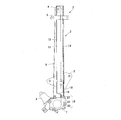
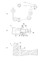
- the front view of the window regulator of this invention It is a figure of a guide rail, (a) enlarged front view, (b) AA enlarged sectional view, (c) BB enlarged sectional view. It is a figure of a housing, (a) An enlarged front view, (b) An enlarged plan view, (c) CC expanded sectional view. The principal part expanded sectional view explaining the assembly
- a window regulator 1 of the present invention is used by being fixed to an inner panel of a vehicle door (not shown).
- a glass holder (not shown) to which a window glass (not shown) is fixed.
- the carrier plate 2 Is fixed to the carrier plate 2, the guide rail 3 that guides the carrier plate 2 up and down, the wire guide 4 that is attached near the upper end of the guide rail 3, and the guide rail 3 that is a predetermined distance below the wire guide 4.
- a bracket 5 that is attached and used to fix the door to the inner panel, a housing 6 that is attached to the lower end of the guide rail 3, a drum 7 that is accommodated in the housing 6, and a drum that is attached to the housing 6 7 and a drive unit 8 that rotates 7.
- the raising wire 9 is wound around the wire guide 4, one end is connected to the carrier plate 2, and the other end is connected to the drum 7.
- the lowering wire 10 has one end connected to the carrier plate 2 and the other end connected to the drum 7.
- the drive unit 8 rotates the drum 7 to wind the ascending wire 9 around the drum 7 and the descending wire 10 is arranged at one end side from the drum 7 by adopting the above configuration.
- the window regulator 1 of the present invention lowers the window glass by feeding the ascending wire 9 to one end side from the drum 7 and winding the descending wire 10 around the drum 7.
- the window regulator 1 is characterized by the configuration of the guide rail 3 and the housing 6, and other known configurations can be adopted. Therefore, in the following, the description will focus on the configuration of the guide rail 3 and the housing 6.
- the guide rail 3 is formed by forming a thin metal plate such as a substantially rectangular galvanized steel plate having a predetermined length in the vertical direction into a predetermined shape.
- the guide rail 3 includes a rail main body portion 11 that extends vertically and an insertion portion 12 that is provided at the lower end of the rail main body portion 11 and passes through the housing 6 shown in FIG. 3.
- the guide rail 3 is formed at a bent portion 13 that is bent at a substantially right angle to the edge of one end in the width direction, and is formed on the inner side by a predetermined length from the other end in the width direction.
- a double bent portion 14 protruding in the opposite direction is formed.
- the rail body 11 is provided in the vicinity of the upper end, and is provided with a through hole 15 for rotatably mounting the wire guide 4 shown in FIG. 1, and is provided in the vicinity of the lower end to lock the housing 6 shown in FIG. 3. And a piece 16.
- the upper edge of the locking piece 16 is connected to the rail main body 11 and has a predetermined width in the width direction of the rail main body 11.
- the lower end direction of the rail main body 11 It is a rectangular plate extending in the direction.
- the locking piece 16 is formed integrally with the rail body 11 by punching out the rail body 11.
- 2B and 2C the locking piece 16 is bent at a predetermined angle at the upper edge so that the lower edge protrudes in the same direction as the bent portion 13.
- the insertion part 12 is provided with a rectangular first insertion part 17 formed including the double bent part 14, and the first insertion part 17 and the notch part 18 between them.
- a rectangular second insertion portion 19 is provided that is positioned below the locking piece 16 and includes the bent portion 13.
- the first insertion portion 17 is formed narrower in the width direction of the guide rail 3 and longer in the longitudinal direction of the guide rail 3 than the second insertion portion 19.
- the housing 6 is made of a material such as resin, metal, etc., and as shown in FIG. 3, a main body portion in which a drum housing portion (not shown) for rotatably accommodating the drum 7 shown in FIG. 1 is formed. 20 and a protruding portion 21 protruding from the upper surface of the main body portion 20.
- the protrusion 21 sequentially stores the first insertion portion 17 shown in FIG. 2A from the vicinity of the right end of the upper surface toward the left end.
- the second part 22 communicates with the drum housing part (not shown) and accommodates the lower wire guide groove 23 for inserting the lower wire 10 shown in FIG. 1 and the second insertion part 19 shown in FIG.
- the ascending wire guide groove 25 that communicates with the accommodating portion 24 and the drum accommodating portion and through which the ascending wire 9 shown in FIG. 1 is inserted is formed so as to open upward.
- the first accommodating portion 22 and the second accommodating portion 24 constitute an accommodating portion 26 and allow the first insertion portion 17 and the second insertion portion 19 to move in the longitudinal direction of the guide rail 3.
- the first insertion part 17 and the second insertion part 19 are restricted from moving in the direction perpendicular to the longitudinal direction of the guide rail 3.
- the protruding portion 21 includes a protruding plate 27 erected upward from the upper surface on the front side of the second accommodating portion 24 (FIGS. 3A and 3B). reference).
- the protruding portion 21 constitutes an engaging portion 28 that is coupled to the distal end of the locking piece 16 shown in FIG. 2 by the vicinity of the corner where the rear side surface of the protruding plate 27 and the upper surface of the protruding portion 21 are joined.
- the protruding portion 21 is formed on the upper surface between the second accommodating portion 24 and the protruding plate 27 by forming an inclined surface inclined downward from the second accommodating portion 24 side toward the engaging portion 28.
- tip of 16 to the engaging part 28 is comprised.
- the guide portion 29 is not limited to the inclined surface as long as the leading end of the locking piece 16 can be guided to the engaging portion 28.
- the assembly of the guide rail 3 and the housing 6 that are configured as described above will be described. This assembly is performed by inserting the first insertion portion 17 and the second insertion portion 19 of the insertion portion 12 of the guide rail 3 into the first accommodation portion 22 and the second accommodation portion 24 of the accommodation portion 26 of the housing 6, respectively. As shown in FIG. 4A, the guide rail 3 is moved downward relative to the housing 6 (arrow i). At this time, if the bending angle at the upper edge of the locking piece 16 formed on the rail body 11 of the guide rail 3 is appropriate, the tip of the locking piece 16 is engaged with the engaging portion 28 of the housing 6. Match.
- the locking piece 16 extends toward the lower end of the rail body 11, that is, toward the housing 6.
- the locking piece 16 is formed in a wide width, and when the tip engages with the engaging portion 28 of the housing 6 as shown in FIG. 3 has a rigidity that can stably regulate the movement in the upward direction of the longitudinal direction, that is, the direction of decreasing the tension of the ascending wire 9 and the descending wire 10 shown in FIG. Therefore, by engaging the tip of the locking piece 16 with the engaging portion 28, the housing 6 is restricted from moving in the direction in which the tension of the ascending wire 9 and the descending wire 10 is reduced.
- the window regulator 1 of the present invention it is provided on the rail body 11 of the guide rail 3 that guides the carrier plate 2 to which the glass holder (not shown) to which the window glass is fixed is fixed, and is formed wide.
- the engagement end 28 provided on the housing 6 that accommodates the drum 7 connected to the other ends of the ascending wire 9 and the descending wire 10 is engaged with the distal end of the locking piece 16 whose rigidity has been improved. To do.
- the housing 6 moves to the direction which reduces the tension
- the locking piece 16 is formed by a portion of the guide rail 3 where the rail main body 11 is bent. Therefore, it is necessary to form the locking piece 16 with a separate member from the rail main body 11. It is easier to manufacture.
- the window regulator 1 of the present invention includes a guide portion 29 that is an inclined surface in which the housing 6 is inclined toward the engaging portion 28. For this reason, in the present window regulator 1, even when the bending angle at the upper edge of the locking piece 16 is insufficient and the leading end of the locking piece 16 does not engage with the engaging portion 28, the guide portion 29 is engaged. The front end of the locking piece 16 is guided to the engaging portion 28 while sliding the front end of the stop piece 16. As a result, the window regulator 1 reliably engages the distal end of the locking piece 16 with the engaging portion 28 without any additional work, so that the housing 6 has the tension of the ascending wire 9 and the descending wire 10. It is possible to restrict the movement in the direction of decreasing. Therefore, the window regulator 1 is easy to manufacture and can reliably apply tension to the ascending wire 9 and the descending wire 10. Further, the tension of the ascending wire 9 and the descending wire 10 can be stabilized.
- window regulator 1 shown in the present embodiment is only one aspect of the window regulator according to the present invention, and various modifications can be made without departing from the gist of the present invention.
- the window regulator according to the present invention can be applied to a vehicle door.
Landscapes
- Window Of Vehicle (AREA)
Abstract
Description
2 キャリアプレート
3 ガイドレール
4 ワイヤガイド
6 ハウジング
7 ドラム
8 駆動部
9 上昇用ワイヤ
10 下降用ワイヤ
11 レール本体部
12 挿通部
16 係止片
26 収容部
28 係合部
29 案内部
Claims (4)
- 窓ガラスが固定されるキャリアプレートと、
該キャリアプレートの移動をガイドするガイドレールと、
該ガイドレールの一端に設けられるハウジングと、
前記ガイドレールの他端に設けられるワイヤガイドと、
前記ハウジングに収容されるドラムと、
前記ワイヤガイドに掛け回され、一端が前記キャリアプレートに、他端が前記ドラムに連結された上昇用ワイヤと、
一端が前記キャリアプレートに、他端が前記ドラムに連結された下降用ワイヤと、
前記ドラムを回転駆動する駆動部とを備えたウインドレギュレータにおいて、
前記ガイドレールは、レール本体部と、前記レール本体部の一端に設けられ、前記ハウジングへ挿通される挿通部と、前記レール本体部に設けられた係止片とを有し、
前記ハウジングは、前記挿通部を収容する収容部と、前記係止片の先端と係合する係合部と、前記係止片の先端と当接したときに前記係止片の先端を前記係合部まで案内する案内部とを有し、
前記係止片と前記係合部とが係合することで、前記ハウジングが前記上昇用ワイヤおよび前記下降用ワイヤの張力を減少させる方向へ移動するのを規制することを特徴とするウインドレギュレータ。 - 前記係止片は、前記レール本体部から突出するように折り曲げられている部分であることを特徴とする請求項1記載のウインドレギュレータ。
- 前記案内部は、前記係止片を前記係合部まで案内するにしたがって、前記レール本体部からの前記係止片の折り曲げ角度を増加させるように、前記係合部に向かって傾斜していることを特徴とする請求項2記載のウインドレギュレータ。
- 前記係止片は、前記ハウジングに向かって延び、幅広に形成されていることを特徴とする請求項2または3記載のウインドレギュレータ。
Priority Applications (3)
| Application Number | Priority Date | Filing Date | Title |
|---|---|---|---|
| CN201280026224.9A CN103582735B (zh) | 2011-05-31 | 2012-05-31 | 玻璃升降器 |
| US14/122,670 US9222295B2 (en) | 2011-05-31 | 2012-05-31 | Window regulator |
| JP2013518148A JP5925198B2 (ja) | 2011-05-31 | 2012-05-31 | ウインドレギュレータ |
Applications Claiming Priority (2)
| Application Number | Priority Date | Filing Date | Title |
|---|---|---|---|
| JP2011121144 | 2011-05-31 | ||
| JP2011-121144 | 2011-05-31 |
Publications (1)
| Publication Number | Publication Date |
|---|---|
| WO2012165527A1 true WO2012165527A1 (ja) | 2012-12-06 |
Family
ID=47259379
Family Applications (1)
| Application Number | Title | Priority Date | Filing Date |
|---|---|---|---|
| PCT/JP2012/064032 Ceased WO2012165527A1 (ja) | 2011-05-31 | 2012-05-31 | ウインドレギュレータ |
Country Status (4)
| Country | Link |
|---|---|
| US (1) | US9222295B2 (ja) |
| JP (1) | JP5925198B2 (ja) |
| CN (1) | CN103582735B (ja) |
| WO (1) | WO2012165527A1 (ja) |
Cited By (1)
| Publication number | Priority date | Publication date | Assignee | Title |
|---|---|---|---|---|
| CN103411496A (zh) * | 2013-05-29 | 2013-11-27 | 湖南吉利汽车部件有限公司 | 一种交叉臂式车门玻璃升降器检测装置及检测方法 |
Families Citing this family (5)
| Publication number | Priority date | Publication date | Assignee | Title |
|---|---|---|---|---|
| JP5944882B2 (ja) * | 2013-12-17 | 2016-07-05 | シロキ工業株式会社 | ウインドレギュレータ及びウインドレギュレータの製造方法 |
| JP2016204944A (ja) * | 2015-04-21 | 2016-12-08 | 株式会社ハイレックスコーポレーション | ウインドレギュレータ |
| JP6723826B2 (ja) * | 2016-05-24 | 2020-07-15 | シロキ工業株式会社 | ワイヤ式ウインドレギュレータ |
| KR20190028084A (ko) * | 2017-09-08 | 2019-03-18 | 현대자동차주식회사 | 비모듈형 듀얼 레귤레이터 어셈블리 |
| JP6715873B2 (ja) * | 2018-02-22 | 2020-07-01 | 株式会社城南製作所 | ウインドレギュレータ |
Citations (2)
| Publication number | Priority date | Publication date | Assignee | Title |
|---|---|---|---|---|
| JPH01131785U (ja) * | 1988-02-29 | 1989-09-07 | ||
| JP4637522B2 (ja) * | 2004-07-20 | 2011-02-23 | 株式会社ハイレックスコーポレーション | ケーブル式のウインドレギュレータ |
Family Cites Families (12)
| Publication number | Priority date | Publication date | Assignee | Title |
|---|---|---|---|---|
| US4502247A (en) * | 1982-02-23 | 1985-03-05 | Nippon Cable System Inc. | Guide rail for a window regulator and slide guide mechanism employing the same |
| US4550529A (en) * | 1984-10-24 | 1985-11-05 | General Motors Corporation | Window stabilizing mechanism |
| US5079871A (en) * | 1991-04-26 | 1992-01-14 | General Motors Corporation | Twist lock window regulator pivot pin |
| JP2919769B2 (ja) | 1995-03-30 | 1999-07-19 | 株式会社大井製作所 | 窓ガラスの昇降装置およびその製造方法 |
| JP3332803B2 (ja) * | 1997-05-19 | 2002-10-07 | アイシン精機株式会社 | ドアガラスの昇降装置 |
| US5884434A (en) * | 1998-06-12 | 1999-03-23 | General Motors Corporation | Door handle to latch rod connection |
| JP2000356068A (ja) | 1999-06-16 | 2000-12-26 | Ansei:Kk | ドアガラス昇降装置 |
| WO2002075090A1 (en) * | 2001-03-19 | 2002-09-26 | Nippon Cable System Inc. | Curved glass support structure and wind regulator |
| US6758013B2 (en) * | 2002-01-25 | 2004-07-06 | Delphi Technologies, Inc. | Integrated roller cable assembly |
| FR2886966B1 (fr) * | 2005-06-10 | 2008-11-28 | Peugeot Citroen Automobiles Sa | Leve-vitre pour vehicule automobile |
| US20080005971A1 (en) * | 2006-06-21 | 2008-01-10 | Dickie Robert Boyer | Single Rail No Pulley Window Regulator |
| JP5507042B2 (ja) * | 2007-08-10 | 2014-05-28 | 株式会社ミツバ | 車両用窓開閉装置 |
-
2012
- 2012-05-31 JP JP2013518148A patent/JP5925198B2/ja active Active
- 2012-05-31 CN CN201280026224.9A patent/CN103582735B/zh active Active
- 2012-05-31 US US14/122,670 patent/US9222295B2/en active Active
- 2012-05-31 WO PCT/JP2012/064032 patent/WO2012165527A1/ja not_active Ceased
Patent Citations (2)
| Publication number | Priority date | Publication date | Assignee | Title |
|---|---|---|---|---|
| JPH01131785U (ja) * | 1988-02-29 | 1989-09-07 | ||
| JP4637522B2 (ja) * | 2004-07-20 | 2011-02-23 | 株式会社ハイレックスコーポレーション | ケーブル式のウインドレギュレータ |
Cited By (1)
| Publication number | Priority date | Publication date | Assignee | Title |
|---|---|---|---|---|
| CN103411496A (zh) * | 2013-05-29 | 2013-11-27 | 湖南吉利汽车部件有限公司 | 一种交叉臂式车门玻璃升降器检测装置及检测方法 |
Also Published As
| Publication number | Publication date |
|---|---|
| JPWO2012165527A1 (ja) | 2015-02-23 |
| CN103582735B (zh) | 2016-09-28 |
| US20140109481A1 (en) | 2014-04-24 |
| JP5925198B2 (ja) | 2016-05-25 |
| US9222295B2 (en) | 2015-12-29 |
| CN103582735A (zh) | 2014-02-12 |
Similar Documents
| Publication | Publication Date | Title |
|---|---|---|
| JP5925198B2 (ja) | ウインドレギュレータ | |
| JPWO2013062060A1 (ja) | ウインドレギュレータ | |
| US10017979B2 (en) | Window regulator and method of producing window regulator | |
| JP6954956B2 (ja) | 対象物移動装置 | |
| JP5563263B2 (ja) | キャリアプレートとウインドガラスの取付構造およびそれを用いたウインドレギュレータ | |
| JP5714839B2 (ja) | ウインドレギュレータ | |
| JP2017210757A (ja) | ワイヤ式ウインドレギュレータ | |
| JP6985892B2 (ja) | ウインドレギュレータ | |
| JP6247227B2 (ja) | 開閉体開閉装置 | |
| US20130133265A1 (en) | Window regulator | |
| JP2011069059A (ja) | ワイヤドラム式のウインドウレギュレータ | |
| CN101908698B (zh) | 具有杆件的线束组件 | |
| KR102053883B1 (ko) | 윈도우 레귤레이터의 승강부재 | |
| JP6989353B2 (ja) | ウインドレギュレータ | |
| JP2017002673A (ja) | 対象物移動装置 | |
| JP7315521B2 (ja) | キャリアプレート及び対象物移動装置 | |
| JP6175332B2 (ja) | ワイヤ式ウインドウレギュレータ | |
| JP2013011139A (ja) | ウインドレギュレータ | |
| JP2012092574A (ja) | ウインドレギュレータ | |
| CN105102748B (zh) | 具备线缆张力增强机构的窗户调节器 | |
| WO2012011593A1 (ja) | ウインドウレギュレータ | |
| WO2014163103A1 (ja) | ウインドレギュレータ | |
| JP2008252993A (ja) | 給電箱 | |
| WO2016136890A1 (ja) | 駆動力の伝達機構及びウインドレギュレータ | |
| JP2022080036A (ja) | 引手部材 |
Legal Events
| Date | Code | Title | Description |
|---|---|---|---|
| 121 | Ep: the epo has been informed by wipo that ep was designated in this application |
Ref document number: 12792353 Country of ref document: EP Kind code of ref document: A1 |
|
| WWE | Wipo information: entry into national phase |
Ref document number: 14122670 Country of ref document: US |
|
| NENP | Non-entry into the national phase |
Ref country code: DE |
|
| ENP | Entry into the national phase |
Ref document number: 2013518148 Country of ref document: JP Kind code of ref document: A |
|
| 122 | Ep: pct application non-entry in european phase |
Ref document number: 12792353 Country of ref document: EP Kind code of ref document: A1 |