WO2012161194A1 - 輸液ポンプ - Google Patents
輸液ポンプ Download PDFInfo
- Publication number
- WO2012161194A1 WO2012161194A1 PCT/JP2012/063079 JP2012063079W WO2012161194A1 WO 2012161194 A1 WO2012161194 A1 WO 2012161194A1 JP 2012063079 W JP2012063079 W JP 2012063079W WO 2012161194 A1 WO2012161194 A1 WO 2012161194A1
- Authority
- WO
- WIPO (PCT)
- Prior art keywords
- roller
- door
- infusion
- lock
- clamp
- Prior art date
Links
- 238000001802 infusion Methods 0.000 title claims abstract description 564
- 230000007246 mechanism Effects 0.000 claims abstract description 200
- 238000001514 detection method Methods 0.000 claims description 48
- 230000033001 locomotion Effects 0.000 claims description 45
- 230000005540 biological transmission Effects 0.000 claims description 3
- 230000000903 blocking effect Effects 0.000 abstract description 4
- 238000003825 pressing Methods 0.000 description 132
- 238000011144 upstream manufacturing Methods 0.000 description 31
- 230000005856 abnormality Effects 0.000 description 29
- 210000000078 claw Anatomy 0.000 description 22
- 238000000034 method Methods 0.000 description 19
- 230000002572 peristaltic effect Effects 0.000 description 19
- 230000002093 peripheral effect Effects 0.000 description 16
- 238000010586 diagram Methods 0.000 description 14
- 230000008569 process Effects 0.000 description 11
- 230000002159 abnormal effect Effects 0.000 description 10
- 239000007924 injection Substances 0.000 description 8
- 238000002347 injection Methods 0.000 description 8
- 230000037452 priming Effects 0.000 description 8
- 239000000243 solution Substances 0.000 description 6
- 230000036541 health Effects 0.000 description 5
- 238000002360 preparation method Methods 0.000 description 4
- 239000000126 substance Substances 0.000 description 4
- 230000008859 change Effects 0.000 description 3
- 238000002474 experimental method Methods 0.000 description 3
- 230000005484 gravity Effects 0.000 description 3
- 230000010354 integration Effects 0.000 description 3
- 238000012423 maintenance Methods 0.000 description 3
- 230000000149 penetrating effect Effects 0.000 description 3
- 238000012545 processing Methods 0.000 description 3
- 239000005062 Polybutadiene Substances 0.000 description 2
- 230000008878 coupling Effects 0.000 description 2
- 238000010168 coupling process Methods 0.000 description 2
- 238000005859 coupling reaction Methods 0.000 description 2
- 230000001186 cumulative effect Effects 0.000 description 2
- 230000007423 decrease Effects 0.000 description 2
- 239000003978 infusion fluid Substances 0.000 description 2
- 230000007774 longterm Effects 0.000 description 2
- 239000000463 material Substances 0.000 description 2
- 229920002857 polybutadiene Polymers 0.000 description 2
- 229920000915 polyvinyl chloride Polymers 0.000 description 2
- 239000004800 polyvinyl chloride Substances 0.000 description 2
- 239000011347 resin Substances 0.000 description 2
- 229920005989 resin Polymers 0.000 description 2
- 230000004044 response Effects 0.000 description 2
- 230000006835 compression Effects 0.000 description 1
- 238000007906 compression Methods 0.000 description 1
- 239000000470 constituent Substances 0.000 description 1
- 239000003814 drug Substances 0.000 description 1
- 229940079593 drug Drugs 0.000 description 1
- 239000000284 extract Substances 0.000 description 1
- 239000012530 fluid Substances 0.000 description 1
- 230000006872 improvement Effects 0.000 description 1
- 238000009434 installation Methods 0.000 description 1
- 239000004973 liquid crystal related substance Substances 0.000 description 1
- 230000036316 preload Effects 0.000 description 1
- 239000011435 rock Substances 0.000 description 1
Images


Classifications
-
- A—HUMAN NECESSITIES
- A61—MEDICAL OR VETERINARY SCIENCE; HYGIENE
- A61M—DEVICES FOR INTRODUCING MEDIA INTO, OR ONTO, THE BODY; DEVICES FOR TRANSDUCING BODY MEDIA OR FOR TAKING MEDIA FROM THE BODY; DEVICES FOR PRODUCING OR ENDING SLEEP OR STUPOR
- A61M5/00—Devices for bringing media into the body in a subcutaneous, intra-vascular or intramuscular way; Accessories therefor, e.g. filling or cleaning devices, arm-rests
- A61M5/14—Infusion devices, e.g. infusing by gravity; Blood infusion; Accessories therefor
- A61M5/168—Means for controlling media flow to the body or for metering media to the body, e.g. drip meters, counters ; Monitoring media flow to the body
- A61M5/16804—Flow controllers
- A61M5/16813—Flow controllers by controlling the degree of opening of the flow line
-
- F—MECHANICAL ENGINEERING; LIGHTING; HEATING; WEAPONS; BLASTING
- F04—POSITIVE - DISPLACEMENT MACHINES FOR LIQUIDS; PUMPS FOR LIQUIDS OR ELASTIC FLUIDS
- F04B—POSITIVE-DISPLACEMENT MACHINES FOR LIQUIDS; PUMPS
- F04B43/00—Machines, pumps, or pumping installations having flexible working members
- F04B43/0009—Special features
- F04B43/0081—Special features systems, control, safety measures
-
- A—HUMAN NECESSITIES
- A61—MEDICAL OR VETERINARY SCIENCE; HYGIENE
- A61M—DEVICES FOR INTRODUCING MEDIA INTO, OR ONTO, THE BODY; DEVICES FOR TRANSDUCING BODY MEDIA OR FOR TAKING MEDIA FROM THE BODY; DEVICES FOR PRODUCING OR ENDING SLEEP OR STUPOR
- A61M39/00—Tubes, tube connectors, tube couplings, valves, access sites or the like, specially adapted for medical use
- A61M39/22—Valves or arrangement of valves
- A61M39/28—Clamping means for squeezing flexible tubes, e.g. roller clamps
- A61M39/281—Automatic tube cut-off devices, e.g. squeezing tube on detection of air
-
- A—HUMAN NECESSITIES
- A61—MEDICAL OR VETERINARY SCIENCE; HYGIENE
- A61M—DEVICES FOR INTRODUCING MEDIA INTO, OR ONTO, THE BODY; DEVICES FOR TRANSDUCING BODY MEDIA OR FOR TAKING MEDIA FROM THE BODY; DEVICES FOR PRODUCING OR ENDING SLEEP OR STUPOR
- A61M39/00—Tubes, tube connectors, tube couplings, valves, access sites or the like, specially adapted for medical use
- A61M39/22—Valves or arrangement of valves
- A61M39/28—Clamping means for squeezing flexible tubes, e.g. roller clamps
- A61M39/285—Cam clamps, e.g. roller clamps with eccentric axis
-
- A—HUMAN NECESSITIES
- A61—MEDICAL OR VETERINARY SCIENCE; HYGIENE
- A61M—DEVICES FOR INTRODUCING MEDIA INTO, OR ONTO, THE BODY; DEVICES FOR TRANSDUCING BODY MEDIA OR FOR TAKING MEDIA FROM THE BODY; DEVICES FOR PRODUCING OR ENDING SLEEP OR STUPOR
- A61M5/00—Devices for bringing media into the body in a subcutaneous, intra-vascular or intramuscular way; Accessories therefor, e.g. filling or cleaning devices, arm-rests
- A61M5/14—Infusion devices, e.g. infusing by gravity; Blood infusion; Accessories therefor
- A61M5/142—Pressure infusion, e.g. using pumps
- A61M5/14212—Pumping with an aspiration and an expulsion action
- A61M5/14228—Pumping with an aspiration and an expulsion action with linear peristaltic action, i.e. comprising at least three pressurising members or a helical member
-
- F—MECHANICAL ENGINEERING; LIGHTING; HEATING; WEAPONS; BLASTING
- F04—POSITIVE - DISPLACEMENT MACHINES FOR LIQUIDS; PUMPS FOR LIQUIDS OR ELASTIC FLUIDS
- F04B—POSITIVE-DISPLACEMENT MACHINES FOR LIQUIDS; PUMPS
- F04B43/00—Machines, pumps, or pumping installations having flexible working members
- F04B43/08—Machines, pumps, or pumping installations having flexible working members having tubular flexible members
- F04B43/082—Machines, pumps, or pumping installations having flexible working members having tubular flexible members the tubular flexible member being pressed against a wall by a number of elements, each having an alternating movement in a direction perpendicular to the axes of the tubular member and each having its own driving mechanism
-
- F—MECHANICAL ENGINEERING; LIGHTING; HEATING; WEAPONS; BLASTING
- F04—POSITIVE - DISPLACEMENT MACHINES FOR LIQUIDS; PUMPS FOR LIQUIDS OR ELASTIC FLUIDS
- F04B—POSITIVE-DISPLACEMENT MACHINES FOR LIQUIDS; PUMPS
- F04B43/00—Machines, pumps, or pumping installations having flexible working members
- F04B43/12—Machines, pumps, or pumping installations having flexible working members having peristaltic action
- F04B43/1223—Machines, pumps, or pumping installations having flexible working members having peristaltic action the actuating elements, e.g. rollers, moving in a straight line during squeezing
-
- F—MECHANICAL ENGINEERING; LIGHTING; HEATING; WEAPONS; BLASTING
- F04—POSITIVE - DISPLACEMENT MACHINES FOR LIQUIDS; PUMPS FOR LIQUIDS OR ELASTIC FLUIDS
- F04B—POSITIVE-DISPLACEMENT MACHINES FOR LIQUIDS; PUMPS
- F04B49/00—Control, e.g. of pump delivery, or pump pressure of, or safety measures for, machines, pumps, or pumping installations, not otherwise provided for, or of interest apart from, groups F04B1/00 - F04B47/00
- F04B49/10—Other safety measures
-
- A—HUMAN NECESSITIES
- A61—MEDICAL OR VETERINARY SCIENCE; HYGIENE
- A61M—DEVICES FOR INTRODUCING MEDIA INTO, OR ONTO, THE BODY; DEVICES FOR TRANSDUCING BODY MEDIA OR FOR TAKING MEDIA FROM THE BODY; DEVICES FOR PRODUCING OR ENDING SLEEP OR STUPOR
- A61M2205/00—General characteristics of the apparatus
- A61M2205/14—Detection of the presence or absence of a tube, a connector or a container in an apparatus
-
- A—HUMAN NECESSITIES
- A61—MEDICAL OR VETERINARY SCIENCE; HYGIENE
- A61M—DEVICES FOR INTRODUCING MEDIA INTO, OR ONTO, THE BODY; DEVICES FOR TRANSDUCING BODY MEDIA OR FOR TAKING MEDIA FROM THE BODY; DEVICES FOR PRODUCING OR ENDING SLEEP OR STUPOR
- A61M39/00—Tubes, tube connectors, tube couplings, valves, access sites or the like, specially adapted for medical use
- A61M39/22—Valves or arrangement of valves
- A61M39/28—Clamping means for squeezing flexible tubes, e.g. roller clamps
- A61M39/286—Wedge clamps, e.g. roller clamps with inclined guides
Definitions
- the present invention relates to an infusion pump.
- infusion pumps used when injecting medical chemicals into the body include various infusion pumps such as mechanical infusion pumps, gravity-driven infusion pumps using gravity, and preload infusion pumps. Are known.
- Peristaltic infusion pumps include a roller infusion pump that performs infusion by pressing an infusion tube with a rotor or the like provided with a roller, and a finger type infusion pump.
- the finger-type infusion pump is provided, for example, on a plurality of fingers arranged in one direction (a direction along the infusion tube), a cam for individually driving the fingers forward and backward, and a door side of the pump.
- the infusion tube connected to the infusion bag is connected to the infusion bag with the plurality of fingers and the pressure plate.
- each finger is individually driven forward and backward by a cam, and the infusion tube is sequentially pressed by each finger to send out the infusion by peristaltic motion (for example, patent Reference 1 and Patent Document 2).
- an infusion set used for infusion is generally an infusion tube connected to an infusion bag, a drip tube provided in the middle of the infusion tube, a roller clamp, and an injection needle connected to the tip of the infusion tube.
- the infusion tube of such an infusion set is attached to an infusion pump, the infusion tube is first closed with a roller clamp.
- the infusion tube is attached to the pump body (pump mechanism) with the door of the infusion pump open, and then the door of the infusion pump is closed. At this time (when the door is closed), at least one portion of the infusion tube is closed by the pump mechanism of the infusion pump.
- the roller clamp is opened, and then the infusion pump is driven to perform a predetermined infusion.
- the infusion tube is closed with a roller clamp after the infusion pump is stopped, and in this state (a state in which free flow is prevented), the infusion pump door is opened and the infusion tube is removed.
- Patent Document 3 and Patent Document 4 disclose a technique using a dedicated clamp having an anti-free flow function.
- the present invention has been made in consideration of such a situation, and an object thereof is to provide an infusion pump capable of reliably preventing free flow.
- the present invention provides a pump body having a pump mechanism that presses an infusion tube to feed the infusion in the infusion tube in one direction, a door that covers the infusion tube mounting position of the pump body in an openable and closable manner, and the door.
- An infusion pump provided with a door lock mechanism for locking in a closed state is premised, and in such an infusion pump, a roller clamp for closing or opening the infusion tube by moving a roller is held in the pump body. And a roller moving means for moving a roller of the roller clamp held by the clamp holding portion.
- the roller moving means is arranged in conjunction with the operation of the door lock mechanism, and when the door lock mechanism is in a locked state, the roller clamp roller is disposed at a position where the infusion tube is opened, and the door lock When the mechanism is in an unlocked state, the roller clamp roller is disposed at a position to close the infusion tube.
- the pump body is configured to hold the roller clamp
- the roller moving means for moving the roller clamp roller in conjunction with the operation of the door lock mechanism is provided, and the door lock mechanism is in an unlocked state.
- the roller clamp roller is placed in a position to close the infusion tube, so even if the infusion pump door is closed, the infusion tube is blocked by the roller clamp unless the door is locked. State is maintained. As a result, it is possible to reliably prevent a free flow due to incomplete closing of the door or forgetting to lock the door.
- the infusion tube is closed by the roller clamp accordingly, so that even if the door is accidentally opened during infusion, free flow occurs. None will happen.
- the door lock mechanism is operated to the unlocked state before opening the door after the infusion is completed, the infusion tube is surely closed by the roller clamp. The problem of "removing from” is also eliminated.
- the roller moving means moves the roller clamp roller held by the clamp holding portion to an open position for opening the infusion tube and a closing position for closing the infusion tube.
- a rack and pinion mechanism an actuator (electric motor) that drives the moving mechanism, a lock detection sensor that detects whether or not the door lock mechanism is in the lock position, and a control unit. Then, the control unit drives and controls the actuator based on the detection result of the lock detection sensor, and when the door lock mechanism is at the lock position, the roller clamp roller is arranged at a position to open the infusion tube, and the door lock When the mechanism is not in the locked position, a configuration in which the roller clamp roller is disposed at a position to close the infusion tube.
- the door lock mechanism is configured to bring the door into a locked state or an unlocked state by a rotation operation of the lock lever
- the roller moving means includes the lock lever.
- An operation force transmission mechanism (for example, a lock piece and a rack gear having an arc-shaped gear) that converts the rotational operation force into a force that moves the roller of the roller clamp held by the clamp holding portion and transmits the force is provided, and the door
- the lock lever of the lock mechanism is operated to the locked position, place the roller clamp roller in the position to open the infusion tube, and when the door lock mechanism lock lever is operated to the unlocked position.
- the present invention also includes a pump body having a pump mechanism that presses the infusion tube to feed the infusion in the infusion tube in one direction, and a door that covers the infusion tube mounting position of the pump body in an openable and closable manner.
- the pump body is provided with a clamp holding portion for holding a roller clamp that closes or opens the infusion tube by movement of the roller, the roller holding the roller clamp in the clamp holding portion, and the door
- the door lock mechanism for locking the door to the closed state is configured such that a part of the roller of the roller clamp is exposed to the outside through the opening (roller through hole) of the door in the closed state. I have.
- the door lock mechanism includes a lock piece and an engagement member that can be engaged with each other, and the roller of the roller clamp held by the clamp holding portion is in a tube open position when the door is closed.
- the lock piece and the engaging member are engaged to lock the door in the closed state, and the roller clamp is held in the clamp holding portion in the closed state.
- the engagement between the lock piece and the engagement member is released, and the door is unlocked.
- the infusion pump of this invention when the door is in the closed state (locked state), the lock piece of the door lock mechanism and the engaging member are engaged unless the roller clamp roller is operated to the tube closed position. (The locked state) is maintained. Thereby, even if it tries to open a door accidentally during infusion, since a door cannot be opened, the free flow by incorrect operation can be prevented. Further, after the infusion is completed, the door cannot be opened even if the door is opened before the infusion tube is closed by the roller clamp. This eliminates the problem of removing the infusion tube from the infusion pump in a state where the roller clamp has been forgotten to close (a situation where free flow can occur).
- the infusion pump of the present invention it is possible to reliably prevent free flow caused by an operation error or the like of a medical staff such as a nurse.
- the door has a lock lever that is rotatable about a fulcrum shaft, and the lock piece is provided on one end side of the lock lever, and the other end side.
- an operating piece that can contact the roller of the roller clamp held by the clamp holding portion is provided, and the lock lever is urged toward a lock position where the lock piece and the engaging member are engaged.
- a lock spring is provided, and when the operating piece of the lock lever is in a free state, the lock piece is arranged at a lock position where the lock piece and the engaging member are engaged by the elastic force of the lock spring.
- the lock piece of the lock lever when the door is open, the lock piece of the lock lever is in the lock position by the elastic force of the lock spring, so when the roller clamp is held in the clamp holding portion, the roller If the clamp roller is not in the tube closing position, the door cannot be closed because the lock piece and the engaging member interfere even if the door is to be closed (see, for example, FIG. 41).
- the lock piece when the door is in the closed state (locked state), the lock piece is arranged at the lock position by the elastic force of the lock spring unless the roller clamp roller is operated to the tube closed position. Since the engagement state (lock state) between the lock piece and the engagement member is maintained, the door cannot be opened. Thereby, the free flow by accidentally opening a door during infusion can be prevented. Even in the infusion pump of this configuration, after the infusion is completed, the door exposed to the outside of the door is rotated and the infusion tube is closed by the roller clamp, so that the door is unlocked and the door is closed. Can be opened.
- FIG. 2 shows a state in which the door of the infusion pump is opened. It is a figure which shows the state which operated the lock lever to the lock side in the door shown in FIG.
- FIG. 4 is a view taken in the direction of arrow X in FIG.
- FIG. 5 shows a state where the door of the infusion pump is opened, and shows a state where a roller clamp is held on the pump body.
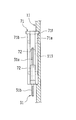
- FIG. 6 is a cross-sectional view taken along the line II in FIG. 5.
- FIG. 6 shows a cross section of only the holding portion of the roller clamp.
- FIG. 7 shows a state in which the door of the infusion pump is closed from the state of FIG. In FIG. 7, the door is not shown.
- FIG. 8 shows a cross section of only the holding portion of the roller clamp.
- FIG. 13 is a cross-sectional view of each finger cut along a plane orthogonal to the cam shaft. It is operation
- FIG. 17 shows a state in which the door of the infusion pump is opened. It is a figure which shows the state which operated the lock lever to the lock side in the door shown in FIG. It is a Y arrow line view of FIG. It is a schematic block diagram which shows another example of the infusion pump of this invention.
- FIG. 17 shows a state in which the door of the infusion pump is opened. It is a figure which shows the state which operated the lock lever to the lock side in the door shown in FIG. It is a Y arrow line view of FIG. It is a schematic block diagram which shows another example of the infusion pump of this invention.
- FIG. 20 shows a state where the door of the infusion pump is opened, and shows a state where a roller clamp is held on the pump body.
- FIG. 22 shows a state in which the door of the infusion pump is closed from the state of FIG. In addition, illustration of the door is abbreviate
- It is a perspective view of the roller slider of a roller moving mechanism. It is operation
- FIG. 32 shows a state where the door of the infusion pump is opened.
- FIG. 33 is a view on arrow M in FIG. 32.
- FIG. 33 is a perspective view which extracts and shows the lock lever etc. which are applied to the infusion pump of FIG.
- FIG. 32 shows a perspective view of a roller clamp.
- FIG. 35 shows a state where the door of the infusion pump is opened, and also shows a state where a roller clamp is held on the pump body.
- FIG. 36 shows a state in which the door of the infusion pump is closed from the state of FIG. In FIG. 36, the door is not shown.
- FIG. 37 shows a state in which the door is locked by rotating the roller of the roller clamp from the state of FIG. In FIG. 37, the door is not shown.
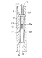
- FIG. 38 is a VV cross-sectional view of FIG. 37.
- FIG. 38 is a sectional view taken along line VI-VI in FIG. 37.
- FIG. 43 is a cross-sectional view of each finger cut along a plane orthogonal to the cam shaft. It is operation
- FIG. 51 shows a state in which the door of the infusion pump is opened. It is a figure which shows the state which operated the lock lever to the lock
- FIG. 53 is a view on arrow P in FIG. 52. It is a schematic block diagram which shows another example of an infusion pump.
- FIG. 54 shows a state in which the door of the infusion pump is closed.
- FIG. 54 the door is not shown.
- FIG. 56 is a cross-sectional view of each finger cut along a plane orthogonal to the cam shaft. It is operation
- FIG. 60 is a cross-sectional view taken along a plane orthogonal to the cam shaft of the pump mechanism. It is a schematic block diagram which shows another example of an infusion pump.
- FIG. 61 shows a state in which the door of the infusion pump is opened.
- An infusion set S shown in FIG. 27 includes an infusion bag B for storing a chemical solution, a connecting needle S1 inserted into a port Bp of the infusion bag B, an infusion tube S2 for visually confirming the flow rate of the infusion solution, and these connecting needles.
- An upstream infusion tube T connecting S1 and the infusion tube S2, a downstream infusion tube T connected to the infusion tube S2, a roller clamp 7 provided in the middle of the downstream infusion tube T, and an infusion An injection needle (venous needle) S3 connected to the tip of the tube T is used.
- the roller clamp 7 includes a clamp main body 71 and a roller 72 as shown in FIGS.
- the clamp body 71 is a resin molded product in which a pair of side walls 71a and 71b and a bottom plate 71c that are opposed to each other with a predetermined interval are integrally formed.
- Guide grooves 711a and 711b are provided on the inner surfaces of the side walls 71a and 71b to guide and support the rotation shafts 72a and 72b of the roller 72.
- a V-groove 71e is formed on the bottom surface 71d of the clamp body 71 (the top surface of the bottom plate 71c).
- the bottom surface 71d of the clamp body 71 is inclined with respect to the guide grooves 711a and 711b, and the guide grooves 711a and 711b and the bottom surface are gradually moved from one end side (flange 71f side) of the clamp body 71 to the other end side.
- the distance from 71d is configured to be small.
- the roller 72 rotates along the guide grooves 711a and 711b between one end (end on the flange 71f side) of the clamp body 71 and the other end (end opposite to the flange 71f).
- the roller 72 is positioned at the moving end (opening side moving end) on the flange 71f side, the distance between the outer peripheral surface of the roller 72 and the bottom surface 71d of the clamp body 71 is maximized.
- the roller 72 is positioned at the opposite moving end (closing side moving end), the distance between the outer peripheral surface of the roller 72 and the bottom surface 71d of the clamp body 71 is minimized.
- the infusion tube T is inserted between the bottom surface 71d of the clamp body 71 and the outer peripheral surface of the roller 72, and the roller 72 is rotated to close the roller 72.
- the infusion tube T is completely closed.
- the roller 72 is rotationally moved from this state toward the flange 71f side of the clamp body 71, the pressing amount (flat amount) to the infusion tube T is reduced with the rotational movement of the roller 72, and the infusion tube T
- the volume of infusion that can flow inside increases.
- the infusion tube T will be in the state (completely open state) which is not pressed by the roller 72.
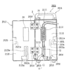
- the infusion pump 1 of this example is a peristaltic finger type infusion pump, and includes a pump body (casing) 11 and a door 12 that closes the front side (tube attachment position) of the pump body 11.
- the door 12 is swingably (rotatably) supported by the pump body 11 via hinges 14 and 14, and is opened from the position where the front side of the pump body 11 is completely closed (for example, 180 °). Oscillate until the position).
- a tube mounting guide portion 111 On the front surface of the pump body 11, a tube mounting guide portion 111, a pump portion 112 that is enlarged from the tube mounting guide portion 111 in a rectangular shape, and a clamp holding recess 113 are provided in order from the upstream side in the infusion feeding direction.
- the groove width of the tube mounting guide portion 111 is a size corresponding to the outer diameter of the infusion tube T of the infusion set described above.
- the tube mounting guide part 111 is formed in a shape (curved shape) curved in the lateral direction.
- a pressing plate 24 is provided on the inner surface of the door 12. The pressing plate 24 is disposed at a position facing the distal ends of the plurality of fingers 21... 21 of the pump mechanism 2 with the door 12 closed.
- the clamp holding recess 113 is formed in a shape capable of fitting one side wall 71a of the roller clamp 7 of the infusion set S described above.
- the infusion tube T is arranged along the vertical direction of the infusion pump 1, and the movement of the roller 72 in the vertical direction causes the infusion tube T to move. Blocking and opening can be performed.
- a clamp holding recess 123 is provided on the inner surface of the door 12 at a position corresponding to the clamp holding recess 113 on the front surface of the pump main body 11 (a position facing the door 12 when the door 12 is closed).
- the clamp holding recess 123 of the door 12 is formed in a shape capable of fitting the other side wall 71b of the roller clamp 7, as shown in FIGS. And the roller 72 of the roller clamp 7 hold
- a lever housing recess 11 a into which a lock lever 131 of a door lock mechanism 13 (to be described later) can enter is provided on the side of the pump body 11.
- a lock chamber 11b into which a lock piece 132 (to be described later) can enter is provided inside the lever housing recess 11a.
- a locking piece 134 on which the lock claw 133 of the lock piece 132 is hooked is provided at the upper part of the lock chamber 11b. In the vicinity of the locking piece 134, it is detected whether or not the door lock mechanism 13 is in the locked position.
- a lock detection sensor 6 is disposed.
- the lock detection sensor 6 is a known photoelectric sensor (reflective type) composed of a light emitting element and a light receiving element, and as shown in FIG. 7, a position where the lock claw 133 of the lock piece 132 engages with the locking piece 134.
- the lock detection signal (ON signal) is output only when the door 12 is in the closed position (when the door 12 is kept closed).
- a lock lever 131 is disposed at the side end of the door 12 (the end opposite to the hinge 14).
- the lock lever 131 is provided so as to be rotatable about the rotation shaft 131a.
- the lock lever 131 locks the door 12 from the unlock position (unlock position) shown in FIGS. 2 and 5 (FIGS. 3 and 7). Can be swung (for example, can be swung approximately 90 °).
- a lock piece 132 is integrally formed with the lock lever 131.
- a lock claw 133 is provided at the tip of the lock piece 132.
- the door 12 is held in a completely closed state.
- the lock lever 131, the lock piece 132, the lock claw 133, and the locking piece 134 of the pump body 11 constitute the door lock mechanism 13, and the door lock mechanism 13 is operated by operating the lock lever 131. Can be placed in the locked or unlocked position.
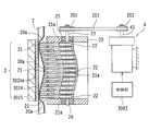
- the pump mechanism 2 has a plurality (13 in the example shown in FIG. 12) of fingers 21... 21 arranged along one direction (a direction along the infusion tube T attached to the pump body 11), and each of the fingers 21.
- fingers 21... 21 are configured by eccentric cams 22... 22 for individually moving forward and backward, a cam shaft 23 for rotating each eccentric cam 22, the pressing plate 24, the holding frame 20, and the like.
- Openings 20a... 20a are provided at positions corresponding to the fingers 21 on the front side of the holding frame 20, and the front ends of the fingers 21 pass through the openings 20a on the front side of the holding frame 20 (infusion tube T). To the side). Further, the movement of the plurality of fingers 21... 21 in the axial direction (axial direction of the cam shaft 23) is restricted by the holding frame 20.
- Each finger 21 is a plate-like member, and can be moved (moved forward and backward) individually while sliding on each other.
- Each cam 21 has a cam hole 21a.
- a disc-shaped eccentric cam 22 is fitted in each cam hole 21a.
- Each eccentric cam 22 is rotatable in the cam hole 21 a, and these eccentric cams 22... 22 are integrally attached to the cam shaft 23.
- each eccentric cam 22 The center of the disk of each eccentric cam 22 is eccentric with respect to the cam shaft 23, and as shown in FIG. 13, when the cam shaft 23 makes one rotation (360 ° rotation), the tip of the finger 21 moves forward most. It reciprocates once between the position (tube closed position) and the last retracted position (tube fully open position).
- the plurality of eccentric cams 22 are attached to the camshaft 23 with a predetermined phase difference (phase difference in the rotational direction of the camshaft 23). Specifically, the eccentric cams 22... 22 have a phase difference (360 ° / the number of the eccentric cams 22) such that the tips of the fingers 21. ) Is attached to the camshaft 23.
- FIG. 13 shows the position of the finger 21 every time the camshaft 23 rotates 90 °.
- the cam shaft 23 of the pump mechanism 2 is provided along the vertical direction (the arrangement direction of the plurality of fingers 21... 21).
- a lower end portion of the cam shaft 23 is rotatably supported by a bearing 26 provided on the holding frame 20.
- the upper portion of the cam shaft 23 protrudes upward through the wall body of the holding frame 20.
- a bearing 25 is provided at the penetrating portion of the cam shaft 23, and the upper portion of the cam shaft 23 is rotatably supported by the bearing 25.
- a timing pulley (driven pulley) 201 is attached to the upper end of the camshaft 23 so as to rotate together.
- a timing belt 203 is wound between the timing pulley 201 of the cam shaft 23 and a timing pulley (driving pulley) 202 attached integrally to the rotating shaft 41 of an electric motor (for example, a stepping motor) 4.
- the cam shaft 23 is rotated by driving the electric motor 4.
- the electric motor 4 is driven and controlled (rotational speed control) by the controller 5.
- the electric motor 4 is supplied with electric power from a battery built in the infusion pump 1 or a commercial power source.
- each eccentric cam 22 is rotated in the cam hole 21 a of the finger 21.
- each finger 21 advances / retreats sequentially from the upstream side (upstream side in the infusion feeding direction) to the downstream side.
- the tip of the finger 21 moves in a peristaltic wave shape from the upstream side to the downstream side.
- a peristaltic motion is imparted to the infusion tube T disposed between the distal ends of the fingers 21.
- the infusion in T is sent out from the upstream side to the downstream side.
- a buffer sheet 24 a is provided between the pressing plate 24 and the base plate 15 in order to reduce the overload that the infusion tube T receives from the fingers 21.
- the control unit 5 is mainly composed of a microcomputer or the like.
- the controller 5 controls the electric motor 4 according to the set value of the infusion flow rate (infusion rate per unit time) set by operating the operation panel 120 (see FIG. 1) installed on the front surface of the door 12. It is possible to variably adjust the infusion flow rate by controlling the number of rotations, for example, the infusion flow rate can be set in units of [1 mL / h] within the range of 1 mL / h to 1200 mL / h.
- the control unit 5 performs drive control of an electric motor 323 of a roller moving mechanism 3 described later.
- control unit 5 displays operation information such as “infusion flow rate (injection amount)” and “injection integration time” on the operation panel 120, and also displays “abnormal air bubble mixing”, “door closing failure”, and the like. It is configured to display various warnings including.
- roller moving mechanism 3 will be described with reference to FIGS.
- the roller moving mechanism 3 moves the roller 72 of the roller clamp 7 held in the clamp holding recess 113 of the pump main body 11 and the clamp holding recess 123 of the door 12 to the closed position (blocking side moving end of the infusion tube T). ) And an open position (open side moving end).
- the roller moving mechanism 3 includes a roller slider 31, a rack gear 321, a pinion gear 322, an electric motor (for example, a stepping motor) 323, and the like.
- the roller slider 31 is a plate-like member, and a pair of pressing pieces (blocking) facing each other with a predetermined interval (an interval larger than the diameter of the roller 72 of the roller clamp 7).
- a side pressing piece 31a and an opening side pressing piece 31b) are provided.
- the roller slider 31 is disposed along a direction parallel to the front surface of the pump body 11 and is integrally attached to the rack gear 321.
- the position of the roller slider 31 relative to the clamp holding recess 113 is as shown in FIGS. 5, 6 and 10A, etc., with the roller clamp 7 held in the clamp holding recess 113 and the tip of the closing side pressing piece 31a. Is set at such a position that the roller 72 of the roller clamp 7 enters between the closing side pressing piece 31a and the opening side pressing piece 31b. Has been. Thus, when the roller slider 31 moves in the vertical direction while the roller clamp 7 is held in the clamp holding recess 113, the closing side pressing piece 31 or the opening side pressing piece 31b contacts the outer peripheral surface of the roller 72 of the roller clamp 7. To do.
- the rack gear 321 is slidably disposed in a guide groove 114 provided on the front surface of the pump body 11.
- the guide groove 114 extends in the vertical direction of the infusion pump 1, that is, along the moving direction of the roller 72 of the roller clamp 7 attached to the clamp holding recesses 113 and 123, and the rack gear 321 extends along the guide groove 114. It can slide in the vertical direction (moving direction of the roller 72).
- the pinion gear 322 is meshed with the rack gear 321.
- the pinion gear 322 is integrally attached to the rotating shaft 323a of the electric motor 323.
- the rack gear 321 moves along the guide groove 114. Sent upward.
- the roller slider 31 moves upward (in a direction approaching the pump portion 112) of the pump body 11.
- the electric motor 323 rotates in the opposite direction (counterclockwise in the figure) and the pinion gear 322 rotates, the rack gear 321 is sent downward along the guide groove 114.
- the roller slider 31 moves downward in the pump body 11 (in a direction away from the pump portion 112).
- the electric motor 323 is housed inside the pump body 11.
- the rotating shaft 323a of the electric motor 323 faces the front surface side of the pump body 11 through the opening 115, and a pinion gear 322 is attached to the tip of the rotating shaft 323a.
- the electric motor 323 is supplied with electric power from a battery built in the infusion pump 1 or a commercial power source.
- the electric motor 323 is driven and controlled by the control unit 5.
- the control unit 5 drives the electric motor 323 according to the detection signal of the lock detection sensor 6 described above.
- the roller slider 31 is in the position shown in FIGS.
- the electric motor 323 is turned on.
- the roller slider 31 is arranged at the position (tube opening position) shown in FIGS.
- the driving of the electric motor 323 is stopped.
- the stopping of the electric motor 323 at the tube closing position and the tube opening position may be controlled by the rotation amount of the electric motor (stepping motor) 323 or the motor driving time (energization time), a limit switch or the like. You may make it control using.
- the infusion tube T is closed by operating the roller 72 of the roller clamp 7 of the infusion set S shown in FIG.
- the roller clamp 7 is brought to the front side of the pump main body 11, and one side wall 71 a of the roller clamp 7 is connected to the pump main body 11. (See FIGS. 5 and 6).
- the clamp body 71 is inserted into the clamp holding recess 113 from the side of the clamp holding recess 113 (left side in FIG. 2), between the pair of side walls 71a and 71b.
- the closing end pressing piece 31a of the roller slider 31 is inserted into the gap while inserting.
- the electric motor 323 of the roller moving mechanism 3 rotates (rotates clockwise), and the roller slider 31 moves in FIGS. 6 and 10A. It moves upward (moves toward the pump part 112 side) from the position (tube closed position). With the movement of the roller slider 31, the roller 72 is moved toward the open side moving end (end on the flange 71f side) of the clamp body 71 by the open side pressing piece 31b. Then, when the roller 72 moves to the opening side moving end of the clamp body 71, the infusion tube T is completely opened (FIG. 10B), and at this point, the driving of the electric motor 323 of the roller moving mechanism 3 is stopped. .
- the infusion pump 1 After completing such tube setting, the infusion pump 1 is driven to perform the priming operation of the infusion set S. Instead of the priming operation by driving the infusion pump 1, an infusion set S that has been primed with a drop pressure before setting the infusion pump 1 may be set in the infusion pump 1.
- the operation of the infusion pump 1 is stopped when the accumulated time (or the infusion integrated amount) after the operation of the infusion pump 1 reaches a predetermined value.
- the lock lever 131 of the door lock mechanism 13 is rotated to the near side (outside of the lever housing recess 11a) (rotation operation opposite to that when the door is locked).
- the lock lever 131 is turned, the lock piece 132 is turned, and the lock claw 133 is released from the locking piece 134 of the pump body 11. Thereby, the lock of the door 12 is released.
- the output signal of the lock detection sensor 6 is switched from the ON signal to the OFF signal.
- the electric motor 323 of the roller moving mechanism 3 rotates in the opposite direction to that when the door is locked, and the roller slider 31 is moved in FIGS. ) Downward (moves away from the pump unit 112).
- the closing side pressing piece 31 a of the roller slider 31 contacts the outer peripheral surface of the roller 72, and the roller 72 is pushed downward by the roller slider 31 from the contact point.
- the roller clamp 7 is held in the pump body 11 and the roller 72 of the roller clamp 7 is moved in conjunction with the operation of the door lock mechanism 13.
- the moving mechanism 3 is provided, and the roller 72 of the roller clamp 7 is disposed at a position where the infusion tube T is opened when the door lock mechanism 13 is in the locked state, and the roller clamp 7 when the door lock mechanism 13 is in the unlocked state. Since the roller 72 is arranged at a position where the infusion tube T is closed, even if the door 12 of the infusion pump is closed, as long as the door 12 is not locked, the infusion tube T is provided by the roller clamp 7. Is kept closed. As a result, it is possible to reliably prevent a free flow due to incomplete closing of the door 12 or forgetting to lock the door.
- the infusion tube T is automatically closed by the roller clamp 7 accordingly, so that the door 12 is accidentally opened during infusion. Even if it opens, free flow does not occur. Further, after the infusion is finished, the infusion tube T is always closed by the roller clamp 7 when the door lock mechanism 13 is operated to the unlocked state before the door 12 is opened. The problem that “the infusion tube T is removed from the infusion pump 1” is also eliminated.
- the infusion pump of the present invention can prevent the free flow by holding the roller clamp 7 of the infusion tube T in the pump body 11, it is not necessary to use a dedicated clamp, and the general Even in a typical infusion tube, free flow can be prevented.
- the infusion pump 1 of this example it is possible to reliably prevent free flow caused by an operation error or the like of a medical staff such as a nurse.
- a reflective photoelectric sensor composed of a light emitting element and a light receiving element is used as the lock detection sensor 6 (lock detection means) for detecting whether or not the door lock mechanism 13 is locked.
- the present invention is not limited to this, and a transmissive photoelectric sensor having a structure in which a light emitting element and a light receiving element are opposed to each other may be used.
- other known position / article detection means such as a limit switch that is turned on (or turned off) when the lock lever 131, the lock piece 132, or the like is rotated to the lock position is used. You may apply.
- the roller clamp 7 is held on the pump main body 11 in a horizontal posture (the posture in which the rotation shafts 72a and 72b of the roller 72 are perpendicular to the front surface of the pump main body 11).
- the roller clamp 7 may be held on the pump body 11 in a vertically oriented posture (posture shown in FIGS. 20 and 21).
- roller moving mechanism is provided on the pump body 11 side, but the roller moving mechanism may be provided on the door 12 side.
- FIG. 16 shows only the roller slider 301 of the roller moving mechanism.
- the configuration other than the configuration described below is the same as the configuration of [Embodiment 1-1] described above, and a specific description thereof will be omitted.
- the roller slider 301 of this example is characterized in that the distance D between the closing side pressing piece 301a and the opening side pressing piece 301b is made larger than the length L of the clamp body 71 of the roller clamp 7.
- the roller clamp 7 when the door 12 of the infusion pump 1 is opened, the roller clamp 7 is disposed at the origin position as shown in FIG.
- the origin position is a position where the clamp body 71 of the roller clamp 7 held in the clamp holding recess 113 shown in FIG. 2 enters between the closing side pressing piece 301a and the opening side pressing piece 301b. Therefore, when the door 12 is opened, the roller 72 of the roller clamp 7 is in the tube closed position (closed side moving end) as shown in FIG. 16 (A-1), and FIG. 16 (A-2).
- the roller clamp 7 can be fitted into the clamp holding recess 113 in any case where the roller 72 of the roller clamp 7 is in the tube open position (open side moving end).
- the roller slider 301 is attached to the rack gear 321 of the roller moving mechanism 3 having the same structure as described in [Embodiment 1-1].
- the door 12 of the infusion pump 1 is closed and the lock lever 131 of the door lock mechanism 13 is moved.
- the roller slider 301 moves upward (toward the tube opening side) in conjunction with this operation.
- the release side pressing piece 301b contacts the outer peripheral surface of the roller 72, and from the contact point, the roller 72 is pushed upward by the roller slider 301, and the release side moving end of the clamp body 71 (with the flange 71f). Rotates toward the opposite end).
- the roller 72 moves to the open side moving end on the flange 71f side of the clamp body 71, the infusion tube T is completely opened (FIG. 16B).
- the roller clamp 7 is held on the pump body 11, and in conjunction with the operation of the lock lever 131 of the door lock mechanism 13, the roller 72 of the roller clamp 7 when the door lock mechanism 13 is locked. Is arranged at a position where the infusion tube T is opened, and the roller 72 of the roller clamp 7 is arranged at a position where the infusion tube T is closed when the door lock mechanism 13 is in the unlocked state. It is possible to reliably prevent a free flow caused by an operation error of a medical staff such as a nurse.
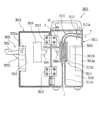
- the infusion pump 100 of this example is a peristaltic finger type infusion pump as in [Embodiment 1-1] described above, and includes a pump body (casing) 11 and a front side (tube mounting) of the pump body 11. And a door 12 for closing the position).
- the door 12 is swingably supported by the pump body 11 via hinges 14, 14, and extends from a position at which the front side of the pump body 11 is completely closed to a fully open position (for example, a position that opens 180 °). It can swing between.
- the infusion pump 100 of this example has the same configuration as the above [Embodiment 1-1] except for the configuration described below, its specific description is omitted.
- a tube mounting guide portion 111 and a pump portion 112 are provided at a substantially central portion (a central portion in the width direction) of the pump main body 11, and a clamp holding portion 117 is provided downstream of the pump portion 112. Is provided.
- the clamp holding portion 117 includes a holding recess 117a into which the clamp main body 71 of the roller clamp 7 shown in FIGS. 28 to 30 can be fitted from the bottom plate 71c side, and the roller clamp 7 ( With the clamp body 71) fitted, the infusion tube T is disposed along the vertical direction of the infusion pump 100, and the infusion tube T can be closed and opened by moving the roller 72 in the vertical direction.
- a lever housing recess 11c into which a lock lever 431 of a door lock mechanism 403, which will be described later, can enter is provided on the side of the pump body 11.
- a locking piece (a member having a hook shape (L-shaped cross section)) 434 on which the lock claw 433 of the lock piece 432 of the door lock mechanism 403 is hooked is provided on the upper portion of the lever receiving recess 11c.
- the pump body 11 is provided with a step portion 11d for avoiding interference with a rack gear 532 of a roller moving mechanism 503 described later.
- a lock lever 431 is disposed at the side end of the door 12 (the end opposite to the hinge 14 side).
- the lock lever 431 is provided so as to be rotatable about the rotation shaft 431a.
- the lock lever 431 is locked from the unlock position (unlock position) shown in FIG. 17 to the lock position (position shown in FIGS. 18 and 22). ) Can be swung (for example, can be swung approximately 90 °).
- a lock piece 432 is integrally formed with the lock lever 431.
- the lock piece 432 is a member formed in a substantially 1 ⁇ 4 circular shape, and is provided with a lock claw 433 at one end of the outer periphery.
- the lock lever 431 When the lock lever 431 is operated and placed in the lock position, the lock piece 432 is locked.
- the piece 432 and the lock claw 433 engage with the locking piece 434 provided on the pump main body 11 described above, and the door 12 is held in a completely closed state.
- an arcuate gear 435 centering on the axis of the rotation shaft 431a is formed on the outer periphery of the lock piece 432.
- This arc-shaped gear 435 meshes with a rack gear 532 of a roller moving mechanism 503 described later.
- the lock lever 431, the lock piece 432, the lock claw 433, and the locking piece 434 of the pump main body 11 constitute a door lock mechanism 403. By operating the lock lever 431, the door lock mechanism 403 can be placed in the locked or unlocked position.
- roller moving mechanism 503 will be described with reference to FIGS.
- the roller moving mechanism 503 in this example is a mechanism for moving the roller 72 of the roller clamp 7 held by the clamp holding portion 117 of the pump main body 11 between the closed position and the open position of the infusion tube T.
- the roller moving mechanism 503 includes a roller slider 531, a rack gear 532, the lock lever 431 and the lock piece 432 (arc-shaped gear 435) of the door lock mechanism 403 described above, and the like. Further, an operation force transmission mechanism (a mechanism for transmitting the rotation operation force of the lock lever 431 by converting it into a force for moving the roller 72 of the roller clamp 7) by the rack gear 532 and the lock piece 432 (arc-shaped gear 435) or the like. Is configured.
- the roller slider 531 includes a vertical piece 531d integrally attached to the rack gear 532, and a horizontal piece 531c extending in the horizontal direction (a direction parallel to the inner surface of the door 12) from the tip of the vertical piece 531d.
- release side press piece 531b which are extended in the direction orthogonal to the door 12 inner surface from the front-end
- the closing side pressing piece 531a and the opening side pressing piece 531b of the roller slider 531 are arranged along the vertical direction of the door 12, and the interval between the closing side pressing piece 531a and the opening side pressing piece 531b. Is set to a size larger than the diameter of the roller 72 of the roller clamp 7. Further, the closing side pressing piece 531a and the opening side pressing piece 531b of the roller slider 531 are arranged at positions corresponding to the holding recesses 117a of the clamp holding part 117 of the pump body 11 described above, and when the door 12 is closed. A part of the distal end portion of the closing side pressing piece 531a and a part of the distal end portion of the opening side pressing piece 531b enter the central portion of the holding concave portion 117a of the clamp holding portion 117.
- the rack gear 532 is disposed along the vertical direction of the door 12 and is supported by the support guides 127 and 128 provided on the inner surface of the door 12 so as to be slidable in the vertical direction. As described above, the rack gear 532 meshes with the arc-shaped gear 435 of the lock piece 432 of the door lock mechanism 403, and the lock lever 431 of the door lock mechanism 403 is in the open state (unlocked state) shown in FIG. Sometimes, the rack gear 532 (roller slider 531) is at the lowermost end. From this state, the lock lever 431 is operated to the lock side, and the lock claw 433 of the lock piece 432 is engaged with the engagement piece 434 of the pump body 11. When the state (door lock state) is reached, the rack gear 532 (roller slider 531) moves to the uppermost position (position shown in FIGS. 18 and 22).
- the infusion tube T is closed by operating the roller 72 of the roller clamp 7 of the infusion set S shown in FIG.
- the roller clamp 7 is brought to the front side of the pump body 11, and the clamp body 71 of the roller clamp 7 is attached to the flange 71f.
- the pump body 11 is fitted into the holding recess 117a in an upward position (see FIGS. 20 and 21).
- the infusion pump 100 is driven to perform the priming operation of the infusion set S.
- the infusion set S that has been subjected to the priming operation with the drop pressure before setting the infusion pump 100 may be set in the infusion pump 100.
- the preparation of the infusion is completed by the above processing, and then the infusion pump 100 is driven to start a predetermined infusion (infusion).
- the operation of the infusion pump 100 is stopped when the integrated time (or infusion integrated amount) from the start of the operation of the infusion pump 100 reaches a predetermined value.
- the lock lever 431 of the door lock mechanism 403 is rotated to the near side (outside of the lever housing recess 11c) (rotation operation opposite to that when the door is locked).
- the lock lever 431 is turned, the lock piece 432 is turned, and the lock piece 432 and the lock claw 433 are disengaged from the locking piece 434 of the pump body 11.
- the rack gear 532 that is, the roller slider 531 moves downward from the positions of FIGS. 24B and 25B.
- the closing side pressing piece 531 a of the roller slider 531 contacts the outer peripheral surface of the roller clamp 7, and the roller 72 is moved downward by the roller slider 531 from the contact point. It is pushed and rotates toward the closing side moving end of the clamp body 71 (the end opposite to the flange 71f).
- the lock lever 431 is returned to the position shown in FIG. 17, the roller 72 moves to the closing side moving end of the clamp body 71, and the infusion tube T is completely closed (FIG. 24A). Thereafter, the door 12 is opened, and the infusion tube T and the roller clamp 7 are removed from the infusion pump 100.
- the roller main body 11 is configured to hold the roller clamp 7, and the roller 72 of the roller clamp 7 is interlocked with the operation of the lock lever 431 of the door lock mechanism 403.
- the roller 72 of the roller clamp 7 is disposed at a position where the infusion tube T is opened, and the door locking mechanism 403 is in the unlocked state. Since the roller 72 of the roller clamp 7 is arranged at a position where the infusion tube T is closed, the roller clamp 7 is not limited as long as the door 12 is not locked even if the door 12 of the infusion pump is closed. As a result, the infusion tube T is kept closed. As a result, it is possible to reliably prevent a free flow due to incomplete closing of the door 12 or forgetting to lock the door.
- the infusion tube T When the door lock mechanism 403 is operated to open the door 12 in the closed state, the infusion tube T is automatically closed by the roller clamp 7 accordingly. Opening will no longer cause free flow. Further, after the infusion is finished, the infusion tube T is always closed by the roller clamp 7 when the door lock mechanism 13 is operated to the unlocked state before the door 12 is opened. The problem that “the infusion tube T is removed from the infusion pump 100” is also eliminated.
- the infusion pump of the present invention can prevent the free flow by holding the roller clamp 7 of the infusion tube T in the pump body 11, it is not necessary to use a dedicated clamp, and the general Even in a typical infusion tube, free flow can be prevented.
- the infusion pump 100 of this example it is possible to reliably prevent free flow caused by an operation error or the like of a medical staff such as a nurse.
- the roller clamp 7 is held on the pump body 11 in a vertical orientation (the orientation in which the rotation shafts 72a and 72b of the roller 72 are parallel to the front surface of the pump body 11).
- the roller clamp 7 may be held on the pump body 11 in a lateral orientation (posture shown in FIGS. 5 and 6).
- roller moving mechanism is provided on the door 12 side, but the roller moving mechanism may be provided on the pump body 11 side.
- the infusion set S shown in FIG. 46 has the same configuration as that described in the above [Embodiment 1-1], and includes an infusion bag B for storing a medicinal solution and a connecting needle S1 inserted into a port Bp of the infusion bag B.
- the roller clamp 7 provided in the middle of the infusion tube T on the downstream side, and the injection needle (venous needle) S3 connected to the tip of the infusion tube T are configured.
- the roller clamp 7 includes a clamp body 71 and a roller 72 as shown in FIGS.
- the clamp body 71 is a resin molded product in which a pair of side walls 71a and 71b and a bottom plate 71c that are opposed to each other with a predetermined interval are integrally formed.
- Guide grooves 711a and 711b are provided on the inner surfaces of the side walls 71a and 71b to guide and support the rotation shafts 72a and 72b of the roller 72.
- a V-groove 71e is formed on the bottom surface 71d of the clamp body 71 (the top surface of the bottom plate 71c).
- the bottom surface 71d of the clamp body 71 is inclined with respect to the guide grooves 711a and 711b, and the guide grooves 711a and 711b and the bottom surface are gradually moved from one end side (flange 71f side) of the clamp body 71 to the other end side.
- the distance from 71d is configured to be small.
- the roller 72 rotates along the guide grooves 711a and 711b between one end (end on the flange 71f side) of the clamp body 71 and the other end (end opposite to the flange 71f).
- the roller 72 is positioned at the moving end (opening side moving end) on the flange 71f side, the distance between the outer peripheral surface of the roller 72 and the bottom surface 71d of the clamp body 71 is maximized.
- the roller 72 is positioned at the opposite moving end (closing side moving end), the distance between the outer peripheral surface of the roller 72 and the bottom surface 71d of the clamp body 71 is minimized.
- the infusion tube T is inserted between the bottom surface 71d of the clamp body 71 and the outer peripheral surface of the roller 72, and the roller 72 is rotated to close the roller 72.
- the infusion tube T is completely closed.
- the roller 72 is rotationally moved from this state toward the flange 71f side of the clamp body 71, the pressing amount (flat amount) to the infusion tube T is reduced with the rotational movement of the roller 72, and the infusion tube T
- the volume of infusion that can flow inside increases.
- the infusion tube T will be in the state (completely open state) which is not pressed by the roller 72.
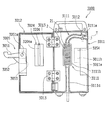
- the infusion pump 2001 in this example is a peristaltic finger type infusion pump, and includes a pump body (casing) 2011 and a door 2012 that closes the front surface side (tube attachment position) of the pump body 2011.
- the door 2012 is swingably (rotatably) supported by the pump main body 2011 via hinges 2014 and 2014. From the position at which the front side of the pump main body 2011 is completely closed, the door 2012 is fully opened (for example, 180 °). The position can be swung up to the open position).
- a tube mounting guide portion 2111 On the front surface of the pump main body 2011, a tube mounting guide portion 2111, a pump portion 2112 expanded from the tube mounting guide portion 2111 into a rectangular shape, and a clamp holding portion 2113 are provided in this order from the upstream side in the infusion feeding direction. .
- the groove width of the tube mounting guide portion 2111 has a size corresponding to the outer diameter of the infusion tube T of the infusion set described above.
- the tube mounting guide portion 2111 is formed in a shape (curved shape) curved in the lateral direction.
- a pressing plate 24 is provided on the inner surface of the door 2012.
- the pressing plate 24 is disposed at a position facing the distal ends of the plurality of fingers 21... 21 of the pump mechanism 2 with the door 2012 closed.
- the clamp holding portion 2113 includes a holding recess 2113a into which the clamp body 71 of the roller clamp 7 shown in FIGS. 46 to 49 can be fitted from the bottom plate 71c side, and the roller clamp 7 ( With the clamp body 71) fitted, the infusion tube T is disposed along the vertical direction of the infusion pump 2001, and the infusion tube T can be closed and opened by moving the roller 72 in the vertical direction.
- a locking recess 2011a into which an engagement member 2121 of a door lock mechanism 2005 described later can enter is provided at a side end of the pump main body 2011 (an end opposite to the hinge 2014).
- a vertical slit (bottom wall of the recess) 2110a of the lock recess 2011a is provided with a rectangular slit-shaped through hole 2110b (see FIGS. 36 to 39), and the lock lever 2005A (described later) is inserted through the through hole 2110b.
- the lock piece 2051 can project outside the pump body 2011 (inside the lock recess 2011a).
- the door 2012 is provided with an operation recess 2123 at a position corresponding to the clamp holding portion 2113 (a position facing the clamp holding portion 2113 when the door 2012 is closed) (see FIGS. 31 and 38, etc.).
- a vertical wall (wall body parallel to the front surface of the door) 2123a on the back side of the operation recess 2123 is formed on the side walls 71a and 71b of the roller clamp 7 held by the clamp holding portion 2113 of the pump main body 2011 with the door 2012 closed.
- the front surface (upper surface) comes into contact (or close proximity) (see FIG. 38).
- the upper and lower walls and the left and right sides of the operation recess 2123 are inclined walls that expand in the vertical and left and right directions toward the front side of the door 2012 in order to facilitate the rotation operation of a roller 72 described later.
- a rectangular slit-shaped roller through hole 2012a is provided in the vertical wall 2123a of the operation recess 2123.
- the roller through-hole 2012a has a slit width larger than the thickness (axial width) of the roller 72 of the roller clamp 7 by a predetermined amount, and the moving direction (vertical direction) of the roller clamp 7 held by the clamp holding portion 2113. Direction).
- the length in the vertical direction of the roller through hole 2012a is set to be larger than the moving range of the roller 72 of the roller clamp 7 (range from the open side moving end to the closing side moving end).
- an engaging member 2121 which is one of constituent members of a door lock mechanism 2005 described later is provided at a side end portion (an end portion opposite to the hinge 2014) of the door 2012.
- the engagement member 2121 is provided with an engagement hole 2121a into which a lock piece 2051 of a lock lever 2005A, which will be described later, can enter when the door 2012 is closed.
- the lock piece 2051 of the lock lever 2005A enters the engagement hole 2121a of the engagement member 2121 by an operation described later with the door 2012 closed, the lock piece 2051 and the engagement member 2121 are engaged,
- the engagement member 2121 around the hinge 2014 is prevented from turning, that is, the swinging (turning) of the door 2012 is prevented and the door 2012 is held in a completely closed state (door locked state).
- the inner wall 2120 of the door 2012 is provided with an opening 2120a for avoiding interference with the lock lever 2005A, the operating piece 2052, and the like.
- the pump mechanism 2 has the same configuration as the pump mechanism of [Embodiment 1-1] described above, and a plurality (see FIG. 1) arranged along one direction (the direction along the infusion tube T attached to the pump body 2011).
- the plate 24 and the holding frame 20 are configured.
- Openings 20a... 20a are provided at positions corresponding to the fingers 21 on the front side of the holding frame 20, and the front ends of the fingers 21 pass through the openings 20a on the front side of the holding frame 20 (infusion tube T). To the side). Further, the movement of the plurality of fingers 21... 21 in the axial direction (axial direction of the cam shaft 23) is restricted by the holding frame 20.
- Each finger 21 is a plate-like member, and can be moved (moved forward and backward) individually while sliding on each other.
- Each cam 21 has a cam hole 21a.
- a disc-shaped eccentric cam 22 is fitted in each cam hole 21a.
- Each eccentric cam 22 is rotatable in the cam hole 21 a, and these eccentric cams 22... 22 are integrally attached to the cam shaft 23.
- Each eccentric cam 22 has its disk center eccentric with respect to the cam shaft 23. As shown in FIG. 43, when the cam shaft 23 makes one rotation (360 ° rotation), the tip of the finger 21 advances most. It reciprocates once between the position (tube closed position) and the last retracted position (tube fully open position).
- the plurality of eccentric cams 22 are attached to the camshaft 23 with a predetermined phase difference (phase difference in the rotational direction of the camshaft 23). Specifically, the eccentric cams 22... 22 have a phase difference (360 ° / the number of the eccentric cams 22) such that the tips of the fingers 21. ) Is attached to the camshaft 23.
- FIG. 43 shows the position of the finger 21 every time the camshaft 23 rotates 90 °.
- the cam shaft 23 of the pump mechanism 2 is provided along the vertical direction (the arrangement direction of the plurality of fingers 21, 21).
- a lower end portion of the cam shaft 23 is rotatably supported by a bearing 26 provided on the holding frame 20.
- the upper portion of the cam shaft 23 protrudes upward through the wall body of the holding frame 20.
- a bearing 25 is provided at the penetrating portion of the cam shaft 23, and the upper portion of the cam shaft 23 is rotatably supported by the bearing 25.
- a timing pulley (driven pulley) 201 is attached to the upper end of the camshaft 23 so as to rotate together.
- a timing belt 203 is wound between the timing pulley 201 of the cam shaft 23 and a timing pulley (driving pulley) 202 attached integrally to the rotating shaft 41 of an electric motor (for example, a stepping motor) 4.
- the cam shaft 23 is rotated by driving the electric motor 4.
- the electric motor 4 is driven and controlled (rotational speed control) by the control unit 2003.
- the electric motor 4 is supplied with electric power from a battery built in the infusion pump 2001 or a commercial power source.
- each eccentric cam 22 is rotated in the cam hole 21 a of the finger 21.
- each finger 21 advances / retreats sequentially from the upstream side (upstream side in the infusion feeding direction) to the downstream side.
- the distal end portion of the finger 21 moves in a peristaltic wave shape from the upstream side to the downstream side.
- a peristaltic motion is imparted to the infusion tube T disposed between the distal ends of the fingers 21.
- the infusion in T is sent out from the upstream side to the downstream side.
- a buffer sheet 24 a is provided between the pressing plate 24 and the base plate 15 in order to reduce the overload that the infusion tube T receives from the fingers 21.
- the control unit 2003 is configured mainly with a microcomputer or the like.
- the control unit 2003 controls the electric motor 4 according to the set value of the infusion flow rate (infusion rate per unit time) set by operating the operation panel 2122 (see FIG. 31) installed on the front surface of the door 2012. It is possible to variably adjust the infusion flow rate by controlling the number of rotations, for example, the infusion flow rate can be set in units of [1 mL / h] within the range of 1 mL / h to 1200 mL / h.
- control unit 2003 displays operation information such as “infusion flow rate (injection amount)” and “injection integration time” on the operation panel 2122, and displays “abnormal air bubble mixing”, “door closing failure”, and the like. It is configured to display various warnings including.
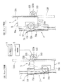
- the door lock mechanism 2005 in this example includes a lock lever 2005A, a fulcrum shaft 2053 provided on the back surface of the front wall 2110 of the pump body 2011, a lock spring 2054, an engagement member 2121 provided on the door 2012, and the like. Yes.
- the lock lever 2005A includes a lever piece 2050, a lock piece 2051, and an operating piece (input piece) 2052.
- the lever piece 2050 is integrally formed with a vertical arm 2050a extending along the vertical direction of the pump main body 2011 and a horizontal arm 2050b extending along the horizontal direction of the pump main body 2011 (a direction orthogonal to the vertical arm 2050a).
- a lock piece 2051 is integrally formed at the tip of the vertical arm 2050a (one end side of the lock lever 2005A).
- the lock piece 2051 is a plate-like member extending in a direction orthogonal to the vertical arm 2050a. As described above, the lock piece 2051 can protrude to the outside through the through hole 2110b provided in the vertical wall 2110a of the locking recess 2011a.
- the lateral arm 2050b includes a first lateral piece 2501b extending in the lateral direction of the pump body 2011, and a connecting piece 2502b extending from the tip of the first lateral piece 2501b to the front side of the pump body 2011 along the front-rear direction of the pump body 2011.
- a second horizontal piece 2503b extending in the lateral direction of the pump body 2011 from the front end of the connecting piece 2502b is integrally formed, and an operating piece 2052 is provided at the front end of the second horizontal piece 2503b (the other end side of the lock lever 2005A).
- the operating piece 2052 is a plate-like member extending along the vertical direction of the pump main body 2011. As shown in FIGS. 32 to 40, the operating piece 2052 is disposed at the lower center of the clamp holding portion 2113. With the roller clamp 7 held by the clamp holding portion 2113, the distal end portion 2052a of the operating piece 2052 is provided. Is opposed to the outer peripheral surface of the roller 72 of the roller clamp 7. That is, the operating piece 2052 is disposed at a position where the tip end portion 2052 a can contact the outer peripheral surface of the roller 72 of the roller clamp 7.
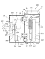
- the vertical arm 2050a (lock piece 2051), the first horizontal piece 2501b of the horizontal arm 2050b, and a part of the connecting piece 2502b are on the back side of the front wall 2110 of the pump body 2011.
- the remaining part of the connecting piece 2502b and the second horizontal piece 2503b (operating piece 2052) are arranged on the front side of the front wall 2110 of the pump body 2011.
- the connecting piece 2502b faces the front side and the back side of the front wall 2110 through a through hole 2110c opened in the front wall 2110.
- the vertical arm 2050a and the horizontal arm 2050b are connected so as to be orthogonal to each other.
- a connecting portion 2050c between the vertical arm 2050a and the horizontal arm 2050b is rotatably supported by a fulcrum shaft 2053, and the entire lock lever 2005A can rotate (swing) around the fulcrum shaft 2053.
- the lock piece 2051 can move to the locked position shown in FIGS. 32, 34, and 37 and the unlocked position shown in FIGS.
- a positioning member (protrusion) 2056 is provided on the side of the vertical arm 2050a of the lock lever 2005A to define the amount of protrusion of the lock piece 2051 into the locking recess 2011a (movement of the lock piece 2051).
- the lock piece 2051 is positioned at the lock position in a state where the vertical arm 2050a of the lock lever 2005A hits the positioning member 2056.
- the fulcrum shaft 2053 is a stepped shaft (axis perpendicular to the front wall 2110) protruding from the back surface of the front wall 2110 of the pump main body 2011, and the coupling portion 2050c of the lever piece 2050 is connected to the small diameter portion 2053a.
- the fitting hole (fulcrum hole) 2050d provided in is fitted.
- a pin 2055 is attached to the tip of the small diameter portion 2053a of the fulcrum shaft 2053.
- a lock spring (torsion coil spring) 2054 is disposed between the pin 2055 and the lever piece 2050 (coupling portion 2050c). One end of the lock spring 2054 is locked to the pin 2055. Further, the other end of the lock spring 2054 is engaged with the first horizontal piece 2501b of the lever piece 2050, and the lever piece 2050 is moved in the direction of the arrow in FIG. It is urged clockwise (lock side) when viewed from the front.
- the lock piece 2051 is brought into the locked position shown in FIGS. 32, 34 and 37 by the elastic force of the lock spring 2054. Be placed.
- a downward force force away from the pump portion 2112
- the lock lever 2005A is counterclockwise about the fulcrum shaft 2053 (counterclockwise as viewed from the front of the pump main body 2011).
- the lock piece 2051 is arranged at the unlocked position. .
- the elastic force of the lock spring 2054 is set smaller than the force by which the nurse 72 rotates the roller 72 of the roller clamp 7 and presses the operating piece 2052 with the roller 72.
- the lock lever 2005A can be rotated against the elastic force of the lock spring 2054 by roller operation.
- the roller clamp 7 is brought to the front side of the pump body 2011, and the clamp body 71 of the roller clamp 7 is moved upward with the flange 71f facing upward. In this posture, it is fitted into the clamp holding portion 2113 (holding recess 2113a) of the pump body 2011 (see FIGS. 35 and 40A). Specifically, first, in a state where the roller clamp 7 is disposed on the upper side of the clamp holding portion 2113, the infusion tube T on the downstream side of the roller clamp 7 is connected to the operating piece 2052 of the lock lever 2005A and the clamp holding portion 2113. The infusion tube T is inserted between the side wall 2113b (see FIGS.
- the clamp body 71 is fitted into the holding recess 2113a while sliding the roller clamp 7 and the infusion tube T downward.
- the roller clamp 7 is fitted into the holding recess 2113a in a state in which the lock lever 2005A is turned to the non-locking side (turned counterclockwise when viewed from the front of the pump main body 2011) with an index finger or the like.
- the roller clamp 7 is held in the clamp holding portion 2113 by a method in which the roller clamp 7 is fitted into the holding recess 2113 a while the operating piece 2052 is pushed down by the roller 72 of the roller clamp 7.
- the tip end portion 2052a of the operating piece 2052 of the lock lever 2005A is a roller
- the lock piece 2051 is disposed at the non-lock position by contacting the outer peripheral surface of the roller 72 positioned at the closing side moving end of the moving range.
- the infusion pump 2001 After completing such tube setting, the infusion pump 2001 is driven to perform the priming operation of the infusion set S. Instead of the priming operation by driving the infusion pump 2001, the infusion set S that has been subjected to the priming operation with the drop pressure before setting the infusion pump 2001 may be set in the infusion pump 2001.
- the preparation of the infusion is completed by the above processing, and then the infusion pump 2001 is driven to start a predetermined infusion (infusion).
- the door lock mechanism As described above, according to the infusion pump 2001 of this example, when the door 2012 is in the closed state (the door is locked), unless the roller 72 of the roller clamp 7 is operated to the tube closed position, the door lock mechanism The state where the lock piece 2051 and the engagement member 2121 of 2005 are engaged (the door is locked) is maintained. Thereby, even if it tries to open the door 2012 accidentally during infusion, since the door 2012 cannot be opened, the free flow by an incorrect operation can be prevented.
- the infusion pump 2001 of this example it is possible to reliably prevent free flow caused by an operation error or the like of a medical staff such as a nurse.
- the infusion pump 2001 needs to be closed when the infusion pump 2001 is carried or stored unused, the following operation may be performed.
- a plate member, bar member, or the like (or the roller 72 of the roller clamp 7) is inserted into the roller through-hole 2012a of the door 2012 from the front side of the door, and the operating piece 2052 of the lock lever 2005A is pushed down so that the lock piece 2051 is unlocked.
- the door 2012 is closed and the door 2012 is locked in a completely closed state by removing a plate material, a bar, or the like.
- a plate material, a bar, or the like is inserted into the roller through-hole 2012a of the door 2012 from the front side of the door, and the operating piece 2052 of the lock lever 2005A is pushed down to release the lock piece 2051. What is necessary is just to perform operation of opening the door 2012 in the state arrange
- a torsion coil spring is used as the lock spring 2054 that biases the lock piece 2051 toward the lock position.
- the present invention is not limited to this, and for example, a compression coil spring, a tension coil spring, and the like. Any other spring (elastic member) may be applied as long as the lock piece 2051 (lock lever 2005A) can be biased toward the lock position.
- the lock piece 2051 (lock lever 2005A) is provided on the pump body 2011 side, and the engaging member 2121 is provided on the door 2012 side.
- the present invention is not limited to this, and the lock piece 2051 is provided on the door 2012.
- the engaging member may be provided on the pump body 2011 side.
- the infusion pump of this example is a peristaltic finger-type infusion pump as in [Embodiment 2-1] described above, and the pump main body 2011 and the front side (tube attachment position) of the pump main body 2011 are closed.
- Door 2012 (see FIGS. 31 and 32).
- the door 2012 is swingably (rotatably) supported by the pump main body 2011 via hinges 2014 and 2014, and opens from the position where the front side of the pump main body 2011 is completely closed (for example, 180 degrees). Oscillate until the position).
- the infusion pump of this example has the same configuration as the above [Embodiment 2-1] except for the configuration described below, the specific description thereof will be omitted.
- the infusion pump of this example includes a roller position sensor 2600 and an electric door lock mechanism 2700 (none of which are shown).
- the roller position sensor 2600 is, for example, a known photoelectric sensor (reflection type) composed of a light emitting element and a light receiving element, and the roller 72 of the roller clamp 7 held in the clamp holding part 2113 of the pump main body 2011 is in a tube release position ( A roller detection signal (ON signal) is output when it is at the opening side moving end (see FIG. 37).
- a transmissive photoelectric sensor having a structure in which a light emitting element and a light receiving element are arranged to face each other may be used.
- other known position / article detection means such as a limit switch that is turned on (or turned off) when the roller 72 is located at the tube release position (open side moving end), for example. You may apply.
- the electric door lock mechanism 2700 uses, for example, a solenoid as an actuator, locks the door 2012 in a closed state when the output signal of the roller position sensor 2600 is an ON signal, and locks the door 2012 when it is an OFF signal. Is released (non-locked state).
- the roller 72 of the roller clamp 7 held by the clamp holding portion 2113 of the pump main body 2011 is rotationally moved from the tube closing side to the tube opening position (opening side moving end).
- the detection signal of the lock position sensor 600 is switched from the OFF signal to the ON signal, and the door lock mechanism 2700 is activated accordingly, and the door 2012 is locked.
- the detection signal of the lock position sensor 600 is switched from the ON signal to the OFF signal, and the lock by the door lock mechanism 2700 is released accordingly, and the door 2012 is unlocked. It becomes a state.
- the finger-type infusion pump is, for example, a plurality of fingers arranged in the pump body, a cam that individually drives the fingers forward and backward, and a state in which the door is closed, provided on the door side of the pump
- a pump mechanism having a pressing plate or the like disposed opposite to the tips of the plurality of fingers, and an infusion tube (for example, made of polyvinyl chloride or polybutadiene) connected to an infusion bag is connected to a pump body (a plurality of The infusion tube is arranged between the plurality of fingers and the pressing plate by mounting on the front side of the finger and closing the door.
- each finger is individually moved forward and backward by a cam, so that the infusion tube can be sequentially pressed by each finger and the infusion can be sent out by a peristaltic motion (for example, Japanese Patent Application Laid-Open No. 2008-113726). JP-A-5-076596 and JP-A-11-342199).
- the door is swingably supported on the pump body via a hinge.
- the hinge part is caused by the impact of the drop. “Gat” may occur.
- “rattle” occurs in the hinge portion.
- the distance (distance) between the finger tip of the pump mechanism and the pressing plate in a state where the door is closed may be increased.
- the purpose of this example is to provide a finger-type infusion pump capable of notifying medical personnel such as nurses of abnormalities in the infusion flow rate caused by pump dropping or the like. .
- a plurality of fingers arranged in one direction, a cam for individually driving the fingers forward and backward, and a door for closing the front side of the plurality of fingers so as to be opened and closed are provided.
- a pump mechanism having a pressing plate disposed to face the front end portions of the plurality of fingers in a state where the door is closed, and by closing the door, the plurality of fingers of the pump mechanism and the pressing plate
- the infusion pump that sends out the infusion by a peristaltic motion by driving the fingers forward and backward with the infusion tube in between, the door is closed and the finger of the pump mechanism is closed.
- Abnormality notification means for example, control unit 3003, display panel 3) for notifying abnormality when a value related to the distance between the tip and the pressing plate is larger than a predetermined allowable value. There may be mentioned those having a 21 and a buzzer device 3009, etc.).
- the infusion pump having such a configuration, when the value related to the distance between the finger tip of the pump mechanism and the door-side pressing plate when the door is in the closed state is larger than a predetermined allowable value, an abnormality is caused. If there is an abnormality that causes an increase in the infusion flow rate due to a drop in the infusion pump, etc. due to the drop of the infusion pump, etc. Can inform health care professionals. As a result, infusion can be prevented when the infusion flow rate is abnormal.
- the allowable value set for the interval between the finger tip and the pressing plate in the door closed state is, for example, an interval (finger flow) at which a rapid increase (free flow) of the infusion flow rate caused by a pump drop or the like does not occur.
- the upper limit value of the distance between the tip and the pressing plate may be obtained by experiment / calculation and set in consideration of the upper limit value.
- an interval detecting means for example, a distance sensor
- an interval detecting means that detects an interval between the distal end of the finger at the most retracted position or the most advanced position and the pressing plate in the closed state of the door.
- distance detection means distance sensors
- the hinge portion of the door may become loose. Even if the door is tilted obliquely with respect to the pump body (front wall), the finger tip and the door in the closed state of the door based on the detection values of the two distance detection means (distance sensors) It is possible to accurately determine whether or not the distance between the side pressing plate is within a normal range (within an allowable value).
- the door is closed by providing a limit switch that is turned on when the distance between the finger tip of the pump mechanism and the pressing plate on the door side is larger than the allowable value when the door is closed.
- a limit switch that is turned off when the distance between the finger tip of the pump mechanism and the pressing plate on the door side is larger than an allowable value when the door is closed may be used.
- a plurality of fingers arranged in one direction, a cam for individually driving the fingers forward and backward, and a front side of the plurality of fingers are closed in an openable and closable manner.
- a pump mechanism having a pressing plate provided on the door and disposed opposite to the front end portions of the plurality of fingers in a state where the door is closed, and the plurality of fingers of the pump mechanism and the In the infusion pump which sends out the infusion by peristaltic motion by driving the fingers forward and backward with respect to the infusion tube in a state where the infusion tube is disposed between the pressure plate and the infusion tube, the press plate is in an infusion tube with the door closed.
- Pressure detection means for example, a pressure sensor
- pressure detection means for detecting pressure received from the pressure, and pressure detected by the pressure detection means when the door is closed It can be given a configuration that notifies the abnormality is smaller than a predetermined allowable value.
- the pressure plate when the door is closed, the pressure plate receives from the infusion tube when the distance between the distal end of the finger at the most advanced position and the pressure plate on the door side is normal.
- the pressing plate Paying attention to the fact that the pressure acting on the pressure decreases, the pressure detected by the pressure detecting means (pressure acting on the pressing plate) when the door is closed is lower than a predetermined allowable value. It is characterized by notifying abnormality when it is small.
- the infusion pump 3001 of this example is a peristaltic finger type infusion pump, and includes a pump body (casing) 3011 and a door 3012 that closes the front side (tube attachment position) of the pump body 3011.
- the door 3012 is swingably (rotatably) supported by the pump main body 3011 via hinges 3013 and 3013, and opens from the position where the front side of the pump main body 3011 is completely closed (for example, 180 ° is opened). Oscillate until the position).
- the pump main body 3011 and the door 3012 are provided with a door lock mechanism 3005 for holding the closed state when the door 3012 is closed.
- the door lock mechanism 3005 will be described later.
- the pump main body 3011 is provided with a tube mounting guide (guide groove) 3111.
- the tube mounting guide 3111 includes an upstream guide portion 3111a, a pump portion 3111b enlarged from the upstream guide portion 3111a in a rectangular shape, and a downstream guide portion 3111c in this order from the upstream side in the infusion feeding direction.
- the front end portion of fingers 21... 21 of the pump mechanism 2 to be described later faces the pump portion 3111b.
- the upstream guide portion 3111a of the tube mounting guide 3111 is formed in a shape (curved shape) curved in the lateral direction. Further, the downstream guide portion 3111c on the downstream side of the pump portion 3111b is formed in a shape extending linearly in the vertical direction.
- the groove width of the upstream guide portion 3111a and the groove width of the downstream downstream guide portion 3111c are respectively large corresponding to the outer diameter of an infusion tube (for example, made of polyvinyl chloride or polybutadiene) T connected to the chemical solution bag.
- the infusion tube T can be attached to the infusion pump 3001 by fitting the infusion tube T into the upstream guide portion 3111a and the downstream guide portion 3111c.
- a tube clamp 3112 is provided on the upstream guide portion 3111a.
- the tube clamp 3112 is a member that temporarily holds the infusion tube T when the tube is attached to the infusion pump 3001, and the clamp is automatically released when the door 3012 is closed after the tube is attached.
- a clamp lever (not shown) is provided in the vicinity of the tube clamp 3112. When the infusion tube T is mounted, the tube clamp 3112 can be opened by operating the crank lever. it can.
- a lever housing recess 3011a into which a lock lever 3051 of a door lock mechanism 3005 described later can enter is provided at the side end of the pump body 3011 (the end opposite to the hinge 3013). Further, a lock chamber 3011b into which a lock piece 3052 described later can enter is provided inside the lever housing recess 3011a. A locking piece 3054 on which the lock claw 3053 of the lock piece 3052 is hooked is provided on the upper portion of the lock chamber 3011b.
- a lock lever 3051 is disposed at the side end of the door 3012 (the end opposite to the hinge 3013).
- the lock lever 3051 is provided so as to be rotatable about the rotation shaft 3051a.
- the lock lever 3051 is locked from the unlock position (unlock position) shown in FIG. 51 to the lock position (position shown in FIGS. 52 and 54). ) Can be swung (for example, can be swung approximately 90 °).
- a lock piece 3052 is integrally formed with the lock lever 3051.
- a lock claw 3053 is provided at the tip of the lock piece 3052. When the lock lever 3051 is operated and placed at the lock position, the lock claw 3053 is engaged with the locking piece 3054 provided in the pump main body 3011 described above.
- the door 3012 is held in a completely closed state.
- the lock lever 3051, the lock piece 3052, the lock claw 3053, and the locking piece 3054 of the pump main body 3011 constitute a door lock mechanism 3005, and the door lock mechanism 3005 is operated by operating the lock lever 3051. Can be placed in the locked or unlocked position.
- a pressing plate 3024 is provided on the inner surface side of the door 3012.
- the pressing plate 3024 faces the tip 21b of the finger 21 (finger 21 at the most retracted position) of the pump mechanism 2 with a predetermined gap Ga (see FIG. 60) with the door 3012 closed.
- a rectangular detected portion 3241 is integrally formed on the pressing plate 3024.
- the detected surface 3241 a of the detected portion 3241 is on the same plane as the pressing surface (front surface) of the pressing plate 3024.
- the detected portion 3241 is provided at a position corresponding to a distance sensor 3006 (details will be described later) disposed on the pump main body 3011, and the detected surface 3241 a of the detected portion 3241 with the door 3012 closed. And the detection surface 3006a of the distance sensor 3006 are opposed to each other (see FIGS. 54 and 60).
- the door 3012 When setting the infusion tube T to the infusion pump 3001 having the above configuration, the door 3012 is opened, and the infusion tube T connected to the chemical solution bag is connected to the [upstream guide portion 3111a] ⁇ [tube clamp 3112] ⁇ [pump The infusion tube T is attached by fitting in the order of the portion 3111b] ⁇ [downstream guide portion 3111c]. After such tube installation is completed, the door 3012 is closed, and the door 3012 is locked in the closed state by the door lock mechanism 3005, whereby the setting of the infusion tube T is completed. In this example, as described above, in the state where the door 3012 is closed, the tube clamp 3112 of the upstream guide portion 3111a is opened. Further, when the door 3012 is opened after completion of the infusion, the infusion tube T is closed by the tube clamp 3112, and so-called free flow is prevented.
- the pump mechanism 2 has a plurality (13 in the example shown in FIG. 54) of fingers 21... 21 arranged along one direction (a direction along the infusion tube T attached to the pump body 3011), and each of the fingers 21.
- fingers 21... 21 are respectively constituted by eccentric cams 22... 22 for individually moving forward and backward, a cam shaft 23 for rotating each eccentric cam 22, the pressing plate 3024, the holding frame 20, and the like.
- Openings 20a... 20a are provided at positions corresponding to the fingers 21 on the front side of the holding frame 20, and the front ends of the fingers 21 pass through the openings 20a on the front side of the holding frame 20 (infusion tube T). To the side). Further, the movement of the plurality of fingers 21... 21 in the axial direction (axial direction of the cam shaft 23) is restricted by the holding frame 20.
- Each finger 21 is a plate-like member, and can be moved (moved forward and backward) individually while sliding on each other.
- Each cam 21 has a cam hole 21a.
- a disc-shaped eccentric cam 22 is fitted in each cam hole 21a.
- Each eccentric cam 22 is rotatable in the cam hole 21 a, and these eccentric cams 22... 22 are integrally attached to the cam shaft 23.
- Each eccentric cam 22 has its disc center decentered with respect to the cam shaft 23. As shown in FIG. 56, when the cam shaft 23 makes one rotation (360 ° rotation), the tip of the finger 21 advances most. It reciprocates once between the position (tube closed position) and the last retracted position (tube fully open position).
- the plurality of eccentric cams 22 are attached to the camshaft 23 with a predetermined phase difference (phase difference in the rotational direction of the camshaft 23). Specifically, the eccentric cams 22... 22 have a phase difference (360 ° / the number of the eccentric cams 22) such that the tips of the fingers 21. ) Is attached to the camshaft 23.
- FIG. 56 shows the position of the finger 21 every time the camshaft 23 rotates 90 °.
- the cam shaft 23 of the pump mechanism 2 is provided along the vertical direction (the arrangement direction of the plurality of fingers 21... 21).
- a lower end portion of the cam shaft 23 is rotatably supported by a bearing 26 provided on the holding frame 20.
- the upper portion of the cam shaft 23 protrudes upward through the wall body of the holding frame 20.
- a bearing 25 is provided at the penetrating portion of the cam shaft 23, and the upper portion of the cam shaft 23 is rotatably supported by the bearing 25.
- a timing pulley (driven pulley) 201 is attached to the upper end of the camshaft 23 so as to rotate together.
- a timing belt 203 is wound between the timing pulley 201 of the cam shaft 23 and a timing pulley (driving pulley) 202 attached integrally to the rotating shaft 41 of an electric motor (for example, a stepping motor) 4.
- the cam shaft 23 is rotated by driving the electric motor 4.
- the electric motor 4 is driven and controlled (rotational speed control) by the control unit 3003.
- the electric motor 4 is supplied with power from a battery built in the infusion pump 3001 or a commercial power source.
- each eccentric cam 22 is rotated in the cam hole 21 a of the finger 21.
- each finger 21 advances / retreats sequentially from the upstream side (upstream side in the infusion feeding direction) to the downstream side.
- the distal end portion of the finger 21 moves in a peristaltic wave shape from the upstream side to the downstream side.
- a peristaltic motion is imparted to the infusion tube T disposed between the distal ends of the fingers 21.
- the infusion in T is sent out from the upstream side to the downstream side.
- a buffer sheet 3024 a is provided between the pressing plate 3024 and the base plate 3015 in order to reduce the overload that the infusion tube T receives from the fingers 21.
- the infusion pump 3001 of this example when the electric motor 4 is in a stopped state, one finger 21 or two fingers 21 among the plurality of fingers 21.
- the infusion tube T is completely closed by one finger 21 or two fingers 21 of the pump mechanism 2 in a state where the door 3012 is closed.
- the control unit 3003 is configured mainly with a microcomputer or the like. As shown in FIG. 59, the control unit 3003 detects a bubble sensor (for example, an ultrasonic sensor) 3007 for detecting bubbles mixed in the infusion tube T to which the pump body 3011 is attached, a closed state of the door 3012, and the like. An occlusion sensor 3008, a distance sensor 3006, which will be described later, and the like are connected, and an output signal of each sensor is input to the control unit 3003.
- a bubble sensor for example, an ultrasonic sensor
- An occlusion sensor 3008, a distance sensor 3006, which will be described later, and the like are connected, and an output signal of each sensor is input to the control unit 3003.
- the control unit 3003 is connected to the electric motor 4 for driving the pump mechanism 2, the buzzer device 3009, the display operation unit 3120 (see FIG. 50) installed on the front surface of the door 3012, and the like.
- the display operation unit 3120 includes a display panel (liquid crystal display) 3121 and an operation panel 3122.
- the control unit 3003 operates the electric motor of the pump drive mechanism 2 in accordance with the set value of the infusion flow rate (infusion feed amount per unit time) set (input) by operating the operation panel 3122 of the display operation unit 3120.
- the infusion flow rate is variably adjusted by controlling the rotation speed of the motor 4.
- the infusion flow rate can be set in units of [1 mL / h] within a range of 1 mL / h to 1200 mL / h.
- control unit 3003 displays the operation information such as “infusion flow rate (injection amount)” and “infusion integration time” on the display panel 3121 of the display operation unit 3120, and the infusion solution based on the output signal of the bubble sensor 7.
- control unit 3003 displays “abnormal flow rate” on the display panel 3121 and performs a process of operating the buzzer device 3009 by a process described later.
- the most retracted position (the tube complete position) among the plurality of fingers 21.
- the distance Ga (see FIG. 60A) between the distal end 21b of the finger 21 in the open position) and the pressing plate 3024 on the door 3012 side (the surface on the finger 21 side) is designated as an infusion tube T (circular state).
- the same dimension as the diameter (outer diameter).
- the tip 21b of the finger 21 and the pressing plate when one finger 21 is moved from the most retracted position (tube fully open position) to the most advanced / retracted position (tube fully closed position).
- the interval Gb between the fluid and the tube 3024 is set to a size (Gb ⁇ 2t) smaller by a predetermined amount than twice the wall thickness t of the infusion tube T. 60 and 56, “St” is a stroke from the most retracted position of the finger 21 to the most advanced / retreated position.
- the door 3012 is swingably supported by the pump body 3011 via hinges 3013 and 3013, and when the infusion pump 3001 is dropped on the floor or the like, the door 3012 is dropped.
- a rattling occurs in the hinge portion due to the impact.
- the cumulative number of times of door opening and closing increases due to long-term use or the like, there is a case where “rattle” occurs in the hinge portion.
- the rattling occurs in the hinge portion in this way, the distance between the tip 21b of the finger 21 of the pump mechanism 2 and the pressing plate 3024 on the door 3012 side with the door 3012 closed may be increased. Yes (see FIG. 60C).
- the infusion flow rate may increase rapidly.
- a distance sensor 3006 is provided in the pump main body 3011 as shown in FIGS.
- the distance sensor 3006 is disposed in the vicinity of the side of the pump unit 3111b and at the center of the pump unit 3111b in the vertical direction (infusion feeding direction).
- the distance sensor 3006 is a reflective photoelectric sensor that detects the distance from the detection surface 3006a to the detection surface.
- the detection surface 3006a of the distance sensor 3006 includes a tip 21b of the finger 21 at the last retracted position (tube fully open position) of the plurality of fingers 21. Match. That is, the detection surface 3006a of the distance sensor 3006 and the tip 21b of the finger 21 at the most retracted position are located on the same plane parallel to the front wall 110 (see FIG. 51 and the like) of the pump body 3011.
- the detection surface 3006a of the distance sensor 3006 and the detected surface 3241a provided on the pressing plate 3024 on the door 3012 side face each other with the door 3012 closed.
- the distance (distance) between the detection surface 3006a of the distance sensor 3006 and the detected surface 3241a of the pressing plate 3024 by the distance sensor 3006, that is, the tip 21b of the finger 21 at the last retracted position in the closed state of the door 3012. (Ga) between the door 3012 and the pressing plate 3024 on the door 3012 side is detected.
- An output signal of the distance sensor 3006 is input to the control unit 3003.
- the controller 3003 determines the distance between the detection surface 3006a of the distance sensor 3006 and the detected surface 3241a of the pressing plate 3024 (the tip of the finger 21). 21b and the pressing surface of the pressing plate 3024) is determined whether it is larger than a predetermined allowable value Gath, and the distance detected by the distance sensor 3006 is larger than the allowable value Gath. 50 and the display panel 3121 of the display operation unit 3120 shown in FIG. 49, “abnormal flow rate” is displayed, and the buzzer device 3009 is activated to notify the medical staff such as a nurse of the abnormality.
- the detection value of the distance sensor 3006 in the closed state of the door 3012 (the distance between the tip 21b of the finger 21 and the pressing surface of the pressing plate 3024) is larger than the allowable value Gath. In this case, the driving of the electric motor 4 of the pump mechanism 2 may be prohibited.
- the allowable value Gath for example, the distance (Gb: diagram) between the tip 21b of the finger 21 at the most advanced position (tube fully closed position) and the pressing surface of the pressing plate 3024 in the closed state of the door 3012. 60)) as a parameter, an upper limit value GbLIM of an interval (interval between the finger tip and the pressing surface) at which free flow (free flow due to pump dropping or the like) does not occur is obtained in advance by experiments and calculations, Set according to the result.
- the infusion pump of this example due to the drop of the infusion pump 3001 or the like, there is an abnormality in which the distance between the finger tip 21b and the pressing plate 3024 in the door closed state increases and the infusion flow rate rapidly increases.
- the abnormality can be notified to a health care worker such as a nurse.
- infusion with an abnormal infusion flow rate can be prevented, and excessive infusion of the infusion can be prevented in advance.
- the distance sensor 3006 (the surface to be detected 3241a) is arranged at one place, but the present invention is not limited to this, and the distance sensor 3006 is provided at two places, the upstream end and the downstream end of the pump 3111b. May be arranged. In this case, even if the door 3012 is inclined with respect to the front wall 110 of the pump body 3011 due to the rattling of the hinge 3013 portion, the door 3012 is based on the detection values of the two distance sensors 3006. It is possible to accurately determine whether or not the distance between the tip of the finger 21 of the pump mechanism 2 in the closed state and the pressing plate 3024 on the door 3012 side is within a normal range (within an allowable value).
- the distance between the distal end 21b of the finger 21 at the most retracted position in the closed state of the door 3012 and the pressing plate 3024 on the door 3012 side is detected.
- the distance between the tip 21b of the finger 21 at the most advanced position in the closed state and the pressing plate 3024 on the door 3012 side may be detected by a distance sensor.
- the interval detected by the distance sensor is larger than the allowable value (GbLIM ⁇ margin)
- “flow rate abnormality” is displayed on the display panel 3121 of the display operation unit 3120 and the buzzer device 3009 is displayed. It only has to operate to inform the health care worker such as a nurse of the abnormality.
- a reflective photoelectric sensor is used as the distance sensor 3006.
- the present invention is not limited to this, and other types of distance sensors such as a capacitance sensor and an ultrasonic sensor may be used. Good.
- the distance sensor 3006 is used, and the flow rate abnormality is notified when the detected value of the distance sensor 3006 is larger than the allowable value.
- a limit switch is used instead of such a distance sensor 3006. May be.
- a limit switch 3060 (not shown) is provided at the arrangement position of the distance sensor 3006 shown in FIGS. 51 and 54, and the actuator of the limit switch 3060 is pressed by the pressing plate 3024 with the door 3012 closed. It is made to contact
- the limit switch 3060 is turned off so that the tip 21b of the finger 21 and the pressing plate 3024
- the actuator of the limit switch 3060 is separated from the contacted portion 241 of the pressing plate 3024 and the limit switch 3060 is turned on.
- a limit switch that is turned off when the distance between the tip 21b of the finger 21 of the pump mechanism 2 and the pressing plate 3024 on the door 21 side is larger than an allowable value when the door 3012 is closed is used. May be.
- the infusion pump 3100 of this example is a peristaltic finger type infusion pump, and includes a pump body (casing) 3011 and a door 3012 that closes the front side (tube attachment position) of the pump body 3011.
- the door 3012 is provided with a pressing plate 3024, and the pressing plate 3024 faces the fingers 21.. 21 of the pump mechanism 2 with the door 3012 closed.
- the infusion pump 3100 of this example has the same configuration as the above [Configuration Example (1)] except for the configuration described below, its specific description is omitted.
- a pressure sensor 3206 is embedded in a pressing plate 3024 provided on the door 3012.
- the pressure-sensitive sensor 3206 is in a vertical direction (an infusion tube at a position where it abuts on the infusion tube T attached to the pump portion 3111b of the pump body 3011 with the door 3012 closed, that is, at a substantially central portion in the width direction of the pressing plate 3024. (Direction along T).
- the pressure-sensitive surface 3206a of the pressure-sensitive sensor 3206 is on the same plane as the pressing surface (surface) of the pressing plate 3024.
- the output signal from the pressure sensor 3206 is input to the control unit 3003.
- the pressure sensor 3206 may be, for example, a piezoelectric element type pressure sensor, or a pressure sensor that uses a pressure-sensitive conductive ink as a sensor unit and detects a change in resistance value due to a load. Good. Also, other types of pressure sensitive sensors may be used.
- one finger 21 (or two fingers 21) among the plurality of fingers 21... 21 of the pump mechanism 2 is disposed at the most advanced position (tube fully closed position). Therefore, when the infusion tube T is attached to the pump portion 3111b of the pump main body 3011 and the door 3012 is closed, the infusion tube T is formed by one finger 21 or two fingers 21 of the pump mechanism 2. The tube is completely closed, and the pressure from the infusion tube T acts on the pressing plate 3024 disposed on the door 3012 due to the tube closing.
- the gap Gb between the distal end 21b of the finger 21 at the most advanced position and the pressing plate 3024 on the door 3012 side in the closed state of the door 3012 is the maximum.
- the interval between the tip 21b of the finger 21 of the pump mechanism 2 and the pressing plate 3024 with the door 3012 closed is increased due to the above-described reason (impact when the infusion pump 3100 is dropped). In this case (when the state shown in FIG. 60C is reached), the pressure acting on the pressing plate 3024 decreases.
- the pressure acting on the pressing plate 3024 in the closed state of the door 3012 is detected by the pressure-sensitive sensor 3206, and based on the detected pressure (pressure acting on the pressing plate 3024).
- an abnormality in the infusion flow rate (a sudden increase in the flow rate) is reported.
- the control unit 3003 based on the output signal of the pressure sensor 3206 when the door 3012 is closed, whether the pressure acting on the pressing plate 3024 is smaller than a predetermined allowable value Pth. If the pressure acting on the pressing plate 3024 (the value detected by the pressure-sensitive sensor 3206) is smaller than the allowable value Pth, the display panel 3121 of the display operation unit 3120 displays “abnormal flow rate”. Is displayed, and the buzzer device 3009 is operated to notify the medical staff such as a nurse of the abnormality.
- the allowable value Pth for example, the distance between the tip 21b of the finger 21 at the most advanced position (tube fully closed position) and the pressing plate 3024 in the closed state of the door 3012, and the pressing plate 3024 are infused.
- the relationship between the pressure received from the tube T (the infusion tube T between one finger 21 and the pressing plate 3024) is obtained by experiments and calculations, and the above free flow is determined from the relationship between the interval and the pressure.
- a pressure lower limit value PLIM pressure acting on the pressing plate 3024
- GbLIM upper limit value of the interval at which no occurrence occurs
- the infusion pump 3100 of this example due to the drop of the infusion pump 3100 or the like, there is an abnormality in which the distance between the finger tip 21b and the pressing plate 3024 in the door closed state increases and the infusion flow rate rapidly increases.
- the abnormality can be notified to a health care worker such as a nurse.
- infusion with an abnormal infusion flow rate can be prevented, and excessive infusion of the infusion can be prevented in advance.
- the pressure acting on the pressing plate 3024 is detected by the pressure-sensitive sensor 3206 provided on the front surface of the pressing plate 3024.
- the present invention is not limited to this, and the back side of the pressing plate 3024 is used.
- a load detection sensor such as a strain gauge may be arranged to detect the pressure acting on the pressing plate 3024.
- a peristaltic finger type pump mechanism is used as the pump mechanism of the infusion pump.
- the present invention is not limited to this, and any mechanism capable of feeding the infusion in the infusion tube can be used.
- another type of pump mechanism may be employed.
- a roller-type pump mechanism, a pump mechanism provided with a V-shaped organic actuator module as disclosed in, for example, Japanese Patent Application Laid-Open No. 2010-136853, and the like can be given.
- the present invention can be used for an infusion pump used for injecting a medical drug solution into the body.
Landscapes
- Engineering & Computer Science (AREA)
- Health & Medical Sciences (AREA)
- Heart & Thoracic Surgery (AREA)
- Mechanical Engineering (AREA)
- General Engineering & Computer Science (AREA)
- Public Health (AREA)
- Biomedical Technology (AREA)
- Anesthesiology (AREA)
- Hematology (AREA)
- Life Sciences & Earth Sciences (AREA)
- Animal Behavior & Ethology (AREA)
- General Health & Medical Sciences (AREA)
- Veterinary Medicine (AREA)
- Vascular Medicine (AREA)
- Pulmonology (AREA)
- Infusion, Injection, And Reservoir Apparatuses (AREA)
Abstract
ポンプ本体にローラクランプ7を保持する構造とし、扉ロック機構の操作に連動してローラクランプ7のローラ72を移動するローラ移動機構3を設けて、扉ロック機構が非ロック状態であるときにはローラクランプ72によって輸液チューブTを閉塞することで、扉の閉鎖が不完全な場合や、扉ロックの掛け忘れによるフリーフローを確実に防止する。また、輸液終了後、扉を開く前に扉ロック機構が非ロック状態になったときにローラクランプ7によって輸液チューブTを閉塞することで、ローラクランプ7を閉め忘れた状態で輸液チューブTを輸液ポンプから取り外してしまう、といった問題が起こらないようにする。
Description
本発明は輸液ポンプに関する。
医療用の薬液を体内に注入する場合などに用いる輸液ポンプとしては、例えば、機械的注入式輸液ポンプ、重力を利用した自然滴下式輸液ポンプ、予圧注入式輸液ポンプなどの種々の方式のものが知られている。
機械的注入式輸液ポンプとしては、シリンジのピストンを押圧して輸液を行うシリンジ式輸液ポンプや、ペリスタルティック式輸液ポンプがある。また、ペリスタルティック式輸液ポンプには、ローラを備えたロータ等により輸液チューブを押圧して輸液を行うローラ式輸液ポンプ、及び、フィンガ式輸液ポンプがある。
これら輸液ポンプのうち、フィンガ式輸液ポンプは、例えば、一方向(輸液チューブに沿う方向)に配列された複数のフィンガ、その各フィンガを個別に進退駆動するカム、及び、ポンプの扉側に設けられ、その扉を閉じた状態で上記複数のフィンガの先端部に対向して配置される押圧板などを有するポンプ機構を備え、輸液バッグに接続された輸液チューブを、上記複数のフィンガと押圧板との間にセットした状態で、各フィンガをカムにて個別に進退駆動することにより、輸液チューブを各フィンガで順次押圧して輸液を蠕動運動にて送り出すように構成されている(例えば、特許文献1及び特許文献2参照)。
このような輸液ポンプを用いて輸液を行う場合、輸液ポンプから輸液チューブを取り外す際などにおいて、輸液が重力によって落下し患者に過剰に輸液が投与されてしまう、いわゆる「フリーフロー」が発生するおそれがある。こうしたフリーフローを防止する方法として、ローラクランプを用いて輸液チューブを閉塞するという方法が採られている。その具体的な例について以下に説明する。
まず、輸液の注入に用いられる輸液セットは、一般に、輸液バッグに接続される輸液チューブ、その輸液チューブの途中に設けられた点滴筒、ローラクランプ、及び、輸液チューブの先端に接続された注射針(静脈針)などを備えており、このような輸液セットの輸液チューブを輸液ポンプに取り付ける場合、まずは、ローラクランプにて輸液チューブを閉塞しておく。次に、輸液ポンプの扉を開いた状態で輸液チューブをポンプ本体(ポンプ機構部)に装着し、その後に輸液ポンプの扉を閉じる。このとき(扉を閉鎖したとき)、輸液ポンプのポンプ機構部にて輸液チューブの少なくとも1箇所が閉塞される。そして、このような輸液チューブのセットが完了した後に、ローラクランプを開放し、次いで輸液ポンプを駆動して所定の輸液を行う。一方、輸液を終了した際には、輸液ポンプを停止した後にローラクランプにて輸液チューブを閉塞し、この状態(フリーフローを防止した状態)で、輸液ポンプの扉を開いて輸液チューブを取り外す。このような操作手順により、輸液開始準備時、及び、輸液ポンプから輸液チューブを取り外す際のフリーフローを防止することができる。
なお、フリーフローを防止する技術として、例えば、下記の特許文献3及び特許文献4に、アンチフリーフロー機能を備えた専用のクランプを用いた技術が開示されている。
ところで、輸液セットのローラクランプを用いて、上述した操作手順でフリーフローを防止する手法では、輸液ポンプに輸液チューブを装着した後、輸液ポンプの扉を閉める前に誤ってローラクランプを開放した場合にはフリーフローが発生する場合がある。また、扉を閉めたとしても扉のロックをかけるのを忘れたとき、つまり、輸液ポンプのポンプ機構部での輸液チューブの閉塞が不完全な状態ときにローラクランプを開放してしまうと、フリーフローが発生する場合がある。さらに、輸液が終了した際に、ローラクランプにて輸液チューブの閉塞する操作を行う前に誤って輸液ポンプの扉を開いてしまった場合にもフリーフローが発生する場合がある。また、輸液ポンプにあっては、輸液中に誤って輸液ポンプの扉を開いてしまうと、フリーフローが発生する場合がある。
このように、従来では、看護師等の医療従事者の操作ミス等によってフリーフローが起こるおそれがあり、その改善が望まれている。
本発明はそのような実情を考慮してなされたもので、フリーフローを確実に防止することが可能な輸液ポンプを提供することを目的とする。
本発明は、輸液チューブを押圧して当該輸液チューブ内の輸液を一方向に送液するポンプ機構を有するポンプ本体と、前記ポンプ本体の輸液チューブ取付位置を開閉自在に覆う扉と、前記扉を閉鎖状態にロックするための扉ロック機構とを備えた輸液ポンプを前提としており、このような輸液ポンプにおいて、前記ポンプ本体に、ローラの移動によって前記輸液チューブを閉塞または開放するローラクランプを保持するためのクランプ保持部が設けられているとともに、前記クランプ保持部に保持されたローラクランプのローラを移動するローラ移動手段を備えている。そして、そのローラ移動手段は、前記扉ロック機構の操作に連動して、当該扉ロック機構がロック状態であるときに前記ローラクランプのローラを前記輸液チューブを開放する位置に配置し、前記扉ロック機構が非ロック状態であるときに前記ローラクランプのローラを前記輸液チューブを閉塞する位置に配置することを特徴としている。
この発明によれば、ポンプ本体にローラクランプを保持する構造とするとともに、扉ロック機構の操作に連動してローラクランプのローラを移動するローラ移動手段を設け、扉ロック機構が非ロック状態であるときにローラクランプのローラを輸液チューブを閉塞する位置に配置するようにしているので、輸液ポンプの扉を閉めても、その扉のロックを掛けない限りは、ローラクランプによって輸液チューブは閉塞された状態が維持される。これによって、扉の閉鎖が不完全な場合や、扉ロックの掛け忘れによるフリーフローを確実に防止することができる。
また、閉鎖状態の扉を開こうとして扉ロック機構を操作したときには、これに応じてローラクランプにて輸液チューブが閉塞されるので、輸液中などにおいて誤って扉を開いても、フリーフローが起こることがなくなる。さらに、輸液終了後、扉を開く前に扉ロック機構を非ロック状態に操作した時点で、輸液チューブがローラクランプによって必ず閉塞されるので、「ローラクランプを閉め忘れた状態で輸液チューブを輸液ポンプから取り外してしまう」といった問題もなくなる。
このように、この発明によれば、看護師等の医療従事者の操作ミス等に起因するフリーフローを確実に防止することができる。
この発明の具体的な構成として、上記ローラ移動手段は、上記クランプ保持部に保持されたローラクランプのローラを、輸液チューブを開放する開放位置と輸液チューブを閉塞する閉塞位置とに移動する移動機構(例えば、ラックアンドピニオン機構)と、その移動機構を駆動するアクチュエータ(電動モータ)と、扉ロック機構がロック位置にあるか否かを検出するロック検出センサと、制御部とを備えている。そして、その制御部は、ロック検出センサの検出結果に基づいて、アクチュエータを駆動制御し、扉ロック機構がロック位置にあるときにローラクランプのローラを輸液チューブを開放する位置に配置し、扉ロック機構がロック位置にない場合にはローラクランプのローラを輸液チューブを閉塞する位置に配置するという構成を挙げることができる。
また、他の具体的な構成として、上記扉ロック機構は、ロックレバーの回動操作により扉をロック状態または非ロック状態にするように構成されているとともに、上記ローラ移動手段は、ロックレバーの回動操作力を、クランプ保持部に保持されるローラクランプのローラを移動させる力に変換して伝達する操作力伝達機構(例えば、円弧状ギヤを有するロック片及びラックギヤ)を備えており、扉ロック機構のロックレバーがロック位置に操作されたときにローラクランプのローラを輸液チューブを開放する位置に配置し、扉ロック機構のロックレバーが非ロック位置に操作されたときにローラクランプのローラを輸液チューブを閉塞する位置に配置するという構成を挙げることができる。
また、本発明は、輸液チューブを押圧して当該輸液チューブ内の輸液を一方向に送液するポンプ機構を有するポンプ本体と、そのポンプ本体の輸液チューブ取付位置を開閉自在に覆う扉とを備えた輸液ポンプにおいて、前記ポンプ本体に、ローラの移動によって輸液チューブを閉塞または開放するローラクランプを保持するためのクランプ保持部が設けられており、そのクランプ保持部にローラクランプを保持し、前記扉を閉鎖した状態で、当該ローラクランプのローラの一部が扉の開口部(ローラ貫通穴)を通じて外部に露出するように構成されているとともに、扉を閉鎖状態にロックするための扉ロック機構を備えている。そして、その扉ロック機構は、相互に係合可能なロック片と係合部材とを有し、前記扉が閉鎖状態であって前記クランプ保持部に保持された前記ローラクランプのローラがチューブ開放位置にあるときに、前記ロック片と前記係合部材とが係合して前記扉を閉鎖状態にロックするロック状態となり、前記扉が閉鎖状態であって前記クランプ保持部に保持された前記ローラクランプのローラがチューブ閉塞位置にあるときには、前記ロック片と前記係合部材との係合が解除されて前記扉が非ロック状態となるように構成されていることを技術的特徴としている。
この発明の輸液ポンプによれば、扉が閉鎖状態(ロック状態)であるときに、ローラクランプのローラをチューブ閉塞位置に操作しない限りは、扉ロック機構のロック片と係合部材とが係合した状態(ロック状態)が維持される。これにより輸液中に誤って扉を開こうとしても、扉を開くことができないので、誤った操作によるフリーフローを防止することができる。また、輸液終了後、ローラクランプにて輸液チューブを閉塞する前に、扉を開こうとしても、扉を開くことはできない。これによって、ローラクランプを閉め忘れた状態(フリーフローが生じ得る状況)で輸液チューブを輸液ポンプから取り外してしまう、といった問題もなくなる。
このように、この発明の輸液ポンプによれば、看護師等の医療従事者の操作ミス等に起因するフリーフローを確実に防止することができる。
この発明の輸液ポンプに適用する扉ロック機構の具体的な例として、支点軸を中心に回動自在なロックレバーを有し、そのロックレバーの一端側に上記ロック片が設けられ、他端側に、上記クランプ保持部に保持されたローラクランプのローラに接触可能な作動片が設けられているとともに、ロックレバーを、ロック片と係合部材とが係合するロック位置に向けて付勢するロックばねを備えており、ロックレバーの作動片が自由な状態のときに、上記ロックばねの弾性力によって、ロック片が、当該ロック片と上記係合部材とが係合するロック位置に配置される。また、扉が閉鎖された状態で、クランプ保持部に保持されたローラクランプのローラがチューブ閉塞位置に移動操作されたときに、そのローラの移動過程においてロックレバーの作動片がローラに当接し、当該作動片が上記ロックばねの弾性力に抗して移動されて上記ロック片が非ロックに配置されるという構成を挙げることができる。
この構成の輸液ポンプによれば、扉が開いている状態のときには、ロックばねの弾性力によってロックレバーのロック片がロック位置にあるので、ローラクランプをクランプ保持部に保持した際に、そのローラクランプのローラがチューブ閉塞位置にない場合には、扉を閉めようとしても、ロック片と係合部材とが干渉するため扉を閉めることができなくなる(例えば図41参照)。
また、この構成の輸液ポンプにおいても、扉が閉鎖状態(ロック状態)であるときに、ローラクランプのローラをチューブ閉塞位置に操作しない限りは、ロックばねの弾性力によってロック片がロック位置に配置され、そのロック片と係合部材との係合状態(ロック状態)が維持されるので扉を開くことはできない。これにより、輸液中に誤って扉を開いてしまうことによるフリーフローを防止することができる。なお、この構成の輸液ポンプにおいても、輸液終了後に、扉の外部側に露出しているローラを回転操作してローラクランプにて輸液チューブを閉塞することで、扉が非ロック状態となり、扉を開くことができる。
本発明によれば、看護師等の医療従事者の操作ミス等に起因するフリーフローを確実に防止することができる。
以下、本発明の実施形態を図面に基づいて説明する。
-輸液セット-
輸液ポンプについて説明する前に、輸液に用いる輸液セットについて図27を参照して説明する。
輸液ポンプについて説明する前に、輸液に用いる輸液セットについて図27を参照して説明する。
図27に示す輸液セットSは、薬液を収容する輸液バッグB、この輸液バッグBのポートBpに差し込まれる連結針S1、点滴液の流量を目視にて確認するための点滴筒S2、これら連結針S1と点滴筒S2とを繋ぐ上流側の輸液チューブT、上記点滴筒S2に接続される下流側の輸液チューブT、この下流側の輸液チューブTの途中に設けられたローラクランプ7、及び、輸液チューブTの先端部に接続される注射針(静脈針)S3などによって構成されている。
ローラクランプ7は、図28~図30に示すように、クランプ本体71とローラ72とを備えている。クランプ本体71は、所定の間隔を隔てて対向する一対の側壁71a,71bと底板71cとが一体形成された樹脂成形品である。その各側壁71a,71bの内面には、ローラ72の回転軸72a,72bを支持しつつガイドするガイド溝711a,711bが設けられている。クランプ本体71の底面71d(底板71cの上面)にはV溝71eが形成されている。また、クランプ本体71の底面71dは上記ガイド溝711a,711bに対して傾斜しており、クランプ本体71の一端側(フランジ71f側)から他端側に向かうにしたがって、ガイド溝711a,711bと底面71dとの間の距離が小さくなるように構成されている。
上記ローラ72は、ガイド溝711a,711bに沿って、クランプ本体71の一端部(フランジ71f側の端部)と、他端部(フランジ71fとは反対側の端部)との間において回転移動可能であり、フランジ71f側の移動端(開放側移動端)にローラ72が位置したときに、ローラ72の外周面とクランプ本体71の底面71dとの間の間隔が最大となり、フランジ71fとは反対側の移動端(閉塞側移動端)にローラ72が位置したときに、ローラ72の外周面とクランプ本体71の底面71dとの間の間隔が最小となる。
以上の構造のローラクランプ7において、輸液チューブTをクランプ本体71の底面71dとローラ72の外周面との間に挿入した状態で、ローラ72を回転操作して、ローラ72をクランプ本体71の閉塞側移動端に配置すると、輸液チューブTが完全に閉塞される状態となる。この状態からローラ72をクランプ本体71のフランジ71f側に向けて回転移動させていくと、そのローラ72の回転移動に伴って輸液チューブTへの押圧量(扁平量)が小さくなり、輸液チューブT内を流れることが可能な輸液の量が多くなっていく。そして、ローラ72を開放側移動端に配置した状態で、輸液チューブTはローラ72にて押圧されない状態(完全開放状態)となる。
[実施形態1-1]
-輸液ポンプ-
本発明の輸液ポンプの一例について図1~図15を参照して説明する。
-輸液ポンプ-
本発明の輸液ポンプの一例について図1~図15を参照して説明する。
この例の輸液ポンプ1は、ペリスタルティックフィンガ式の輸液ポンプであって、ポンプ本体(ケーシング)11と、このポンプ本体11の前面側(チューブ取付位置)を閉鎖する扉12とを備えている。扉12はヒンジ14,14を介してポンプ本体11に揺動自在(回転自在)に支持されており、ポンプ本体11の前面側を完全に閉鎖する位置から、完全開放位置(例えば、180°開く位置)までの間において揺動可能となっている。
ポンプ本体11の前面には、輸液送り方向の上流側から順に、チューブ装着ガイド部111、そのチューブ装着ガイド部111から矩形状に拡大したポンプ部112、及び、クランプ保持凹部113が設けられている。チューブ装着ガイド部111の溝幅は、上記した輸液セットの輸液チューブTの外径に対応する大きさとなっている。また、ポンプ部112には、後述するポンプ機構2のフィンガ21・・21の先端部が臨んでいる。
チューブ装着ガイド部111は横方向に湾曲した形状(曲り形状)に形成されている。なお、扉12の内面に押圧板24が設けられている。この押圧板24は、扉12を閉じた状態で上記ポンプ機構2の複数のフィンガ21・・21の先端部に対向する位置に配置されている。
クランプ保持凹部113は、図2及び図6に示すように、上記した輸液セットSのローラクランプ7の一方の側壁71aを嵌め込むことが可能な形状に形成されている。このクランプ保持凹部113にローラクランプ7(クランプ本体71)を嵌め込んだ状態で、輸液チューブTが輸液ポンプ1の上下方向に沿って配置され、ローラ72の上下方向への移動により輸液チューブTの閉塞と開放とを行うことができる。
また、扉12の内面には、上記ポンプ本体11の前面のクランプ保持凹部113に対応する位置(扉12の閉鎖状態で対向する位置)にクランプ保持凹部123が設けられている。この扉12のクランプ保持凹部123は、図2及び図8に示すように、ローラクランプ7の他方の側壁71bを嵌め込むことが可能な形状に形成されている。そして、これらクランプ保持凹部113,123に保持されるローラクランプ7のローラ72は、後述するローラ移動機構3によって上下方向に移動される。
また、ポンプ本体11の側部には、後述する扉ロック機構13のロックレバー131が入り込むことが可能なレバー収容凹部11aが設けられている。さらに、そのレバー収容凹部11aの内部側に、後述するロック片132が入り込むことが可能なロック室11bが設けられている。そのロック片132がロック室11bに入り込むと、扉12の揺動(回転)が規制される。ロック室11bの上部には、ロック片132のロック爪133が引っ掛かる係止片134が設けられており、その係止片134の近傍に、扉ロック機構13がロック位置にあるか否かを検出するロック検出センサ6が配置されている。ロック検出センサ6は、発光素子と受光素子とからなる公知の光電センサ(反射型)であって、図7に示すように、ロック片132のロック爪133が係止片134に係合する位置にあるとき(扉12が閉鎖状態に保持されているとき)に限ってロック検出信号(ON信号)を出力するようになっている。
一方、扉12の側端部(ヒンジ14とは反対側の端部)にロックレバー131が配置されている。ロックレバー131は、回転軸131aを中心として回動自在に設けられており、図2及び図5に示すロック開放位置(非ロック位置)から、扉12をロックするロック位置(図3及び図7に示す位置)までの間において揺動可能(例えば、略90°揺動可能)となっている。ロックレバー131にはロック片132が一体形成されている。ロック片132の先端部にはロック爪133が設けられており、ロックレバー131を操作してロック位置に配置したときに、ロック爪133が上記したポンプ本体11に設けた係止片134に係合して扉12が完全閉鎖状態に保持される。そして、これらロックレバー131、ロック片132、ロック爪133、及び、上記ポンプ本体11の係止片134によって扉ロック機構13が構成されており、そのロックレバー131を操作することによって扉ロック機構13をロック位置または非ロック位置に配置することができる。
-ポンプ機構-
次に、ポンプ機構2の具体的な例について図12~図15を参照して説明する。なお、図12~図15において、偏心カム22については切断しないで表記している。
次に、ポンプ機構2の具体的な例について図12~図15を参照して説明する。なお、図12~図15において、偏心カム22については切断しないで表記している。
ポンプ機構2は、一方向(上記ポンプ本体11に装着した輸液チューブTに沿う方向)に沿って配列された複数(図12に示す例では13個)のフィンガ21・・21、その各フィンガ21をそれぞれ個別に進退駆動するための偏心カム22・・22、各偏芯カム22を回転するカム軸23、上記した押圧板24、及び、保持フレーム20などによって構成されている。
保持フレーム20の前面側には各フィンガ21に対応する位置に開口部20a・・20aが設けられており、この開口部20aを通じて各フィンガ21の先端部が保持フレーム20の前面側(輸液チューブT側)に臨んでいる。また、これら複数のフィンガ21・・21の軸方向(カム軸23の軸心方向)の移動は保持フレーム20によって規制されている。なお、各フィンガ21は板状の部材であって、相互に摺動しながら個別に移動(進退移動)可能となっている。
各フィンガ21にはそれぞれカム穴21aが形成されている。その各カム穴21aには、それぞれ円板状の偏心カム22が嵌め込まれている。各偏心カム22はカム穴21a内において回転可能であり、これら偏心カム22・・22は上記カム軸23に回転一体に取り付けられている。
各偏心カム22は、その円板の中心がカム軸23に対して偏心しており、図13に示すように、カム軸23が1回転(360°回転)すると、フィンガ21の先端部が最前進位置(チューブ閉塞位置)と最後退位置(チューブ完全開放位置)との間を1回往復するようになっている。そして、これらの複数の偏心カム22は相互に所定の位相差(カム軸23の回転方向の位相差)をもってカム軸23に取り付けられている。具体的には、偏心カム22・・22は、カム軸23の軸方向に並ぶ複数のフィンガ21・・21の先端部が略正弦波に沿うような位相差(360°/偏心カム22の数)でカム軸23に取り付けられている。なお、図13には、カム軸23が90°回転するごとのフィンガ21の位置を示している。
上記ポンプ機構2のカム軸23は、図12に示すように、上下方向(複数のフィンガ21・・21の配列方向)に沿って設けられている。カム軸23の下端部は、保持フレーム20に設けられたベアリング26によって回転自在に支持されている。カム軸23の上側部分は、保持フレーム20の壁体を貫通して上方に突出している。そのカム軸23の貫通部分にはベアリング25が設けられており、そのベアリング25によってカム軸23の上側部分が回転自在に支持されている。
カム軸23の上端部にはタイミングプーリ(従動プーリ)201が回転一体に取り付けられている。このカム軸23のタイミングプーリ201と、電動モータ(例えばステッピングモータ)4の回転軸41に回転一体に取り付けられたタイミングプーリ(駆動プーリ)202との間にタイミングベルト203が巻き掛けられており、その電動モータ4の駆動によりカム軸23が回転する。電動モータ4は制御部5によって駆動制御(回転数制御)される。なお、この例において、電動モータ4には、輸液ポンプ1に内蔵の電池または商用電源からの電力が供給されるようになっている。
そして、電動モータ4の駆動によりカム軸23が回転すると、各偏心カム22がフィンガ21のカム穴21a内で回転する。この偏心カム22の偏心回転に伴って、各フィンガ21が上流側(輸液送り方向の上流側)から下流側にかけて順次前進・後退していく。具体的には、図14(A)、(B)及び図15(A)、(B)に示すように、フィンガ21の先端部が上流側から下流側に蠕動波状に移動していく。このようなフィンガ21・・21の進退移動(往復移動)によって、これらフィンガ21・・21の先端部と押圧板24との間に配置された輸液チューブTに蠕動運動が付与され、当該輸液チューブT内の輸液が上流側から下流側へと送り出されていく。なお、この例では、輸液チューブTがフィンガ21・・21から受ける過負荷を軽減するために、押圧板24とベース板15との間に緩衝シート24aが設けられている。
ここで、この例において、制御部5は、マイクロコンピュータ等を主体として構成されている。制御部5は、例えば扉12の前面に設置の操作パネル120(図1参照)の操作にて設定された輸液流量(単位時間当たりの輸液の送り量)の設定値に応じて、電動モータ4の回転数を制御することにより輸液流量を可変に調整することが可能であり、例えば輸液流量を1mL/h~1200mL/hの範囲内において、[1mL/h]単位で設定することができる。また、制御部5は、後述するローラ移動機構3の電動モータ323の駆動制御を行う。さらに、制御部5は、上記操作パネル120に、「輸液流量(注入量)」や「注入積算時間」などの動作情報を表示し、また、「気泡混入異常」や「扉閉塞不良」などを含む各種警告を表示するように構成されている。
-ローラ移動機構-
次に、ローラ移動機構3について図2~図11を参照して説明する。
次に、ローラ移動機構3について図2~図11を参照して説明する。
この例のローラ移動機構3は、上記したポンプ本体11のクランプ保持凹部113及び扉12のクランプ保持凹部123に保持されたローラクランプ7のローラ72を、輸液チューブTの閉塞位置(閉塞側移動端)と開放位置(開放側移動端)との間において移動させる機構である。
ローラ移動機構3は、ローラスライダ31、ラックギヤ321、ピニオンギヤ322、及び、電動モータ(例えばステッピングモータ)323などを備えている。
ローラスライダ31は、図9に示すように、板状の部材であって、所定の間隔(ローラクランプ7のローラ72の直径よりも大きな間隔)を隔てて、互いに対向する一対の押圧片(閉塞側押圧片31a及び開放側押圧片31b)が設けられている。ローラスライダ31は、ポンプ本体11の前面と並行な方向に沿って配置されており、ラックギヤ321に一体的に取り付けられている。
ローラスライダ31のクランプ保持凹部113に対する位置は、図5、図6及び図10(A)等に示すように、クランプ保持凹部113にローラクランプ7を保持した状態で、閉塞側押圧片31aの先端部が、クランプ本体71の側壁71a,71bの間の隙間の中央位置に入り込み、その閉塞側押圧片31aと開放側押圧片31bとの間にローラクランプ7のローラ72が入り込むような位置に設定されている。これにより、クランプ保持凹部113にローラクランプ7を保持した状態で、ローラスライダ31が上下方向に移動すると、閉塞側押圧片31または開放側押圧片31bがローラクランプ7のローラ72の外周面に接触する。
ラックギヤ321は、ポンプ本体11の前面に設けられたガイド溝114にスライド自在に配設されている。ガイド溝114は、輸液ポンプ1の上下方向、つまり、クランプ保持凹部113,123に装着されたローラクランプ7のローラ72の移動方向に沿って延びており、このガイド溝114に沿ってラックギヤ321が上下方向(ローラ72の移動方向)にスライド移動することができる。
ラックギヤ321にはピニオンギヤ322が噛み合っている。ピニオンギヤ322は電動モータ323の回転軸323aに回転一体に取り付けられており、電動モータ323が回転(図中、時計周りに回転)してピニオンギヤ322が回転すると、ラックギヤ321がガイド溝114に沿って上方向に送られる。これによってローラスライダ31がポンプ本体11の上方向(ポンプ部112に近づく向き)に移動する。また、電動モータ323が逆向きに回転(図中、反時計周りに回転)してピニオンギヤ322が回転すると、ラックギヤ321がガイド溝114に沿って下方向に送られる。これによってローラスライダ31がポンプ本体11の下方向(ポンプ部112から離反する向き)に移動する。なお、電動モータ323はポンプ本体11の内部に収容されている。この電動モータ323の回転軸323aは開口部115を通じてポンプ本体11の前面側に臨んでおり、その回転軸323aの先端部にピニオンギヤ322が取り付けられている。電動モータ323には、輸液ポンプ1に内蔵の電池または商用電源からの電力が供給されるようになっている。
電動モータ323は制御部5によって駆動制御される。制御部5は、上記したロック検出センサ6の検出信号に応じて電動モータ323を駆動する。
具体的に説明すると、扉12が開放状態で扉ロック機構13が非ロック状態(ロック検出センサ6の検出信号がOFFの状態)であるときには、ローラスライダ31は図5及び図6に示す位置(チューブ閉塞位置)に配置されており、この状態から、扉ロック機構13がロック位置に操作されて、上記したロック検出センサ6が検出信号がOFF信号からON信号に切り替わったときには、電動モータ323を駆動してローラスライダ31を図7及び図8に示す位置(チューブ開放位置)に配置する。ローラスライダ31がチューブ開放位置に到達した時点で電動モータ323の駆動は停止される。
また、図7及び図8に示す位置にある状態から、扉ロック機構13が非ロック位置に操作されて、上記したロック検出センサ6が検出信号がON信号からOFF信号に切り替わったときには、電動モータ323を駆動してローラスライダ31を図5及び図6に示す位置(チューブ閉塞位置)に配置する。ローラスライダ31がチューブ閉塞位置に到達した時点で電動モータ323の駆動は停止される。
なお、上記チューブ閉塞位置及びチューブ開放位置での電動モータ323の停止は、電動モータ(ステッピングモータ)323の回転量やモータ駆動時間(通電時間)で制御するようにしてもよいし、リミットスイッチ等を用いて制御するようにしてもよい。
-動作説明-
次に、輸液ポンプ1への輸液チューブTのセッティング、及び、ローラ移動機構3の動作について図2~図11を参照して説明する。
次に、輸液ポンプ1への輸液チューブTのセッティング、及び、ローラ移動機構3の動作について図2~図11を参照して説明する。
(1)まず、図27に示す輸液セットSのローラクランプ7のローラ72を操作して輸液チューブTを閉塞しておく。次に、図2に示すように、輸液ポンプ1の扉12を開いた状態で、ローラクランプ7をポンプ本体11の前面側に持っていき、そのローラクランプ7の片方の側壁71aをポンプ本体11のクランプ保持凹部113に嵌め込む(図5及び図6参照)。具体的には、クランプ本体71のフランジ71fを上側にした状態で、クランプ本体71をクランプ保持凹部113の側方(図2の左側)からクランプ保持凹部113内に、一対の側壁71a,71b間の隙間にローラスライダ31の閉塞側押圧片31aの先端部を差し入れながら嵌め込む。このとき、ローラクランプ7による輸液チューブTの閉塞忘れにより、ローラ72が開放位置(フランジ71f側の移動端)にある場合、そのローラ72とローラスライダ31の閉塞側押圧片31aとが干渉するので(図5及び図6の2点鎖線参照)、ローラクランプ7をクランプ保持凹部113に嵌め込むことはできない。これによって、輸液ポンプ1への輸液チューブTの装着前のチューブ閉塞忘れを防止することがきる。
(2)ローラクランプ7をクランプ保持凹部113に嵌め込んだ状態で、ローラクランプ7の上流側の輸液チューブTをチューブ装着ガイド部111及びポンプ部112に装着する。このようなチューブ装着が終了した後に扉12を閉める。扉12を閉めると、この扉12側のクランプ保持凹部123にローラクランプ7のもう一方の側壁71bが嵌り込むので(図8参照)、ローラクランプ7を輸液ポンプ1に確実に保持することができる。
(3)扉12を閉じた状態で、扉ロック機構13のロックレバー131を回転軸131aを中心としてポンプ本体11のレバー収容凹部11aの内部側に向けて回動(略90度回動)させる。このロックレバー131の回動操作により、図3及び図7に示すように、ロック片132が回転軸131aを中心として回転し、このロック片132の先端のロック爪133がポンプ本体11の係止片134に引っ掛かって扉12が閉鎖状態に保持(扉ロック)される。また、ロック爪133が係止片134に係合した時点(ロック爪133がロック検出センサ6の位置に存在した時点)で、ロック検出センサ6の出力信号がOFF信号からON信号に切り替わる。このロック検出センサ6の出力信号の変化(OFF→ON)に応じて、ローラ移動機構3の電動モータ323が回転(時計回りに回転)して、ローラスライダ31が図6及び図10(A)の位置(チューブ閉塞位置)から上向きに移動(ポンプ部112側に向けて移動)する。このローラスライダ31の移動により、開放側押圧片31bによってローラ72がクランプ本体71の開放側移動端(フランジ71f側の端部)に向けて移動していく。そして、ローラ72がクランプ本体71の開放側移動端まで移動した時点で輸液チューブTが完全開放状態となり(図10(B))、この時点でローラ移動機構3の電動モータ323の駆動が停止する。このようなチューブセッティングを終了した後に、輸液ポンプ1を駆動させて輸液セットSのプライミング操作を行っておく。輸液ポンプ1の駆動によるプライミング操作の代わりに、輸液ポンプ1にセッティングを行う前に落差圧でプライミング操作を行った輸液セットSを輸液ポンプ1にセッティングするようにしてもよい。
以上の処理により輸液の準備が完了し、その後に、輸液ポンプ1を駆動して所定の輸液(点滴)を開始する。
(4)輸液ポンプ1の運転を開始してからの積算時間(または輸液積算量)が予定の値に達した時点で輸液ポンプ1の運転を停止する。次に、輸液ポンプ1の停止を確認した後に、扉ロック機構13のロックレバー131を手前側(レバー収容凹部11aの外側)に回動操作(扉ロック時とは逆の回動操作)する。このロックレバー131の回動操作に伴ってロック片132が回動し、ロック爪133がポンプ本体11の係止片134から外れる。これによって扉12のロックが解除される。
また、ロック爪133が係止片134から外れると、ロック検出センサ6の出力信号がON信号からOFF信号に切り替わる。このロック検出センサ6の出力信号の変化(ON-OFF)に応じて、ローラ移動機構3の電動モータ323が上記扉ロック時とは逆向き回転し、ローラスライダ31が図8及び図10(B)の位置から下向きに移動(ポンプ部112から離反する向きに移動)する。このローラスライダ31の移動過程において、図11に示すように、ローラスライダ31の閉塞側押圧片31aがローラ72の外周面に当接し、その当接時点からローラ72がローラスライダ31によって下向きに押されていき、クランプ本体71の閉塞側移動端(フランジ71fとは反対側の端部)に向けて回転移動していく。そして、ローラ72がクランプ本体71の閉塞側移動端まで移動した時点で輸液チューブTが完全閉塞状態となり(図10(A))、この時点でローラ移動機構3の電動モータ323の駆動が停止する。この後に、扉12を開いて、輸液チューブT及びローラクランプ7を輸液ポンプ1から取り外す。
以上のように、この例の輸液ポンプ1によれば、ポンプ本体11にローラクランプ7を保持する構造とするとともに、扉ロック機構13の操作に連動してローラクランプ7のローラ72を移動するローラ移動機構3を設け、扉ロック機構13がロック状態であるときにローラクランプ7のローラ72を輸液チューブTを開放する位置に配置し、扉ロック機構13が非ロック状態であるときにローラクランプ7のローラ72を輸液チューブTを閉塞する位置に配置するように構成しているので、輸液ポンプの扉12を閉めても、その扉12のロックを掛けない限りは、ローラクランプ7によって輸液チューブTは閉塞された状態が維持される。これによって、扉12の閉鎖が不完全な場合や、扉ロックの掛け忘れによるフリーフローを確実に防止することができる。
また、閉鎖状態の扉12を開こうとして扉ロック機構13を操作したときには、これに応じてローラクランプ7にて輸液チューブTが自動的に閉塞されるので、輸液中などにおいて誤って扉12を開いても、フリーフローが起こることがなくなる。さらに、輸液終了後、扉12を開く前に扉ロック機構13を非ロック状態に操作した時点で、輸液チューブTがローラクランプ7によって必ず閉塞されるので、「ローラクランプ7を閉め忘れた状態で輸液チューブTを輸液ポンプ1から取り外してしまう」といった問題もなくなる。
さらに、本発明の輸液ポンプは、ポンプ本体11に輸液チューブTのローラクランプ7を保持することによりフリーフローを防止することができるので、専用のクランプを用いる必要がなく、ローラクランプを備えた一般的な輸液チューブにおいてもフリーフローを防止することができる。
このように、この例の輸液ポンプ1によれば、看護師等の医療従事者の操作ミス等に起因するフリーフローを確実に防止することができる。
なお、以上の例では、扉ロック機構13がロック状態であるか否かを検出するロック検出センサ6(ロック検出手段)として、発光素子と受光素子とからなる反射型の光電センサを用いているが、これに限定されることなく、発光素子と受光素子とを対向配置する構造の透過型光電センサを用いてもよい。また、このような光電センサのほか、例えば、ロックレバー131やロック片132などがロック位置に回動したときにON(またはOFF)となるリミットスイッチなど、他の公知の位置・物品検出手段を適用してもよい。
以上の例では、ポンプ本体11にローラクランプ7を横向きの姿勢(ローラ72の回転軸72a,72bがポンプ本体11の前面に対して垂直となる姿勢)で保持しているが、これに限られることなく、ポンプ本体11にローラクランプ7を縦向きの姿勢(図20及び図21などに示す姿勢)で保持するようにしてもよい。
以上の例では、ローラ移動機構をポンプ本体11側に設けているが、扉12側にローラ移動機構を設けてもよい。
[実施形態1-2]
次に、ローラ移動機構の他の例について図16を参照して説明する。図16にはローラ移動機構のローラスライダ301のみを表記している。この例において、以下に説明する構成以外については、上記した[実施形態1-1]と同様な構成であるので、その具体的な説明は省略する。
次に、ローラ移動機構の他の例について図16を参照して説明する。図16にはローラ移動機構のローラスライダ301のみを表記している。この例において、以下に説明する構成以外については、上記した[実施形態1-1]と同様な構成であるので、その具体的な説明は省略する。
この例のローラスライダ301は、閉塞側押圧片301aと開放側押圧片301bとの間の間隔Dを、ローラクランプ7のクランプ本体71の長さLよりも大きくしている点を特徴としている。
この例では、輸液ポンプ1の扉12を開いた状態では、図16(A)に示すように、ローラクランプ7が原点位置に配置される。その原点位置とは、図2に示すクランプ保持凹部113に保持したローラクランプ7のクランプ本体71が閉塞側押圧片301aと開放側押圧片301bとの間に入る位置である。したがって、扉12を開いた状態では、図16(A-1)に示すようにローラクランプ7のローラ72がチューブ閉塞位置(閉塞側移動端)にある場合、及び、図16(A-2)に示すようにローラクランプ7のローラ72がチューブ開放位置(開放側移動端)にある場合のいずれの場合でも、ローラクランプ7をクランプ保持凹部113に嵌め込むことができる。
ローラスライダ301は、上記した[実施形態1-1]の同様な構造のローラ移動機構3のラックギヤ321に取り付けられており、輸液ポンプ1の扉12を閉めて扉ロック機構13のロックレバー131をロック位置に操作すると、これに連動してローラスライダ301が上向き(チューブ開放側)に移動する。その移動過程において開放側押圧片301bがローラ72の外周面に当接し、その当接時点からローラ72がローラスライダ301によって上向きに押されていき、クランプ本体71の開放側移動端(フランジ71fとは反対側の端部)に向けて回転移動していく。そして、ローラ72がクランプ本体71のフランジ71f側の開放側移動端まで移動した時点で輸液チューブTが完全開放状態となる(図16(B))。
また、閉鎖状態の扉12のロックを解除すべくロックレバー131を非ロック位置に操作すると、ローラスライダ301が図16(B)の状態から下向き(チューブ閉塞側)に移動する。その移動過程において閉塞側押圧片301aがローラ72の外周面に当接し、その当接時点からローラ72がローラスライダ301によって下向きに押されていき、クランプ本体71の閉塞側移動端(フランジ71f側の端部)に向けて回転移動していく。そして、ローラ72がクランプ本体71のフランジ71f側の閉塞側端まで移動した時点で輸液チューブTが完全閉塞状態となり(図16(C))、その後に、ローラスライダ301が図16(A)に示す原点位置に復帰する。
この例においても、ポンプ本体11にローラクランプ7を保持する構造とし、扉ロック機構13のロックレバー131の操作に連動して、扉ロック機構13がロック状態であるときにローラクランプ7のローラ72を輸液チューブTを開放する位置に配置し、扉ロック機構13が非ロック状態であるときにローラクランプ7のローラ72を輸液チューブTを閉塞する位置に配置するように構成しているので、看護師等の医療従事者の操作ミス等に起因するフリーフローを確実に防止することができる。
[実施形態1-3]
次に、本発明の輸液ポンプの別の例について図17~図26を参照して説明する。
次に、本発明の輸液ポンプの別の例について図17~図26を参照して説明する。
この例の輸液ポンプ100は、上記した[実施形態1-1]と同様に、ペリスタルティックフィンガ式の輸液ポンプであって、ポンプ本体(ケーシング)11と、このポンプ本体11の前面側(チューブ取付位置)を閉鎖する扉12とを備えている。扉12は、ヒンジ14,14を介してポンプ本体11に揺動自在に支持されており、ポンプ本体11の前面側を完全に閉鎖する位置から完全開放位置(例えば、180°開く位置)までの間において揺動可能となっている。
この例の輸液ポンプ100において、以下に説明する構成以外については、上記した[実施形態1-1]と同様な構成であるので、その具体的な説明は省略する。
-ポンプ本体-
まず、この例においても、ポンプ本体11の略中央部(幅方向の中央部)に、チューブ装着ガイド部111及びポンプ部112が設けられており、このポンプ部112の下流側にクランプ保持部117が設けられている。クランプ保持部117は、図28~図30に示すローラクランプ7のクランプ本体71を、その底板71c側から嵌め込むことが可能な保持凹部117aを備えており、この保持凹部117aにローラクランプ7(クランプ本体71)を嵌め込んだ状態で、輸液チューブTが輸液ポンプ100の上下方向に沿って配置され、ローラ72の上下方向への移動により輸液チューブTの閉塞と開閉とを行うことができる。
まず、この例においても、ポンプ本体11の略中央部(幅方向の中央部)に、チューブ装着ガイド部111及びポンプ部112が設けられており、このポンプ部112の下流側にクランプ保持部117が設けられている。クランプ保持部117は、図28~図30に示すローラクランプ7のクランプ本体71を、その底板71c側から嵌め込むことが可能な保持凹部117aを備えており、この保持凹部117aにローラクランプ7(クランプ本体71)を嵌め込んだ状態で、輸液チューブTが輸液ポンプ100の上下方向に沿って配置され、ローラ72の上下方向への移動により輸液チューブTの閉塞と開閉とを行うことができる。
ポンプ本体11の側部には、後述する扉ロック機構403のロックレバー431が入り込むことが可能なレバー収容凹部11cが設けられている。このレバー収容凹部11cの上部に、扉ロック機構403のロック片432のロック爪433が引っ掛かる係止片(鉤形(断面L字状)の部材)434が設けられている。また、ポンプ本体11には、後述するローラ移動機構503のラックギヤ532等との干渉を避けるための段部11dが設けられている。
-扉ロック機構-
次に、扉ロック機構について図17~図22を参照して説明する。
次に、扉ロック機構について図17~図22を参照して説明する。
扉12の側端部(ヒンジ14側とは反対側の端部)にロックレバー431が配置されている。ロックレバー431は、回転軸431aを中心として回動自在に設けられており、図17に示すロック開放位置(非ロック位置)から、扉12をロックするロック位置(図18及び図22に示す位置)までの間において揺動可能(例えば、略90°揺動可能)となっている。ロックレバー431にはロック片432が一体形成されている。
ロック片432は、略1/4円形状に形成された部材であって、外周の一端部にロック爪433が設けられており、ロックレバー431を操作してロック位置に配置したときに、ロック片432及びロック爪433が上記したポンプ本体11に設けた係止片434に係合して扉12が完全閉鎖状態に保持される。また、ロック片432の外周部には、回転軸431aの軸心を中心とする円弧状のギヤ435が形成されている。この円弧状のギヤ435は、後述するローラ移動機構503のラックギヤ532に噛み合っている。そして、これらロックレバー431、ロック片432、ロック爪433、及び、上記ポンプ本体11の係止片434によって扉ロック機構403が構成されており、そのロックレバー431を操作することにより、扉ロック機構403をロック位置または非ロック位置に配置することができる。
-ローラ移動機構-
次に、ローラ移動機構503について図17~図26を参照して説明する。
次に、ローラ移動機構503について図17~図26を参照して説明する。
この例のローラ移動機構503は、上記したポンプ本体11のクランプ保持部117に保持されたローラクランプ7のローラ72を、輸液チューブTの閉塞位置と開放位置との間において移動させる機構である。
ローラ移動機構503は、ローラスライダ531、ラックギヤ532、並びに、上記した扉ロック機構403のロックレバー431及びロック片432(円弧状のギヤ435)などによって構成されている。また、ラックギヤ532及びロック片432(円弧状のギヤ435)などによって操作力伝達機構(ロックレバー431の回動操作力を、ローラクランプ7のローラ72を移動させる力に変換して伝達する機構)が構成されている。
ローラスライダ531は、図23に示すように、ラックギヤ532に一体的に取り付けられた縦片531dと、この縦片531dの先端部から横方向(扉12内面と平行な方向)に延びる横片531cと、この横片531cの先端部から扉12内面と直交する方向に延びる閉塞側押圧片531a及び開放側押圧片531bとが一体形成されている。
ローラスライダ531の閉塞側押圧片531a及び開放側押圧片531bは、扉12の上下方向に沿うように配置されており、また、それら閉塞側押圧片531aと開放側押圧片531bとの間の間隔はローラクランプ7のローラ72の直径よりも大きな寸法に設定されている。さらに、ローラスライダ531の閉塞側押圧片531a及び開放側押圧片531bは、上記したポンプ本体11のクランプ保持部117の保持凹部117aに対応する位置に配置されており、扉12を閉じた際に、閉塞側押圧片531aの先端部及び開放側押圧片531bの先端部の一部が上記クランプ保持部117の保持凹部117aの中央部に入り込むようになっている。
ラックギヤ532は、扉12の上下方向に沿って配置されており、その扉12の内面に設けられた支持ガイド127,128によって上下方向にスライド移動自在に支持されている。ラックギヤ532は、上述したように、扉ロック機構403のロック片432の円弧状のギヤ435に噛み合っており、扉ロック機構403のロックレバー431が図20に示す開放状態(非ロック状態)にあるときには、ラックギヤ532(ローラスライダ531)が最下端にあり、この状態から、ロックレバー431をロック側に操作して、ロック片432のロック爪433がポンプ本体11の係止片434に係合した状態(扉ロック状態)となったときには、ラックギヤ532(ローラスライダ531)が最上端の位置(図18及び図22に示す位置)まで移動するようになっている。
ここで、上述の如く、ロックレバー431が開放状態でローラスライダ531が最下端にある状態で、扉12を閉じると、ローラスライダ531の閉塞側押圧片531aの先端部及び開放側押圧片531bの先端部の一部が、ポンプ本体11のクランプ保持部117の保持凹部117a内に入り込む。このとき、クランプ保持部117に保持されているローラクランプ7のローラ72を閉塞側移動端(フランジ71fとは反対側の端部)にある場合は、ローラスライダ531の閉塞側押圧片531aと開放側押圧片531bとの間にローラ72が入り込む(図24(A)参照)。これに対し、ローラクランプ7のローラ72が開放側移動端(フランジ71f側の端部)にある場合は、閉塞側押圧片531aがローラ72と干渉して扉12を閉じることができない。
-動作説明-
次に、輸液ポンプ1への輸液チューブTのセッティング、及び、ローラ移動機構503の動作について図17~図26を参照して説明する。
次に、輸液ポンプ1への輸液チューブTのセッティング、及び、ローラ移動機構503の動作について図17~図26を参照して説明する。
(11)まず、図27に示す輸液セットSのローラクランプ7のローラ72を操作して輸液チューブTを閉塞しておく。次に、図17に示すように、輸液ポンプ100の扉12を開いた状態で、ローラクランプ7をポンプ本体11の前面側に持っていき、そのローラクランプ7のクランプ本体71を、フランジ71fを上側にした姿勢でポンプ本体11の保持凹部117aに嵌め込む(図20及び図21参照)。
(12)ローラクランプ7をポンプ本体11の保持凹部117aに嵌め込んだ状態で、ローラクランプ7の上流側の輸液チューブTをチューブ装着ガイド部111及びポンプ部112に装着する。このようなチューブ装着が終了した後に扉12を閉める。
扉12を閉めると、ローラ移動機構503のローラスライダ531の閉塞側押圧片531aの先端部がクランプ本体71の一対の側壁71a,71b間の隙間に入り込み、その閉塞側押圧片531aと開放側押圧片531bとの間にローラクランプ7のローラ72が配置される(図24(A)、図25(A))。
なお、上述したように、ローラクランプ7にて輸液チューブTが閉塞されていない場合は、ローラ72とローラスライダ531の閉塞側押圧片531aとが干渉するので(図24(A)及び図25(A)の2点鎖線参照)、扉12を閉めることはできない。これによって輸液ポンプ100への輸液チューブTの装着前のチューブ閉塞忘れを防止することがきる。
(13)扉12を閉じた状態で、扉ロック機構403のロックレバー431を回転軸431aを中心としてポンプ本体11のレバー収容凹部11cの内部側に向けて回動(略90度回動)させる。このロックレバー431の回動操作により、図18及び図22に示すように、ロック片432が回転軸431aを中心として回動し、このロック片432及び当該ロック片432の先端のロック爪433がポンプ本体11の係止片434に引っ掛かって扉12が閉鎖状態に保持(扉ロック)される。また、ロック片432が回転軸431aを中心として回動すると、ロック片432の円弧状のギヤ435に噛み合っているラックギヤ532が上向きに移動し、これに伴ってローラスライダ531も上向きに移動する。このローラスライダ531の移動により、開放側押圧片531bによってローラ72がクランプ本体71の開放側移動端(フランジ71f側の端部)に向けて移動していく。そして、ローラ72がクランプ本体71の開放側移動端まで移動した時点で輸液チューブTが完全開放状態となる(図24(B)、図25(B))。このようなチューブセッティングを終了した後に、輸液ポンプ100を駆動させて輸液セットSのプライミング操作を行っておく。輸液ポンプ100の駆動によるプライミング操作の代わりに、輸液ポンプ100にセッティングを行う前に落差圧でプライミング操作を行った輸液セットSを輸液ポンプ100にセッティングするようにしてもよい。
以上の処理により輸液の準備が完了し、その後に、輸液ポンプ100を駆動して所定の輸液(点滴)を開始する。
(14)輸液ポンプ100の運転を開始してからの積算時間(または輸液積算量)が予定の値に達した時点で輸液ポンプ100の運転を停止する。次に、輸液ポンプ100の停止を確認した後に、扉ロック機構403のロックレバー431を手前側(レバー収容凹部11cの外側)に回動操作(扉ロック時とは逆の回動操作)する。このロックレバー431の回動操作に伴ってロック片432が回動し、このロック片432及びロック爪433がポンプ本体11の係止片434から外れる。また、ロック片432が回動すると、ラックギヤ532つまりローラスライダ531が図24(B)及び図25(B)の位置から下向きに移動する。このローラスライダ531の移動過程において、図26に示すように、ローラスライダ531の閉塞側押圧片531aがローラクランプ7の外周面に当接し、その当接時点からローラ72がローラスライダ531によって下向きに押されていき、クランプ本体71の閉塞側移動端(フランジ71fとは反対側の端部)に向けて回転移動していく。そして、ロックレバー431を図17に示す位置まで戻した時点で、ローラ72がクランプ本体71の閉塞側移動端まで移動し、輸液チューブTが完全閉塞状態となる(図24(A))。そして、この後に、扉12を開いて、輸液チューブT及びローラクランプ7を輸液ポンプ100から取り外す。
以上のように、この例の輸液ポンプ100によれば、ポンプ本体11にローラクランプ7を保持する構造とするとともに、扉ロック機構403のロックレバー431の操作に連動してローラクランプ7のローラ72を移動するローラ移動機構503を設け、扉ロック機構403がロック状態であるときにローラクランプ7のローラ72を輸液チューブTを開放する位置に配置し、扉ロック機構403が非ロック状態であるときにローラクランプ7のローラ72を輸液チューブTを閉塞する位置に配置するように構成しているので、輸液ポンプの扉12を閉めても、その扉12のロックを掛けない限りは、ローラクランプ7によって輸液チューブTは閉塞された状態が維持される。これによって、扉12の閉鎖が不完全な場合や、扉ロックの掛け忘れによるフリーフローを確実に防止することができる。
また、閉鎖状態の扉12を開こうとして扉ロック機構403を操作したときには、これに応じて、ローラクランプ7にて輸液チューブTが自動的に閉塞されるので、輸液中などにおいて誤って扉12を開いても、フリーフローが起こることがなくなる。さらに、輸液終了後、扉12を開く前に扉ロック機構13を非ロック状態に操作した時点で、輸液チューブTがローラクランプ7によって必ず閉塞されるので、「ローラクランプ7を閉め忘れた状態で輸液チューブTを輸液ポンプ100から取り外してしまう」といった問題もなくなる。
さらに、本発明の輸液ポンプは、ポンプ本体11に輸液チューブTのローラクランプ7を保持することによりフリーフローを防止することができるので、専用のクランプを用いる必要がなく、ローラクランプを備えた一般的な輸液チューブにおいてもフリーフローを防止することができる。
このように、この例の輸液ポンプ100によれば、看護師等の医療従事者の操作ミス等に起因するフリーフローを確実に防止することができる。
なお、この例では、ポンプ本体11にローラクランプ7を縦向きの姿勢(ローラ72の回転軸72a,72bがポンプ本体11の前面と平行となる姿勢)で保持しているが、これに限られることなく、ポンプ本体11にローラクランプ7を横向きの姿勢(図5及び図6などに示す姿勢)で保持するようにしてもよい。
以上の例では、ローラ移動機構を扉12側に設けているが、ポンプ本体11側にローラ移動機構を設けてもよい。
[実施形態2-1]
次に、本発明の輸液ポンプの他の例について説明する。
次に、本発明の輸液ポンプの他の例について説明する。
まず、この例において、輸液に用いる輸液セットについて図46を参照して説明する。
図46に示す輸液セットSは、上記した[実施形態1-1]で説明したものと同じ構成であって、薬液を収容する輸液バッグB、この輸液バッグBのポートBpに差し込まれる連結針S1、点滴液の流量を目視にて確認するための点滴筒S2、これら連結針S1と点滴筒S2とを繋ぐ上流側の輸液チューブT、上記点滴筒S2に接続される下流側の輸液チューブT、この下流側の輸液チューブTの途中に設けられたローラクランプ7、及び、輸液チューブTの先端部に接続される注射針(静脈針)S3などによって構成されている。
ローラクランプ7は、図47~図49に示すように、クランプ本体71とローラ72とを備えている。クランプ本体71は、所定の間隔を隔てて対向する一対の側壁71a,71bと底板71cとが一体形成された樹脂成形品である。その各側壁71a,71bの内面には、ローラ72の回転軸72a,72bを支持しつつガイドするガイド溝711a,711bが設けられている。クランプ本体71の底面71d(底板71cの上面)にはV溝71eが形成されている。また、クランプ本体71の底面71dは上記ガイド溝711a,711bに対して傾斜しており、クランプ本体71の一端側(フランジ71f側)から他端側に向かうにしたがって、ガイド溝711a,711bと底面71dとの間の距離が小さくなるように構成されている。
上記ローラ72は、ガイド溝711a,711bに沿って、クランプ本体71の一端部(フランジ71f側の端部)と、他端部(フランジ71fとは反対側の端部)との間において回転移動可能であり、フランジ71f側の移動端(開放側移動端)にローラ72が位置したときに、ローラ72の外周面とクランプ本体71の底面71dとの間の間隔が最大となり、フランジ71fとは反対側の移動端(閉塞側移動端)にローラ72が位置したときに、ローラ72の外周面とクランプ本体71の底面71dとの間の間隔が最小となる。
以上の構造のローラクランプ7において、輸液チューブTをクランプ本体71の底面71dとローラ72の外周面との間に挿入した状態で、ローラ72を回転操作して、ローラ72をクランプ本体71の閉塞側移動端に配置すると、輸液チューブTが完全に閉塞される状態となる。この状態からローラ72をクランプ本体71のフランジ71f側に向けて回転移動させていくと、そのローラ72の回転移動に伴って輸液チューブTへの押圧量(扁平量)が小さくなり、輸液チューブT内を流れることが可能な輸液の量が多くなっていく。そして、ローラ72を開放側移動端に配置した状態で、輸液チューブTはローラ72にて押圧されない状態(完全開放状態)となる。
-輸液ポンプ-
この例の輸液ポンプについて図31~図45を参照して説明する。
この例の輸液ポンプについて図31~図45を参照して説明する。
この例の輸液ポンプ2001は、ペリスタルティックフィンガ式の輸液ポンプであって、ポンプ本体(ケーシング)2011と、このポンプ本体2011の前面側(チューブ取付位置)を閉鎖する扉2012とを備えている。扉2012はヒンジ2014,2014を介してポンプ本体2011に揺動自在(回動自在)に支持されており、ポンプ本体2011の前面側を完全に閉鎖する位置から、完全開放位置(例えば、180°開く位置)までの間において揺動可能となっている。
ポンプ本体2011の前面には、輸液送り方向の上流側から順に、チューブ装着ガイド部2111、そのチューブ装着ガイド部2111から矩形状に拡大したポンプ部2112、及び、クランプ保持部2113が設けられている。チューブ装着ガイド部2111の溝幅は、上記した輸液セットの輸液チューブTの外径に対応する大きさとなっている。また、ポンプ部2112には、後述するポンプ機構2のフィンガ21・・21の先端部が臨んでいる。チューブ装着ガイド部2111は横方向に湾曲した形状(曲り形状)に形成されている。
なお、扉2012の内面に押圧板24が設けられている。この押圧板24は、扉2012を閉じた状態で上記ポンプ機構2の複数のフィンガ21・・21の先端部に対向する位置に配置されている。
クランプ保持部2113は、図46~図49に示すローラクランプ7のクランプ本体71を、その底板71c側から嵌め込むことが可能な保持凹部2113aを備えており、この保持凹部2113aにローラクランプ7(クランプ本体71)を嵌め込んだ状態で、輸液チューブTが輸液ポンプ2001の上下方向に沿って配置され、ローラ72の上下方向への移動により輸液チューブTの閉塞と開放とを行うことができる。
また、ポンプ本体2011の側端部(ヒンジ2014とは反対側の端部)には、後述する扉ロック機構2005の係合部材2121が入り込むことが可能なロック用凹部2011aが設けられている。このロック用凹部2011aの縦壁(凹部の底壁)2110aには矩形スリット状の貫通穴2110bが設けられており(図36~図39参照)、この貫通穴2110bを通じて、後述するロックレバー2005Aのロック片2051がポンプ本体2011の外部(ロック用凹部2011aの内部)に突出可能となっている。
一方、扉2012には、上記クランプ保持部2113に対応する位置(扉2012の閉鎖状態でクランプ保持部2113と対向する位置)に操作凹部2123が設けられている(図31及び図38等参照)。この操作凹部2123の奥側の縦壁(扉前面と平行な壁体)2123aは、扉2012を閉鎖した状態で、ポンプ本体2011のクランプ保持部2113に保持したローラクランプ7の側壁71a,71bの前面(上面)の接触(もしくは近接)するようになっている(図38参照)。なお、操作凹部2123の上下壁及び左右は、後述するローラ72の回転操作を行いやすくするために、扉2012の正面側に向かうにしたがって上下・左右に広がる傾斜壁となっている。
また、操作凹部2123の縦壁2123aには、矩形スリット状のローラ貫通穴2012aが設けられている。このローラ貫通穴2012aは、ローラクランプ7のローラ72の厚さ(軸方向の幅)よりも所定量だけ大きなスリット幅で、クランプ保持部2113に保持したローラクランプ7のローラ72の移動方向(上下方向)に沿って延びる穴である。ローラ貫通穴2012aの上下方向の長さ寸法は、ローラクランプ7のローラ72の移動範囲(開放側移動端~閉塞側移動端の範囲)よりも大きく設定されている。
そして、これらの操作凹部2123及びローラ貫通穴2012aなどの構成によって、クランプ保持部2113にローラクランプ7を保持して扉2012を閉じた状態で、ローラクランプ7のローラ72の一部(略半分)がローラ貫通穴2012aを通じて外部に露出するようになっている。したがって、看護師等は、輸液ポンプ2001の内部に保持したローラクランプ7のローラ72を、外部(扉2012の正面側)からの操作にて回転させることが可能であり、そのローラ72を上記した開放側移動端と閉塞側移動端との間において移動させることができる。つまり、外部操作により輸液ポンプ2001内の輸液チューブTの開放と閉塞とを行うことができる。
また、扉2012の側端部(ヒンジ2014とは反対側の端部)には、後述する扉ロック機構2005の構成部材の1つである係合部材2121が設けられている。係合部材2121には、扉2012を閉じた状態で、後述するロックレバー2005Aのロック片2051が入り込むことが可能な係合穴2121aが設けられている。そして、扉2012を閉じた状態で、後述する動作によりロックレバー2005Aのロック片2051が係合部材2121の係合穴2121aに入り込むと、ロック片2051と係合部材2121とが係合状態となり、ヒンジ2014を中心とする係合部材2121の回動、つまり、扉2012の揺動(回動)が阻止されて扉2012が完全閉鎖状態に保持される(扉ロック状態)。なお、扉2012の内壁2120には、ロックレバー2005A及び作動片2052等との干渉を避けるための開口部2120aが設けられている。
-ポンプ機構-
次に、ポンプ機構2の具体的な例について図42~図45を参照して説明する。なお、図42~図45において、偏心カム22については切断しないで表記している。
次に、ポンプ機構2の具体的な例について図42~図45を参照して説明する。なお、図42~図45において、偏心カム22については切断しないで表記している。
ポンプ機構2は、上記した[実施形態1-1]のポンプ機構と同じ構成であって、一方向(上記ポンプ本体2011に装着した輸液チューブTに沿う方向)に沿って配列された複数(図42に示す例では13個)のフィンガ21・・21、その各フィンガ21をそれぞれ個別に進退駆動するための偏心カム22・・22、各偏芯カム22を回転するカム軸23、上記した押圧板24、及び、保持フレーム20などによって構成されている。
保持フレーム20の前面側には各フィンガ21に対応する位置に開口部20a・・20aが設けられており、この開口部20aを通じて各フィンガ21の先端部が保持フレーム20の前面側(輸液チューブT側)に臨んでいる。また、これら複数のフィンガ21・・21の軸方向(カム軸23の軸心方向)の移動は保持フレーム20によって規制されている。なお、各フィンガ21は板状の部材であって、相互に摺動しながら個別に移動(進退移動)可能となっている。
各フィンガ21にはそれぞれカム穴21aが形成されている。その各カム穴21aには、それぞれ円板状の偏心カム22が嵌め込まれている。各偏心カム22はカム穴21a内において回転可能であり、これら偏心カム22・・22は上記カム軸23に回転一体に取り付けられている。
各偏心カム22は、その円板の中心がカム軸23に対して偏心しており、図43に示すように、カム軸23が1回転(360°回転)すると、フィンガ21の先端部が最前進位置(チューブ閉塞位置)と最後退位置(チューブ完全開放位置)との間を1回往復するようになっている。そして、これらの複数の偏心カム22は相互に所定の位相差(カム軸23の回転方向の位相差)をもってカム軸23に取り付けられている。具体的には、偏心カム22・・22は、カム軸23の軸方向に並ぶ複数のフィンガ21・・21の先端部が略正弦波に沿うような位相差(360°/偏心カム22の数)でカム軸23に取り付けられている。なお、図43には、カム軸23が90°回転するごとのフィンガ21の位置を示している。
上記ポンプ機構2のカム軸23は、図42に示すように、上下方向(複数のフィンガ21・・21の配列方向)に沿って設けられている。カム軸23の下端部は、保持フレーム20に設けられたベアリング26によって回転自在に支持されている。カム軸23の上側部分は、保持フレーム20の壁体を貫通して上方に突出している。そのカム軸23の貫通部分にはベアリング25が設けられており、そのベアリング25によってカム軸23の上側部分が回転自在に支持されている。
カム軸23の上端部にはタイミングプーリ(従動プーリ)201が回転一体に取り付けられている。このカム軸23のタイミングプーリ201と、電動モータ(例えばステッピングモータ)4の回転軸41に回転一体に取り付けられたタイミングプーリ(駆動プーリ)202との間にタイミングベルト203が巻き掛けられており、その電動モータ4の駆動によりカム軸23が回転する。電動モータ4は制御部2003によって駆動制御(回転数制御)される。なお、この例において、電動モータ4には、輸液ポンプ2001に内蔵の電池または商用電源からの電力が供給されるようになっている。
そして、電動モータ4の駆動によりカム軸23が回転すると、各偏心カム22がフィンガ21のカム穴21a内で回転する。この偏心カム22の偏心回転に伴って、各フィンガ21が上流側(輸液送り方向の上流側)から下流側にかけて順次前進・後退していく。具体的には、図44(A)、(B)及び図45(A)、(B)に示すように、フィンガ21の先端部が上流側から下流側に蠕動波状に移動していく。このようなフィンガ21・・21の進退移動(往復移動)によって、これらフィンガ21・・21の先端部と押圧板24との間に配置された輸液チューブTに蠕動運動が付与され、当該輸液チューブT内の輸液が上流側から下流側へと送り出されていく。なお、この例では、輸液チューブTがフィンガ21・・21から受ける過負荷を軽減するために、押圧板24とベース板15との間に緩衝シート24aが設けられている。
ここで、この例において、制御部2003は、マイクロコンピュータ等を主体として構成されている。制御部2003は、例えば扉2012の前面に設置の操作パネル2122(図31参照)の操作にて設定された輸液流量(単位時間当たりの輸液の送り量)の設定値に応じて、電動モータ4の回転数を制御することにより輸液流量を可変に調整することが可能であり、例えば輸液流量を1mL/h~1200mL/hの範囲内において、[1mL/h]単位で設定することができる。さらに、制御部2003は、上記操作パネル2122に、「輸液流量(注入量)」や「注入積算時間」などの動作情報を表示し、また、「気泡混入異常」や「扉閉塞不良」などを含む各種警告を表示するように構成されている。
-扉ロック機構-
次に、扉ロック機構2005について図32~図40を参照して説明する。
次に、扉ロック機構2005について図32~図40を参照して説明する。
この例の扉ロック機構2005は、ロックレバー2005A、ポンプ本体2011の前壁2110の裏面に設けた支点軸2053、ロックばね2054、及び、上記扉2012に設けた係合部材2121などによって構成されている。
ロックレバー2005Aは、レバー片2050、ロック片2051及び作動片(入力片)2052を備えている。レバー片2050は、ポンプ本体2011の上下方向に沿って延びる縦アーム2050aと、ポンプ本体2011の横方向(縦アーム2050aと直交する方向)に沿って延びる横アーム2050bとが一体形成されている。
縦アーム2050aの先端(ロックレバー2005Aの一端側)にロック片2051が一体形成されている。ロック片2051は縦アーム2050aに対して直交する方向に延びる板状の部材である。ロック片2051は、上述したように、ロック用凹部2011aの縦壁2110aに設けた貫通穴2110bを通じて外部に突出可能である。
横アーム2050bは、ポンプ本体2011の横方向に延びる第1横片2501bと、この第1横片2501bの先端からポンプ本体2011の前後方向に沿ってポンプ本体2011の前面側に延びる連結片2502bと、この連結片2502bの先端からポンプ本体2011の横方向に延びる第2横片2503bとが一体形成されており、その第2横片2503bの先端(ロックレバー2005Aの他端側)に作動片2052が一体形成されている。
作動片2052はポンプ本体2011の上下方向に沿って延びる板状の部材である。作動片2052は、図32~図40に示すように、クランプ保持部2113の下部中央に配置されており、そのクランプ保持部2113にローラクランプ7を保持した状態で、作動片2052の先端部2052aがローラクランプ7のローラ72の外周面に対向するようになっている。つまり、作動片2052は、その先端部2052aがローラクランプ7のローラ72の外周面に接触可能な位置に配置されている。
上記ロックレバー2005Aを構成する各片のうち、縦アーム2050a(ロック片2051)、横アーム2050bの第1横片2501b及び連結片2502bの一部は、ポンプ本体2011の前壁2110の裏面側に配置されており、その連結片2502bの残りの部分及び第2横片2503b(作動片2052)はポンプ本体2011の前壁2110の前面側に配置されている。連結片2502bは、前壁2110に開口された貫通穴2110cを通じて、前壁2110の前面側と裏面側とに臨んでいる。
上記縦アーム2050aと横アーム2050bとは互いに直交した状態で連結されている。これら縦アーム2050aと横アーム2050bとの連結部2050cが支点軸2053によって回転自在に支持されており、ロックレバー2005Aの全体が支点軸2053を中心として回動(揺動)可能となっている。そのロックレバー2005Aの回動によってロック片2051が、図32、図34及び図37に示すロック位置と、図35及び図36に示す非ロック位置とに移動することができる。
なお、ロックレバー2005Aの縦アーム2050aの側部には、ロック片2051のロック用凹部2011aへの突出量(ロック片2051の移動)を規定するための位置決め部材(突部)2056が設けられており、この位置決め部材2056にロックレバー2005Aの縦アーム2050aが当たった状態で、ロック片2051が上記ロック位置に位置決めされる。
上記支点軸2053は、ポンプ本体2011の前壁2110の裏面から突出する段付きの軸(前壁2110に対して垂直な軸)であって、その小径部2053aに上記レバー片2050の結合部2050cに設けた嵌合穴(支点穴)2050dが嵌め込まれている。支点軸2053の小径部2053aの先端部にはピン2055が取り付けられている。そのピン2055とレバー片2050(結合部2050c)との間にロックばね(ねじりコイルばね)2054が配置されている。このロックばね2054の一端部はピン2055に係止されている。また、ロックばね2054の他端部はレバー片2050の第1横片2501bに係止されており、このロックばね2054の弾性力によって、レバー片2050が図2中矢印の向き(ポンプ本体2011の正面から見て時計方向(ロック側))に付勢されている。
以上の構造の扉ロック機構2005において、ロックレバー2005Aの作動片2052が自由な状態であるときには、ロックばね2054の弾性力によって、ロック片2051が図32、図34及び図37に示すロック位置に配置される。一方、作動片2052に下向きの力(ポンプ部2112に対して離反する向きの力)が作用すると、ロックレバー2005Aが支点軸2053を中心として反時計方向(ポンプ本体2011の正面から見て反時計方向)に回動する。そして、作動片2052が図35、図36及び図39(A)に示す位置(ローラ72の閉塞側移動端に相当する位置)に移動した状態で、ロック片2051が非ロック位置に配置される。なお、この例において、ロックばね2054の弾性力は、看護婦等がローラクランプ7のローラ72を回転操作したときに、そのローラ72にて作動片2052を押す力よりも小さく設定されており、ローラ操作によりロックレバー2005Aをロックばね2054の弾性力に抗して回動させることが可能である。
-ローラクランプの開閉操作等について-
次に、輸液ポンプ2001への輸液チューブTのセッティング、及び、ローラクランプ7の開閉操作について図32~図41を参照して説明する。
次に、輸液ポンプ2001への輸液チューブTのセッティング、及び、ローラクランプ7の開閉操作について図32~図41を参照して説明する。
(S1)まず、図46に示す輸液セットSのローラクランプ7のローラ72を操作して輸液チューブTを閉塞しておく(ローラ72を閉塞側移動端に配置しておく)。
次に、輸液ポンプ2001の扉2012を開いた状態(図32参照)で、ローラクランプ7をポンプ本体2011の前面側に持っていき、そのローラクランプ7のクランプ本体71を、フランジ71fを上側にした姿勢でポンプ本体2011のクランプ保持部2113(保持凹部2113a)に嵌め込む(図35及び図40(A)参照)。具体的には、まずは、ローラクランプ7をクランプ保持部2113の上方側に配置した状態で、そのローラクランプ7の下流側の輸液チューブTを、ロックレバー2005Aの作動片2052とクランプ保持部2113の側壁2113b(図32、図38参照)との間に押し込んで、輸液チューブTをクランプ保持部2113の保持凹部2113a内(作動片2052の内側)に挿入する。次に、輸液チューブTを保持凹部2113a内に挿入した状態で、ローラクランプ7及び輸液チューブTを下方側にスライドさせながら、クランプ本体71を保持凹部2113a内に嵌め込む。このとき、人差し指などにより、ロックレバー2005Aを非ロック側に回動(ポンプ本体2011の正面から見て反時計方向に回動)させた状態でローラクランプ7を保持凹部2113aに嵌め込む。あるいは、ローラクランプ7のローラ72にて作動片2052を押し下げながらローラクランプ7を保持凹部2113aに嵌め込む、というような手法によりローラクランプ7をクランプ保持部2113に保持する。
このようにして、ローラクランプ7をポンプ本体2011のクランプ保持部2113に保持した状態では、図35及び図40(A)に示すように、ロックレバー2005Aの作動片2052の先端部2052aが、ローラ移動範囲の閉塞側移動端に位置しているローラ72の外周面に当接し、ロック片2051が非ロック位置に配置される。
(S2)ローラクランプ7をクランプ保持部2113に保持した状態で、ローラクランプ7の上流側の輸液チューブTをチューブ装着ガイド部2111及びポンプ部2112に装着する。このようなチューブ装着が終了した後に扉2012を閉める。この状態(扉2012を閉じた状態)で、扉2012の前面側に露出しているローラ72を回転操作して、ローラ72を上側に回転移動(チューブ解放位置(開放側移動端)側に向けて回転移動)させる(図40(B)参照)。このローラ72の移動過程において、ロックばね2054の弾性力によってロックレバー2005Aがロック側に回動(ポンプ本体2011の正面から見て反時計方向に回動)し、ロックレバー2005Aの作動片2052がローラ72の外周面から外れた時点(作動片2052が自由な状態になった時点)で、ロック片2051がロック位置(図37~図39等に示す位置)に配置される。
ここで、この(S2)の操作を行う際に、クランプ本体11のクランプ保持部2113に保持したローラクランプ7のローラ72がチューブ閉塞位置にない場合(ロックレバー2005Aの作動片2052が自由な状態である場合)は、ロックばね2054の弾性力によって、ロックレバー2005Aのロック片2051がポンプ本体2011のロック用凹部2011aの内部に突出しているので、扉2012を閉めようとしたときに、扉2012の係合部材2121がロック片2051に当たる(干渉する)ため扉2012を閉めることはできない。これによって、例えば、輸液ポンプ2001に輸液チューブTを装着する際に、ローラクランプ7にて輸液チューブTを閉塞することを忘れている場合は、その旨(チューブ閉塞忘れ)を看護師等が知ることができる。なお、こうした場合、クランプ保持部2113に保持したローラクランプ7のローラ72を閉塞側移動端まで回転移動させ、ロック片2051を非ロック位置にまで移動させた状態(扉ロックを解除した状態)で扉2012を閉め、その後に、ローラ72を回転操作してチューブ解放位置(開放側移動端)に移動させるという操作を行う。
このようなチューブセッティングを終了した後に、輸液ポンプ2001を駆動させて輸液セットSのプライミング操作を行っておく。輸液ポンプ2001の駆動によるプライミング操作の代わりに、輸液ポンプ2001にセッティングを行う前に落差圧でプライミング操作を行った輸液セットSを輸液ポンプ2001にセッティングするようにしてもよい。
そして、以上のような処理により輸液の準備が完了し、その後に、輸液ポンプ2001を駆動して所定の輸液(点滴)を開始する。
(S3)輸液ポンプ2001の運転を開始してからの積算時間(または輸液積算量)が予定の値に達した時点で輸液ポンプ2001の運転を停止する。次に、輸液ポンプ2001の停止を確認した後に、扉2012の前面側に露出しているローラ72を回転操作して、ローラ72を下側に回転移動(チューブ閉塞位置(閉塞側移動端)に向けて回転移動)させる。このローラ72の移動過程において、ローラ72の外周面がロックレバー2005Aの作動片2052の先端部2052aに当接した時点から、ロックレバー2005Aが非ロック側に、ロックばね2054の弾性力に抗して回動(ポンプ本体2011の正面から見て反時計方向に回動)し、ローラ72が閉塞移動端に達した時点(輸液チューブTが完全閉塞状態となった時点)でロック片2051が非ロック状態になる(図6等参照)。この後に、扉2012を開いて、輸液チューブT及びローラクランプ7を輸液ポンプ2001から取り外す。
以上のように、この例の輸液ポンプ2001によれば、扉2012が閉鎖状態(扉のロック状態)にあるときに、ローラクランプ7のローラ72をチューブ閉塞位置に操作しない限りは、扉ロック機構2005のロック片2051と係合部材2121とが係合した状態(扉のロック状態)が維持される。これにより、輸液中に誤って扉2012を開こうとしても、扉2012を開くことができないので、誤った操作によるフリーフローを防止することができる。
また、輸液終了後、ローラクランプ7にて輸液チューブTを閉塞する前に、扉2012を開こうとしても、扉2012を開くことはできない。これによって、ローラクランプ7を閉め忘れた状態(フリーフローが生じ得る状況)で輸液チューブTを輸液ポンプ2001から取り外してしまう、といった問題もなくなる。
さらに、この例の輸液ポンプ2001では、ポンプ本体2011に輸液チューブTのローラクランプ7を保持することによりフリーフローを防止することができるので、専用のクランプを用いる必要がなく、ローラクランプを備えた一般的な輸液チューブにおいてもフリーフローを防止することができる。
このように、この例の輸液ポンプ2001によれば、看護師等の医療従事者の操作ミス等に起因するフリーフローを確実に防止することができる。
なお、輸液ポンプ2001の持ち運び時や未使用保管時などにおいて、輸液ポンプ2001の扉2012を閉めておく必要がある場合、次のような操作を行えばよい。
例えば、板材や棒材等(もしくはローラクランプ7のローラ72)を、扉2012のローラ貫通穴2012aに扉前面側から挿入し、ロックレバー2005Aの作動片2052を押し下げてロック片2051を非ロック位置に配置した状態で、扉2012を閉じ、板材や棒材等を抜き取ることにより扉2012を完全閉鎖状態にロックする。また、このような扉2012のロックを解除するには、板材や棒材等を扉2012のローラ貫通穴2012aに扉前面側から挿入し、ロックレバー2005Aの作動片2052を押し下げてロック片2051を非ロック位置に配置した状態で、扉2012を開くという操作を行えばよい。
以上の例では、ロック片2051をロック位置に向けて付勢するロックばね2054として、ねじりコイルばねを用いているが、本発明はこれに限られることなく、例えば、圧縮コイルばね、引張コイルばねなど、ロック片2051(ロックレバー2005A)をロック位置に向けて付勢できるものであれば、他の任意のばね(弾性部材)を適用してもよい。
以上の例では、ロック片2051(ロックレバー2005A)をポンプ本体2011側に設け、係合部材2121を扉2012側に設けているが、本発明はこれに限られることなく、ロック片を扉2012側に設け、係合部材をポンプ本体2011側に設けるようにしてもよい。
[実施形態2-2]
次に、輸液ポンプの他の例について説明する。
次に、輸液ポンプの他の例について説明する。
この例の輸液ポンプは、上記した[実施形態2-1]と同様に、ペリスタルティックフィンガ式の輸液ポンプであって、ポンプ本体2011と、このポンプ本体2011の前面側(チューブ取付位置)を閉鎖する扉2012とを備えている(図31及び図32等参照)。扉2012は、ヒンジ2014,2014を介してポンプ本体2011に揺動自在(回転自在)に支持されており、ポンプ本体2011の前面側を完全に閉鎖する位置から完全開放位置(例えば、180°開く位置)までの間において揺動可能となっている。
この例の輸液ポンプにおいて、以下に説明する構成以外については、上記した[実施形態2-1]と同様な構成であるので、その具体的な説明は省略する。
この例の輸液ポンプは、ローラ位置センサ2600及び電気式の扉ロック機構2700(いずれも図示せず)を備えている。
ローラ位置センサ2600は、例えば、発光素子と受光素子とからなる公知の光電センサ(反射型)であって、ポンプ本体2011のクランプ保持部2113に保持したローラクランプ7のローラ72がチューブ解放位置(開放側移動端)にあるときに(図37参照)、ローラ検出信号(ON信号)を出力するようになっている。なお、ローラ位置センサ2600としては、発光素子と受光素子とを対向配置する構造の透過型光電センサを用いてもよい。また、このような光電センサのほか、例えば、ローラ72がチューブ解放位置(開放側移動端)に位置したときにON(またはOFF)となるリミットスイッチなど、他の公知の位置・物品検出手段を適用してもよい。
電気式の扉ロック機構2700は、例えばソレノイドをアクチュエータとし、上記ローラ位置センサ2600の出力信号がON信号であるときに扉2012を閉鎖状態にロックし、OFF信号であるときに扉2012のロック状態を解除(非ロック状態)するように構成されている。
そして、この例では、扉2012が閉鎖状態のときに、ポンプ本体2011のクランプ保持部2113に保持されたローラクランプ7のローラ72をチューブ閉塞側からチューブ開放位置(開放側移動端)に回転移動させたときに(図37参照)、ロック位置センサ600の検出信号がOFF信号からON信号に切り替わり、これに応じて扉ロック機構2700が作動して扉2012がロック状態となる。この状態から、ローラ72をチューブ解放位置に回転移動させると、ロック位置センサ600の検出信号がON信号からOFF信号に切り替わり、これに応じて扉ロック機構2700によるロックが解除され扉2012が非ロック状態となる。
以上のように、この例の輸液ポンプにおいても、扉2012が閉鎖状態(扉のロック状態)にあるときに、ローラクランプ7のローラ72をチューブ閉塞位置に操作しない限りは、扉2012のロック状態)が維持される。これにより、輸液中に誤って扉2012を開こうとしても、扉2012を開くことができないので、誤った操作によるフリーフローを防止することができる。
また、輸液終了後、ローラクランプ7にて輸液チューブTを閉塞する前に、扉2012を開こうとしても、扉2012を開くことはできない。これによって、ローラクランプ7を閉め忘れた状態(フリーフローが生じ得る状況)で輸液チューブTを輸液ポンプ2001から取り外してしまう、といった問題もなくなる。さらに、輸液開始後のローラクランプ7の開け忘れも防止することができる。
[輸液ポンプの別の構成例]
[構成例(1)]
次に、輸液ポンプの別の構成例について説明する。
[構成例(1)]
次に、輸液ポンプの別の構成例について説明する。
上述したように、フィンガ式輸液ポンプは、例えば、ポンプ本体に配列された複数のフィンガ、その各フィンガを個別に進退駆動するカム、及び、ポンプの扉側に設けられ、その扉を閉じた状態で上記複数のフィンガの先端部に対向して配置される押圧板などを有するポンプ機構を備え、輸液バッグに接続された輸液チューブ(例えば、ポリ塩化ビニルやポリブタジエン製)を、ポンプ本体(複数のフィンガの前面側)に装着して扉を閉じることにより、輸液チューブを上記複数のフィンガと押圧板との間に配置するようになっている。そして、この状態で、各フィンガをカムにて個別に進退駆動することにより、輸液チューブを各フィンガで順次押圧して輸液を蠕動運動にて送り出すことができる(例えば、特開2008-113726号公報、特開平5-076596号公報、特開平11-342199号公報参照)。
このようなフィンガ式の輸液ポンプでは、一般に、扉がポンプ本体にヒンジを介して揺動自在に支持されており、例えば、輸液を床などに落とした際に、その落下の衝撃によりヒンジ部分に「がた」が生じる場合がある。また、長期の使用等により扉開閉の累積回数が多くなった場合にもヒンジ部分に「がた」が生じる場合がある。このようにしてヒンジ部分に「がた」が生じると、扉を閉鎖した状態でのポンプ機構のフィンガ先端と押圧板との間の間隔(距離)が大きくなる場合がある。こうした状況になると、輸液ポンプの運転中に、最前進位置に移動するフィンガによって輸液チューブが完全に閉塞されなくなってしまい、輸液の自由落下であるフリーフローが発生し、輸液の流量が急上昇してしまうおそれがある。また、輸液ポンプ落下の衝撃等によって扉が変形した場合にも、扉の閉鎖状態でのポンプ機構のフィンガ先端と押圧板との間の間隔が大きくなる場合があって、この場合も同様に輸液流量の急上昇が生じるおそれがある。
そして、このような輸液流量の異常を、看護師等が気づかずに輸液を行うと、予定量の輸液(正常な輸液)を行うことができなくなるおそれがある。このような点を考慮し、この例では、ポンプ落下等に起因する輸液流量の異常を、看護師等の医療従事者に知らせることが可能なフィンガ式の輸液ポンプを提供することを目的とする。
この目的を達成するための手段として、一方向に配列された複数のフィンガと、その各フィンガを個別に進退駆動するカムと、前記複数のフィンガの前面側を開閉自在に閉鎖する扉に設けられ、前記扉を閉鎖した状態で前記複数のフィンガの先端部に対向して配置される押圧板とを有するポンプ機構を備え、前記扉の閉鎖により前記ポンプ機構の複数のフィンガと前記押圧板との間に輸液チューブを配置した状態で、前記各フィンガを輸液チューブに対して進退駆動することにより輸液を蠕動運動で送り出す輸液ポンプにおいて、前記扉が閉鎖している状態で、前記ポンプ機構のフィンガの先端と前記押圧板との間の間隔に関する値が所定の許容値よりも大きい場合に異常を報知する異常報知手段(例えば、制御部3003、表示パネル3121及びブザー装置3009等)を備えたものを挙げることができる。
このような構成の輸液ポンプによれば、扉が閉鎖状態であるときのポンプ機構のフィンガ先端と扉側の押圧板との間の間隔に関する値が所定の許容値よりも大きい場合には異常を報知するので、輸液ポンプの落下等により、扉閉鎖状態でのフィンガ先端と押圧板との間の間隔が大きくなって輸液流量が急上昇する異常が発生した場合には、その異常を、看護師等の医療従事者に知らせることができる。これによって輸液流量が異常な状態での輸液を防止することができる。
ここで、扉閉鎖状態でのフィンガ先端と押圧板との間の間隔に対して設定する上記許容値は、例えば、ポンプ落下等に起因する輸液流量の急上昇(フリーフロー)が発生しない間隔(フィンガ先端と押圧板との間隔)の上限値を実験・計算等によって取得しておき、その上限値を考慮して設定すればよい。
また、上記輸液ポンプの具体的な構成として、扉の閉鎖状態で最後退位置または最前進位置にあるフィンガの先端と押圧板との間の間隔を検出する間隔検出手段(例えば、距離センサ)を備えさせ、扉が閉鎖している状態のときに、前記間隔検出手段によって検出されるフィンガの先端と扉側の押圧板との間の間隔が所定の許容値よりも大きい場合は異常を報知するという構成を挙げることができる。
この場合、ポンプ機構の複数のフィンガの上流側(輸液送り方向の上流側)と下流側の2箇所に間隔検出手段(距離センサ)を配置しておくと、扉のヒンジ部分のがたつきにより、扉がポンプ本体(前面壁)に対して斜めに傾いた場合であっても、それら2つの間隔検出手段(距離センサ)の検出値に基づいて、扉の閉鎖状態でのフィンガの先端と扉側の押圧板との間の間隔が正常の範囲内(許容値内)であるか否かを正確に判定することができる。
また、ポンプ機構のフィンガ先端と扉側の押圧板との間の間隔と、ポンプ本体の前面壁と扉側の押圧板との間の間隔とには相関があるので、その前面壁と押圧板との間の間隔を検出し、この検出値が許容値よりも大きい場合に輸液流量の異常を報知するようにしてもよい。
他の具体的な構成として、扉の閉鎖状態でポンプ機構のフィンガ先端と扉側の押圧板との間の間隔が許容値よりも大きい場合にオン状態になるリミットスイッチを備えさせ、扉が閉鎖しているときに上記リミットスイッチがオン状態である場合に輸液流量の異常を報知するという構成を挙げることができる。なお、この場合、扉の閉鎖状態でポンプ機構のフィンガ先端と扉側の押圧板との間の間隔が許容値よりも大きい場合にオフ状態になるリミットスイッチを用いてもよい。
また、上記目的を達成するための他の手段として、一方向に配列された複数のフィンガと、その各フィンガを個別に進退駆動するカムと、前記複数のフィンガの前面側を開閉自在に閉鎖する扉に設けられ、前記扉を閉鎖した状態で前記複数のフィンガの先端部に対向して配置される押圧板とを有するポンプ機構を備え、前記扉の閉鎖により前記ポンプ機構の複数のフィンガと前記押圧板との間に輸液チューブを配置した状態で、前記各フィンガを輸液チューブに対して進退駆動することにより輸液を蠕動運動で送り出す輸液ポンプにおいて、前記扉の閉鎖状態で前記押圧板が輸液チューブから受ける圧力を検出する圧力検出手段(例えば、感圧センサ)を備え、前記扉が閉鎖している状態のときに前記圧力検出手段によって検出される圧力が所定の許容値よりも小さい場合に異常を報知するという構成を挙げることができる。
この構成の輸液ポンプでは、扉が閉塞状態であるときに、最前進位置にあるフィンガの先端と扉側の押圧板との間の間隔が正常である場合には、押圧板が輸液チューブから受ける圧力は最大であり、これに対し、上記した理由(輸液ポンプの落下時の衝撃等)によって、扉閉鎖状態でのフィンガ先端と押圧板との間の間隔が大きくなった場合には、押圧板に作用する圧力が低下する、という点に着目して、扉が閉鎖している状態のときに、上記圧力検出手段によって検出される圧力(押圧板に作用する圧力)が所定の許容値よりも小さい場合に異常を報知する点に特徴がある。
この輸液ポンプにおいても、輸液ポンプの落下等により、扉閉鎖状態でのフィンガ先端と押圧板との間の間隔が大きくなって輸液流量が急上昇する異常が発生した場合には、その異常を、看護師等の医療従事者に知らせることができる。これによって輸液流量が異常な状態での輸液を防止することができる。
次に、この例の輸液ポンプの具体的な構成(実施例)について図50~図60を参照して説明する。
この例の輸液ポンプ3001は、ペリスタルティックフィンガ式の輸液ポンプであって、ポンプ本体(ケーシング)3011と、このポンプ本体3011の前面側(チューブ取付位置)を閉鎖する扉3012とを備えている。扉3012はヒンジ3013,3013を介してポンプ本体3011に揺動自在(回転自在)に支持されており、ポンプ本体3011の前面側を完全に閉鎖する位置から、完全開放位置(例えば、180°開く位置)までの間において揺動可能となっている。ポンプ本体3011及び扉3012には、扉3012を閉めたときに、その閉塞状態を保持するための扉ロック機構3005が設けられている。扉ロック機構3005については後述する。
ポンプ本体3011にはチューブ装着ガイド(ガイド溝)3111が設けられている。チューブ装着ガイド3111は、輸液送り方向の上流側から順に、上流側ガイド部3111a、この上流側ガイド部3111aから矩形状に拡大したポンプ部3111b、及び、下流側ガイド部3111cを備えている。ポンプ部3111bには、後述するポンプ機構2のフィンガ21・・21の先端部が臨んでいる。
チューブ装着ガイド3111の上流側ガイド部3111aは、横方向に湾曲した形状(曲り形状)に形成されている。また、ポンプ部3111bの下流側の下流側ガイド部3111cは上下方向に直線状に延びる形状に形成されている。上流側ガイド部3111aの溝幅及び下流側の下流側ガイド部3111cの溝幅は、それぞれ、薬液バッグに接続される輸液チューブ(例えば、ポリ塩化ビニルやポリブタジエン製)Tの外径に対応する大きさとなっており、これら上流側ガイド部3111a及び下流側ガイド部3111cに輸液チューブTを嵌め込むことによって、輸液ポンプ3001に輸液チューブTを装着することができる。
上流側ガイド部3111aにはチューブクランプ3112が設けられている。チューブクランプ3112は、輸液ポンプ3001へのチューブ装着時に、輸液チューブTを一時的に保持する部材であり、チューブ装着後に扉3012を閉じた際に自動的にクランプが解除されるようになっている。なお、チューブクランプ3112の近傍には、クランプレバー(図示せず)が設けられており、輸液チューブTの装着の際に、そのクランクレバーを操作することによりチューブクランプ3112を開放状態にすることができる。
ポンプ本体3011の側端部(ヒンジ3013とは反対側の端部)には、後述する扉ロック機構3005のロックレバー3051が入り込むことが可能なレバー収容凹部3011aが設けられている。さらに、そのレバー収容凹部3011aの内部側に、後述するロック片3052が入り込むことが可能なロック室3011bが設けられている。ロック室3011bの上部には、ロック片3052のロック爪3053が引っ掛かる係止片3054が設けられている。
一方、扉3012の側端部(ヒンジ3013とは反対側の端部)にロックレバー3051が配置されている。ロックレバー3051は、回転軸3051aを中心として回動自在に設けられており、図51に示すロック開放位置(非ロック位置)から、扉3012をロックするロック位置(図52及び図54に示す位置)までの間において揺動可能(例えば、略90°揺動可能)となっている。ロックレバー3051にはロック片3052が一体形成されている。ロック片3052の先端部にはロック爪3053が設けられており、ロックレバー3051を操作してロック位置に配置したときに、ロック爪3053が上記したポンプ本体3011に設けた係止片3054に係合して(図54参照)、扉3012が完全閉鎖状態に保持される。そして、これらロックレバー3051、ロック片3052、ロック爪3053、及び、上記ポンプ本体3011の係止片3054によって扉ロック機構3005が構成されており、そのロックレバー3051を操作することによって扉ロック機構3005をロック位置または非ロック位置に配置することができる。
また、扉3012の内面側には押圧板3024が設けられている。押圧板3024は、扉3012を閉じた状態で上記ポンプ機構2のフィンガ21(最後退位置のフィンガ21)の先端21bに対して所定の間隔Ga(図60参照)をあけて対向するようになっている。また、押圧板3024には矩形の被検出部3241が一体形成されている。被検出部3241の被検出面3241aは押圧板3024の押圧面(前面)と同一平面上にある。そして、被検出部3241は、ポンプ本体3011に配置した距離センサ3006(詳細は後述する)に対応する位置に設けられており、扉3012を閉鎖した状態で、被検出部3241の被検出面3241aと距離センサ3006の検出面3006aとが対向するようになっている(図54及び図60参照)。
以上の構成の輸液ポンプ3001に輸液チューブTをセットする際には、扉3012を開き、薬液バッグに接続された輸液チューブTを、[上流側ガイド部3111a]→[チューブクランプ3112]→[ポンプ部3111b]→[下流側ガイド部3111c]の順に嵌め込むことによって輸液チューブTを装着する。このようなチューブ装着が終了した後に、扉3012を閉め、扉ロック機構3005によって扉3012を閉鎖状態にロックすることにより、輸液チューブTのセッティングを完了する。なお、この例では、上述したように、扉3012を閉塞した状態では、上流側ガイド部3111aのチューブクランプ3112は開放される。また、輸液完了後などにおいて、扉3012を開いたときには、チューブクランプ3112によって輸液チューブTが閉塞され、いわゆるフリーフローが防止される。
-ポンプ機構-
次に、この例の輸液ポンプ3001に用いるポンプ機構2の具体的な例について図55~図58を参照して説明する。なお、図55~図58において、偏心カム22については切断しないで表記している。
次に、この例の輸液ポンプ3001に用いるポンプ機構2の具体的な例について図55~図58を参照して説明する。なお、図55~図58において、偏心カム22については切断しないで表記している。
ポンプ機構2は、一方向(上記ポンプ本体3011に装着した輸液チューブTに沿う方向)に沿って配列された複数(図54に示す例では13個)のフィンガ21・・21、その各フィンガ21をそれぞれ個別に進退駆動するための偏心カム22・・22、各偏芯カム22を回転するカム軸23、上記した押圧板3024、及び、保持フレーム20などによって構成されている。
保持フレーム20の前面側には各フィンガ21に対応する位置に開口部20a・・20aが設けられており、この開口部20aを通じて各フィンガ21の先端部が保持フレーム20の前面側(輸液チューブT側)に臨んでいる。また、これら複数のフィンガ21・・21の軸方向(カム軸23の軸心方向)の移動は保持フレーム20によって規制されている。なお、各フィンガ21は板状の部材であって、相互に摺動しながら個別に移動(進退移動)可能となっている。
各フィンガ21にはそれぞれカム穴21aが形成されている。その各カム穴21aには、それぞれ円板状の偏心カム22が嵌め込まれている。各偏心カム22はカム穴21a内において回転可能であり、これら偏心カム22・・22は上記カム軸23に回転一体に取り付けられている。
各偏心カム22は、その円板の中心がカム軸23に対して偏心しており、図56に示すように、カム軸23が1回転(360°回転)すると、フィンガ21の先端部が最前進位置(チューブ閉塞位置)と最後退位置(チューブ完全開放位置)との間を1回往復するようになっている。そして、これらの複数の偏心カム22は相互に所定の位相差(カム軸23の回転方向の位相差)をもってカム軸23に取り付けられている。具体的には、偏心カム22・・22は、カム軸23の軸方向に並ぶ複数のフィンガ21・・21の先端部が略正弦波に沿うような位相差(360°/偏心カム22の数)でカム軸23に取り付けられている。なお、図56には、カム軸23が90°回転するごとのフィンガ21の位置を示している。
上記ポンプ機構2のカム軸23は、図55に示すように、上下方向(複数のフィンガ21・・21の配列方向)に沿って設けられている。カム軸23の下端部は、保持フレーム20に設けられたベアリング26によって回転自在に支持されている。カム軸23の上側部分は、保持フレーム20の壁体を貫通して上方に突出している。そのカム軸23の貫通部分にはベアリング25が設けられており、そのベアリング25によってカム軸23の上側部分が回転自在に支持されている。
カム軸23の上端部にはタイミングプーリ(従動プーリ)201が回転一体に取り付けられている。このカム軸23のタイミングプーリ201と、電動モータ(例えばステッピングモータ)4の回転軸41に回転一体に取り付けられたタイミングプーリ(駆動プーリ)202との間にタイミングベルト203が巻き掛けられており、その電動モータ4の駆動によりカム軸23が回転する。電動モータ4は制御部3003によって駆動制御(回転数制御)される。なお、この例において、電動モータ4には、輸液ポンプ3001に内蔵の電池または商用電源からの電力が供給されるようになっている。
そして、電動モータ4の駆動によりカム軸23が回転すると、各偏心カム22がフィンガ21のカム穴21a内で回転する。この偏心カム22の偏心回転に伴って、各フィンガ21が上流側(輸液送り方向の上流側)から下流側にかけて順次前進・後退していく。具体的には、図57(A)、(B)及び図58(A)、(B)に示すように、フィンガ21の先端部が上流側から下流側に蠕動波状に移動していく。このようなフィンガ21・・21の進退移動(往復移動)によって、これらフィンガ21・・21の先端部と押圧板3024との間に配置された輸液チューブTに蠕動運動が付与され、当該輸液チューブT内の輸液が上流側から下流側へと送り出されていく。なお、この例では、輸液チューブTがフィンガ21・・21から受ける過負荷を軽減するために、押圧板3024とベース板3015との間に緩衝シート3024aが設けられている。
ここで、この例の輸液ポンプ3001においては、電動モータ4が停止状態のときに、ポンプ機構2の複数のフィンガ21・・21のうち、1つのフィンガ21もしくは2つのフィンガ21が最前進位置(チューブ完全閉塞位置)に配置され、扉3012を閉鎖した状態で、ポンプ機構2の1つのフィンガ21もしくは2つのフィンガ21によって輸液チューブTが完全閉塞される。
-制御部等の構成-
制御部3003は、マイクロコンピュータ等を主体として構成されている。制御部3003には、図59に示すように、ポンプ本体3011の装着された輸液チューブT内に混入した気泡を検出する気泡センサ(例えば超音波センサ)3007、扉3012の閉鎖状態などを検出する閉塞センサ3008、後述する距離センサ3006などが接続されており、その各センサの出力信号が制御部3003に入力される。
制御部3003は、マイクロコンピュータ等を主体として構成されている。制御部3003には、図59に示すように、ポンプ本体3011の装着された輸液チューブT内に混入した気泡を検出する気泡センサ(例えば超音波センサ)3007、扉3012の閉鎖状態などを検出する閉塞センサ3008、後述する距離センサ3006などが接続されており、その各センサの出力信号が制御部3003に入力される。
また、制御部3003には、上記したポンプ機構2の駆動用の電動モータ4、ブザー装置3009、及び、扉3012の前面に設置された表示操作部3120(図50参照)などが接続されている。表示操作部3120は、表示パネル(液晶ディスプレイ)3121と、操作パネル3122とを備えている。
そして、制御部3003は、表示操作部3120の操作パネル3122の操作にて設定(入力)された輸液流量(単位時間当たりの輸液の送り量)の設定値に応じて、ポンプ駆動機構2の電動モータ4の回転数を制御することにより輸液流量を可変に調整する。この例では、例えば輸液流量を1mL/h~1200mL/hの範囲内において、[1mL/h]単位で設定することができる。
また、制御部3003は、表示操作部3120の表示パネル3121に、「輸液流量(注入量)」や「注入積算時間」などの動作情報を表示する処理、気泡センサ7の出力信号に基づいて輸液チューブT内に混入した気泡の長さを認識し、その気泡長さが所定値以上の気泡が存在する場合には、気泡異常を表示パネル3121に表示すると同時にブザー装置3009を作動する処理、及び、閉塞センサ3008の出力信号に基づいて、例えば、扉3012が確実に閉じているか否かの情報を表示パネル3121に表示する処理などを行う。
さらに、制御部3003は、距離センサ3006の出力信号に基づいて、後述する処理により、「流量異常」を表示パネル3121に表示するとともに、ブザー装置3009を作動する処理を行う。
-特徴部分-
次に、この例の輸液ポンプ3001の特徴部分について説明する。
次に、この例の輸液ポンプ3001の特徴部分について説明する。
まず、このフィンガ式の輸液ポンプ3001において、ポンプ本体3011に輸液チューブTを装着し、扉3012を閉鎖した状態で、ポンプ機構2の複数のフィンガ21・・21のうち、最後退位置(チューブ完全開放位置)にあるフィンガ21の先端21bと、扉3012側の押圧板3024(フィンガ21側の面)との間の間隔Ga(図60(A)参照)を、輸液チューブT(真円状態)の直径(外径)と同じ寸法としている。また、図60(B)に示すように、1つのフィンガ21が最後退位置(チューブ完全開放位置)から最進退位置(チューブ完全閉塞位置)に移動した状態でのフィンガ21の先端21bと押圧板3024との間の間隔Gbを、輸液チューブTの肉厚tの2倍よりも所定量だけ小さい寸法(Gb<2t)となるように設定している。なお、図60及び図56に示す「St」はフィンガ21の最後退位置から最進退位置のストロークである。
ここで、この例の輸液ポンプ3001においては、扉3012はポンプ本体3011にヒンジ3013,3013を介して揺動自在に支持されており、輸液ポンプ3001を床等に落とした際に、その落下の衝撃によりヒンジ部分に「がた」が生じる場合がある。また、長期の使用等により扉開閉の累積回数が多くなった場合にもヒンジ部分に「がた」が生じる場合がある。このようにしてヒンジ部分に「がた」が生じると、扉3012を閉鎖した状態でのポンプ機構2のフィンガ21の先端21bと扉3012側の押圧板3024との間の間隔が大きくなる場合がある(図60(C)参照)。こうした状況になると、輸液ポンプの運転中に、最前進位置に移動するフィンガ21によって輸液チューブTが完全に閉塞されなくなってしまい、輸液の自由落下であるフリーフローが発生し、輸液の流量が急上昇してしまうおそれがある。
また、輸液ポンプ落下の衝撃等によって扉3012が変形した場合にも、扉3012の閉鎖状態でのポンプ機構2のフィンガ21の先端21bと扉3012側の押圧板3024との間の間隔が大きくなる場合があって、この場合も同様に輸液流量の急上昇が生じるおそれがある。
そして、以上のような輸液流量の異常を、看護師等が気づかずに輸液を行うと、予定量の輸液(正常な輸液)を行うことができなくなるおそれがある。
このような点を考慮し、この例では、輸液ポンプ3001の落下等に起因する輸液流量の異常(流量急上昇)が発生した場合には、その異常を、看護師等の医療従事者に知らせることができるようにする。その具体的な構成について以下に説明する。
この例の輸液ポンプ3001では、図51、図54及び図60に示すように、ポンプ本体3011に距離センサ3006を設けている。この距離センサ3006は、ポンプ部3111bの側方近傍で、そのポンプ部3111bの上下方向(輸液送り方向)の中央部に配置されている。
距離センサ3006は、検出面3006aから被検出面までの距離を検出する反射型の光電センサである。距離センサ3006の検出面3006aは、図60(A)に示すように、ポンプ機構2の複数のフィンガ21・・21のうちの最後退位置(チューブ完全開放位置)にあるフィンガ21の先端21bと一致している。つまり、距離センサ3006の検出面3006aと、最後退位置にあるフィンガ21の先端21bとは、ポンプ本体3011の前面壁110(図51等参照)と平行な同一の平面上に位置している。
また、上述したように、扉3012を閉鎖した状態で、距離センサ3006の検出面3006aと扉3012側の押圧板3024に設けた被検出面3241aとが対向するようになっており、この状態で、距離センサ3006によって、当該距離センサ3006の検出面3006aと押圧板3024の被検出面3241aとの間の間隔(距離)、つまり、扉3012の閉鎖状態において最後退位置にあるフィンガ21の先端21bと扉3012側の押圧板3024との間の間隔(Ga)が検出される。この距離センサ3006の出力信号は制御部3003に入力される。
制御部3003は、扉3012の閉塞状態での上記距離センサ3006の出力信号に基づいて、当該距離センサ3006の検出面3006aと押圧板3024の被検出面3241aとの間の間隔(フィンガ21の先端21bと押圧板3024の押圧面との間隔)が、所定の許容値Gathよりも大きいか否かを判定し、距離センサ3006にて検出される間隔が許容値Gathよりも大きい場合には、図50及び図49に示す表示操作部3120の表示パネル3121に「流量異常」を表示するとともに、ブザー装置3009を作動して、看護師等の医療従事者に異常を知らせる。
なお、このような異常報知に加えて、扉3012の閉塞状態での上記距離センサ3006の検出値(フィンガ21の先端21bと押圧板3024の押圧面との間隔)が上記許容値Gathよりも大きい場合には、ポンプ機構2の電動モータ4の駆動を禁止するようにしてもよい。
ここで、上記許容値Gathについては、例えば、扉3012の閉塞状態で最前進位置(チューブ完全閉塞位置)にあるフィンガ21の先端21bと押圧板3024の押圧面との間の間隔(Gb:図60参照)をパラメータとして、フリーフロー(ポンプ落下等に起因するフリーフロー)が発生しない間隔(フィンガ先端と押圧面との間隔)の上限値GbLIMを、予め実験・計算等によって取得しておき、その結果を基に適合して設定する。例えば、許容値Gathを[Gath=St+GbLIM-マージン]と設定する。なお、「St」はフィンガ21の最後退位置から最進退位置のストロークである(図56及び図60参照)。
以上のように、この例の輸液ポンプによれば、輸液ポンプ3001の落下等によって、扉閉鎖状態でのフィンガ先端21bと押圧板3024との間の間隔が大きくなって輸液流量が急上昇する異常が発生した場合には、その異常を、看護師等の医療従事者に知らせることができる。これによって輸液流量が異常な状態での輸液を防止することができ、患者に過剰に輸液が投与されてしまうことを未然に防ぐことができる。
-変形例-
以上の例では、距離センサ3006(被検出面3241a)を1箇所に配置しているが、これに限定されず、ポンプ部3111bの上流側端部及び下流側端部の2箇所に距離センサ3006を配置してもよい。この場合、ヒンジ3013部分のがたつきにより、扉3012がポンプ本体3011の前面壁110に対して斜めに傾いた場合であっても、それら2つの距離センサ3006の検出値に基づいて、扉3012の閉鎖状態でのポンプ機構2のフィンガ21の先端と扉3012側の押圧板3024との間の間隔が正常の範囲内(許容値内)であるか否かを正確に判定することができる。
以上の例では、距離センサ3006(被検出面3241a)を1箇所に配置しているが、これに限定されず、ポンプ部3111bの上流側端部及び下流側端部の2箇所に距離センサ3006を配置してもよい。この場合、ヒンジ3013部分のがたつきにより、扉3012がポンプ本体3011の前面壁110に対して斜めに傾いた場合であっても、それら2つの距離センサ3006の検出値に基づいて、扉3012の閉鎖状態でのポンプ機構2のフィンガ21の先端と扉3012側の押圧板3024との間の間隔が正常の範囲内(許容値内)であるか否かを正確に判定することができる。
以上の例では、扉3012の閉鎖状態において最後退位置にあるフィンガ21の先端21bと扉3012側の押圧板3024との間の間隔を検出しているが、これに限定されず、扉3012の閉鎖状態において最前進位置にあるフィンガ21の先端21bと扉3012側の押圧板3024との間の間隔を距離センサによって検出するようにしてもよい。この場合も、距離センサで検出される間隔が許容値(上記GbLIM-マージン)よりも大きい場合には、上記表示操作部3120の表示パネル3121に「流量異常」を表示するとともに、ブザー装置3009を作動して、看護師等の医療従事者に異常を知らせるようにすればよい。
なお、扉3012を閉鎖した状態において、ポンプ機構2のフィンガ21の先端21bと扉3012側の押圧板3024との間の間隔と、ポンプ本体3011の前面壁110と扉3012側の押圧板3024との間の間隔とには相関があるので、その前面壁110と押圧板3024との間の間隔を距離センサ等によって検出し、その検出値が許容値よりも大きい場合に輸液流量の異常を報知するようにしてもよい。
以上の例では、距離センサ3006として、反射型の光電センサを用いているが、これに限られることなく、例えば、静電容量センサや超音波センサなど、他の方式の距離センサを用いてもよい。
以上の例では、距離センサ3006を用い、その距離センサ3006の検出値が許容値よりも大きい場合に流量異常を報知するようにしているが、このような距離センサ3006に替えてリミットスイッチを用いてもよい。
この場合、例えば、図51及び図54に示す距離センサ3006の配置位置に、リミットスイッチ3060(図示せず)を設け、扉3012が閉鎖している状態で、リミットスイッチ3060のアクチュエータが押圧板3024の被検出部3241に当接するようにする。そして、フィンガ21の先端と扉3012側の押圧板3024との間の間隔が上記許容値Gath以内であるときにはリミットスイッチ3060がオフ状態になるようにし、フィンガ21の先端21bと押圧板3024との間の間隔が上記許容値Gathよりも大きくなった場合に、上記リミットスイッチ3060のアクチュエータが上記押圧板3024の被接触部241から離れて、リミットスイッチ3060がオン状態になるように構成する。この例においても、扉3012が閉鎖しているときに、リミットスイッチ3060がオン状態である場合には、上記表示操作部3120の表示パネル3121に「流量異常」を表示するとともに、ブザー装置3009を作動して、看護師等の医療従事者に異常を知らせるようにすればよい。
なお、この例において、扉3012の閉鎖状態でポンプ機構2のフィンガ21の先端21bと扉21側の押圧板3024との間の間隔が許容値よりも大きい場合にオフ状態になるリミットスイッチを用いてもよい。
[構成例(2)]
次に、輸液ポンプの更に別の構成例について図61を参照して説明する。
次に、輸液ポンプの更に別の構成例について図61を参照して説明する。
この例の輸液ポンプ3100は、ペリスタルティックフィンガ式の輸液ポンプであって、ポンプ本体(ケーシング)3011と、このポンプ本体3011の前面側(チューブ取付位置)を閉鎖する扉3012とを備えている。扉3012には、押圧板3024が設けられており、扉3012を閉鎖した状態で、ポンプ機構2の複数のフィンガ21・・21に押圧板3024が対向するようになっている。
この例の輸液ポンプ3100において、以下に説明する構成以外については、上記した[構成例(1)]と同様な構成であるので、その具体的な説明は省略する。
扉3012に設けた押圧板3024には、感圧センサ3206が埋め込まれている。感圧センサ3206は、扉3012を閉鎖した状態で、ポンプ本体3011のポンプ部3111bに装着の輸液チューブTに当接する位置、つまり、押圧板3024の幅方向の略中央部に上下方向(輸液チューブTが沿う方向)に沿って配置されている。また、感圧センサ3206の感圧面3206aは押圧板3024の押圧面(表面)と同一の平面上にある。この感圧センサ3206の出力信号は上記制御部3003に入力される。
なお、感圧センサ3206としては、例えば、圧電素子タイプの感圧センサであってもよいし、感圧導電性インクをセンサ部とし、荷重による抵抗値変化を検出する感圧センサであってもよい。また、他の方式の感圧センサを用いてもよい。
上述したように、この例の輸液ポンプ3100では、ポンプ機構2の複数のフィンガ21・・21のうち、1つのフィンガ21(もしくは2つのフィンガ21)が最前進位置(チューブ完全閉塞位置)に配置されるようになっているので、ポンプ本体3011のポンプ部3111bに輸液チューブTを装着し、扉3012を閉じた状態では、ポンプ機構2の1つのフィンガ21もしくは2つのフィンガ21によって輸液チューブTが完全閉塞され、そのチューブ閉塞により、扉3012に配置の押圧板3024に輸液チューブTからの圧力が作用する。
ここで、この例の輸液ポンプ3100において、扉3012の閉塞状態で、最前進位置にあるフィンガ21の先端21bと扉3012側の押圧板3024との間の間隔Gb(図60(B)参照)が正常である場合には、押圧板3024が輸液チューブTから受ける圧力は最大である。これに対し、上記した理由(輸液ポンプ3100の落下時の衝撃等)によって、扉3012を閉鎖した状態でのポンプ機構2のフィンガ21の先端21bと押圧板3024との間の間隔が大きくなった場合(図60(C)の状態になった場合)には押圧板3024に作用する圧力が低下する。
このような点に着目して、この例では、扉3012の閉鎖状態において押圧板3024に作用する圧力を感圧センサ3206によって検出し、その検出した圧力(押圧板3024に作用する圧力)に基づいて、輸液流量の異常(流量急上昇)を報知するように構成している。
具体的には、上記制御部3003において、扉3012の閉塞状態での上記感圧センサ3206の出力信号に基づいて、押圧板3024に作用している圧力が、所定の許容値Pthよりも小さいか否かを判定し、押圧板3024に作用している圧力(感圧センサ3206による検出値)が許容値Pthよりも小さい場合には、上記した表示操作部3120の表示パネル3121に「流量異常」を表示するとともに、ブザー装置3009を作動して、看護師等の医療従事者に異常を知らせる。
ここで、上記許容値Pthについては、例えば、扉3012の閉鎖状態で最前進位置(チューブ完全閉塞位置)にあるフィンガ21の先端21bと押圧板3024との間の間隔と、押圧板3024が輸液チューブT(1つのフィンガ21と押圧板3024との間の輸液チューブT)から受ける圧力との関係を、実験・計算等によって取得しておき、その間隔と圧力との関係から、上記したフリーフローが発生しない間隔の上限値GbLIMに相当する圧力下限値PLIM(押圧板3024に作用する圧力)を求める。そして、その結果を基に、扉3012の閉鎖状態で押圧板3024に作用する圧力に対する許容値Pthを設定する。例えば、許容値Pthを[Pth=PLIM+マージン]と設定する。
以上のように、この例の輸液ポンプ3100においても、輸液ポンプ3100の落下等によって、扉閉鎖状態でのフィンガ先端21bと押圧板3024との間の間隔が大きくなって輸液流量が急上昇する異常が発生した場合には、その異常を、看護師等の医療従事者に知らせることができる。これによって輸液流量が異常な状態での輸液を防止することができ、患者に過剰に輸液が投与されてしまうことを未然に防ぐことができる。
なお、この例においても、扉3012の閉鎖状態での上記感圧センサ3206による圧力検出値が上記許容値Pthよりも小さい場合には、ポンプ機構2の電動モータ4の駆動を禁止するようにしてもよい。
以上の例では、押圧板3024に作用する圧力を、押圧板3024の前面に設けた感圧センサ3206にて検出しているが、本発明はこれに限られることなく、押圧板3024の背面側などに歪ゲージ等の荷重検出センサを配置して、押圧板3024に作用する圧力を検出するようにしてもよい。
-他の実施形態-
以上の各例では、輸液ポンプのポンプ機構として、ペリスタルティックフィンガ式のポンプ機構を用いているが、これに限定されることなく、輸液チューブ内の輸液を送液することが可能な機構であれば、他の方式のポンプ機構を採用してもよい。その一例として、ローラ式のポンプ機構や、例えば特開2010-136853号公報に開示されているようなV字構造有機アクチュエータモジュールを備えたポンプ機構などを挙げることができる。
以上の各例では、輸液ポンプのポンプ機構として、ペリスタルティックフィンガ式のポンプ機構を用いているが、これに限定されることなく、輸液チューブ内の輸液を送液することが可能な機構であれば、他の方式のポンプ機構を採用してもよい。その一例として、ローラ式のポンプ機構や、例えば特開2010-136853号公報に開示されているようなV字構造有機アクチュエータモジュールを備えたポンプ機構などを挙げることができる。
本発明は、医療用の薬液を体内に注入する場合などに用いる輸液ポンプに利用することができる。
1 輸液ポンプ
11 ポンプ本体
112 ポンプ部
113 クランプ保持凹部
114 ガイド溝
117 クランプ保持部
117a 保持凹部
12 扉
123 クランプ保持凹部
13,403 扉ロック機構
131,431 ロックレバー
131a,431a 回転軸
132,432 ロック片
133,433 ロック爪
134,434 係止片
435 ギヤ
2 ポンプ機構
3,503 ローラ移動機構
31,531 ローラスライダ
31a,531a 閉塞側押圧片
31b,531b 開放側押圧片
321,532 ラックギヤ
322 ピニオンギヤ
323 電動モータ(アクチュエータ)
323a 回転軸
5 制御部
6 ロック検出センサ
7 ローラクランプ
72 ローラ
72a,72b 回転軸
S 輸液セット
B 輸液バッグ
T 輸液チューブ
2001 輸液ポンプ
2011 ポンプ本体
2011a ロック用凹部
20110b 貫通穴
112 ポンプ部
113 クランプ保持部
2012 扉
2012a ローラ貫通穴
2121 係合部材
2121a 係合穴
2123 操作凹部
2005 扉ロック機構
2005A ロックレバー
2051 ロック片
2052 作動片
2053 支点軸
2054 ロックばね(ねじりコイルばね)
2055 ピン
2056 位置決め部材
Claims (5)
- 輸液チューブを押圧して当該輸液チューブ内の輸液を一方向に送液するポンプ機構を有するポンプ本体と、前記ポンプ本体の輸液チューブ取付位置を開閉自在に覆う扉と、前記扉を閉鎖状態にロックするための扉ロック機構とを備えた輸液ポンプにおいて、
前記ポンプ本体に、ローラの移動によって前記輸液チューブを閉塞または開放するローラクランプを保持するためのクランプ保持部が設けられているとともに、前記クランプ保持部に保持されたローラクランプのローラを移動するローラ移動手段を備え、
前記ローラ移動手段は、前記扉ロック機構の操作に連動して、当該扉ロック機構がロック状態であるときに前記ローラクランプのローラを前記輸液チューブを開放する位置に配置し、前記扉ロック機構が非ロック状態であるときに前記ローラクランプのローラを前記輸液チューブを閉塞する位置に配置することを特徴とする輸液ポンプ。 - 請求項1記載の輸液ポンプにおいて、
前記ローラ移動手段は、前記クランプ保持部に保持された前記ローラクランプのローラを、前記輸液チューブを開放する開放位置と前記輸液チューブを閉塞する閉塞位置とに移動する移動機構と、その移動機構を駆動するアクチュエータと、前記扉ロック機構がロック位置にあるか否かを検出するロック検出センサと、制御部とを備え、
前記制御部は、ロック検出センサの検出結果に基づいて前記アクチュエータを駆動制御し、前記扉ロック機構がロック位置にあるときに前記ローラクランプのローラを前記輸液チューブを開放する位置に配置し、前記扉ロック機構がロック位置にない場合には前記ローラクランプのローラを前記輸液チューブを閉塞する位置に配置するように構成されていることを特徴とする輸液ポンプ。 - 請求項1記載の輸液ポンプにおいて、
前記扉ロック機構は、ロックレバーの回動操作により前記扉をロック状態または非ロック状態にするように構成されているとともに、前記ローラ移動手段は、前記ロックレバーの回動操作力を、前記クランプ保持部に保持される前記ローラクランプのローラを移動させる力に変換して伝達する操作力伝達機構を備え、
前記ローラ移動手段は、前記扉ロック機構のロックレバーがロック位置に操作されたときに前記ローラクランプのローラを前記輸液チューブを開放する位置に配置し、前記扉ロック機構のロックレバーが非ロック位置に操作されたときに前記ローラクランプのローラが前記輸液チューブを閉塞する位置に配置するように構成されていることを特徴とする輸液ポンプ。 - 輸液チューブを押圧して当該輸液チューブ内の輸液を一方向に送液するポンプ機構を有するポンプ本体と、前記ポンプ本体の輸液チューブ取付位置を開閉自在に覆う扉とを備えた輸液ポンプにおいて、
前記ポンプ本体に、ローラの移動によって輸液チューブを閉塞または開放するローラクランプを保持するためのクランプ保持部が設けられており、そのクランプ保持部にローラクランプを保持し、前記扉を閉鎖した状態で、当該ローラクランプのローラの一部が扉の開口部を通じて外部に露出するように構成されているとともに、前記扉を閉鎖状態にロックするための扉ロック機構を備え、
前記扉ロック機構は、相互に係合可能なロック片と係合部材とを有し、前記扉が閉鎖状態であって前記クランプ保持部に保持された前記ローラクランプのローラがチューブ開放位置にあるときに、前記ロック片と前記係合部材とが係合して前記扉を閉鎖状態にロックするロック状態となり、前記扉が閉鎖状態であって前記クランプ保持部に保持された前記ローラクランプのローラがチューブ閉塞位置にあるときには、前記ロック片と前記係合部材との係合が解除されて前記扉が非ロック状態となるように構成されていることを特徴とする輸液ポンプ。 - 請求項4記載の輸液ポンプにおいて、
前記扉ロック機構は、支点軸を中心に回動自在なロックレバーを有し、前記ロックレバーの一端側に前記ロック片が設けられ、他端側に、前記クランプ保持部に保持された前記ローラクランプのローラに接触可能な作動片が設けられているとともに、前記ロックレバーを、前記ロック片と前記係合部材とが係合するロック位置に向けて付勢するロックばねを備え、
前記ロックレバーの作動片が自由な状態のときに、前記ロックばねの弾性力によって、前記ロック片が、当該ロック片と前記係合部材とが係合するロック位置に配置され、
前記扉が閉鎖された状態で、前記クランプ保持部に保持された前記ローラクランプのローラがチューブ閉塞位置に移動操作されたときに、そのローラの移動過程において前記ロックレバーの作動片が前記ローラに当接し、当該作動片が前記ロックばねの弾性力に抗して移動されて前記ロック片が非ロック位置に配置されることを特徴とする輸液ポンプ。
Priority Applications (3)
| Application Number | Priority Date | Filing Date | Title |
|---|---|---|---|
| US14/122,084 US9022983B2 (en) | 2011-05-26 | 2012-05-22 | Infusion pump |
| EP12789300.6A EP2716312B1 (en) | 2011-05-26 | 2012-05-22 | Infusion pump |
| CN201280036526.4A CN103702698A (zh) | 2011-05-26 | 2012-05-22 | 输液泵 |
Applications Claiming Priority (6)
| Application Number | Priority Date | Filing Date | Title |
|---|---|---|---|
| JP2011-118135 | 2011-05-26 | ||
| JP2011118135 | 2011-05-26 | ||
| JP2011-118136 | 2011-05-26 | ||
| JP2011118136A JP2012245111A (ja) | 2011-05-26 | 2011-05-26 | 輸液ポンプ |
| JP2011-122190 | 2011-05-31 | ||
| JP2011122190A JP2012249651A (ja) | 2011-05-31 | 2011-05-31 | 輸液ポンプ |
Publications (1)
| Publication Number | Publication Date |
|---|---|
| WO2012161194A1 true WO2012161194A1 (ja) | 2012-11-29 |
Family
ID=47217270
Family Applications (1)
| Application Number | Title | Priority Date | Filing Date |
|---|---|---|---|
| PCT/JP2012/063079 WO2012161194A1 (ja) | 2011-05-26 | 2012-05-22 | 輸液ポンプ |
Country Status (4)
| Country | Link |
|---|---|
| US (1) | US9022983B2 (ja) |
| EP (1) | EP2716312B1 (ja) |
| CN (1) | CN103702698A (ja) |
| WO (1) | WO2012161194A1 (ja) |
Cited By (4)
| Publication number | Priority date | Publication date | Assignee | Title |
|---|---|---|---|---|
| CN103120812A (zh) * | 2013-02-01 | 2013-05-29 | 深圳玉升医疗科技有限公司 | 一种输液泵 |
| CN103623482A (zh) * | 2013-12-20 | 2014-03-12 | 大连大学 | 可自动监控的液体点滴系统及方法 |
| WO2014135458A1 (de) * | 2013-03-04 | 2014-09-12 | Andromeda Medizinische Systeme Gmbh | Vorrichtung zur regulation eines volumenstroms |
| CN105073003A (zh) * | 2013-03-04 | 2015-11-18 | 安多美达医疗系统有限公司 | 压力测量系统 |
Families Citing this family (56)
| Publication number | Priority date | Publication date | Assignee | Title |
|---|---|---|---|---|
| US9028691B2 (en) | 2007-02-27 | 2015-05-12 | Deka Products Limited Partnership | Blood circuit assembly for a hemodialysis system |
| US11833281B2 (en) | 2008-01-23 | 2023-12-05 | Deka Products Limited Partnership | Pump cassette and methods for use in medical treatment system using a plurality of fluid lines |
| US10201647B2 (en) | 2008-01-23 | 2019-02-12 | Deka Products Limited Partnership | Medical treatment system and methods using a plurality of fluid lines |
| US9364655B2 (en) * | 2012-05-24 | 2016-06-14 | Deka Products Limited Partnership | Flexible tubing occlusion assembly |
| DE102013102085A1 (de) | 2013-03-04 | 2014-09-04 | Andromeda Medizinische Systeme Gmbh | Vorrichtung zur Druckmessung in einem Fluid |
| US9525309B2 (en) | 2013-11-26 | 2016-12-20 | Beacon Technical Systems, Llc | Battery-powered backup power system for a sump pump installation |
| US9528522B2 (en) | 2013-11-26 | 2016-12-27 | Beacon Technical Systems, Llc | Test and monitoring system for a sump pump installation having a self-monitoring valve module for admitting water to the sump pit |
| US9404501B2 (en) | 2013-11-26 | 2016-08-02 | Beacon Technical Systems, Llc | Sump pump test and monitoring system |
| US9534593B2 (en) | 2013-11-26 | 2017-01-03 | Beacon Technical Systems, Llc | Test and monitoring system for a sump pump installation operable from a remote location |
| US9534606B2 (en) | 2013-11-26 | 2017-01-03 | Beacon Technical Systems, Llc | Test and monitoring system for a sump pump installation including trend analysis of pump performance |
| US9528512B2 (en) | 2013-11-26 | 2016-12-27 | Beacon Technical Systems, Llc | Test and monitoring system for a battery-powered DC pump installation |
| US9528520B2 (en) | 2013-11-26 | 2016-12-27 | Beacon Technical Systems, Llc | Test and monitoring system for a dual sump pump system |
| US9528873B2 (en) | 2013-11-26 | 2016-12-27 | Beacon Technical Systems, Llc | Test and monitoring system for a sump pump installation having a self-monitoring liquid level sensing module |
| US9523366B2 (en) | 2013-11-26 | 2016-12-20 | Beacon Technical Systems, Llc | Test and monitoring system for a sump pump installation having a self-protecting valve assembly for admitting water to the sump container |
| US9528523B2 (en) | 2013-11-26 | 2016-12-27 | Beacon Technical Systems, Llc | Test and monitoring system for a sump pump installation having a variable test cycle time out |
| CN104147654A (zh) * | 2014-04-22 | 2014-11-19 | 李祖亮 | 输液系统 |
| USD740698S1 (en) * | 2014-06-20 | 2015-10-13 | Beacon Technical Systems, Llc | Sump pump monitor |
| US10232130B2 (en) | 2015-03-26 | 2019-03-19 | Becton, Dickinson And Company | Anti-run dry membrane |
| US10201667B2 (en) | 2015-03-26 | 2019-02-12 | Becton, Dickinson And Company | IV membrane attachment systems and methods |
| US10646648B2 (en) | 2015-04-01 | 2020-05-12 | Becton, Dickinson And Company | IV flow management systems and methods |
| US20180140770A1 (en) * | 2015-06-01 | 2018-05-24 | Smiths Medical Asd, Inc. | Infusate tubing clamp systems for infusion pumps |
| DE102015117493A1 (de) | 2015-10-14 | 2017-04-20 | B. Braun Melsungen Ag | Medizinische Pumpe mit Schlauchklemmenaufnahme, Schlauchklemme sowie System aus beiden |
| US11045599B2 (en) * | 2015-12-14 | 2021-06-29 | Carefusion 303, Inc. | Self-compensating chucking device for infusion pump systems |
| US10982183B2 (en) * | 2015-12-22 | 2021-04-20 | Global Life Sciences Solutions Usa Llc | Cell harvesting apparatus |
| US10208747B2 (en) | 2016-02-09 | 2019-02-19 | Beacon Technical Systems, Llc | Trap for pump testing and monitoring systems |
| US10167861B2 (en) * | 2016-05-26 | 2019-01-01 | Namiki Precision Singapore Pte. Ltd. | Infusion pump |
| US11167081B2 (en) | 2016-06-16 | 2021-11-09 | Smiths Medical Asd, Inc. | Assemblies and methods for infusion pump system administration sets |
| CN106110434A (zh) * | 2016-06-22 | 2016-11-16 | 重庆科技学院 | 流量可调机械自动输液仪 |
| EP3871706A1 (en) | 2016-12-30 | 2021-09-01 | Baxter International, Inc. | Infusion pump door seal for vertical intravenous tubes |
| DE102017111301A1 (de) | 2017-05-23 | 2018-11-29 | B. Braun Melsungen Ag | Sensorsystem |
| DE102017115862A1 (de) * | 2017-07-14 | 2019-01-17 | B. Braun Melsungen Ag | Vorrichtung zum Steuern des Öffnens und Schließens eines Schlauchs |
| JP7295840B2 (ja) | 2017-07-19 | 2023-06-21 | スミスズ メディカル エーエスディー,インコーポレイティド | 輸液ポンプのためのハウジング構造 |
| DE102017116398A1 (de) * | 2017-07-20 | 2019-01-24 | B. Braun Melsungen Ag | Volumetrische Pumpe |
| USD870263S1 (en) | 2017-07-26 | 2019-12-17 | Smiths Medical Asd, Inc. | Infusion set |
| CN107823756B (zh) * | 2017-10-12 | 2021-03-12 | 英华达(上海)科技有限公司 | 输液装置 |
| US10639417B2 (en) * | 2017-10-25 | 2020-05-05 | Carefusion 303, Inc. | Lever for auto insertion and secure placement of IV tubing for use in intravenous pump systems |
| AU2018388965A1 (en) * | 2017-12-19 | 2020-07-02 | Smiths Medical Asd, Inc. | Infusion pump systems and methods for administration sets |
| CN108815616A (zh) * | 2018-04-24 | 2018-11-16 | 赵月云 | 一种调整输液状态的多功能医疗输液装置 |
| SG11202011036VA (en) * | 2018-05-15 | 2020-12-30 | Baxter Int | Infusion pump with tube loading guidance and confirmation |
| CA3100692A1 (en) * | 2018-05-25 | 2019-11-28 | Smiths Medical Asd, Inc. | Systems and methods for improving operation of infusion pumps |
| CN111803727A (zh) * | 2018-09-28 | 2020-10-23 | 德州飚丰信息技术有限公司 | 一种医用临床引流控制装置 |
| EP3888726A4 (en) * | 2019-01-22 | 2022-01-19 | TERUMO Kabushiki Kaisha | LIQUID DISPENSING PUMP |
| CN110882436B (zh) * | 2019-12-17 | 2021-09-28 | 中国医学科学院北京协和医院 | 一种多功能输液架监控系统 |
| CN112138241A (zh) * | 2020-08-21 | 2020-12-29 | 江苏爱朋医疗科技股份有限公司 | 耳子自锁结构及注药泵 |
| CN112065695B (zh) * | 2020-08-31 | 2022-08-09 | 武汉益永康医疗科技有限公司 | 便拆式组合挤压泵及供液系统 |
| US11819661B2 (en) * | 2020-09-29 | 2023-11-21 | Carefusion 303, Inc. | Sliding flow controller |
| CN112717231A (zh) * | 2020-12-31 | 2021-04-30 | 深圳市好克医疗仪器股份有限公司 | 一种输液泵 |
| DE102021100818A1 (de) * | 2021-01-15 | 2022-07-21 | B. Braun Melsungen Aktiengesellschaft | Vorrichtungen zur Verabreichung von medizinischer Flüssigkeit sowie entsprechende Verfahren |
| US20220243714A1 (en) * | 2021-02-02 | 2022-08-04 | Masterflex, Llc | Pump control based on bubble detection |
| CN113144335B (zh) * | 2021-05-26 | 2023-09-05 | 深圳中科生物医疗电子有限公司 | 一种设置有止液夹的输液泵 |
| CN113144334B (zh) * | 2021-05-26 | 2023-11-10 | 深圳中科生物医疗电子有限公司 | 一种方便输液管取放的输液泵 |
| DE202021103512U1 (de) | 2021-07-01 | 2021-07-14 | B. Braun Melsungen Aktiengesellschaft | Infusionspumpe mit verschwenkbarer Peristaltikpumpeneinheit |
| CN113499508B (zh) * | 2021-07-14 | 2022-08-26 | 巨翊科技(上海)有限公司 | 一种自动卡和输液管的输液泵 |
| CN113713207A (zh) * | 2021-08-30 | 2021-11-30 | 南京宁创医疗设备有限公司 | 一种微量输液泵传输装置及系统 |
| CN115154748B (zh) * | 2022-07-28 | 2023-12-29 | 深圳市普博医疗科技股份有限公司 | 一种输液泵 |
| CN115212382B (zh) * | 2022-07-28 | 2023-12-05 | 深圳市普博医疗科技股份有限公司 | 一种输液泵 |
Citations (10)
| Publication number | Priority date | Publication date | Assignee | Title |
|---|---|---|---|---|
| JPH0576596A (ja) | 1991-01-23 | 1993-03-30 | Sharp Corp | 輸液用ポンプ |
| JPH11342199A (ja) | 1998-06-02 | 1999-12-14 | Ckd Corp | 輸液ポンプ及びその駆動方法 |
| JP2002508685A (ja) * | 1997-06-12 | 2002-03-19 | アボット・ラボラトリーズ | 自由流れ防止機能を有するポンプ |
| JP2004057577A (ja) | 2002-07-30 | 2004-02-26 | Terumo Corp | クランプとこれを用いた輸液装置 |
| JP2007167316A (ja) | 2005-12-21 | 2007-07-05 | Ntn Corp | 輸液ポンプおよびその製造方法 |
| JP2007222485A (ja) * | 2006-02-24 | 2007-09-06 | Jms Co Ltd | 輸液安全装置とこれを用いた輸液ポンプ |
| JP2008113726A (ja) | 2006-11-01 | 2008-05-22 | Nipro Corp | 輸液ポンプ |
| JP2009119161A (ja) | 2007-11-19 | 2009-06-04 | Nipro Corp | 輸液装置 |
| WO2009133705A1 (ja) * | 2008-04-30 | 2009-11-05 | 並木精密宝石株式会社 | 輸液ポンプ |
| JP2010136853A (ja) | 2008-12-11 | 2010-06-24 | Hitachi Ltd | 輸液ポンプ |
Family Cites Families (2)
| Publication number | Priority date | Publication date | Assignee | Title |
|---|---|---|---|---|
| US5567120A (en) | 1994-10-13 | 1996-10-22 | Sigma International | Electronic infusion device and novel roller clamp holden therefor |
| US6461329B1 (en) * | 2000-03-13 | 2002-10-08 | Medtronic Minimed, Inc. | Infusion site leak detection system and method of using the same |
-
2012
- 2012-05-22 US US14/122,084 patent/US9022983B2/en active Active
- 2012-05-22 WO PCT/JP2012/063079 patent/WO2012161194A1/ja active Application Filing
- 2012-05-22 CN CN201280036526.4A patent/CN103702698A/zh active Pending
- 2012-05-22 EP EP12789300.6A patent/EP2716312B1/en active Active
Patent Citations (10)
| Publication number | Priority date | Publication date | Assignee | Title |
|---|---|---|---|---|
| JPH0576596A (ja) | 1991-01-23 | 1993-03-30 | Sharp Corp | 輸液用ポンプ |
| JP2002508685A (ja) * | 1997-06-12 | 2002-03-19 | アボット・ラボラトリーズ | 自由流れ防止機能を有するポンプ |
| JPH11342199A (ja) | 1998-06-02 | 1999-12-14 | Ckd Corp | 輸液ポンプ及びその駆動方法 |
| JP2004057577A (ja) | 2002-07-30 | 2004-02-26 | Terumo Corp | クランプとこれを用いた輸液装置 |
| JP2007167316A (ja) | 2005-12-21 | 2007-07-05 | Ntn Corp | 輸液ポンプおよびその製造方法 |
| JP2007222485A (ja) * | 2006-02-24 | 2007-09-06 | Jms Co Ltd | 輸液安全装置とこれを用いた輸液ポンプ |
| JP2008113726A (ja) | 2006-11-01 | 2008-05-22 | Nipro Corp | 輸液ポンプ |
| JP2009119161A (ja) | 2007-11-19 | 2009-06-04 | Nipro Corp | 輸液装置 |
| WO2009133705A1 (ja) * | 2008-04-30 | 2009-11-05 | 並木精密宝石株式会社 | 輸液ポンプ |
| JP2010136853A (ja) | 2008-12-11 | 2010-06-24 | Hitachi Ltd | 輸液ポンプ |
Non-Patent Citations (1)
| Title |
|---|
| See also references of EP2716312A4 |
Cited By (4)
| Publication number | Priority date | Publication date | Assignee | Title |
|---|---|---|---|---|
| CN103120812A (zh) * | 2013-02-01 | 2013-05-29 | 深圳玉升医疗科技有限公司 | 一种输液泵 |
| WO2014135458A1 (de) * | 2013-03-04 | 2014-09-12 | Andromeda Medizinische Systeme Gmbh | Vorrichtung zur regulation eines volumenstroms |
| CN105073003A (zh) * | 2013-03-04 | 2015-11-18 | 安多美达医疗系统有限公司 | 压力测量系统 |
| CN103623482A (zh) * | 2013-12-20 | 2014-03-12 | 大连大学 | 可自动监控的液体点滴系统及方法 |
Also Published As
| Publication number | Publication date |
|---|---|
| US9022983B2 (en) | 2015-05-05 |
| EP2716312A4 (en) | 2014-12-10 |
| EP2716312A1 (en) | 2014-04-09 |
| CN103702698A (zh) | 2014-04-02 |
| US20140100526A1 (en) | 2014-04-10 |
| EP2716312B1 (en) | 2018-10-10 |
Similar Documents
| Publication | Publication Date | Title |
|---|---|---|
| WO2012161194A1 (ja) | 輸液ポンプ | |
| JP5998633B2 (ja) | 輸液ポンプ | |
| JP5347384B2 (ja) | 輸液装置 | |
| JP2010051721A5 (ja) | ||
| US7905860B2 (en) | Plunger disc loading mechanism for syringe pump | |
| EP2655885B1 (en) | Fluid delivery device identification and loading system | |
| JP4754917B2 (ja) | 輸液装置 | |
| JP6914848B2 (ja) | 医療用ポンプ及びその制御方法 | |
| JP2007222485A (ja) | 輸液安全装置とこれを用いた輸液ポンプ | |
| JP2012245111A (ja) | 輸液ポンプ | |
| JP2012249651A (ja) | 輸液ポンプ | |
| JP4394072B2 (ja) | 輸液ポンプ装置 | |
| JP5740187B2 (ja) | 輸液ポンプ | |
| JPWO2013161518A1 (ja) | 輸液ポンプ | |
| JP6729129B2 (ja) | 輸液装置 | |
| JP6369469B2 (ja) | 輸液ポンプ | |
| WO2014045323A1 (ja) | 医療用ポンプ | |
| JP2017192567A (ja) | 輸液ポンプ | |
| WO2014049657A1 (ja) | 医療用ポンプ | |
| JP4473091B2 (ja) | 輸液装置 | |
| JP6259333B2 (ja) | 送液装置 | |
| JP2012200422A (ja) | 輸液ポンプ |
Legal Events
| Date | Code | Title | Description |
|---|---|---|---|
| 121 | Ep: the epo has been informed by wipo that ep was designated in this application |
Ref document number: 12789300 Country of ref document: EP Kind code of ref document: A1 |
|
| WWE | Wipo information: entry into national phase |
Ref document number: 14122084 Country of ref document: US |
|
| NENP | Non-entry into the national phase |
Ref country code: DE |