WO2012161037A1 - 磁気センサ及び生体磁気計測システム - Google Patents
磁気センサ及び生体磁気計測システム Download PDFInfo
- Publication number
- WO2012161037A1 WO2012161037A1 PCT/JP2012/062452 JP2012062452W WO2012161037A1 WO 2012161037 A1 WO2012161037 A1 WO 2012161037A1 JP 2012062452 W JP2012062452 W JP 2012062452W WO 2012161037 A1 WO2012161037 A1 WO 2012161037A1
- Authority
- WO
- WIPO (PCT)
- Prior art keywords
- magnetic layer
- tunnel magnetoresistive
- magnetic
- magnetization direction
- magnetoresistive elements
- Prior art date
- Legal status (The legal status is an assumption and is not a legal conclusion. Google has not performed a legal analysis and makes no representation as to the accuracy of the status listed.)
- Ceased
Links
Images












Classifications
-
- G—PHYSICS
- G01—MEASURING; TESTING
- G01R—MEASURING ELECTRIC VARIABLES; MEASURING MAGNETIC VARIABLES
- G01R33/00—Arrangements or instruments for measuring magnetic variables
- G01R33/02—Measuring direction or magnitude of magnetic fields or magnetic flux
- G01R33/06—Measuring direction or magnitude of magnetic fields or magnetic flux using galvano-magnetic devices
- G01R33/09—Magnetoresistive devices
- G01R33/093—Magnetoresistive devices using multilayer structures, e.g. giant magnetoresistance sensors
-
- A—HUMAN NECESSITIES
- A61—MEDICAL OR VETERINARY SCIENCE; HYGIENE
- A61B—DIAGNOSIS; SURGERY; IDENTIFICATION
- A61B5/00—Measuring for diagnostic purposes; Identification of persons
- A61B5/68—Arrangements of detecting, measuring or recording means, e.g. sensors, in relation to patient
- A61B5/6801—Arrangements of detecting, measuring or recording means, e.g. sensors, in relation to patient specially adapted to be attached to or worn on the body surface
- A61B5/6802—Sensor mounted on worn items
- A61B5/6803—Head-worn items, e.g. helmets, masks, headphones or goggles
-
- A—HUMAN NECESSITIES
- A61—MEDICAL OR VETERINARY SCIENCE; HYGIENE
- A61B—DIAGNOSIS; SURGERY; IDENTIFICATION
- A61B5/00—Measuring for diagnostic purposes; Identification of persons
- A61B5/24—Detecting, measuring or recording bioelectric or biomagnetic signals of the body or parts thereof
- A61B5/242—Detecting biomagnetic fields, e.g. magnetic fields produced by bioelectric currents
-
- A—HUMAN NECESSITIES
- A61—MEDICAL OR VETERINARY SCIENCE; HYGIENE
- A61B—DIAGNOSIS; SURGERY; IDENTIFICATION
- A61B5/00—Measuring for diagnostic purposes; Identification of persons
- A61B5/24—Detecting, measuring or recording bioelectric or biomagnetic signals of the body or parts thereof
- A61B5/242—Detecting biomagnetic fields, e.g. magnetic fields produced by bioelectric currents
- A61B5/245—Detecting biomagnetic fields, e.g. magnetic fields produced by bioelectric currents specially adapted for magnetoencephalographic [MEG] signals
-
- G—PHYSICS
- G01—MEASURING; TESTING
- G01R—MEASURING ELECTRIC VARIABLES; MEASURING MAGNETIC VARIABLES
- G01R33/00—Arrangements or instruments for measuring magnetic variables
- G01R33/02—Measuring direction or magnitude of magnetic fields or magnetic flux
- G01R33/06—Measuring direction or magnitude of magnetic fields or magnetic flux using galvano-magnetic devices
- G01R33/09—Magnetoresistive devices
- G01R33/098—Magnetoresistive devices comprising tunnel junctions, e.g. tunnel magnetoresistance sensors
-
- A—HUMAN NECESSITIES
- A61—MEDICAL OR VETERINARY SCIENCE; HYGIENE
- A61B—DIAGNOSIS; SURGERY; IDENTIFICATION
- A61B2562/00—Details of sensors; Constructional details of sensor housings or probes; Accessories for sensors
- A61B2562/02—Details of sensors specially adapted for in-vivo measurements
- A61B2562/0223—Magnetic field sensors
-
- A—HUMAN NECESSITIES
- A61—MEDICAL OR VETERINARY SCIENCE; HYGIENE
- A61B—DIAGNOSIS; SURGERY; IDENTIFICATION
- A61B2562/00—Details of sensors; Constructional details of sensor housings or probes; Accessories for sensors
- A61B2562/04—Arrangements of multiple sensors of the same type
- A61B2562/046—Arrangements of multiple sensors of the same type in a matrix array
-
- H—ELECTRICITY
- H01—ELECTRIC ELEMENTS
- H01F—MAGNETS; INDUCTANCES; TRANSFORMERS; SELECTION OF MATERIALS FOR THEIR MAGNETIC PROPERTIES
- H01F10/00—Thin magnetic films, e.g. of one-domain structure
- H01F10/32—Spin-exchange-coupled multilayers, e.g. nanostructured superlattices
- H01F10/324—Exchange coupling of magnetic film pairs via a very thin non-magnetic spacer, e.g. by exchange with conduction electrons of the spacer
- H01F10/3254—Exchange coupling of magnetic film pairs via a very thin non-magnetic spacer, e.g. by exchange with conduction electrons of the spacer the spacer being semiconducting or insulating, e.g. for spin tunnel junction [STJ]
Definitions
- the present invention relates to a magnetic sensor and a biomagnetic measurement system.
- Patent Documents 1-5 As a device for measuring magnetism generated from a living body, a biomagnetic measuring device using a SQUID (Superconducting Quantum Interference Device) sensor has been studied (Patent Documents 1-5, etc.). By arranging a large number of SQUID sensors and using them for measurement of biomagnetism, two-dimensional magnetic information such as magnetoencephalogram and magnetocardiogram can be obtained. In order to perform biomagnetism measurement with a SQUID sensor, it is necessary to keep the SQUID sensor in a superconducting state with a refrigerant.
- SQUID Superconducting Quantum Interference Device
- the SQUID sensor is incorporated in a dewar in which a refrigerant is stored, and is used for measurement in a state immersed in the refrigerant.
- a part of the outer wall portion of the refrigerant tank of this Dewar is formed in a shape corresponding to a measurement target part of a living body, for example, the skull, and a large number of SQUID sensors are arranged inside the outer wall portion and immersed in the refrigerant.
- a biomagnetic measurement apparatus that can measure a number of SQUID sensors close to a living body at a certain distance by contacting the outside of the body with the living body to obtain a magnetoencephalogram or the like.
- biomagnetic signals In order to detect a weak biomagnetic signal, it is necessary to remove a large external magnetic field and detect it.
- the signal intensity of biomagnetic signals is on the order of 10 -10 to 10 -15 T, but a large external magnetic field (miscellaneous magnetic field) is very large.
- urban magnetic noise is 10 -7 T and geomagnetism is 10 -5 T.
- a magnetic shield room has been proposed in order to perform measurement in an environment without a miscellaneous magnetic field.
- a gradiometer or the like has been proposed as a biomagnetic detection device using a SQUID.
- the gradiometer has two pickup coils arranged at intervals, and is described in, for example, Patent Documents 6-8.
- the magnetic shield room can block a large external magnetic field (miscellaneous magnetic field), but the magnetic field generated from the human body is also the detection target biomagnetic signal, for example, when the magnetic field generated from the heart becomes noise in the brain magnetic field measurement. From the perspective, it may become one of the noises, and there is a problem that it is not a sufficient countermeasure.
- Japanese Patent Laid-Open No. 2-40578 Japanese Patent Laid-Open No. 3-1839 JP 2000-193364 A JP 2004-65605 A JP 2007-17248 A JP 2009-125396 A JP 2010-148578 A JP 2010-151508 A
- TMR Tunnel Magnetoresistive element
- the inventor of the present application applies a tunnel magnetoresistive element (TMR (Tunnel Magneto Resistive) element) to the measurement of biomagnetism as a sensor device that can be used at room temperature and can be reduced in size, weight, thickness, and density.
- TMR Tunnel Magnetoresistive element
- the present invention has been made in view of the above problems, and in order to measure magnetism generated from a living body, a tunnel magnetoresistive element is used as a sensor device for detecting a biomagnetic signal.
- An object of the present invention is to make it possible to detect a biomagnetic signal by a tunnel magnetoresistive element while canceling out an external magnetic field or the like that is not detected by the element.
- the pinned magnetic layer in which the direction of magnetization is fixed, the free magnetic layer in which the direction of magnetization changes under the influence of an external magnetic flux, the pinned magnetic layer, and the free magnetic layer A current flowing from the pinned magnetic layer to the free magnetic layer according to an angular difference between the magnetization direction of the pinned magnetic layer and the magnetization direction of the free magnetic layer.
- An element a capacitor connected in parallel to the plurality of tunnel magnetoresistive elements connected in series and parallel, a plurality of the tunnel magnetoresistive elements connected in series and parallel and the capacitor connected in series Consisting of fixed resistors,
- a plurality of the integrated bodies are arranged with a relative angle exceeding 90 degrees in the magnetization direction of the pinned magnetic layer and connected in series and / or in parallel.
- the relative angle is substantially 180 degrees.
- the plurality of integrated bodies are arranged at a predetermined interval.
- the tunneling magnetoresistive element has a different magnetization direction of the free magnetic layer and a magnetization direction of the fixed magnetic layer when no magnetic field is applied.
- the fixed resistance in the integrated body is a resistance value of a plurality of tunnel magnetoresistive elements connected in series to the fixed resistance in the integrated body in a state where no magnetic field is applied. ] It is preferably 0.4R or more and 2.5R or less.
- the plurality of tunnel magnetoresistive elements and the capacitor are mounted on the same substrate, and the resistance value of the plurality of tunnel magnetoresistive elements in a state where no magnetic field is applied is R [ ⁇ ], and the capacitor It is preferable that 4.0 ⁇ 10 ⁇ 5 ⁇ C ⁇ R [ ⁇ ⁇ F] ⁇ 4.0 ⁇ 10 ⁇ 4 is satisfied.
- a plurality of the tunnel magnetoresistive elements and the fixed resistors are connected in series to a constant voltage source, and an output line of a detection signal is taken out between the tunnel magnetoresistive elements and the fixed resistors. It is preferable that
- the substrate is preferably one of a glass epoxy substrate, a polyimide substrate, a ceramic substrate, and a glass substrate.
- a magnetic material is not included in the wiring of the substrate.
- a biomagnetic measurement system includes a plurality of magnetic sensors according to any one of claims 1 to 9, and biomagnetism based on detection signals of the plurality of magnetic sensors.
- An arithmetic device for generating information is provided.
- tunnel magnetoresistive element assemblies in which the pinned magnetic layer is reversed (preferably substantially 180 degrees) beyond a relative angle of at least 90 degrees are not subject to large external magnetism or detection targets.
- the resistance value of the configuration in which these are connected in series and / or in parallel is made constant by canceling out the opposite resistance value changes against a uniform magnetic field derived from magnetism relatively widely generated from the human body. Keep on.
- the aggregates show different resistance value changes that do not cancel each other, and detect this, that is, the detection target.
- the biomagnetic signal can be detected.
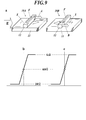
- FIG. 4 is a perspective view a showing two tunnel magnetoresistive elements having different magnetization directions of the pinned magnetic layer, and graphs b and c showing changes in resistance values of the tunnel magnetoresistive elements.
- FIG. 6 is a circuit diagram b to be processed. It is a block circuit diagram of the biomagnetic measurement system which concerns on the modification of one Embodiment of this invention. It is an example of the equivalent circuit schematic of the TMR module which concerns on the modification of one Embodiment of this invention. It is an example of the equivalent circuit schematic of the TMR module which concerns on the modification of one Embodiment of this invention. It is an example of the equivalent circuit schematic of the TMR module which concerns on the modification of one Embodiment of this invention.
- the magnetic sensor of the present embodiment is configured by combining a plurality of integrated bodies with the integrated body having the circuit configuration shown in FIG. 1 as one unit.
- This integrated body includes a plurality of tunnel magnetoresistive elements 10, 10, 10... Connected in series and parallel, and a capacitor Ca connected in parallel to the plurality of tunnel magnetoresistive elements 10, 10, 10. , And a plurality of tunnel magnetoresistive elements 10, 10, 10... And a fixed resistor Rc connected in series to the capacitor Ca.
- the series-parallel means that a plurality of sets of tunnel magnetoresistive elements 10, 10, 10... Connected in series are connected in parallel, or tunnel magnetoresistive elements 10, 10, 10,. .. a plurality of sets connected in series, or a combination thereof (see FIGS.
- Each tunnel magnetoresistive element 10 includes a pinned magnetic layer 11 whose magnetization direction is fixed, a free magnetic layer 12 whose magnetization direction changes under the influence of an external magnetic flux, and a pinned magnetic layer 11 and a free magnetic layer. 12 has an insulating layer 13 disposed between the two.
- Each tunnel magnetoresistive element 10 changes the current flowing from the pinned magnetic layer 11 to the free magnetic layer 12 according to the angular difference between the magnetization direction of the pinned magnetic layer 11 and the magnetization direction of the free magnetic layer 12. Therefore, the resistance value of the tunnel magnetoresistive element 10 changes.
- the magnetization directions of the pinned magnetic layers of all the elements coincide with each other. However, it is only necessary that the magnetization directions are aligned within a range that does not hinder measurement of biomagnetism.
- the magnetization directions of the free magnetic layers 12 in a state where the magnetic fields of the plurality of tunnel magnetoresistive elements 10, 10, 10... are not applied substantially coincide with each other.
- the magnetization directions of the free magnetic layers in the state where no magnetic field is applied to all the elements coincide with each other. However, if the magnetization directions are generally aligned within a range that does not hinder biomagnetism measurement. Good. In the circuit configuration shown in FIG.
- the electrode 1 is connected to the high potential side of the constant voltage source 20, the electrode 2 is connected to the ground, and the potential of the electrode 3 is output as a detection signal. Because the resistance value of the tunnel magnetoresistive elements 10, 10, 10... Changes due to the influence of the magnetic field, the potential of the electrode 3 changes. Therefore, by detecting this, the magnetic field can be detected. As described above, since many tunnel magnetoresistive elements are connected with the same magnetization direction, individual differences among individual elements are absorbed, shot noise is reduced, and the resistance value is dispersed by increasing the number of elements. Thus, heat generation is suppressed and thermal noise is reduced. This is related to noise reduction from the inside, and environmental noise is further reduced as follows.
- a magnetic sensor is configured by combining a plurality of the above-described integrated bodies.
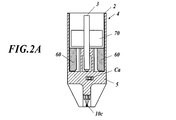
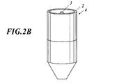
- An example of an integrated unit on which an integrated body is mounted in order to easily realize the combination is shown in the sectional view of FIG. 2A and the perspective view of FIG. 2B.
- the plurality of tunnel magnetoresistive elements 10, 10, 10,... are configured as an integrated circuit on the chip 10C, and the chip 10C and the capacitor Ca are mounted on the same substrate 5.
- One end of the capacitor Ca is electrically connected to the terminal 60, and the other end of the capacitor Ca is electrically connected to the electrode 3 as an output signal terminal.
- the terminal 60 is connected to the electrode 2 as a ground connection terminal through a metal layer formed on the inner surface of the integrated unit 4.
- the upper part of the integrated unit 4 is formed in a cylindrical shape, a metal layer connected to the terminal 60 is formed on the inner peripheral surface thereof, and the electrode 2 is formed on the upper edge of the integrated unit 4.
- An electrode 3 is provided at the center of the upper cylinder of the integrated unit 4, and a circular insulator 70 having an opening is inserted between the metal layer and the electrode 3 so that the electrode 3 penetrates the opening.
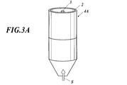
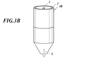
- the direction of magnetization of the pinned magnetic layer 11 of the tunnel magnetoresistive elements 10, 10, 10,... Formed on the chip 10C is indicated by an arrow S in FIGS.
- the chips 10C are mounted in opposite directions to constitute two types of integrated units 4A (FIG. 3A) and integrated unit 4B (FIG.
- the integrated unit 4A and the integrated unit 4B are connected in series and combined as shown in a or b of FIG.
- the integrated unit 4A and the integrated unit 4B are connected and combined in parallel.
- the assembly unit 6 as shown in FIG. 5 holds the combined relative positions of the integrated unit 4A and the integrated unit 4B and fixes them at a predetermined interval.
- the assembly units 6, 6, 6... On which the integrated unit 4A and the integrated unit 4B are mounted are inserted into the insertion portions 7a, 7a, 7a.
- the insertion portions 7a, 7a are connected by a stretchable joint 7b, and as shown in FIG. 6, the assembly units 6, 6, 6... Along the surface of the human body to be detected (for example, the head).
- the placement surface is curved.
- the holding grid 7 mounted with the integrated unit is built in the helmet-shaped magnetic shield device 8 as shown in FIG.
- the biomagnetism detection is performed by mounting the head on the subject's head.
- the inner surface of the appliance 8 is configured such that the head hits the holding grid 7 directly or via a flexible inclusion such as a cloth. This is because the pressing force of the head is applied to the holding grid 7 so that the holding grid 7 is curved along the skull.
- the magnetization direction F of the free magnetic layer 12 in a state where no magnetic field is applied is different from the magnetization direction S of the pinned magnetic layer 11. In FIG. 9a, it is different by 90 degrees. In FIG. 9a, the magnetization direction F of the free magnetic layer 12 related to one tunnel magnetoresistive element 10A is opposite to the magnetization direction F of the free magnetic layer 12 related to the other tunnel magnetoresistive element 10B. However, this may be in the same direction. 9A, the free magnetic layer 12 is shown on the upper side and the fixed magnetic layer 11 is shown on the lower side. However, the present invention is not limited to this, and the free magnetic layer 12 and the fixed magnetic layer 11 are shown in FIG. A mode opposite to a may be used.
- the magnetization direction F of the free magnetic layer 12 related to one tunnel magnetoresistive element 10A fluctuates in the direction of arrow A, and the other The magnetization direction F of the free magnetic layer 12 related to the tunnel magnetoresistive element 10B swings in the direction of arrow B.
- the direction A in which the magnetization direction F of the free magnetic layer 12 swings is the same as the magnetization direction S of the pinned magnetic layer 11.
- the direction B in which the magnetization direction F of the free magnetic layer 12 swings is opposite to the magnetization direction S of the pinned magnetic layer 11.
- the resistance value decreases when the magnetization direction F of the free magnetic layer 12 swings in the same direction as the magnetization direction S of the pinned magnetic layer 11, and the resistance value increases when it swings in the opposite direction. Therefore, the resistance value of the tunnel magnetoresistive element 10A decreases as shown in FIG. 9b, and the resistance value of the tunnel magnetoresistive element 10B increases as shown in c of FIG.
- the resistance value of the tunnel magnetoresistive element 10 changes in a predetermined range (for example, 200 ⁇ to 1 k ⁇ ) according to the strength of the magnetic field H. If the magnetic field H applied to the tunnel magnetoresistive element 10A and the tunnel magnetoresistive element 10B is the same, the fluctuation width of the resistance value is the same, and the combined resistance value does not change and shows a constant value. In this way, this is configured so that the combined resistance of the assembly unit 6 does not change when the magnetic field acting on the tunnel magnetoresistive element 10 in the assembly unit 6 is the same. Based on the above principle, the assembly unit 6 functions as one magnetic sensor having a function of canceling noise such as an external magnetic field.
- the resistance value indicated by one element (10A) and the other element (10B) is as described above. Since the signs are different and the absolute values are equal, it can be prevented from being output as a magnetic detection signal by canceling.
- the weak magnetic field radiated from the detection target for example, the brain
- FIGS. 10 As shown in a1 of FIG. 10, a case where a configuration in which the tunnel magnetoresistive element 10m and the tunnel magnetoresistive element 10n are arranged is a basic element of the magnetic sensor will be described.
- the tunnel magnetoresistive element 10m and the tunnel magnetoresistive element 10n are arranged close to each other with a predetermined interval in the stacking direction of the pinned magnetic layer 11 and the free magnetic layer 12.
- the pinned magnetic layer 11 and the free magnetic layer 12 are arranged on the same plane and arranged close to each other with a predetermined interval. The same effect can be obtained even if they are spaced apart.
- the magnetization direction S of the pinned magnetic layer 11 of one tunnel magnetoresistive element 10m has a relative angle of 180 degrees to the magnetization direction S of the pinned magnetic layer 11 of the other tunnel magnetoresistive element 10n, and is opposite to each other. It has become.
- a1 of FIG. 10 a state where no magnetic field is applied is shown.
- the magnetization direction F of the free magnetic layer 12 intersects the magnetization direction S of the pinned magnetic layer 11 by 90, and the magnetization direction F of the free magnetic layer 12 related to one of the tunnel magnetoresistive elements 10m
- the magnetization direction F of the free magnetic layer 12 related to the other tunnel magnetoresistive element 10n is the same direction. This may be in the reverse direction.
- the relative angle of the magnetization directions of the two tunnel magnetoresistive elements 10m and 10n is 180 degrees, it is not only 180 degrees, but also from 180 degrees to slightly within a range that can be regarded as substantially equivalent to 180 degrees. It may be shifted. Specifically, an angle in the range of up to about 180 degrees ⁇ 3 degrees can be considered to be substantially 180 degrees.
- FIG. 10e shows the combined resistance of a circuit in which the tunnel magnetoresistive element 10m and the tunnel magnetoresistive element 10n are connected in series or in parallel to a3, b3, c3 and d3.
- FIG. 11 shows a view similar to FIG. However, in c1 of FIG. 11, there is a minute magnetic field Hs that has a relatively large influence on the tunnel magnetoresistive element 10m.
- the minute magnetic field Hs corresponds to a magnetic field emitted from a brain or the like to be detected.
- the magnetic field indicated by a1 in FIG. 11 is not generated, even if a large magnetic field H that does not affect the elements 10m and 10n is generated as shown in b1 in FIG. 11, the combined resistance does not change and remains constant. is there.
- the resistance value of the element 10m changes as shown at c2 in FIG.
- the resistance value hardly changes as indicated by c3 in FIG.
- the magnetic field H that is, the large magnetic field existing in the natural world, or the magnetic field radiated from the human body part (for example, the heart) outside the detection target
- the magnetic field Hs that is, the detection target living body.
- Magnetic signals can be detected.
- the plurality of integrated bodies are arranged with a relative angle of 180 degrees in the magnetization direction of the pinned magnetic layer.
- the present invention is not limited to this. It is only necessary that the magnetization direction be arranged with a relative angle exceeding 90 degrees.
- the integrated units 4, 4, 4,... Held in the assembly unit 6 are arranged in a direction away from the surface of the living body part to be detected.
- the integrated unit 4 arranged closest to the detection target and the second, third integrated units 4, 4, 4... Are arranged in the direction away from the integrated unit 4, these integrated units 4, 4 are arranged.
- 4... Are arranged at the same depth as the detection target. That is, when it is desired to detect a magnetic flux at a depth of 30 mm from the living body surface, the distance between the first integrated unit 4 and the second integrated unit 4 is set to 30 mm.
- the third integrated unit 4 and the fourth integrated unit 4 apart from each other, it is possible to detect the magnetic flux in the deep portion corresponding to the distance between the integrated units 4, 4, 4,.
- a number of assembly units 6 that hold the integrated units 4, 4, 4,... Corresponding to the depth direction are further arranged in a grid along the surface of the living body as shown in FIGS. Be placed. Thereby, the magnetic field to be detected can be captured three-dimensionally.
- the output electrodes 3 of the integrated units 4, 4, 4,... Are connected to the arithmetic device 100, and the output signals of the integrated units 4, 4, 4,.
- the arithmetic device 100 converts the input signal into digital data, and calculates the three-dimensional position of the biomagnetic signal source (the position along the skull and the depth direction of the head) and the intensity of the biomagnetism. To generate data representing For example, the arithmetic device 100 generates biomagnetic data representing a three-dimensional magnetic field distribution, and graphicizes this on an output device such as a display for display output. With the above configuration, the biomagnetic measurement system 200 is realized.
- FIGS. 5 to 7 are examples applied to the detection of the cerebral magnetic field, but the biological part to be detected is not limited to this.
- the configurations shown in FIGS. 5 to 7 assume a non-invasive configuration in which the most advanced integrated unit 4 facing the living body is in close contact with the surface of the living body. Regardless of this, the tip in which the integrated unit 4 is built may be formed into an ultrafine needle shape and inserted invasively into the living body, or the living body may be punctured.
- the capacitor Ca connected in parallel to the tunnel magnetoresistive elements 10, 10, 10... Is for cutting off high frequency environmental noise from the output electrode 3.
- the following configuration conditions are effective for this. That is, when the total resistance of the tunnel magnetoresistive elements 10, 10, 10... In parallel with the capacitor Ca in the state where no magnetic field is applied is R [ ⁇ ] and the capacitance of the capacitor Ca is C [F], 4 0.0 ⁇ 10 ⁇ 5 ⁇ C ⁇ R [ ⁇ ⁇ F] ⁇ 4.0 ⁇ 10 ⁇ 4 is satisfied.
- the cutoff frequency is defined by the following equation 1.
- f 1 / (2 ⁇ RC) (Formula 1)
- the maximum value of the magnetic signal of the biological system exists in the range of about 400 [Hz] to 2 [kHz].
- the frequency band above this upper limit is preferably removed as noise, but if the cut-off frequency is set to the upper limit value 2 [kHz] or in the vicinity thereof, a necessary signal may be distorted. Therefore, in the present embodiment, the upper limit value of the cut-off frequency that can sufficiently suppress noise and reliably avoid the occurrence of signal distortion is set to 4 [kHqz].
- the tunnel magnetoresistive element 10 and the capacitor Ca are preferably mounted on the same substrate.
- the substrate any one of a glass epoxy substrate, a polyimide substrate, a ceramic substrate, and a glass substrate is selected and applied, and the wiring on the substrate is a wiring made of a conductive material that does not contain a magnetic material. Apply. For example, as the wiring, a Cu layer with Au plating is applied, and a magnetic layer such as Ni is not provided. This is to avoid the influence of biomagnetism on the detection signal.
- the resistance value of the fixed resistor Rc is preferably a resistance value of 0.4R or more and 2.5R or less.
- the tunnel magnetoresistive element changes its resistance value under the influence of a magnetic field.
- the output V can detect a change in the magnetic field in which the tunnel magnetoresistive element TMR is placed.
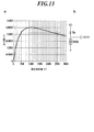
- FIG. 13a shows the characteristic of the change ⁇ V of the output V with respect to the resistance value of the fixed resistor Rc when the resistance value of the tunnel magnetoresistive element TMR changes 0.01% in the circuit shown in FIG. 13b.
- the output difference before and after the change when the resistance value changes by 0.01% is ⁇ V.
- the resistance value of the fixed resistor Rc is 1000 [ ⁇ ]
- the output difference ⁇ V takes a substantially maximum value.
- the resistance value of the fixed resistor Rc is one time the resistance value of the initial tunneling magneto-resistance element TMR.
- the resistance value of the fixed resistor Rc is 400 [ ⁇ ] to 2500 [ ⁇ ], that is, in the range of 0.4 to 2.5 times the resistance value of the initial tunnel magnetoresistive element TMR, the output difference ⁇ V is the maximum value.
- the resistance value R of the fixed resistor Rc is 0.4 R or more and 2.5 R or less with respect to the resistance value R of the tunnel magnetoresistive elements 10, 10, 10. It is preferable to do. Thereby, the detection signal of biomagnetism can be taken out with a big change.
- the high-frequency signal is cut off by the capacitor Ca arranged in parallel with the fixed resistor Rc arranged in series as described above, and further derived from the magnetic field outside the detection target having the same frequency as the living body.
- a high-accuracy biomagnetism measurement system can be realized by canceling out the above signal with two or more tunnel magnetoresistive elements (10A and 10B in FIG. 9, 10m and 10n in FIGS. 10 and 11). Since the tunnel magnetoresistive element is a fine sensor, it can be miniaturized, and as described above, the tunnel magnetoresistive element can be arranged with high density two-dimensionally or three-dimensionally with respect to a living body using a large number of units. In addition, the spatial resolution is improved and high accuracy is achieved in that sense.
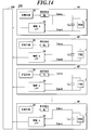
- the biomagnetic measurement system 200 may further include a preamplifier unit 30 including an amplifier circuit and a low-pass filter circuit (LPF) in the above-described integrated body (this is the integrated body in FIG. 14). 40). That is, the integrated body 40 may include the TMR module 1, the fixed resistor Rc, the constant voltage source 20, the preamplifier unit 30, and the capacitor Ca as shown in FIG.
- the TMR module 1 is composed of a plurality of tunnel magnetoresistive elements 10, 10, 10... Connected in series and parallel as described in FIG. In the integrated body 40, as shown in FIG. 14, the TMR module 1 and the capacitor Ca are connected in parallel.
- a constant voltage source 20 is connected to one end side of the TMR module 1 and the capacitor Ca through a fixed resistor Rc.
- the connecting electrical conductors (Line-a, Line-b) at both ends of the TMR module 1 and the capacitor Ca are connected to the input of the preamplifier unit 30.
- a plurality of such integrated bodies 40 are provided, and the output of the preamplifier unit 30 of each of the integrated bodies 40, 40, 40... Is connected to the input of the arithmetic unit 100, and the biomagnetic measurement system 200 is configured.
- the TMR modules 1, 1, 1,... Of each integrated body 40, 40, 40,... Are arranged with respect to a living body (for example, the head or chest of a human body), and magnetic signals from the living body are transmitted.
- the output signal of the preamplifier unit 30 corresponding to each TMR module 1 is input to the arithmetic device 100, and the arithmetic device 100 calculates and estimates the position and strength of the biomagnetic signal source based on the output signal.
- At least the TMR module 1 and the capacitor Ca are mounted on the same substrate as described above.
- the substrate any one of a glass epoxy substrate, a polyimide substrate, a ceramic substrate, and a glass substrate is selected and applied, and the wiring on the substrate is a wiring made of a conductive material that does not contain a magnetic material. Apply.
- a Cu layer with Au plating is applied, and a magnetic layer such as Ni is not provided. This is to avoid the influence of biomagnetism on the detection signal.
- the TMR module 1 includes a plurality of tunnel magnetoresistive elements 10 connected in series or parallel to each other as shown in FIGS. 15A to 15C, for example, when the tunnel magnetoresistive element 10 is shown as one resistor. Is done.
- the TMR module 1 illustrated in FIG. 15A has a configuration in which tunnel magnetoresistive elements 10 connected in series are connected in parallel.
- the TMR module 1 shown in FIG. 15B has a configuration in which the configurations in which the tunnel magnetoresistive elements 10 are connected in series are connected in parallel, and the configurations formed thereby are further connected in series.
- a TMR module 1 shown in FIG. 15C has a configuration in which tunnel magnetoresistive elements 10 connected in parallel are connected in series.
- connection method is not limited, shot noise and quantization noise are reduced as a whole by connecting the tunnel magnetoresistive element 10 in parallel, and the TMR module is connected by connecting the tunnel magnetoresistive element in series. As a whole, thermal noise and quantization noise are reduced.
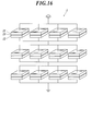
- the tunnel magnetoresistive element 10 includes a pinned magnetic layer 11 (or 12) whose magnetization direction is fixed, a free magnetic layer 12 (or 11) whose magnetization direction changes under the influence of an external magnetic flux, and
- the insulating layer 13 is disposed between the pinned magnetic layer and the free magnetic layer, and the insulating layer 13 has a tunnel effect according to an angular difference between the magnetization direction of the pinned magnetic layer and the magnetization direction of the free magnetic layer.
- action which changes resistance (refer FIG. 16).
- the amplitude on the connecting electrical conductors (Line-a, Line-b) is drastically reduced, and the electromagnetic coupling from the connecting electrical conductors (Line-a, Line-b) to the surroundings is reduced, and the subsequent first stage amplifier circuit Since the gain can be increased, the dynamic range is increased, the signal accuracy in the preamplifier system is improved, and the noise reduction effect by the low-pass filter (LPF) is also increased.
- LPF low-pass filter
- the integrated body 40 shown in FIG. 14 includes a tunnel magnetoresistive module including a tunnel magnetoresistive element that detects a biomagnetic signal, and a capacitor that temporarily receives the output of the tunnel magnetoresistive module and outputs it to a subsequent circuit.
- the tunnel magnetoresistive module and the capacitor are mounted on the same substrate, the resistance value of the tunnel magnetoresistive module in a state where no magnetic field is applied is R [ ⁇ ], and the capacitance of the capacitor is C [F].
- R [ ⁇ ] resistance value of the tunnel magnetoresistive module in a state where no magnetic field is applied
- C [F] the capacitance of the capacitor
- the resistance value of the fixed resistor Rc is preferably set to a resistance value of 0.4R or more and 2.5R or less (R is a state in which the magnetic field of the TMR module 1 is not applied). Resistance value).
- the output V that changes with the resistance value of the tunnel magnetoresistive element 10 is 0.4R or more. This is because when it is 5R or less, the output difference ⁇ V exceeds about 80% of the maximum value, and a minute change in resistance value of the tunnel magnetoresistive element TMR is transmitted with a large output difference ⁇ V.
- FIGS. 17 to 21 the modification of the present embodiment is not limited to that shown in FIG. 14, and the same operational effects can be obtained with the circuit configurations shown in FIGS. 17 to 21.
- Ca1 to Ca4 are applied as capacitors.
- the electrode 50 is grounded.
- two sets (Ca1, Ca2) of the TMR module 1 and the capacitor are connected, and the connection line to the preamplifier unit 30 immediately before the TMR module 1 and the capacitor Ca1 in the subsequent stage and the fixed resistor Rc,
- the TMR module 1 and the capacitor Ca2 connected in parallel may be connected.
- a plurality of TMR modules 1 (FIGS. 19 to 21) or TMR modules 1 and resistors (FIG. 18) are arranged as in the circuits shown in FIGS.
- a circuit may be configured.
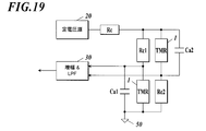
- the circuits of FIGS. 19 to 20 constitute a circuit such as a Wheatstone bridge, it is possible to accurately detect a signal change with a simple circuit configuration.
- FIG. 19 when one TMR module 1 and three resistors Rc1 to Rc3 form a bridge, the number of TMR modules 1 is small, so that there is an advantage that a circuit can be easily manufactured.
- a bridge is constituted by four TMR modules 1, and a capacitor Ca1 is arranged so as to connect intermediate points. Even if it does in this way, before inputting into the preamplifier part 30, the output noise of the TMR module 1 can suppress the environmental noise of a high frequency band by the capacitor
- the medical field it can be used as a magnetic sensor and biomagnetic measurement system for measuring the magnetism of a living body.
Landscapes
- Health & Medical Sciences (AREA)
- Life Sciences & Earth Sciences (AREA)
- Physics & Mathematics (AREA)
- Surgery (AREA)
- General Health & Medical Sciences (AREA)
- Engineering & Computer Science (AREA)
- Biomedical Technology (AREA)
- Heart & Thoracic Surgery (AREA)
- Medical Informatics (AREA)
- Molecular Biology (AREA)
- Biophysics (AREA)
- Animal Behavior & Ethology (AREA)
- Pathology (AREA)
- Public Health (AREA)
- Veterinary Medicine (AREA)
- Condensed Matter Physics & Semiconductors (AREA)
- General Physics & Mathematics (AREA)
- Measurement And Recording Of Electrical Phenomena And Electrical Characteristics Of The Living Body (AREA)
- Hall/Mr Elements (AREA)
- Measuring Magnetic Variables (AREA)
Abstract
Description
SQUIDセンサにより生体磁気計測するには、SQUIDセンサを冷媒により超伝導状態に保つ必要がある。そのため、SQUIDセンサは、冷媒が貯留されたデュワに内蔵され、この冷媒に浸漬された状態で計測に用いられる。
このデュワの冷媒槽の外壁部の一部を、生体の計測対象部位、例えば頭蓋に対応した形状に形成し、この外壁部の内側に多数のSQUIDセンサを配列させて冷媒に浸漬し、外壁部の外側を生体に接触させることにより、多数のSQUIDセンサを生体に対して一定の距離に近接させて計測し、脳磁図等を得ることができる生体磁気計測装置が提案されている。
生体磁気信号の信号強度は10-10~10-15Tのオーダーであるが、大きな外部磁場(雑磁場)は非常に大きく、例えば都市の磁気ノイズは10-7T、地磁気は10-5Tといったオーダーであり、同時にセンシングした場合、生体由来の信号はこれらの雑磁場によってかき消されてしまう。
そこで雑磁場のない環境で計測を行うため、磁気シールドルームなどが提案されている。
また外部磁場を取り除く目的で、SQUIDを用いた生体磁気検出装置ではグラジオメータなどが提案されている。
グラジオメータは、間隔をあけて配置された2つのピックアップコイルを有しており、例えば特許文献6-8に記載されている。
そこで本願発明者は、常温で使用可能で、小型軽薄化、高密度化等が可能なセンサデバイスとして、トンネル磁気抵抗素子(TMR(Tunnel Magneto Resistive)素子)を生体磁気の計測に適用することを考える。
トンネル磁気抵抗素子を磁気センサとして採用することで磁気センサの高密度化等を進めることができるが、上述の外部磁場等の問題を解決する必要がある。
前記集積体は、前記固定磁性層の磁化の向き及び磁場のかからない状態での前記フリー磁性層の磁化の向きをそれぞれ実質的に一致させた配置で直並列に接続された複数の前記トンネル磁気抵抗素子と、当該直並列に接続された複数の前記トンネル磁気抵抗素子に並列に接続されたコンデンサと、前記直並列に接続された複数の前記トンネル磁気抵抗素子及び前記コンデンサに対して直列に接続された固定抵抗とから構成され、
複数の前記集積体同士が前記固定磁性層の磁化の向きを90度を超える相対角をもって配置されて直列及び/又は並列で接続された磁気センサである。
本集積体は、直並列に接続された複数のトンネル磁気抵抗素子10,10,10・・・と、複数のトンネル磁気抵抗素子10,10,10・・・に並列に接続されたコンデンサCaと、複数のトンネル磁気抵抗素子10,10,10・・・及びコンデンサCaに対して直列に接続された固定抵抗Rcとから構成される。ここで、直並列とは、直列に接続されたトンネル磁気抵抗素子10,10,10・・・を複数組並列に接続すること、又は並列に接続されたトンネル磁気抵抗素子10,10,10・・・を複数組直列に接続すること、またはこれらを組み合わせたものを言う(図15A~図15C参照)。
各トンネル磁気抵抗素子10は、磁化の向きが固定された固定磁性層11、外部からの磁束の影響を受けて磁化の向きが変化するフリー磁性層12、及び、固定磁性層11及びフリー磁性層12との間に配置された絶縁層13を有する。
各トンネル磁気抵抗素子10は、固定磁性層11の磁化の向きとフリー磁性層12の磁化の向きとの角度差に従って固定磁性層11からフリー磁性層12に流れる電流を変化させる。したがって、トンネル磁気抵抗素子10の抵抗値が変化する。
同一集積体においては、複数のトンネル磁気抵抗素子10,10,10・・・の固定磁性層11の磁化の向きは実質的に互いに一致している。全ての素子の固定磁性層の磁化の向きが互いに一致しているのが理想的であるが、生体磁気の測定に支障のない範囲で概ね磁化の向きが揃っていればよい。
また、同一集積体においては、複数のトンネル磁気抵抗素子10,10,10・・・の磁場のかからない状態でのフリー磁性層12の磁化の向きは実質的に互いに一致している。全ての素子の磁場のかからない状態でのフリー磁性層の磁化の向きが互いに一致しているのが理想的であるが、生体磁気の測定に支障のない範囲で概ね磁化の向きが揃っていればよい。
図1に示す回路構成において、電極1は、定電圧源20の高電位側に接続され、電極2はグランドに接続され、電極3の電位は検出信号として出力される。磁界の影響によりトンネル磁気抵抗素子10,10,10・・・の抵抗値が変化することで、電極3の電位が変化するため、これを検出することで磁界を検出することができる。
以上のように多数のトンネル磁気抵抗素子が磁化の向きを同一にして接続されるので、個々の素子の個体差が吸収されショットノイズが低減され、素子が多数になることにより、抵抗値が分散され、熱の発生が抑制されて熱ノイズが低減される。これは内部由来のノイズ低減に関することであり、環境ノイズに関してはさらに以下のようにして低減する。
図2A、図2Bに示す集積ユニット4においては、チップ10Cに上述の複数のトンネル磁気抵抗素子10,10,10・・が集積回路として構成され、チップ10CとコンデンサCaとが同一基板5に実装されている。
コンデンサCaの一端は端子60に電気的に接続され、コンデンサCaの他端は出力信号端子としての電極3に電気的に接続されている。端子60は集積ユニット4の内面に形成された金属層を通じてグランド接続端子としての電極2に接続されている。集積ユニット4の上部は円筒状に形成されており、その内周面に端子60に接続する金属層が形成され、集積ユニット4の上端縁に電極2が形成されている。集積ユニット4の上部の円筒中央には電極3が設けられており、金属層と電極3との間に、開口を有する円形の絶縁体70が、その開口を電極3が貫くようにはめ込まれている。
チップ10Cに構成されるトンネル磁気抵抗素子10,10,10・・の固定磁性層11の磁化の向きを図3A、図3Bにおいて矢印Sで示す。
このチップ10Cを相互逆向きに実装して固定磁性層11の磁化の向きSが相互に反対向きにされた2種の集積ユニット4A(図3A)、集積ユニット4B(図3B)を構成する。
そして、複数の集積ユニットを接続することで、図4のa又はbに示すように集積ユニット4Aと集積ユニット4Bとを直列に接続して組み合わせる。又は、図4のcに示すように集積ユニット4Aと集積ユニット4Bとを並列に接続して組み合わせる。
それとともに、組み合わされた集積ユニット4Aと集積ユニット4Bとの相対位置を図5に示すような組立ユニット6に保持させて所定の間隔を隔てて固定する。
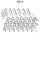
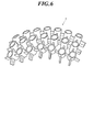
同様に集積ユニット4A及び集積ユニット4Bを搭載した組立ユニット6,6,6・・・を保持グリッド7の挿入部7a,7a,7a・・・に挿入して縦横に配置し保持する。但し、挿入部7a,7a間は伸縮性のジョイント7bで連結されており、図6に示すように検出対象の人体の表面(例えば頭部)に沿って組立ユニット6,6,6・・・の配置面が湾曲する。
脳磁界を検出対象とする場合は、頭部に装着するために、図7に示すように集積ユニット実装済みの保持グリッド7をヘルメット型の磁気シールド装具8に内蔵し、図8に示すように被検者の頭部に装着させて生体磁気検出を実行する。もちろん、装具8の内面にあっては、頭部が保持グリッド7に直接又は布等の柔軟な介在物を介して当たるように構成される。頭部の押圧力が保持グリッド7に加わって保持グリッド7が頭蓋に沿って湾曲するようにするためである。
すなわち、図9のaに示すように、一方のトンネル磁気抵抗素子10Aの固定磁性層11の磁化の向きSは、他方のトンネル磁気抵抗素子10Bの固定磁性層11の磁化の向きSと180度の相対角を有して相互逆向きとなっている。
図9のaにおいては、磁場のかからない状態でのフリー磁性層12の磁化の向きを矢印Fで表示している。磁場のかからない状態でのフリー磁性層12の磁化の向きFは、固定磁性層11の磁化の向きSと異なる方向とされる。図9のaにおいては90度異なる。
図9のaにおいては、一方のトンネル磁気抵抗素子10Aに係るフリー磁性層12の磁化の向きFと、他方のトンネル磁気抵抗素子10Bに係るフリー磁性層12の磁化の向きFとが逆向きとなっているが、これは同方向でもよい。また、図9のaにおいては、フリー磁化層12を上側に固定磁化層11を下側に図示しているが、これに限るものではなく、フリー磁化層12と固定磁化層11が図9のaとは逆の態様でも構わない。
このとき、トンネル磁気抵抗素子10Aにおいては、フリー磁性層12の磁化の向きFが振れる方向Aは、固定磁性層11の磁化の向きSと同方向である。トンネル磁気抵抗素子10Bにおいては、フリー磁性層12の磁化の向きFが振れる方向Bは、固定磁性層11の磁化の向きSと反対方向である。
トンネル磁気抵抗素子10において、フリー磁性層12の磁化の向きFが固定磁性層11の磁化の向きSと同方向に振れると、抵抗値は下がり、反対方向に振れると抵抗値が上がる。
したがって、図9のbに示すようにトンネル磁気抵抗素子10Aの抵抗値は下がり、図9のcに示すようにトンネル磁気抵抗素子10Bの抵抗値は上がる。トンネル磁気抵抗素子10の抵抗値は、磁界Hの強さに従って所定の範囲(例えば200Ωから1kΩ)で変化する。トンネル磁気抵抗素子10Aとトンネル磁気抵抗素子10Bとに掛かる磁界Hが同一であれば、抵抗値の振れ幅は同一となり、合成抵抗値は変化せず一定の値を示す。このように、組立ユニット6内のトンネル磁気抵抗素子10に作用する磁界が同一のときに組立ユニット6の合成抵抗が変化しないようにこれを構成する。
以上の原理によって組立ユニット6は外部磁界等のノイズを相殺する機能を有した一つの磁気センサとして機能する。
一方、検出対象(たとえば脳)から放射される微弱な磁界については、磁束密度/磁界の大きさが異なるために、組立ユニット6内の異なる集積ユニット4Aと4Bに対して、異なった作用を与える。すなわち、一方の抵抗値変化が大きく、他方の抵抗値変化が小さいといった不均衡が生じる。多数の集積ユニットを接続している場合も同様に、抵抗値変化が大きく発生する集積ユニットと小さく発生する集積ユニットが生じる。
したがって、集積体を組み合わせたセンサから近い微弱な磁束に対しては、双方の集積体が出力する抵抗値の絶対値が異なることとなり、この総和となる磁気検出信号はゼロから変化する。そして上記した通り、ノイズとなる大きな磁界はキャンセルされているので、検出目的の微小磁界のみを磁気検出信号として取り出すことが可能になる。
なお、2つのトンネル磁気抵抗素子10mと10nの磁化の向きの相対角を180度とする場合、丁度180度とするだけでなく、実質的に180度と同等とみなせる範囲で180度から僅かにずれていてもよい。具体的には、180度±3度程度までの範囲の角度であれば実質的には180度であるとみなすことができる。
図10のb1、c1、d1に示すように、方向が異なる大きな磁界H1,H2,H3が生じると、フリー磁性層12の磁化の向きFはそれぞれ異なった振れ方をするが、その抵抗値は相反する変化をしており、合成抵抗が一定となる。これがノイズとなる大きな磁界をキャンセルする原理である。
図11のa1に示す磁界が生じていない場合に対し、図11のb1に示すように素子10m、10nに対して影響が異ならない大きな磁界Hが生じても、合成抵抗は変化せず一定である。図10で確認したように磁界Hが如何なる方向であっても同様である。このような状況下で、図11のc1に示すように素子10mの位置に微小磁界Hsが生じると、図11のc2に示すように素子10mの抵抗値は変化するが、離れた位置にある素子10nでは微小磁界Hsの影響がほとんど無く、図11のc3に示すように抵抗値がほとんど変化しない。このようにして、磁界H、すなわち、自然界に存在する大きな磁界や、検出対象外の人体の部位(例えば心臓)から広範に放射される磁界をキャンセルしつつ、磁界Hs、すなわち、検出対象の生体磁気信号を検知することができる。なお、上述した実施形態においては、複数の集積体同士を、固定磁性層の磁化の向きを実質的に180度の相対角をもって配置しているが、これに限るものではなく、固定磁性層の磁化の向きが90度を超える相対角を持って配置されていればよい。
このように配置することで、生体部位表面から深さ方向の磁界を検出することが可能となる。
検出対象に最も近接配置した集積ユニット4と、その集積ユニット4から遠ざかる方向に第二、第三の集積ユニット4,4,4・・・を配置していく場合、これらの集積ユニット4,4,4・・・の間隔は検出対象の深さと同等に配置する。すなわち、生体表面から30mmの深部の磁束を検出したい場合、第一の集積ユニット4と第二の集積ユニット4の距離を30mmにして配置する。さらに第三の集積ユニット4、第四の集積ユニット4と離して配置することで、集積ユニット4,4,4・・・の距離に対応した深部の磁束を検出することができる。
以上のように深さ方向に対応して集積ユニット4,4,4・・・を保持する組立ユニット6が、さらに図5~図7にも示すように、生体表面に沿ってグリッド状に多数配置される。これにより、検出対象の磁界を3次元的に捕えることができる。各集積ユニット4,4,4・・・の出力電極3が演算装置100に接続されて、集積ユニット4,4,4・・・の出力信号が演算装置100に入力される。演算装置100は、入力された信号をデジタルデータに変換するとともに、演算によって生体磁気の信号源の3次元的な位置(頭蓋に沿う方向及び頭部の深さ方向における位置)や生体磁気の強度等を表すデータを生成する。例えば、演算装置100は、3次元の磁界分布を表わす生体磁気データを生成し、これをディスプレイ等の出力装置に対してグラフィック化して表示出力する。以上の構成により、生体磁気計測システム200が実現される。
すなわち、コンデンサCaと並列のトンネル磁気抵抗素子10,10,10・・・の磁界のかからない状態での抵抗の合計値をR〔Ω〕、コンデンサCaの容量をC〔F〕とするとき、4.0×10⁻⁵<C・R〔Ω・F〕<4.0×10⁻⁴を満たすことを構成条件とする。
f=1/(2πRC)・・・(式1)
生体系の磁気信号の最大値は、400〔Hz〕~2〔kHz〕程度に存在する。この上限以上の周波数帯域はノイズとして除去することが好ましいが、カットオフ周波数を上記上限値2[kHz]又はその近傍に設定すると、必要な信号が歪んでしまう恐れがある。そこで、本実施形態においては、ノイズを十分抑制することができ、かつ、信号歪みの発生を確実に回避できるカットオフ周波数の上限値を4[kHqz]としている。
これを式1よりC・Rに置き換えると、次式2のとおりとなる。
4.0×10⁻⁵<C・R〔Ω・F〕<4.0×10⁻⁴・・・(式2)
トンネル磁気抵抗素子の抵抗値Rを1〔kΩ〕と設定する場合、式2を満たすコンデンサの容量値Cは0.04〔μF〕から0.4〔μF〕となる。
C・R〔Ω・F〕=4.0×10⁻⁵としたときと、C・R〔Ω・F〕=4.0×10⁻⁴としたときの定電圧源20(電極1に接続)に対するグランド電極2-出力電極3間の周波数対電圧減衰特性は図12のグラフに示す通りとなる。図12に示すグラフにおいて縦軸は定電圧源20に対する減衰率である。
図12に示すグラフにおいて比較的低周波帯のフラットな最高値から3〔dB〕落ちた周波数をカットオフ周波数とすると、C・R〔Ω・F〕=4.0×10⁻⁵としたときのカットオフ周波数は4〔kHz〕であり、C・R〔Ω・F〕=4.0×10⁻⁴としたときのカットオフ周波数は400〔Hz〕である。なお、図12のグラフは、一例として、固定抵抗Rcの抵抗値を1〔kΩ〕、トンネル磁気抵抗素子10,10,10・・・の抵抗値Rを1〔kΩ〕とした時、コンデンサCaの容量Cの値を変化させて作成したものである。
トンネル磁気抵抗素子は、磁場の影響を受けてその抵抗値を変化させる。図13のbに示す回路において、トンネル磁気抵抗素子TMRの抵抗値が変化すると出力Vが変化するため、この出力Vによってトンネル磁気抵抗素子TMRの置かれる磁場の変化を検出することができる。図13のbに示す回路においてトンネル磁気抵抗素子TMRの抵抗値が0.01%変化した時の出力Vの変化ΔVの固定抵抗Rcの抵抗値に対する特性を図13のaに示した。初期のトンネル磁気抵抗素子TMRの抵抗値を1000〔Ω〕とし抵抗値が0.01%変化するときの変化前と変化後の出力差がΔVである。固定抵抗Rcの抵抗値が1000〔Ω〕であるときに、出力差ΔVはほぼ最大値をとる。このとき、固定抵抗Rcの抵抗値は、初期のトンネル磁気抵抗素子TMRの抵抗値の1倍である。固定抵抗Rcの抵抗値が、400〔Ω〕から2500〔Ω〕、すなわち、初期のトンネル磁気抵抗素子TMRの抵抗値の0.4倍から2.5倍の範囲で出力差ΔVが最大値の約80%を超えており、トンネル磁気抵抗素子TMRの微小な抵抗値の変化を大きな出力差ΔVで伝えていることがわかる。
したがって、集積体におけるトンネル磁気抵抗素子10,10,10・・・の磁界のかからない状態での抵抗値Rに対して、固定抵抗Rcの抵抗値は0.4R以上2.5R以下の抵抗値とすることが好ましい。これにより生体磁気の検出信号を大きな変化で取り出すことができる。
トンネル磁気抵抗素子は微細なセンサであるため、小型化が可能であり、上述したように多数のユニットを使用して生体に対して2次元的さらには3次元的に高密度に配置することができ、空間分解能が向上しその意味でも高精度化が図られる。
上記の生体磁気計測システム200は、図14に示すように、上述の集積体にさらに増幅回路及びローパスフィルター回路(LPF)からなるプリアンプ部30を有する構成としてもよい(これを図14において集積体40として図示する)。即ち、集積体40は、図14に示すように、TMRモジュール1と、固定抵抗Rcと、定電圧源20と、プリアンプ部30と、コンデンサCaとを備えることとしてもよい。TMRモジュール1は、図1で説明した、直並列に接続された複数のトンネル磁気抵抗素子10,10,10・・・により構成される。
集積体40においては、図14に示すようにTMRモジュール1と、コンデンサCaとが並列に接続される。定電圧源20が固定抵抗Rcを介してTMRモジュール1及びコンデンサCaの一端側に接続される。TMRモジュール1及びコンデンサCaの両端の接続電気導線(Line-a、Line-b)がプリアンプ部30の入力に接続される。このような集積体40が複数設けられ、各集積体40,40,40・・・のプリアンプ部30の出力が演算装置100の入力に接続されて、生体磁気計測システム200が構成される。一方、各集積体40,40,40,・・・のTMRモジュール1,1,1,・・・が生体(例えば人体の頭部や胸部など)に対して配置され、生体からの磁気信号を検出する。各TMRモジュール1に対応するプリアンプ部30の出力信号が演算装置100に入力され、演算装置100は、生体磁気の信号源の位置、強さ等を同出力信号に基づき演算して推定する。
図15Aに示すTMRモジュール1は、トンネル磁気抵抗素子10を直列に接続した構成同士を並列に接続した構成である。図15Bに示すTMRモジュール1は、トンネル磁気抵抗素子10を直列に接続した構成同士を並列に接続し、これによりできた構成同士をさらに直列に接続した構成である。図15Cに示すTMRモジュール1は、トンネル磁気抵抗素子10を並列に接続した構成同士を直列に接続した構成である。接続の仕方は問わないが、トンネル磁気抵抗素子10を並列に接続することによりTMRモジュール1全体としては、ショットノイズ、量子化ノイズが低減され、トンネル磁気抵抗素子を直列に接続することによりTMRモジュール1全体としては、熱ノイズ、量子化ノイズが低減される。
図14におけるTMRモジュール1の磁界のかからない状態での抵抗値をRとした場合、TMRモジュール1の両端におけるカットオフ周波数(ここでは、入力信号の周波数を変化させたときの、TMRモジュール1からの出力が十分小さくなったみなすことができる周波数)は上述の式1(f=1/(2πRC))で定義される。上述のように、生体系の磁気信号の最大値は、400〔Hz〕~2〔kHz〕程度に存在するので、ノイズを十分抑制することができ、かつ、信号歪みの発生を確実に回避できるようにカットオフ周波数を400〔Hz〕~4[kHz]とし、これを式1よりC・Rに置き換えると、上記式2(4.0×10-5<C・R〔Ω・F〕<4.0×10-4)となる。C・R〔Ω・F〕=4.0×10-5としたときと、C・R〔Ω・F〕=4.0×10-4としたときの定電圧源20に対するTMRモジュール1の両端部の周波数対電圧減衰特性のシミュレーション結果は、図12に示すグラフと同様となる。
よって、上記構成要件を満たすことにより、上記説明した並列接続のコンデンサCaを含めた簡素な構成によって、例えば、10〔kHz〕で10〔dB〕から30〔dB〕、100〔kHz〕では30〔dB〕から50〔dB〕もの減衰が達成でき、トンネル磁気抵抗素子の出力から高周波の環境ノイズを低減させることができる。
したがって、接続電気導線(Line-a、Line-b)に載る振幅も激減され、接続電気導線(Line-a、Line-b)から周囲に対する電磁結合にノイズ逓減効果とともに、その後の初段増幅回路のゲインを上げることが可能となることでダイナミックレンジが上がりプリアンプ系での信号精度向上が図られるとともに、ローパスフィルタ(LPF)によるノイズの逓減効果も上がる。
図17に示すように、TMRモジュール1及びコンデンサを2組(Ca1、Ca2)接続し、後段のTMRモジュール1及びコンデンサCa1の直前のプリアンプ部30への接続線と固定抵抗Rcとの間に、並列接続されたTMRモジュール1とコンデンサCa2を接続してもよい。
図18~図21に示す回路のように、複数のTMRモジュール1を配置する(図19~図21)か、TMRモジュール1と抵抗とを配置する(図18)ことによって、差動増幅型の回路を構成するようにしてもよい。特に、図19~図20の回路は、ホイートストンブリッジのような回路を構成しているので、簡単な回路構成で正確に信号の変化を検出することができる。図19のように一つのTMRモジュール1と3つの抵抗Rc1~Rc3とでブリッジを構成すると、TMRモジュール1の数が少ないため、回路を作製しやすくなるメリットがある。
図21に示した回路は、4つのTMRモジュール1でブリッジを構成し、中間点を接続するようにコンデンサCa1を配している。このようにしても、プリアンプ部30に入力される前に、TMRモジュール1の出力をコンデンサCa1によって高周波帯域の環境ノイズを抑制することができる。
6 組立ユニット
7 保持グリッド
10 トンネル磁気抵抗素子
11 固定磁性層
12 フリー磁性層
20 コンデンサ
30 固定抵抗
Claims (10)
- 磁化の向きが固定された固定磁性層、外部からの磁束の影響を受けて磁化の向きが変化するフリー磁性層、及び、前記固定磁性層及び前記フリー磁性層との間に配置された絶縁層を有し、前記固定磁性層の磁化の向きと前記フリー磁性層の磁化の向きとの角度差に従って前記固定磁性層から前記フリー磁性層に流れる電流を変化させるトンネル磁気抵抗素子を含む集積体が複数組み合わされた磁気センサであって、
前記集積体は、前記固定磁性層の磁化の向き及び磁場のかからない状態での前記フリー磁性層の磁化の向きをそれぞれ実質的に一致させた配置で直並列に接続された複数の前記トンネル磁気抵抗素子と、当該直並列に接続された複数の前記トンネル磁気抵抗素子に並列に接続されたコンデンサと、前記直並列に接続された複数の前記トンネル磁気抵抗素子及び前記コンデンサに対して直列に接続された固定抵抗とから構成され、
複数の前記集積体同士が前記固定磁性層の磁化の向きを90度を超える相対角をもって配置されて直列及び/又は並列で接続された磁気センサ。 - 前記相対角が実質的に180度である請求項1に記載の磁気センサ。
- 前記複数の集積体が所定の間隔を隔てて配置された請求項1又は請求項2に記載の磁気センサ。
- 前記トンネル磁気抵抗素子は、磁場のかからない状態での前記フリー磁性層の磁化の向きと、前記固定磁性層の磁化の向きとが異なる請求項1から請求項3のうちいずれか一に記載の磁気センサ。
- 前記集積体における前記固定抵抗は、当該集積体において当該固定抵抗に対して直列に接続された複数の前記トンネル磁気抵抗素子の磁界のかからない状態での抵抗値をR〔Ω〕とするとき、0.4R以上2.5R以下である請求項1から請求項4のうちいずれか一に記載の磁気センサ。
- 複数の前記トンネル磁気抵抗素子及び前記コンデンサは同一の基板に実装されており、複数の前記トンネル磁気抵抗素子の磁界のかからない状態での抵抗値をR〔Ω〕、前記コンデンサの容量をC〔F〕とするとき、4.0×10⁻⁵<C・R〔Ω・F〕<4.0×10⁻⁴を満たす請求項1から請求項5のうちいずれか一に記載の磁気センサ。
- 複数の前記トンネル磁気抵抗素子と、前記固定抵抗とが直列にして定電圧源に接続され、前記トンネル磁気抵抗素子と前記固定抵抗との間から検出信号の出力線が取り出されている請求項1から請求項6のうちいずれか一に記載の磁気センサ。
- 前記基板は、ガラスエポキシ基板、ポリイミド基板、セラミック基板、ガラス基板のうちのいずれかであることを特徴とする請求項1から請求項7のうちいずれか一に記載の磁気センサ。
- 前記基板の配線に磁性体が含まれないことを特徴とする請求項1から請求項8のうちいずれか一に記載の磁気センサ。
- 請求項1から請求項9のうちいずれか一に記載の磁気センサを複数備え、当該複数の磁気センサの検出信号に基づき生体磁気情報を生成する演算装置を備える生体磁気計測システム。
Priority Applications (2)
| Application Number | Priority Date | Filing Date | Title |
|---|---|---|---|
| US14/114,972 US8933696B2 (en) | 2011-05-20 | 2012-05-16 | Magnetic sensor and biomagnetism measurement system |
| JP2013516307A JP5861703B2 (ja) | 2011-05-20 | 2012-05-16 | 磁気センサ及び生体磁気計測システム |
Applications Claiming Priority (4)
| Application Number | Priority Date | Filing Date | Title |
|---|---|---|---|
| JP2011-113055 | 2011-05-20 | ||
| JP2011113055 | 2011-05-20 | ||
| JP2011-123990 | 2011-06-02 | ||
| JP2011123990 | 2011-06-02 |
Publications (1)
| Publication Number | Publication Date |
|---|---|
| WO2012161037A1 true WO2012161037A1 (ja) | 2012-11-29 |
Family
ID=47217117
Family Applications (1)
| Application Number | Title | Priority Date | Filing Date |
|---|---|---|---|
| PCT/JP2012/062452 Ceased WO2012161037A1 (ja) | 2011-05-20 | 2012-05-16 | 磁気センサ及び生体磁気計測システム |
Country Status (3)
| Country | Link |
|---|---|
| US (1) | US8933696B2 (ja) |
| JP (1) | JP5861703B2 (ja) |
| WO (1) | WO2012161037A1 (ja) |
Cited By (4)
| Publication number | Priority date | Publication date | Assignee | Title |
|---|---|---|---|---|
| JP2017211258A (ja) * | 2016-05-25 | 2017-11-30 | 三菱電機株式会社 | 生体情報検出装置、生体情報検出センサおよび生体情報検出装置の補正方法 |
| JP2019027786A (ja) * | 2017-07-25 | 2019-02-21 | Tdk株式会社 | 磁場センサ |
| JP2020168138A (ja) * | 2019-04-02 | 2020-10-15 | 株式会社リコー | 磁気計測装置、及び頭部装着型磁気計測装置 |
| US10830840B2 (en) | 2015-12-28 | 2020-11-10 | Konica Minolta, Inc. | Magnetic sensor, sensor unit, magnetic detection device, and magnetic measurement device |
Families Citing this family (23)
| Publication number | Priority date | Publication date | Assignee | Title |
|---|---|---|---|---|
| EP3040734A1 (en) * | 2014-07-17 | 2016-07-06 | Crocus Technology Inc. | Apparatus and method for sensing a magnetic field using subarrays of magnetic field sensing elements for high voltage applications |
| EP3040997A1 (en) * | 2014-07-17 | 2016-07-06 | Crocus Technology Inc. | Apparatus and method for sensing a magnetic field using arrays of magnetic field sensing elements |
| US9766305B2 (en) | 2014-07-17 | 2017-09-19 | Crocus Technology Inc. | Apparatus and method for layout of magnetic field sensing elements in sensors |
| US10401442B2 (en) | 2014-07-17 | 2019-09-03 | Crocus Technology Inc. | Apparatus, system, and method for sensing communication signals with magnetic field sensing elements |
| US9689936B2 (en) | 2014-07-17 | 2017-06-27 | Crocus Technology Inc. | Apparatus and method for sensing a magnetic field using subarrays of magnetic sensing elements |
| US10067201B2 (en) * | 2016-04-14 | 2018-09-04 | Texas Instruments Incorporated | Wiring layout to reduce magnetic field |
| CN109414212B (zh) * | 2016-06-03 | 2023-03-21 | 国立大学法人东京医科齿科大学 | 生物磁测量装置 |
| CN109561848B (zh) * | 2016-08-02 | 2023-03-10 | 国立大学法人东京医科齿科大学 | 生物磁测量装置 |
| US20190061617A1 (en) * | 2017-08-29 | 2019-02-28 | GM Global Technology Operations LLC | Audio Control Systems And Methods Based On Driver Helmet Use |
| WO2019060298A1 (en) | 2017-09-19 | 2019-03-28 | Neuroenhancement Lab, LLC | METHOD AND APPARATUS FOR NEURO-ACTIVATION |
| US11717686B2 (en) | 2017-12-04 | 2023-08-08 | Neuroenhancement Lab, LLC | Method and apparatus for neuroenhancement to facilitate learning and performance |
| US12280219B2 (en) | 2017-12-31 | 2025-04-22 | NeuroLight, Inc. | Method and apparatus for neuroenhancement to enhance emotional response |
| US11478603B2 (en) | 2017-12-31 | 2022-10-25 | Neuroenhancement Lab, LLC | Method and apparatus for neuroenhancement to enhance emotional response |
| US11364361B2 (en) | 2018-04-20 | 2022-06-21 | Neuroenhancement Lab, LLC | System and method for inducing sleep by transplanting mental states |
| CN109009065B (zh) * | 2018-06-05 | 2021-11-19 | 上海理工大学 | 基于tmr弱磁传感器阵列的脑磁信息检测系统及方法 |
| US11452839B2 (en) | 2018-09-14 | 2022-09-27 | Neuroenhancement Lab, LLC | System and method of improving sleep |
| US11786694B2 (en) | 2019-05-24 | 2023-10-17 | NeuroLight, Inc. | Device, method, and app for facilitating sleep |
| CN111000549A (zh) * | 2019-12-30 | 2020-04-14 | 扬州大学 | 心磁测量系统 |
| JP2022147370A (ja) * | 2021-03-23 | 2022-10-06 | 株式会社リコー | 生体磁気計測装置 |
| CN113466754B (zh) * | 2021-07-01 | 2023-09-05 | 中国科学院空天信息创新研究院 | 神经磁极及其制备方法 |
| GB202213839D0 (en) * | 2022-09-22 | 2022-11-09 | Univ Court Univ Of Glasgow | Biomagnetidm measurement system and method for sensing biomagnetic signals |
| CN117289187A (zh) * | 2023-11-27 | 2023-12-26 | 之江实验室 | 磁信号采集系统 |
| GB2643046A (en) * | 2024-07-30 | 2026-02-04 | Cerca Magnetics Ltd | Bio magnetic measuring apparatus |
Citations (3)
| Publication number | Priority date | Publication date | Assignee | Title |
|---|---|---|---|---|
| JP2007024598A (ja) * | 2005-07-13 | 2007-02-01 | Denso Corp | 磁気センサ |
| JP2007108083A (ja) * | 2005-10-14 | 2007-04-26 | Hitachi High-Technologies Corp | 磁気検出コイルおよび磁場計測装置 |
| JP2009052963A (ja) * | 2007-08-24 | 2009-03-12 | Denso Corp | 磁気ベクトル分布測定プローブ |
Family Cites Families (12)
| Publication number | Priority date | Publication date | Assignee | Title |
|---|---|---|---|---|
| JPH07104401B2 (ja) | 1988-07-30 | 1995-11-13 | 株式会社島津製作所 | 生体磁気計測装置 |
| JP2751408B2 (ja) | 1989-05-31 | 1998-05-18 | 株式会社島津製作所 | 脳磁計測装置 |
| JP3446883B2 (ja) | 1998-12-25 | 2003-09-16 | 科学技術振興事業団 | 液体ヘリウム再凝縮装置およびその装置に使用するトランスファーライン |
| JP4027746B2 (ja) | 2002-08-07 | 2007-12-26 | 株式会社日立ハイテクノロジーズ | 生体磁場計測装置 |
| JP3557442B1 (ja) * | 2003-04-23 | 2004-08-25 | 学校法人慶應義塾 | 磁気抵抗効果を用いた磁気センサ、磁気抵抗効果を用いた磁気センサの駆動方法、及び、磁気記録装置 |
| JP4543327B2 (ja) | 2005-07-07 | 2010-09-15 | 横河電機株式会社 | Squidセンサ装置 |
| JP5086779B2 (ja) | 2007-11-26 | 2012-11-28 | 株式会社日立製作所 | 磁気検出コイルおよび磁場計測装置 |
| JP2010151508A (ja) | 2008-12-24 | 2010-07-08 | Yokogawa Electric Corp | Squid磁束計 |
| JP5376394B2 (ja) | 2008-12-24 | 2013-12-25 | 横河電機株式会社 | Squid磁束計 |
| CN102270736B (zh) * | 2010-06-01 | 2014-02-05 | 中国科学院物理研究所 | 一种用于磁敏传感器的磁性纳米多层膜及其制造方法 |
| US9069031B2 (en) * | 2012-03-20 | 2015-06-30 | The Regents Of The University Of California | Piezoelectrically actuated magnetic-field sensor |
| US9138156B2 (en) * | 2012-05-31 | 2015-09-22 | Seiko Epson Corporation | 2D dipole localization using absolute value of MCG measurements |
-
2012
- 2012-05-16 JP JP2013516307A patent/JP5861703B2/ja not_active Expired - Fee Related
- 2012-05-16 WO PCT/JP2012/062452 patent/WO2012161037A1/ja not_active Ceased
- 2012-05-16 US US14/114,972 patent/US8933696B2/en active Active
Patent Citations (3)
| Publication number | Priority date | Publication date | Assignee | Title |
|---|---|---|---|---|
| JP2007024598A (ja) * | 2005-07-13 | 2007-02-01 | Denso Corp | 磁気センサ |
| JP2007108083A (ja) * | 2005-10-14 | 2007-04-26 | Hitachi High-Technologies Corp | 磁気検出コイルおよび磁場計測装置 |
| JP2009052963A (ja) * | 2007-08-24 | 2009-03-12 | Denso Corp | 磁気ベクトル分布測定プローブ |
Non-Patent Citations (2)
| Title |
|---|
| P GOMEZ ET AL.: "A method to design high SNR nanoscale magnetic sensors using an array of tunnelling magneto-resistance(TMR) devices", J. PHYS. D: APPL. PHYS., vol. 40, 2007, pages 4396 - 4404 * |
| SAEKO YOKOTA ET AL.: "Tunnel magnetoresistance and noise in magnetic tunnel junction array", 2010 NEN SHUKI DAI 71 KAI EXTENDED ABSTRACTS, 2010, pages 14P-J-6 * |
Cited By (4)
| Publication number | Priority date | Publication date | Assignee | Title |
|---|---|---|---|---|
| US10830840B2 (en) | 2015-12-28 | 2020-11-10 | Konica Minolta, Inc. | Magnetic sensor, sensor unit, magnetic detection device, and magnetic measurement device |
| JP2017211258A (ja) * | 2016-05-25 | 2017-11-30 | 三菱電機株式会社 | 生体情報検出装置、生体情報検出センサおよび生体情報検出装置の補正方法 |
| JP2019027786A (ja) * | 2017-07-25 | 2019-02-21 | Tdk株式会社 | 磁場センサ |
| JP2020168138A (ja) * | 2019-04-02 | 2020-10-15 | 株式会社リコー | 磁気計測装置、及び頭部装着型磁気計測装置 |
Also Published As
| Publication number | Publication date |
|---|---|
| JP5861703B2 (ja) | 2016-02-16 |
| JPWO2012161037A1 (ja) | 2014-07-31 |
| US8933696B2 (en) | 2015-01-13 |
| US20140062472A1 (en) | 2014-03-06 |
Similar Documents
| Publication | Publication Date | Title |
|---|---|---|
| JP5861703B2 (ja) | 磁気センサ及び生体磁気計測システム | |
| US10809321B2 (en) | Magnetic sensor and testing device | |
| US11350840B2 (en) | Magnetic sensor, biological cell sensing device, and diagnostic device | |
| JP7284739B2 (ja) | 磁気センサ及び検査装置 | |
| US10398341B2 (en) | Magnetic gradiometer element and magnetic gradiometer | |
| US7915890B2 (en) | High sensitivity magnetic sensor | |
| US10830840B2 (en) | Magnetic sensor, sensor unit, magnetic detection device, and magnetic measurement device | |
| CN109009065B (zh) | 基于tmr弱磁传感器阵列的脑磁信息检测系统及方法 | |
| WO2014136975A1 (ja) | 磁気計測装置 | |
| JP2022031282A (ja) | 磁気センサ、生体細胞検出装置及び診断装置 | |
| US11432751B2 (en) | Magnetic sensor and inspection device | |
| US11815570B2 (en) | Magnetic sensor and diagnostic device | |
| JP7615070B2 (ja) | センサ及び検査装置 | |
| US11726149B2 (en) | Magnetic sensor and inspection device | |
| US11759118B2 (en) | Magnetic sensor and inspection device | |
| JP7414703B2 (ja) | 磁気センサ及び検査装置 | |
| JP2024006692A (ja) | センサ及び検査装置 | |
| JP4512709B2 (ja) | 磁界検出素子 | |
| JP7783148B2 (ja) | センサ及び検査装置 | |
| US10416244B2 (en) | Three-dimensional imaging utilizing low frequency magnetic fields | |
| KR102935527B1 (ko) | 자기 센서 | |
| Abdullah et al. | High-Sensitivity TMR Sensor System for Magnetic Field Detection for Biomedical Applications | |
| Hoang et al. | High Spatial Resolution Measurement of Low Magnetic Fields by Needle-Type GMR Sensor | |
| Lekawa et al. | Detection of Magnetic Field Distribution from Nerve Action Model With Needle Type SV-GMR Sensor | |
| JP2024006691A (ja) | センサ及び検査装置 |
Legal Events
| Date | Code | Title | Description |
|---|---|---|---|
| 121 | Ep: the epo has been informed by wipo that ep was designated in this application |
Ref document number: 12789812 Country of ref document: EP Kind code of ref document: A1 |
|
| ENP | Entry into the national phase |
Ref document number: 2013516307 Country of ref document: JP Kind code of ref document: A |
|
| WWE | Wipo information: entry into national phase |
Ref document number: 14114972 Country of ref document: US |
|
| NENP | Non-entry into the national phase |
Ref country code: DE |
|
| 122 | Ep: pct application non-entry in european phase |
Ref document number: 12789812 Country of ref document: EP Kind code of ref document: A1 |