WO2012157235A1 - 車両の制御装置 - Google Patents
車両の制御装置 Download PDFInfo
- Publication number
- WO2012157235A1 WO2012157235A1 PCT/JP2012/003092 JP2012003092W WO2012157235A1 WO 2012157235 A1 WO2012157235 A1 WO 2012157235A1 JP 2012003092 W JP2012003092 W JP 2012003092W WO 2012157235 A1 WO2012157235 A1 WO 2012157235A1
- Authority
- WO
- WIPO (PCT)
- Prior art keywords
- storage device
- power storage
- voltage
- power
- vehicle
- Prior art date
- Legal status (The legal status is an assumption and is not a legal conclusion. Google has not performed a legal analysis and makes no representation as to the accuracy of the status listed.)
- Ceased
Links
Images



Classifications
-
- B—PERFORMING OPERATIONS; TRANSPORTING
- B60—VEHICLES IN GENERAL
- B60L—PROPULSION OF ELECTRICALLY-PROPELLED VEHICLES; SUPPLYING ELECTRIC POWER FOR AUXILIARY EQUIPMENT OF ELECTRICALLY-PROPELLED VEHICLES; ELECTRODYNAMIC BRAKE SYSTEMS FOR VEHICLES IN GENERAL; MAGNETIC SUSPENSION OR LEVITATION FOR VEHICLES; MONITORING OPERATING VARIABLES OF ELECTRICALLY-PROPELLED VEHICLES; ELECTRIC SAFETY DEVICES FOR ELECTRICALLY-PROPELLED VEHICLES
- B60L1/00—Supplying electric power to auxiliary equipment of vehicles
-
- B—PERFORMING OPERATIONS; TRANSPORTING
- B60—VEHICLES IN GENERAL
- B60K—ARRANGEMENT OR MOUNTING OF PROPULSION UNITS OR OF TRANSMISSIONS IN VEHICLES; ARRANGEMENT OR MOUNTING OF PLURAL DIVERSE PRIME-MOVERS IN VEHICLES; AUXILIARY DRIVES FOR VEHICLES; INSTRUMENTATION OR DASHBOARDS FOR VEHICLES; ARRANGEMENTS IN CONNECTION WITH COOLING, AIR INTAKE, GAS EXHAUST OR FUEL SUPPLY OF PROPULSION UNITS IN VEHICLES
- B60K6/00—Arrangement or mounting of plural diverse prime-movers for mutual or common propulsion, e.g. hybrid propulsion systems comprising electric motors and internal combustion engines
- B60K6/20—Arrangement or mounting of plural diverse prime-movers for mutual or common propulsion, e.g. hybrid propulsion systems comprising electric motors and internal combustion engines the prime-movers consisting of electric motors and internal combustion engines, e.g. HEVs
- B60K6/22—Arrangement or mounting of plural diverse prime-movers for mutual or common propulsion, e.g. hybrid propulsion systems comprising electric motors and internal combustion engines the prime-movers consisting of electric motors and internal combustion engines, e.g. HEVs characterised by apparatus, components or means specially adapted for HEVs
- B60K6/28—Arrangement or mounting of plural diverse prime-movers for mutual or common propulsion, e.g. hybrid propulsion systems comprising electric motors and internal combustion engines the prime-movers consisting of electric motors and internal combustion engines, e.g. HEVs characterised by apparatus, components or means specially adapted for HEVs characterised by the electric energy storing means, e.g. batteries or capacitors
-
- H—ELECTRICITY
- H02—GENERATION; CONVERSION OR DISTRIBUTION OF ELECTRIC POWER
- H02J—ELECTRIC POWER NETWORKS; CIRCUIT ARRANGEMENTS OR SYSTEMS FOR SUPPLYING OR DISTRIBUTING ELECTRIC POWER; SYSTEMS FOR STORING ELECTRIC ENERGY
- H02J7/00—Circuit arrangements for charging or discharging batteries or for supplying loads from batteries
- H02J7/34—Parallel operation in networks using both storage and other DC sources, e.g. providing buffering
-
- B—PERFORMING OPERATIONS; TRANSPORTING
- B60—VEHICLES IN GENERAL
- B60W—CONJOINT CONTROL OF VEHICLE SUB-UNITS OF DIFFERENT TYPE OR DIFFERENT FUNCTION; CONTROL SYSTEMS SPECIALLY ADAPTED FOR HYBRID VEHICLES; ROAD VEHICLE DRIVE CONTROL SYSTEMS FOR PURPOSES NOT RELATED TO THE CONTROL OF A PARTICULAR SUB-UNIT
- B60W2540/00—Input parameters relating to occupants
- B60W2540/06—Ignition switch
-
- B—PERFORMING OPERATIONS; TRANSPORTING
- B60—VEHICLES IN GENERAL
- B60Y—INDEXING SCHEME RELATING TO ASPECTS CROSS-CUTTING VEHICLE TECHNOLOGY
- B60Y2300/00—Purposes or special features of road vehicle drive control systems
- B60Y2300/92—Battery protection from overload or overcharge
-
- B—PERFORMING OPERATIONS; TRANSPORTING
- B60—VEHICLES IN GENERAL
- B60Y—INDEXING SCHEME RELATING TO ASPECTS CROSS-CUTTING VEHICLE TECHNOLOGY
- B60Y2400/00—Special features of vehicle units
- B60Y2400/11—Electric energy storages
- B60Y2400/112—Batteries
-
- B—PERFORMING OPERATIONS; TRANSPORTING
- B60—VEHICLES IN GENERAL
- B60Y—INDEXING SCHEME RELATING TO ASPECTS CROSS-CUTTING VEHICLE TECHNOLOGY
- B60Y2400/00—Special features of vehicle units
- B60Y2400/11—Electric energy storages
- B60Y2400/114—Super-capacities
-
- B—PERFORMING OPERATIONS; TRANSPORTING
- B60—VEHICLES IN GENERAL
- B60Y—INDEXING SCHEME RELATING TO ASPECTS CROSS-CUTTING VEHICLE TECHNOLOGY
- B60Y2400/00—Special features of vehicle units
- B60Y2400/30—Sensors
- B60Y2400/308—Electric sensors
- B60Y2400/3086—Electric voltages sensors
Definitions
- the present invention is a vehicle control device that supplies electric power to an electric load of a vehicle, and a first power storage device capable of holding power for a long period of time, and more rapid charging / discharging than the first power storage device.
- the present invention relates to a vehicle control device including a possible second power storage device.
- a low-voltage consisting mainly of a secondary battery for high voltage consisting mainly of a lithium battery that feeds a motor for driving a vehicle and a lead-acid battery feeding an auxiliary machine such as a wiper or air conditioner.
- Secondary battery, and a power supply controller that operates the charging circuit connected to the high-voltage secondary battery to charge the low-voltage secondary battery, and when the ignition switch circuit is off, the low-voltage secondary battery
- the remaining capacity of the power consumption is detected and the charging circuit is activated when it is determined that charging is necessary, and the hood is in an open state even when charging is required by the power supply control unit.
- a vehicle control device having a safety control unit that prohibits the charge control is known.
- an ignition circuit is provided in a vehicle control apparatus including a high voltage secondary battery that drives an electric motor, a low voltage secondary battery that supplies power to various auxiliary machines, and the like.
- a vehicle control apparatus including a high voltage secondary battery that drives an electric motor, a low voltage secondary battery that supplies power to various auxiliary machines, and the like.
- the charging circuit is operated to charge the low-voltage secondary battery.
- a capacitor such as an electric double layer capacitor or a rechargeable ion capacitor that can instantaneously absorb a large current supplied from an alternator when the vehicle decelerates is widely used as a power storage device for a vehicle deceleration regeneration system.
- the capacitor can set the upper limit of the charging voltage to an extremely high value, for example, 25 V or more, compared with a low-voltage secondary battery such as a lead storage battery, and physically absorbs the charge. Therefore, if a situation occurs frequently in which the voltage of the high-voltage secondary battery composed of the capacitor or the like is maintained at a high value after the ignition circuit is turned off, the high-voltage secondary battery Has the property of being easily deteriorated at an early stage.
- the present invention has been made in view of the above problems, and a first power storage device capable of holding electric power for a long period of time, and a second power storage device capable of charging / discharging more rapidly than the first power storage device, It is an object of the present invention to provide a vehicle control apparatus that can effectively use electric energy of the vehicle and effectively prevent early deterioration of the second power storage device.
- the present invention is a vehicle control device that supplies electric power to an electric load of a vehicle, the first power storage device capable of holding power for a long period of time, and the first power storage device A second power storage device capable of charging and discharging more rapidly, an ignition switch detecting means for detecting an operation state of the ignition switch of the vehicle, a voltage detecting means for detecting a voltage of the second power storage device, and the ignition switch
- the detection means detects that the ignition switch has been turned off, and the voltage detection means detects that the voltage of the second power storage device is equal to or higher than a preset reference value
- the first switch Discharge means for discharging the electric power stored in the second power storage device.
- a second power storage device made of a capacitor or the like capable of rapid charge / discharge is provided. While driving, the power generation current of the generator is supplied to the second power storage device and charged, so that the regenerative energy at the time of deceleration of the vehicle can be effectively used and the fuel efficiency of the vehicle can be effectively improved.
- the voltage of the second power storage device detected by the voltage detection means is equal to or higher than a preset reference value when it is confirmed that the ignition switch is turned off in response to the output signal of the ignition switch detection means. If it is confirmed that the discharge power is controlled by the discharge means, it is possible to effectively prevent early deterioration of the second power storage device. That.
- FIG. 1 and 2 show a front structure of a vehicle including a vehicle control device according to an embodiment of the present invention.
- An engine internal combustion engine
- a transmission (not shown) are arranged in the engine room 1 located in the front part of the vehicle, and one side (the left side in the present embodiment) in the engine room 1 is extended for a long time.
- a first power storage device 3 made of a lead storage battery or the like capable of holding electric power is disposed, and the other side (right side) of the engine room 1 converts kinetic energy into electric energy when the vehicle is decelerated.
- a generator 4 made up of an alternator to be recovered is arranged.
- a second power storage device 6 connected to the generator 4 by a first harness 5 is disposed on the other side in the engine room 1 and on the front side of the front tire 2.
- the second power storage device 6 includes a capacitor in which a plurality of electric double layer capacitor cells are connected in series, and has a characteristic that charging and discharging can be performed more rapidly than the first power storage device 3. Then, the electric power generated by driving the generator 4 composed of an alternator when the vehicle is decelerated or the like is supplied to the second power storage device 6 via the first harness 5, and the second power storage device 6 4 is charged to an appropriate voltage according to the power generation voltage of 4, for example, about 14V to 25V.
- the vehicle compartment located behind the engine room 1 is provided with a CPU and various memories for controlling the power generation state by the generator 4 and the charge / discharge states of the first and second power storage devices 3 and 6.
- the unit 7 is installed on the floor panel located below the driver seat or the passenger seat.
- the 2nd harness 8 which connects the said 1st electrical storage apparatus 3, control unit 7, etc. along the wheel arch formed above the front tire 2 is arranged.
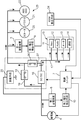
- FIG. 3 is a block diagram showing a specific configuration of the vehicle control device according to the present invention.
- the vehicle control device includes first voltage detection means 9 for detecting the voltage of the first power storage device 3;
- the second voltage detecting means 10 for detecting the voltage of the second power storage device 6 is provided, and the electric load capacity of the navigation device 11, the audio device 12, the meter unit 13, the vehicle interior lighting device 14, etc. is relatively small.
- a first power supply circuit 17 that connects the electrical load 15 and the second power storage device 6 via a DC / DC converter 16 is provided.
- the DC / DC converter 16 has a function of lowering the power supply voltage from the second power storage device 6 to a value corresponding to the operating voltage of the first electric load 15, for example, about 14V.
- the first power storage device 3 and the second power storage device 6 are connected by a second power feeding circuit 19 having a bypass relay 18 installed in parallel with the DC / DC converter 16 of the first power feeding circuit 17. Further, the second electric load 23 having a relatively large electric load capacity such as the starter 20 for starting the engine, the par steering device 21 and the ABS / DSC device 22 and the second power storage device 6 are connected to the second power feeding circuit. 19 is connected.
- the vehicle control device includes an ignition switch detection unit 24 that detects an operation state of the ignition switch of the vehicle, and a discharge unit 25 that includes a resistance circuit that discharges the electric power stored in the second power storage device 6. Is provided.
- the discharge means 25 detects that the ignition switch is turned off by the ignition switch detection means 24, and the second voltage detection means 10 sets a reference value in which the voltage of the second power storage device 6 is set in advance. (For example, about 16V) or more is discharged by grounding the electric power stored in the second power storage device 6 according to the control signal output from the control unit 7 through the vehicle body in response to the control signal output from the control unit 7 It is configured as follows.
- first power supply circuit 17 and the second power supply circuit 19 are connected to each other by a connection line 27 having a connection relay 26 in the downstream portion of the DC / DC converter 16 and the bypass relay 18.
- the bypass relay 18 of the second power feeding circuit 19 is turned off and the connection relay 26 is turned on normally, the current fed from the second power storage device 6 is In the state where the voltage is lowered to about 14 V via the DC / DC converter 16, the first electric load 15 including the navigation device 11 and the like is supplied through the first power feeding circuit 17, and the connection line 27 is connected to the first electric load 15.
- the first electric storage device 3 and the second electric load 23 are also supplied.
- the control unit 7 turns off the bypass relay 18 of the second power feeding circuit 19 and turns on the connection relay 26 of the connection line 27 as shown in FIG. Is executed.
- the generator 4 when the vehicle decelerates or travels downhill, the generator 4 generates power at a voltage of about 25 V, and the generated current is supplied to the second power storage device 6 and charged.
- the first power supply comprising the navigation device 11 and the like through the first power feeding circuit 17.
- it is effectively used by being supplied to the first power storage device 3 and the second electric load 23 through the connection line 27.
- the electric power of the second power storage device 6 is supplied to the first electric load 15 including the navigation device 11 and the like via the first power feeding circuit 17 having the DC / DC converter 16 and, if necessary, the above-mentioned
- the electric power is supplied to the first power storage device 3 and the second electric load 23 through the connection line 27.
- the voltage of the first power storage device 3 is lower than a standard voltage set to about 12 V, for example, the first power storage device 3 is charged by the feeding current from the second power storage device 6.
- the control signal output from the control unit 7 is shown in FIG. As shown, control for turning on the bypass relay 18 of the second power feeding circuit 19 and the connection relay 26 of the connection line 27 is executed.
- the generator 4 is driven by the engine of the vehicle to generate power at a voltage of about 12V to 14V, so that this generated current passes through the second power feeding circuit 19 and the first power storage device 3 and the first power generator 3.
- the first electric load 15 including the power steering device 21 and the like through the connection line 27, and charging the first power storage device 3 as necessary. Is done.
- the engine automatic stop control is performed to automatically stop the engine when the engine automatic stop condition is satisfied, and the starter 20 is operated when the restart condition of the engine in the automatic stop state is satisfied to operate the engine.
- the automatic stop control means (not shown) for automatically restarting the engine is provided in the control unit 7
- the second power storage device detected by the second voltage detection means 10 in the automatic stop state of the engine. 6 is determined to be an appropriate value set within the range of 14V to 25V
- the control unit 7 causes the bypass relay 18 and the connection line of the second power feeding circuit 19 to be connected as shown in FIG. Control for turning off the 27 connection relays 26 is executed.
- the power supply voltage of the second power storage device 6 is supplied to the first electric load 15 including the navigation device 11 and the like via the first power supply circuit 17 having the DC / DC converter 16.
- the second electric load 23 having a relatively large electric load capacity such as the starter 20 for starting the engine and the par steering device 21 as compared with the first electric load 15 including the audio device 12 or the like, Electric power from the first power storage device 3 is supplied.
- the second electrical storage device 6 has a relatively large electrical load capacity.
- a rated current or less for example, about 14 V or less. It is possible to effectively suppress the occurrence of a situation in which the first electrical load 15 made up of the audio device 12 or the like becomes unusable before the device is restarted.
- the ignition switch detection means 24 detects that the ignition switch has been turned off, and the second voltage detection means 10 detects that the voltage of the second power storage device 6 is equal to or higher than a preset reference value.
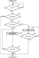
- a control operation for discharging the electric power stored in the second power storage device 6 by the discharging means 25 when it is detected will be described based on the flowchart shown in FIG.
- step S1 it is first determined whether or not the ignition switch has been turned off in accordance with the output signal of the ignition switch detection means 24 (step S1).
- step S2 the second voltage detection is performed. It is determined whether or not the voltage V2 of the second power storage device 6 detected by the means 10 is equal to or higher than a preset reference value (16V) (step S2). If the determination result in step S2 is NO and it is confirmed that the voltage V2 of the second power storage device 6 is less than the reference value (16V), the discharge control by the discharge means 25 and the like are not performed. Then, the process returns to end the control operation.
- step S2 When it is determined as YES in step S2 and it is confirmed that the voltage V2 of the second power storage device 6 is equal to or higher than the reference value (16V), the first power storage device detected by the first voltage detection means 9 It is determined whether or not the voltage V1 of 3 is less than the standard voltage set to about 12V in advance (step S3). If it is determined NO in step S3, control is performed to supply the electric power of the second power storage device 6 to the first power storage device 3 to store the power (step S4).
- step S5 it is determined whether or not the voltage V2 of the second power storage device 6 has decreased below a preset reference value (16V) (step S5). If NO is determined, the process returns to step S4. The control operation is repeated, and the control operation is ended when it is determined YES in Step S5.
- step S3 when it is determined as YES in step S3 and it is confirmed that the voltage V1 of the first power storage device 3 is equal to or higher than the standard voltage (about 12V), the discharge unit 25 is set in an operating state, and the second power storage As shown by the broken line in FIG. 3, control is performed to discharge the electric power of the device 6 to the ground (vehicle body) via the discharge means 25 (step S6).
- step S7 it is determined whether or not the voltage V2 of the second power storage device 6 detected by the second voltage detecting means 10 has dropped below the reference value (about 16V) (step S7). Returns to step S6 and continues the discharge control. And when it determines with YES by the said step S7 and it is confirmed that the voltage V2 of the 2nd electrical storage apparatus 6 fell below the said reference value (about 16V), the discharge control by the said discharge means 25 is complete
- the first power storage device 3 including a lead storage battery that can hold power for a long period of time, and the first power storage device A second power storage device 6 comprising a capacitor or the like that can be charged / discharged more rapidly than 3, an ignition switch detection means 24 for detecting the operation state of the ignition switch of the vehicle, and a voltage of the second power storage device 6.
- the second voltage detection means 10 and the ignition switch detection means 24 detect that the ignition switch has been turned off, and the second voltage detection means 10 presets the voltage of the second power storage device 6.
- the discharge means 25 is provided for discharging the power stored in the second power storage device 6 when it is detected that the value is equal to or higher than the reference value. It is possible to effectively utilize the electric energy of the vehicle, there is an advantage that the early deterioration of the second power storage device 6 can be effectively prevented.
- the second power storage device 6 composed of a capacitor capable of rapid charge / discharge is provided, and the vehicle is decelerated or traveling downhill.
- the generator 4 generates power at a voltage of about 25 V, supplies the generated current to the second power storage device 6 and charges it, and the power stored in the second power storage device 6 is converted into the DC / DC converter 16.
- the voltage of the second power storage device 6 detected by the second voltage detection means 10 is previously Since it is configured to execute the discharge control by the discharge means 25 when it is confirmed that it is equal to or higher than the set reference value (16V), the upper limit value of the charge voltage is set to a very high value compared to the lead storage battery or the like. It is possible to effectively set the early deterioration of the second power storage device 6 composed of a capacitor or the like that can be set and is liable to deteriorate early due to being left in a state where the storage voltage is maintained at a high value. There is an advantage that it can be prevented.
- the voltage of the second power storage device 6 detected by the second voltage detection means 10 becomes less than the preset reference value (16V).
- the discharge of the electric power stored in the second power storage device 6 is stopped at the time when the second power storage device 6 is detected, an early stage caused by the stored voltage of the second power storage device 6 becoming too low The occurrence of deterioration can be effectively prevented.
- the voltage of the second power storage device 6 drops below a rated value of about 9 V, power is generated by the generator 4.
- the discharge of power is stopped before the voltage of the second power storage device 6 becomes less than a preset reference value (16V)
- the occurrence of the above-described problems can be effectively prevented. There is an advantage that it can be prevented.
- the 1st voltage detection means 9 which detects the voltage of the 1st electrical storage apparatus 3 is provided, and when the ignition switch is switched from an ON state to an OFF state, the detection of the said 1st voltage detection means 9 is carried out. Since it is configured that the power of the second power storage device 6 is supplied to and stored in the first power storage device 3 when it is detected that the value is less than the standard voltage set in advance to about 12V, the second power This is because the electric power of the power storage device 6 can be prevented from being wasted and used effectively, and the voltage of the first power storage device 3 made of a lead storage battery or the like is excessively lowered after the engine is stopped. Thus, it is possible to effectively prevent the first power storage device 3 from being deteriorated early.
- the ignition switch has been switched from the on state to the off state in accordance with the detection signal of the ignition switch detection means 24, and the detection value of the first voltage detection means 9 is about 12V in advance.
- the control operation for supplying and storing the power of the second power storage device 6 is executed, and the power storage control for the first power storage device 3 is performed.
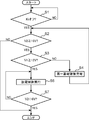
- the second power storage device 3 is configured to stop when it is confirmed that the voltage is less than the reference value, it may be configured as shown in FIG. 7 instead of this configuration.
- step S1 it is determined in step S1 that the ignition switch has been turned off, and in step S2, the voltage V2 of the second power storage device 6 is equal to or higher than a preset reference value (16V).
- step S3 the voltage V1 of the first power storage device 3 is not equal to or higher than the standard voltage set to about 12 V in advance
- step S4 the power storage control for the first power storage device 3 is started (step S3).
- step S4 returning to step S2, it is determined whether or not the voltage of the second power storage device 6 is equal to or higher than a reference voltage of about 16V, and in step S3, the voltage of the first power storage device 3 is equal to or higher than a standard voltage of about 12V. It is determined whether or not.
- Step S3 when it is determined YES in Step S3 and it is confirmed that the voltage of the second power storage device 6 is equal to or higher than the reference of about 16V and the voltage of the first power storage device 3 is equal to or higher than the standard voltage, You may comprise so that the electrical storage control with respect to the one electrical storage apparatus 3 may be stopped, it transfers to step S6, and the control which discharges the electric power of the 2nd electrical storage apparatus 6 by making the said discharge means 25 into an operation state.
- the electric power of the second power storage device 6 can be used effectively, and the early deterioration due to excessive reduction in the voltage of the first power storage device 3 made of a lead storage battery, There is an advantage that early deterioration of the second power storage device 6 made of a capacitor or the like can be effectively prevented.
- a hybrid capacitor such as a rechargeable ion capacitor or a high-power rechargeable ion battery may be used.
- the present invention described above is a vehicle control device that supplies electric power to an electric load of a vehicle, and includes a first power storage device capable of holding power for a long period of time, and charging more rapidly than the first power storage device.
- a second power storage device capable of discharging an ignition switch detecting means for detecting an operation state of the ignition switch of the vehicle, a voltage detecting means for detecting a voltage of the second power storage device, and an ignition switch by the ignition switch detecting means Is stored in the second power storage device when the voltage detecting means detects that the voltage of the second power storage device is equal to or higher than a preset reference value.
- Discharge means for discharging the generated electric power.
- a second power storage device made of a capacitor or the like capable of rapid charge / discharge is provided. While driving, the power generation current of the generator is supplied to the second power storage device and charged, so that the regenerative energy at the time of deceleration of the vehicle can be effectively used and the fuel efficiency of the vehicle can be effectively improved.
- the voltage of the second power storage device detected by the voltage detection means is equal to or higher than a preset reference value when it is confirmed that the ignition switch is turned off in response to the output signal of the ignition switch detection means. When it is confirmed that this is the case, it is possible to effectively prevent early deterioration of the second power storage device by executing the discharge control by the discharge means.
- the discharge unit is stored in the second power storage device when it is detected that the voltage of the second power storage device detected by the voltage detection unit is less than a preset reference value. It is also possible to configure so as to stop the discharge of the electric power.
- the second power storage device detected by the voltage detection unit when it is detected that the voltage of the second power storage device detected by the voltage detection unit is less than the preset reference value after the start of the discharge control by the discharge unit, the second power storage Since the discharge of the electric power stored in the device is stopped, there is an advantage that it is possible to effectively prevent the occurrence of early deterioration due to the stored voltage of the second power storage device becoming too low.
- the control device further includes first voltage detection means for detecting a voltage of the first power storage device, wherein the discharge means detects the first voltage detection when the ignition switch is switched from an on state to an off state.
- first voltage detection means for detecting a voltage of the first power storage device, wherein the discharge means detects the first voltage detection when the ignition switch is switched from an on state to an off state.
- the discharging means stops charging the first power storage device when it is detected that the detection value of the first voltage detecting means is equal to or higher than a preset upper limit reference value. It is also possible to start the discharge of the electric power stored in the second power storage device.
- the charging of the first power storage device is stopped when it is detected that the detection value of the first voltage detection means is equal to or higher than a preset upper limit reference value, and the discharging means Since it is configured to start discharging the power stored in the device, the power of the second power storage device can be used effectively, and the voltage of the first power storage device made of a lead storage battery or the like is excessively reduced. There is an advantage that the early deterioration and the early deterioration of the second power storage device made of a capacitor or the like can be effectively prevented.
- the electric load of the vehicle includes a first electric load having a relatively small electric load capacity and a second electric load having a relatively large electric load capacity.
- the first electric load includes a navigation device. , An audio device, a meter unit, and a vehicle interior lighting device, wherein the second electric load includes at least one of an engine starter, a par steering device, and an ABS / DSC device. To do.
- Automatic stop control means for automatically stopping the engine when a predetermined engine automatic stop condition is satisfied, In the automatic stop state of the engine, the power supply voltage of the first power storage device is supplied to the second electrical load, and the power supply voltage of the second power storage device is supplied to the first electrical load. It is also possible.
- the first electric load comprising the audio device or the like before the engine is restarted Generation
- the power supply voltage of the second power storage device is the first power storage device, It is also possible to be configured to be supplied to the first electric load and the second electric load.
- the power of the second power storage device is supplied to the first electric load consisting of the navigation device 11 and the like, and is supplied to the first power storage device 3 and the second electric load as necessary.
- the voltage of this 1st electrical storage apparatus is lower than the standard voltage set to about 12V, for example, the charge with respect to a 1st electrical storage apparatus is performed with the electric power feeding current from said 2nd electrical storage apparatus. Therefore, the electric power charged in the second power storage device can be effectively used.
Landscapes
- Engineering & Computer Science (AREA)
- Power Engineering (AREA)
- Transportation (AREA)
- Mechanical Engineering (AREA)
- Chemical & Material Sciences (AREA)
- Combustion & Propulsion (AREA)
- Charge And Discharge Circuits For Batteries Or The Like (AREA)
- Secondary Cells (AREA)
Abstract
Description
上記した本発明は、車両の電気負荷物に対して電力を供給する車両の制御装置であって、長期に亘り電力を保持可能な第一蓄電装置と、この第一蓄電装置よりも急速な充放電が可能な第二蓄電装置と、上記車両のイグニッションスイッチの操作状態を検出するイグニッションスイッチ検出手段と、上記第二蓄電装置の電圧を検出する電圧検出手段と、上記イグニッションスイッチ検出手段によりイグニッションスイッチのオフ操作が行われたことが検出されるとともに、上記電圧検出手段により第二蓄電装置の電圧が予め設定された基準値以上であることが検出された場合に、該第二蓄電装置に蓄えられた電力を放電させる放電手段とを備えたものである。
所定のエンジン自動停止条件が満たされたときにエンジンを自動的に停止させる自動停止制御手段をさらに備え、
前記エンジンの自動停止状態において、前記第一蓄電装置の給電電圧は前記第二電気負荷物に供給され、前記第二蓄電装置の給電電圧は前記第一電気負荷物に供給されるように構成することも可能である。
車両の通常運転状態において、前記電圧検出手段により検出された前記第二蓄電装置の電圧が予め定められた基準値以上である場合に、前記第二蓄電装置の給電電圧は前記第一蓄電装置、前記第一電気負荷物、及び、前記第二電気負荷物に供給されるように構成することも可能である。
Claims (8)
- 車両の電気負荷物に対して電力を供給する車両の制御装置であって、
長期に亘り電力を保持可能な第一蓄電装置と、
この第一蓄電装置よりも急速な充放電が可能な第二蓄電装置と、
上記車両のイグニッションスイッチの操作状態を検出するイグニッションスイッチ検出手段と、
上記第二蓄電装置の電圧を検出する電圧検出手段と、
上記イグニッションスイッチ検出手段によりイグニッションスイッチのオフ操作が行われたことが検出されるとともに、上記電圧検出手段により第二蓄電装置の電圧が予め設定された基準値以上であることが検出された場合に、該第二蓄電装置に蓄えられた電力を放電させる放電手段とを備えたことを特徴とする。 - 請求項1に記載の車両の制御装置において、上記放電手段は、電圧検出手段により検出された第二蓄電装置の電圧が予め設定された基準値未満となったことが検出された時点で、上記第二蓄電装置に蓄えられた電力の放電を停止するように構成されたことを特徴とする。
- 請求項1または2に記載の車両の制御装置において、上記第一蓄電装置の電圧を検出する第一電圧検出手段をさらに備え、上記放電手段は、イグニッションスイッチがオン状態からオフ状態に切り換えられた時点で、上記第一電圧検出手段の検出値が予め設定された規格電圧未満であることが検出された場合に第二蓄電装置の電力を第一蓄電装置に供給して蓄電するように構成されたことを特徴とする。
- 請求項3に記載の車両の制御装置において、上記放電手段は、第一電圧検出手段の検出値が予め設定された上限基準値以上となったことが検出された時点で、上記第一蓄電装置に対する充電を停止して第二蓄電装置に蓄えられた電力の放電を開始するように構成されたことを特徴とする。
- 請求項1~4の何れかに記載の車両の制御装置において、前記車両の電気負荷物は電気負荷容量が比較的小さい第一電気負荷物と電気負荷容量が比較的大きい第二電気負荷物とを備えていることを特徴とする。
- 請求項5に記載の車両の制御装置において、前記第一電気負荷物は、ナビゲーション装置、オーディオ装置、メータユニットおよび車室内照明装置の少なくともひとつを備え、
前記第二電気負荷物は、エンジン始動用のスタータ、パーステアリング装置およびABS・DSC装置の少なくともひとつを備えていることを特徴とする。 - 請求項6に記載の車両の制御装置において、
所定のエンジン自動停止条件が満たされたときにエンジンを自動的に停止させる自動停止制御手段をさらに備え、
前記エンジンの自動停止状態において、前記第一蓄電装置の給電電圧は前記第二電気負荷物に供給され、前記第二蓄電装置の給電電圧は前記第一電気負荷物に供給されることを特徴とする。 - 請求項6に記載の車両の制御装置において、
車両の通常運転状態において、前記電圧検出手段により検出された前記第二蓄電装置の電圧が予め定められた基準値以上である場合に、前記第二蓄電装置の給電電圧は前記第一蓄電装置、前記第一電気負荷物、及び、前記第二電気負荷物に供給されることを特徴とする。
Priority Applications (3)
| Application Number | Priority Date | Filing Date | Title |
|---|---|---|---|
| DE112012002123.1T DE112012002123B4 (de) | 2011-05-17 | 2012-05-11 | Fahrzeugsteuervorrichtung |
| CN201280023681.2A CN103534143B (zh) | 2011-05-17 | 2012-05-11 | 车辆的控制装置 |
| US14/118,156 US9254751B2 (en) | 2011-05-17 | 2012-05-11 | Vehicle control device |
Applications Claiming Priority (2)
| Application Number | Priority Date | Filing Date | Title |
|---|---|---|---|
| JP2011110435A JP5609768B2 (ja) | 2011-05-17 | 2011-05-17 | 車両の制御装置 |
| JP2011-110435 | 2011-05-17 |
Publications (1)
| Publication Number | Publication Date |
|---|---|
| WO2012157235A1 true WO2012157235A1 (ja) | 2012-11-22 |
Family
ID=47176587
Family Applications (1)
| Application Number | Title | Priority Date | Filing Date |
|---|---|---|---|
| PCT/JP2012/003092 Ceased WO2012157235A1 (ja) | 2011-05-17 | 2012-05-11 | 車両の制御装置 |
Country Status (5)
| Country | Link |
|---|---|
| US (1) | US9254751B2 (ja) |
| JP (1) | JP5609768B2 (ja) |
| CN (1) | CN103534143B (ja) |
| DE (1) | DE112012002123B4 (ja) |
| WO (1) | WO2012157235A1 (ja) |
Cited By (1)
| Publication number | Priority date | Publication date | Assignee | Title |
|---|---|---|---|---|
| CN104442439A (zh) * | 2014-11-27 | 2015-03-25 | 苏州吉联智能科技有限公司 | 电能分配管理的汽车电源管理系统 |
Families Citing this family (34)
| Publication number | Priority date | Publication date | Assignee | Title |
|---|---|---|---|---|
| JP5609768B2 (ja) * | 2011-05-17 | 2014-10-22 | マツダ株式会社 | 車両の制御装置 |
| JP5998755B2 (ja) * | 2012-08-30 | 2016-09-28 | マツダ株式会社 | 車両用電源制御装置および方法 |
| JP6297496B2 (ja) * | 2012-10-29 | 2018-03-20 | 三洋電機株式会社 | 車載用電池システム |
| JP6020284B2 (ja) * | 2013-03-26 | 2016-11-02 | 株式会社オートネットワーク技術研究所 | 電源装置 |
| JP6036571B2 (ja) * | 2013-06-19 | 2016-11-30 | 株式会社オートネットワーク技術研究所 | 出力装置及び負荷給電システム |
| JP5941019B2 (ja) * | 2013-07-02 | 2016-06-29 | 本田技研工業株式会社 | 車両用電源装置 |
| CN106575875B (zh) * | 2014-09-29 | 2021-07-23 | 柏思科技有限公司 | 用于管理在装置处的电源的方法和系统 |
| US10320202B2 (en) * | 2014-09-30 | 2019-06-11 | Johnson Controls Technology Company | Battery system bi-stable relay control |
| US9452672B2 (en) * | 2014-12-30 | 2016-09-27 | GM Global Technology Operations LLC | Vehicle powertrain |
| FR3033955B1 (fr) * | 2015-03-17 | 2017-03-17 | Valeo Systemes Thermiques | Dispositif de pilotage d'alimentation electrique de circuit pour un vehicule comprenant une batterie et ensemble correspondant |
| JP6240118B2 (ja) * | 2015-05-25 | 2017-11-29 | トヨタ自動車株式会社 | 電動車両 |
| CN104908685A (zh) * | 2015-05-28 | 2015-09-16 | 桂林电子科技大学 | 一种汽车电子系统自动节电控制装置 |
| JP6551089B2 (ja) * | 2015-09-11 | 2019-07-31 | 株式会社オートネットワーク技術研究所 | 車載用電源装置 |
| JP6387940B2 (ja) * | 2015-10-22 | 2018-09-12 | 株式会社オートネットワーク技術研究所 | 車載用電源装置 |
| JP6540565B2 (ja) * | 2016-03-16 | 2019-07-10 | 株式会社オートネットワーク技術研究所 | 車両用電源供給システム、車両用駆動システム |
| JP6662178B2 (ja) * | 2016-04-25 | 2020-03-11 | 株式会社オートネットワーク技術研究所 | 車載電源用のスイッチ装置 |
| US10086709B2 (en) * | 2016-06-14 | 2018-10-02 | Ford Global Technologies, Llc | Variable wakeup of a high-voltage charger based on low-voltage system parameters |
| CN106080452A (zh) * | 2016-07-29 | 2016-11-09 | 北京车和家信息技术有限责任公司 | 电子控制单元的供电方法、电子控制单元和车辆 |
| JP6627693B2 (ja) | 2016-08-31 | 2020-01-08 | 株式会社オートネットワーク技術研究所 | 蓄電部制御装置 |
| WO2018043538A1 (ja) * | 2016-08-31 | 2018-03-08 | パナソニックIpマネジメント株式会社 | 車両用蓄電装置 |
| JP6719353B2 (ja) * | 2016-09-26 | 2020-07-08 | 株式会社デンソーテン | 給電制御装置および給電制御システム |
| KR101907373B1 (ko) * | 2016-11-16 | 2018-10-12 | 현대오트론 주식회사 | 과충전 방지 장치 및 방법 |
| US10479220B2 (en) * | 2017-04-11 | 2019-11-19 | GM Global Technology Operations LLC | Hybrid powertrain with dual energy storage devices |
| CN111130091B (zh) * | 2018-10-30 | 2021-08-27 | 中国科学院大连化学物理研究所 | 一种用于水下供电的组合能源系统 |
| JP7146675B2 (ja) * | 2019-03-14 | 2022-10-04 | ヤンマーパワーテクノロジー株式会社 | 自動走行システム |
| JP7074725B2 (ja) * | 2019-07-18 | 2022-05-24 | 矢崎総業株式会社 | 電源システム、dcdcコンバータ装置、及び充電方法 |
| CN114391205A (zh) * | 2019-09-27 | 2022-04-22 | 株式会社自动网络技术研究所 | 电源系统 |
| JP7310575B2 (ja) * | 2019-12-06 | 2023-07-19 | トヨタ自動車株式会社 | 車両用制御装置 |
| KR102824805B1 (ko) * | 2019-12-16 | 2025-06-25 | 현대자동차주식회사 | 차량 및 차량의 제어방법 |
| CN111478385A (zh) * | 2020-03-23 | 2020-07-31 | 义乌吉利动力总成有限公司 | 一种车辆低压保护控制方法、装置、系统及计算机存储介质 |
| US12576738B2 (en) * | 2022-06-14 | 2026-03-17 | Universal City Studios Llc | Docked interlock system and method |
| JP2023183645A (ja) * | 2022-06-16 | 2023-12-28 | トヨタ自動車株式会社 | 電源装置及び車両 |
| CN115107676B (zh) * | 2022-06-28 | 2025-08-29 | 安徽江淮汽车集团股份有限公司 | 一种整车启动过程中的低压故障诊断方法及装置 |
| WO2024245625A1 (en) * | 2023-05-30 | 2024-12-05 | Mercedes-Benz Group AG | Charging system for rechargeable batteries with metal deposition based electrodes |
Citations (4)
| Publication number | Priority date | Publication date | Assignee | Title |
|---|---|---|---|---|
| JP2004229447A (ja) * | 2003-01-24 | 2004-08-12 | Toyota Motor Corp | 車両用電源装置 |
| JP2006304393A (ja) * | 2005-04-15 | 2006-11-02 | Toyota Motor Corp | 電源装置およびその制御方法並びに車両 |
| JP2007161000A (ja) * | 2005-12-12 | 2007-06-28 | Toyota Motor Corp | 車両用電源制御装置 |
| JP2009166769A (ja) * | 2008-01-18 | 2009-07-30 | Denso Corp | 車載装置の電源システム |
Family Cites Families (6)
| Publication number | Priority date | Publication date | Assignee | Title |
|---|---|---|---|---|
| JP3624831B2 (ja) * | 2000-12-28 | 2005-03-02 | 株式会社デンソー | 車両用電源装置及びエンジン駆動規制支援装置 |
| US6753673B2 (en) * | 2002-05-14 | 2004-06-22 | Luxon Energy Devices Corporation | Power module for providing impulses of various levels by charging or discharging capacitors therewith |
| DE102005055004A1 (de) * | 2005-11-18 | 2007-05-24 | Bayerische Motoren Werke Ag | Verfahren zum Steuern des Bordnetzes eines Kraftfahrzeugs |
| JP5247001B2 (ja) | 2006-01-11 | 2013-07-24 | 富士通テン株式会社 | 車両の電源制御装置 |
| JP4144646B1 (ja) * | 2007-02-20 | 2008-09-03 | トヨタ自動車株式会社 | 電動車両、車両充電装置および車両充電システム |
| JP5609768B2 (ja) * | 2011-05-17 | 2014-10-22 | マツダ株式会社 | 車両の制御装置 |
-
2011
- 2011-05-17 JP JP2011110435A patent/JP5609768B2/ja not_active Expired - Fee Related
-
2012
- 2012-05-11 CN CN201280023681.2A patent/CN103534143B/zh not_active Expired - Fee Related
- 2012-05-11 DE DE112012002123.1T patent/DE112012002123B4/de not_active Expired - Fee Related
- 2012-05-11 WO PCT/JP2012/003092 patent/WO2012157235A1/ja not_active Ceased
- 2012-05-11 US US14/118,156 patent/US9254751B2/en not_active Expired - Fee Related
Patent Citations (4)
| Publication number | Priority date | Publication date | Assignee | Title |
|---|---|---|---|---|
| JP2004229447A (ja) * | 2003-01-24 | 2004-08-12 | Toyota Motor Corp | 車両用電源装置 |
| JP2006304393A (ja) * | 2005-04-15 | 2006-11-02 | Toyota Motor Corp | 電源装置およびその制御方法並びに車両 |
| JP2007161000A (ja) * | 2005-12-12 | 2007-06-28 | Toyota Motor Corp | 車両用電源制御装置 |
| JP2009166769A (ja) * | 2008-01-18 | 2009-07-30 | Denso Corp | 車載装置の電源システム |
Cited By (1)
| Publication number | Priority date | Publication date | Assignee | Title |
|---|---|---|---|---|
| CN104442439A (zh) * | 2014-11-27 | 2015-03-25 | 苏州吉联智能科技有限公司 | 电能分配管理的汽车电源管理系统 |
Also Published As
| Publication number | Publication date |
|---|---|
| JP2012240486A (ja) | 2012-12-10 |
| DE112012002123B4 (de) | 2019-01-31 |
| US9254751B2 (en) | 2016-02-09 |
| JP5609768B2 (ja) | 2014-10-22 |
| CN103534143A (zh) | 2014-01-22 |
| US20140077771A1 (en) | 2014-03-20 |
| CN103534143B (zh) | 2016-02-17 |
| DE112012002123T5 (de) | 2014-02-13 |
Similar Documents
| Publication | Publication Date | Title |
|---|---|---|
| JP5609768B2 (ja) | 車両の制御装置 | |
| CN102785585B (zh) | 车辆的电力供应控制装置 | |
| JP5696585B2 (ja) | 車両の電源制御装置 | |
| US9780577B2 (en) | Electric power supply control device and electric power supply control method | |
| JP6111536B2 (ja) | 車両用電源制御方法及び装置 | |
| JP5029331B2 (ja) | 車両用電源装置 | |
| JP6371791B2 (ja) | 車両用電源装置 | |
| US20180233943A1 (en) | Power supply system for vehicle | |
| JP6467451B2 (ja) | 車両用電源装置 | |
| CN103660961B (zh) | 车辆用电源的控制装置及控制方法 | |
| JP6107679B2 (ja) | 車両の制御装置 | |
| JP2015048064A (ja) | 車両 | |
| JP2014184752A (ja) | 電源装置 | |
| JP2016201871A (ja) | 蓄電システム | |
| WO2014068920A1 (ja) | アイドリングストップする車両 | |
| JP6669274B2 (ja) | 車両用電源システムの制御方法および車両用電源システム | |
| JP2015009654A (ja) | 蓄電システム | |
| JP6136792B2 (ja) | 車両用電源装置 | |
| JP6131533B2 (ja) | 車両用電源制御方法及び装置 | |
| JP5915390B2 (ja) | 車両用電源制御方法及び装置 | |
| CN102164798A (zh) | 用于调节或控制混合动力车的电蓄能器的荷电状态的方法 | |
| JP7021570B2 (ja) | 車両の電力制御装置 | |
| KR20180008976A (ko) | 자동차용 배터리 과충전 방지 시스템 및 그 제어방법 | |
| JP2007181328A (ja) | 車両用制御装置 | |
| JP2017154604A (ja) | 電源装置及び電源装置の制御方法 |
Legal Events
| Date | Code | Title | Description |
|---|---|---|---|
| WWE | Wipo information: entry into national phase |
Ref document number: 201280023681.2 Country of ref document: CN |
|
| 121 | Ep: the epo has been informed by wipo that ep was designated in this application |
Ref document number: 12785048 Country of ref document: EP Kind code of ref document: A1 |
|
| DPE1 | Request for preliminary examination filed after expiration of 19th month from priority date (pct application filed from 20040101) | ||
| WWE | Wipo information: entry into national phase |
Ref document number: 14118156 Country of ref document: US |
|
| WWE | Wipo information: entry into national phase |
Ref document number: 1120120021231 Country of ref document: DE Ref document number: 112012002123 Country of ref document: DE |
|
| 122 | Ep: pct application non-entry in european phase |
Ref document number: 12785048 Country of ref document: EP Kind code of ref document: A1 |