WO2012156647A1 - Piece avec revetement dlc et procede d'application du revetement dlc - Google Patents
Piece avec revetement dlc et procede d'application du revetement dlc Download PDFInfo
- Publication number
- WO2012156647A1 WO2012156647A1 PCT/FR2012/051109 FR2012051109W WO2012156647A1 WO 2012156647 A1 WO2012156647 A1 WO 2012156647A1 FR 2012051109 W FR2012051109 W FR 2012051109W WO 2012156647 A1 WO2012156647 A1 WO 2012156647A1
- Authority
- WO
- WIPO (PCT)
- Prior art keywords
- layer
- dlc
- coating
- thickness
- μηι
- Prior art date
Links
Classifications
-
- C—CHEMISTRY; METALLURGY
- C23—COATING METALLIC MATERIAL; COATING MATERIAL WITH METALLIC MATERIAL; CHEMICAL SURFACE TREATMENT; DIFFUSION TREATMENT OF METALLIC MATERIAL; COATING BY VACUUM EVAPORATION, BY SPUTTERING, BY ION IMPLANTATION OR BY CHEMICAL VAPOUR DEPOSITION, IN GENERAL; INHIBITING CORROSION OF METALLIC MATERIAL OR INCRUSTATION IN GENERAL
- C23C—COATING METALLIC MATERIAL; COATING MATERIAL WITH METALLIC MATERIAL; SURFACE TREATMENT OF METALLIC MATERIAL BY DIFFUSION INTO THE SURFACE, BY CHEMICAL CONVERSION OR SUBSTITUTION; COATING BY VACUUM EVAPORATION, BY SPUTTERING, BY ION IMPLANTATION OR BY CHEMICAL VAPOUR DEPOSITION, IN GENERAL
- C23C14/00—Coating by vacuum evaporation, by sputtering or by ion implantation of the coating forming material
- C23C14/06—Coating by vacuum evaporation, by sputtering or by ion implantation of the coating forming material characterised by the coating material
- C23C14/0605—Carbon
- C23C14/0611—Diamond
-
- C—CHEMISTRY; METALLURGY
- C23—COATING METALLIC MATERIAL; COATING MATERIAL WITH METALLIC MATERIAL; CHEMICAL SURFACE TREATMENT; DIFFUSION TREATMENT OF METALLIC MATERIAL; COATING BY VACUUM EVAPORATION, BY SPUTTERING, BY ION IMPLANTATION OR BY CHEMICAL VAPOUR DEPOSITION, IN GENERAL; INHIBITING CORROSION OF METALLIC MATERIAL OR INCRUSTATION IN GENERAL
- C23C—COATING METALLIC MATERIAL; COATING MATERIAL WITH METALLIC MATERIAL; SURFACE TREATMENT OF METALLIC MATERIAL BY DIFFUSION INTO THE SURFACE, BY CHEMICAL CONVERSION OR SUBSTITUTION; COATING BY VACUUM EVAPORATION, BY SPUTTERING, BY ION IMPLANTATION OR BY CHEMICAL VAPOUR DEPOSITION, IN GENERAL
- C23C28/00—Coating for obtaining at least two superposed coatings either by methods not provided for in a single one of groups C23C2/00 - C23C26/00 or by combinations of methods provided for in subclasses C23C and C25C or C25D
- C23C28/04—Coating for obtaining at least two superposed coatings either by methods not provided for in a single one of groups C23C2/00 - C23C26/00 or by combinations of methods provided for in subclasses C23C and C25C or C25D only coatings of inorganic non-metallic material
-
- C—CHEMISTRY; METALLURGY
- C23—COATING METALLIC MATERIAL; COATING MATERIAL WITH METALLIC MATERIAL; CHEMICAL SURFACE TREATMENT; DIFFUSION TREATMENT OF METALLIC MATERIAL; COATING BY VACUUM EVAPORATION, BY SPUTTERING, BY ION IMPLANTATION OR BY CHEMICAL VAPOUR DEPOSITION, IN GENERAL; INHIBITING CORROSION OF METALLIC MATERIAL OR INCRUSTATION IN GENERAL
- C23C—COATING METALLIC MATERIAL; COATING MATERIAL WITH METALLIC MATERIAL; SURFACE TREATMENT OF METALLIC MATERIAL BY DIFFUSION INTO THE SURFACE, BY CHEMICAL CONVERSION OR SUBSTITUTION; COATING BY VACUUM EVAPORATION, BY SPUTTERING, BY ION IMPLANTATION OR BY CHEMICAL VAPOUR DEPOSITION, IN GENERAL
- C23C14/00—Coating by vacuum evaporation, by sputtering or by ion implantation of the coating forming material
- C23C14/02—Pretreatment of the material to be coated
- C23C14/021—Cleaning or etching treatments
- C23C14/022—Cleaning or etching treatments by means of bombardment with energetic particles or radiation
-
- C—CHEMISTRY; METALLURGY
- C23—COATING METALLIC MATERIAL; COATING MATERIAL WITH METALLIC MATERIAL; CHEMICAL SURFACE TREATMENT; DIFFUSION TREATMENT OF METALLIC MATERIAL; COATING BY VACUUM EVAPORATION, BY SPUTTERING, BY ION IMPLANTATION OR BY CHEMICAL VAPOUR DEPOSITION, IN GENERAL; INHIBITING CORROSION OF METALLIC MATERIAL OR INCRUSTATION IN GENERAL
- C23C—COATING METALLIC MATERIAL; COATING MATERIAL WITH METALLIC MATERIAL; SURFACE TREATMENT OF METALLIC MATERIAL BY DIFFUSION INTO THE SURFACE, BY CHEMICAL CONVERSION OR SUBSTITUTION; COATING BY VACUUM EVAPORATION, BY SPUTTERING, BY ION IMPLANTATION OR BY CHEMICAL VAPOUR DEPOSITION, IN GENERAL
- C23C14/00—Coating by vacuum evaporation, by sputtering or by ion implantation of the coating forming material
- C23C14/02—Pretreatment of the material to be coated
- C23C14/024—Deposition of sublayers, e.g. to promote adhesion of the coating
-
- C—CHEMISTRY; METALLURGY
- C23—COATING METALLIC MATERIAL; COATING MATERIAL WITH METALLIC MATERIAL; CHEMICAL SURFACE TREATMENT; DIFFUSION TREATMENT OF METALLIC MATERIAL; COATING BY VACUUM EVAPORATION, BY SPUTTERING, BY ION IMPLANTATION OR BY CHEMICAL VAPOUR DEPOSITION, IN GENERAL; INHIBITING CORROSION OF METALLIC MATERIAL OR INCRUSTATION IN GENERAL
- C23C—COATING METALLIC MATERIAL; COATING MATERIAL WITH METALLIC MATERIAL; SURFACE TREATMENT OF METALLIC MATERIAL BY DIFFUSION INTO THE SURFACE, BY CHEMICAL CONVERSION OR SUBSTITUTION; COATING BY VACUUM EVAPORATION, BY SPUTTERING, BY ION IMPLANTATION OR BY CHEMICAL VAPOUR DEPOSITION, IN GENERAL
- C23C14/00—Coating by vacuum evaporation, by sputtering or by ion implantation of the coating forming material
- C23C14/06—Coating by vacuum evaporation, by sputtering or by ion implantation of the coating forming material characterised by the coating material
- C23C14/0605—Carbon
-
- C—CHEMISTRY; METALLURGY
- C23—COATING METALLIC MATERIAL; COATING MATERIAL WITH METALLIC MATERIAL; CHEMICAL SURFACE TREATMENT; DIFFUSION TREATMENT OF METALLIC MATERIAL; COATING BY VACUUM EVAPORATION, BY SPUTTERING, BY ION IMPLANTATION OR BY CHEMICAL VAPOUR DEPOSITION, IN GENERAL; INHIBITING CORROSION OF METALLIC MATERIAL OR INCRUSTATION IN GENERAL
- C23C—COATING METALLIC MATERIAL; COATING MATERIAL WITH METALLIC MATERIAL; SURFACE TREATMENT OF METALLIC MATERIAL BY DIFFUSION INTO THE SURFACE, BY CHEMICAL CONVERSION OR SUBSTITUTION; COATING BY VACUUM EVAPORATION, BY SPUTTERING, BY ION IMPLANTATION OR BY CHEMICAL VAPOUR DEPOSITION, IN GENERAL
- C23C28/00—Coating for obtaining at least two superposed coatings either by methods not provided for in a single one of groups C23C2/00 - C23C26/00 or by combinations of methods provided for in subclasses C23C and C25C or C25D
- C23C28/04—Coating for obtaining at least two superposed coatings either by methods not provided for in a single one of groups C23C2/00 - C23C26/00 or by combinations of methods provided for in subclasses C23C and C25C or C25D only coatings of inorganic non-metallic material
- C23C28/044—Coating for obtaining at least two superposed coatings either by methods not provided for in a single one of groups C23C2/00 - C23C26/00 or by combinations of methods provided for in subclasses C23C and C25C or C25D only coatings of inorganic non-metallic material coatings specially adapted for cutting tools or wear applications
-
- C—CHEMISTRY; METALLURGY
- C23—COATING METALLIC MATERIAL; COATING MATERIAL WITH METALLIC MATERIAL; CHEMICAL SURFACE TREATMENT; DIFFUSION TREATMENT OF METALLIC MATERIAL; COATING BY VACUUM EVAPORATION, BY SPUTTERING, BY ION IMPLANTATION OR BY CHEMICAL VAPOUR DEPOSITION, IN GENERAL; INHIBITING CORROSION OF METALLIC MATERIAL OR INCRUSTATION IN GENERAL
- C23C—COATING METALLIC MATERIAL; COATING MATERIAL WITH METALLIC MATERIAL; SURFACE TREATMENT OF METALLIC MATERIAL BY DIFFUSION INTO THE SURFACE, BY CHEMICAL CONVERSION OR SUBSTITUTION; COATING BY VACUUM EVAPORATION, BY SPUTTERING, BY ION IMPLANTATION OR BY CHEMICAL VAPOUR DEPOSITION, IN GENERAL
- C23C28/00—Coating for obtaining at least two superposed coatings either by methods not provided for in a single one of groups C23C2/00 - C23C26/00 or by combinations of methods provided for in subclasses C23C and C25C or C25D
- C23C28/04—Coating for obtaining at least two superposed coatings either by methods not provided for in a single one of groups C23C2/00 - C23C26/00 or by combinations of methods provided for in subclasses C23C and C25C or C25D only coatings of inorganic non-metallic material
- C23C28/046—Coating for obtaining at least two superposed coatings either by methods not provided for in a single one of groups C23C2/00 - C23C26/00 or by combinations of methods provided for in subclasses C23C and C25C or C25D only coatings of inorganic non-metallic material with at least one amorphous inorganic material layer, e.g. DLC, a-C:H, a-C:Me, the layer being doped or not
-
- C—CHEMISTRY; METALLURGY
- C23—COATING METALLIC MATERIAL; COATING MATERIAL WITH METALLIC MATERIAL; CHEMICAL SURFACE TREATMENT; DIFFUSION TREATMENT OF METALLIC MATERIAL; COATING BY VACUUM EVAPORATION, BY SPUTTERING, BY ION IMPLANTATION OR BY CHEMICAL VAPOUR DEPOSITION, IN GENERAL; INHIBITING CORROSION OF METALLIC MATERIAL OR INCRUSTATION IN GENERAL
- C23C—COATING METALLIC MATERIAL; COATING MATERIAL WITH METALLIC MATERIAL; SURFACE TREATMENT OF METALLIC MATERIAL BY DIFFUSION INTO THE SURFACE, BY CHEMICAL CONVERSION OR SUBSTITUTION; COATING BY VACUUM EVAPORATION, BY SPUTTERING, BY ION IMPLANTATION OR BY CHEMICAL VAPOUR DEPOSITION, IN GENERAL
- C23C28/00—Coating for obtaining at least two superposed coatings either by methods not provided for in a single one of groups C23C2/00 - C23C26/00 or by combinations of methods provided for in subclasses C23C and C25C or C25D
- C23C28/04—Coating for obtaining at least two superposed coatings either by methods not provided for in a single one of groups C23C2/00 - C23C26/00 or by combinations of methods provided for in subclasses C23C and C25C or C25D only coatings of inorganic non-metallic material
- C23C28/048—Coating for obtaining at least two superposed coatings either by methods not provided for in a single one of groups C23C2/00 - C23C26/00 or by combinations of methods provided for in subclasses C23C and C25C or C25D only coatings of inorganic non-metallic material with layers graded in composition or physical properties
-
- Y—GENERAL TAGGING OF NEW TECHNOLOGICAL DEVELOPMENTS; GENERAL TAGGING OF CROSS-SECTIONAL TECHNOLOGIES SPANNING OVER SEVERAL SECTIONS OF THE IPC; TECHNICAL SUBJECTS COVERED BY FORMER USPC CROSS-REFERENCE ART COLLECTIONS [XRACs] AND DIGESTS
- Y10—TECHNICAL SUBJECTS COVERED BY FORMER USPC
- Y10T—TECHNICAL SUBJECTS COVERED BY FORMER US CLASSIFICATION
- Y10T428/00—Stock material or miscellaneous articles
- Y10T428/30—Self-sustaining carbon mass or layer with impregnant or other layer
Definitions
- the invention relates to the technical sector of DLC coatings especially for friction parts.
- the invention finds a particularly advantageous application for reducing the coefficient of friction, for example piston pins, cam shafts, pushers, cylinders, segments, and more generally, in all cases of friction loaded.
- it is well known to a person skilled in the art to subject the part or parts concerned to a DLC coating.
- the invention can also find applications in which it seeks a black color of the surface provided by the coating without seeking a reduction of friction.
- WO201 1/018252 discloses with a friction piece a coating consisting of an underlayer hooked, a metal coating DLC and a DLC coating without metal.
- the hook layer is preferably a chromium coating with a maximum thickness of ⁇ while the metal coating DLC is preferably tungsten carbide WCC.
- the thickness ratios of the different layers and coatings are limited to ranges of values so that outside of these ranges, if the thickness of DLC is too low, the The service life of the part will also be reduced while if the thickness of DLC is too great, the part will have premature wear with risk of flaking.
- WO0179585 discloses a multilayer system having a hook layer, a transition layer and an adamantine carbon layer.
- the hook layer comprises a group 4, 5 or 6 element and silicon, while the transition layer comprises carbon or at least one group 4, 5, or 6 element and silicon.
- the upper layer is mainly adiamantin carbon.
- the system has a hardness of at least 15 GPa and an adhesion of at least HF3.
- the problem to be solved by the invention is to produce DLC films having improved adhesion without using an undercoat of metallic hook, silicon or chromium for example, as is apparent from the teaching of the state of the art.
- microwave stripping of the part is carried out
- the part is subjected to a gradient layer of composition WC-C; the DLC coating is applied to the WC-C layer by microwave plasma;
- Microwave stripping makes it possible, compared with stripping using diode technology, to obtain a stripping that is more efficient and independent of the geometry of the part to be treated by adjusting the flow of ions. It is also possible to perform stripping on low temperature parts of income, without altering them. It is also observed that the use of a microwave DLC coating makes it possible to reduce the application process time by about 50% compared to a conventional DLC.
- an argon plasma is generated for etching in a pressure range of between 0.05 and 0.5 Pa.
- the WC-C composition gradient layer is produced by magnetron PVD technique. We start from a first layer of pure WC followed by a ramp with a hydrocarbon gas such as C 2 H 2 and finally followed by a WC-C layer.
- the thickness of the gradient layer WC-C composition is between 0.3 and ⁇ and advantageously 0.8 ⁇ for most applications, except those requiring greater thicknesses as for segments
- the DLC coating has a thickness of between 1 and 20 ⁇ m.
- the invention also relates to a friction piece coated with DLC applied to a layer of WC-C composition gradient present in the part stripped by microwave technology.
- FIG. 1 is a view of the rupture profile of the coating according to the scratch test method.
- FIG. 2 is a sectional view along the line A-A of Figure 1 in the case of adhesive peeling.
- FIG. 3 is a sectional view along the line A-A of FIG. 1, in the case of cohesive peeling.
- FIG. 4 is a sectional view along the line
- DLC coatings including, in all cases, an adhesion sub-layer made, for example, of pure Cr, followed by a tungsten carbide-based layer in which the The carbon is progressively increased until a DLC layer is obtained, doped with tungsten, with the aim of ensuring the adhesion of an undoped DLC deposit with metal.
- tests have been carried out in order to compare the results obtained in the case of realizations of DLC coatings with one or more adhesion and coating sublayers that do not use a coating layer.
- Different ion pickling technologies are known to those skilled in the art, namely essentially diode technology, triode amplified plasma technology, and microwave triode technology EC system.
- the diode technology consists in applying a negative voltage to the substrates of a few hundred volts ( ⁇ -500V), in an argon atmosphere of 1 to 10 Pa. Under these conditions, a glow discharge appears around the pieces, from which the positive argon ions of the plasma bombard the surface of the substrate allowing the surface to be sprayed and the oxide to be removed.
- a dense argon plasma at lower pressure (0.1 to 1 Pa) is generated by a plasma amplification device.
- the positive argon ions of the plasma are accelerated by negative polarization of the substrate and etch the surface.
- the negative voltage must be between -250V and -500V to show its maximum efficiency in terms of stripping.
- the triode technology microwave ECR system can generate an argon plasma in a pressure range between 0.05 and 0.5 Pa.
- the parts are biased to a negative voltage optimally between -50V and - 250V .
- each stripping technology was used. Following the stripping, on a part of the specimens, an undercoat pure chromium adhesion was carried out by magnetron sputtering, to obtain a chromium thickness of the order of 0.1 to 0.2 ⁇ .
- a deposition of tungsten carbide was then carried out by magnetron sputtering, progressively introducing an increasing flow of hydrocarbon, allowing the enrichment of the carbon deposit at a content greater than 50 at. allow adhesion of the final layer of DLC.
- the layer containing tungsten has a thickness of the order of 0.5 ⁇ and that of the DLC of the order of 2 ⁇ with the exception of Examples 9 and 10, for which the thickness of the layer containing tungsten is increased. at 1.5 ⁇ .
- the scratch test method was used. It is recalled that this method consists in scratching the surface of the deposit with a diamond such as those used in indentation H C. A gradually increasing load is applied while the specimen is translated at a constant speed under the diamond. This makes it possible to obtain a stripe with increasing load (FIG. 1) from which it is possible to determine a flaking force (critical load), as well as the flaking mode. The flaking mode indicates the location of the coating failure. There are 2 large families of flaking:
- Adhesive spalling is the propagation of cracks along an interface, thus parallel to the surface of the part, while cohesive spalling propagates through the coating at an oblique angle to the interfaces.
- Adhesive peeling characterizes a lack of adhesion of the coating. Cohesive peeling occurs when the stresses exceed the breaking limit of the materials constituting the coating.
- the critical load characterizes the adhesive force.
- the adhesion In the case of a cohesive failure, the adhesion is not characterized, but the breaking strength of the coating.
- the critical load is not only a characteristic of the deposit, but also a characteristic of its thickness and the hardness of the substrate.
- a second method for evaluating adhesion was used. It involves indenting the deposit with a Vickers diamond under a load of 2kg.
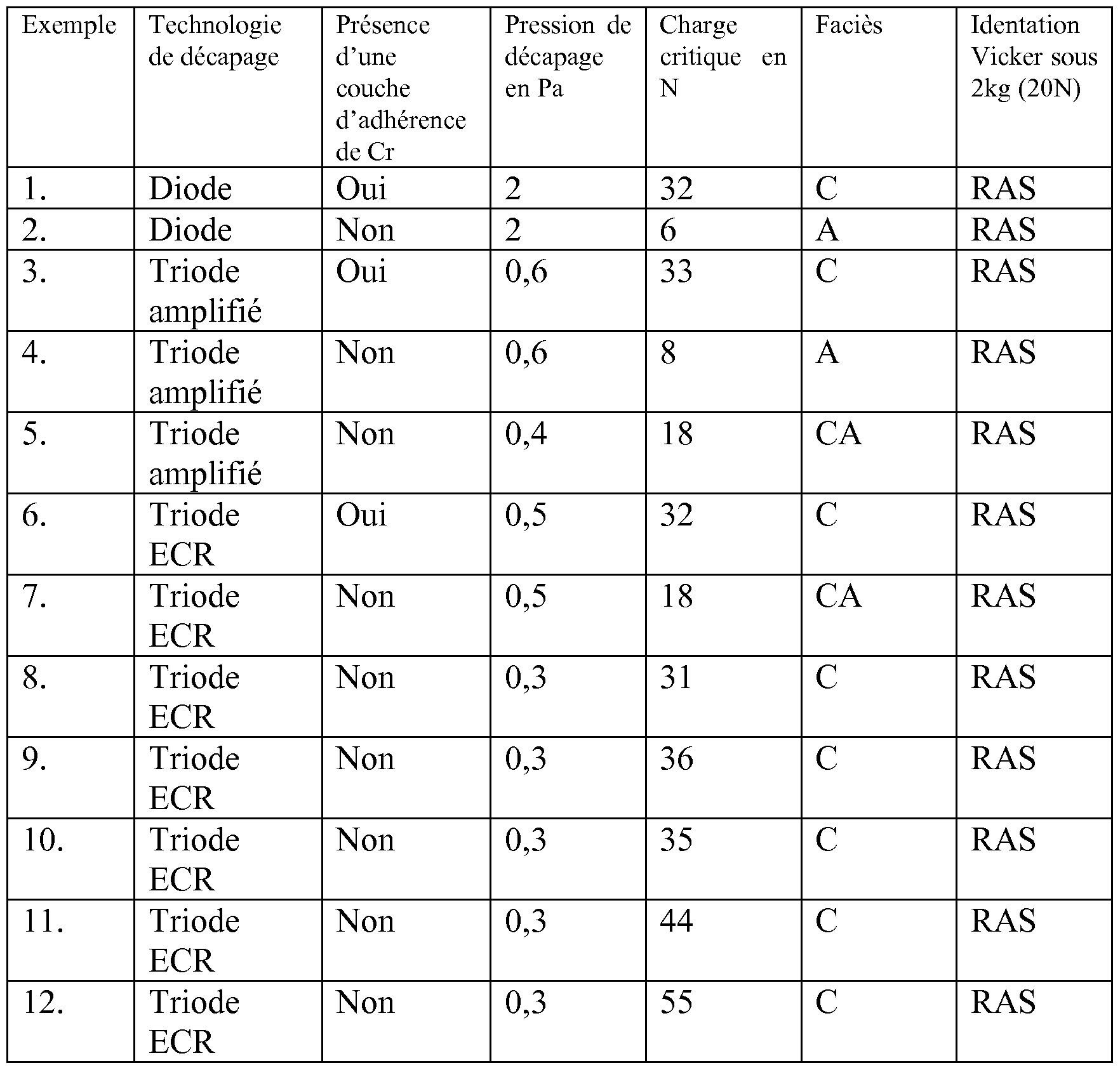
- the experiment matrix was taken up by including the results of the scratch test, obtained on tool steel substrates (hardness 64H C), for total deposit thicknesses of 2.5 ⁇ with no undercoat.
- Examples 1 1 and 12 have stacks of strong thickness, demonstrating the robustness of the invention.
- Example 11 comprises a tungsten-based layer 4 ⁇ thick on which 8 ⁇ of DLC was deposited.
- the thickness of the tungsten layer was increased to 9.7 ⁇ and the surface layer of DLC to 19.2 ⁇ .
- CA cohesive-adhesive
- triode etching technology shows an evolution of the behavior of the scratch deposit in the absence of underlayer of chromium (Examples 4 and 5).
- the critical load increased compared to diode pickling (Example 2) and the scaling mode evolved (Examples 4 and 5)
- the use of the triode microwave technology ECR shows that it is possible to obtain a mechanical behavior quite similar to the state of the art, in the absence of underlayer of chromium (Example 8). It is noted, as in amplified triode technology, that the lowering of pressure results in an improvement of the scratch test behavior (examples 7 and 8).
- Examples 9 and 10 teach that cohesive peel strength is increased through the thickness of the tungsten-containing underlayer, as shown by the critical load values.
- the thickness of the tungsten carbide and the gradient layer is 1.5 ⁇ . More particularly, in Example 9, the thickness of the tungsten carbide has been increased to 1 ⁇ , that corresponding to the carbon content gradient is 0.5 ⁇ . In Example 10, the thickness of the tungsten carbide is 0.2 ⁇ , while the layer with a carbon content gradient is brought to 1.3 ⁇ . Examples 11 and 12 illustrate the robustness of the solution. It is known that the increase of the thickness of the hard thin layers deposited under vacuum results in the increase of the internal compressive stresses. Nevertheless, the scratch test behavior remains cohesive and the increase of the critical load results from the increase in thickness of the tungsten-based layer.
- the results tend to show an improvement in the adhesion of the layers produced without chromium under-layer when the etching pressure decreases.
- the pressure decrease during pickling depends on the technology itself. Typically, diode technology is unable to generate plasma at pressures as low as 0.5 Pa.
- the use of an appropriate pickling technology makes it possible to reduce the argon pressure, and to produce a DLC-type adherent stack without a chromium underlayer, which goes against the general knowledge of those skilled in the art and prior technical solutions.
- the process according to the invention brings many advantages:
- the removal of the adhesion sub-layer results in the disappearance of an interface and therefore an increase in the reliability and robustness of the coating.
Landscapes
- Chemical & Material Sciences (AREA)
- Chemical Kinetics & Catalysis (AREA)
- Engineering & Computer Science (AREA)
- Materials Engineering (AREA)
- Mechanical Engineering (AREA)
- Metallurgy (AREA)
- Organic Chemistry (AREA)
- Inorganic Chemistry (AREA)
- Chemical Vapour Deposition (AREA)
- Physical Vapour Deposition (AREA)
- Forging (AREA)
- Chemically Coating (AREA)
- Mounting, Exchange, And Manufacturing Of Dies (AREA)
- Sampling And Sample Adjustment (AREA)
- Pens And Brushes (AREA)
- Pistons, Piston Rings, And Cylinders (AREA)
- Carbon And Carbon Compounds (AREA)
- Other Surface Treatments For Metallic Materials (AREA)
Abstract
Description

Claims
Priority Applications (19)
| Application Number | Priority Date | Filing Date | Title |
|---|---|---|---|
| MX2013013411A MX361485B (es) | 2011-05-19 | 2012-05-16 | Parte con revestimiento de dlc y metodo para aplicar el revestimiento de dlc. |
| AU2012257680A AU2012257680B2 (en) | 2011-05-19 | 2012-05-16 | Part having a DLC coating and method for applying the DLC coating |
| RS20171348A RS56836B1 (sr) | 2011-05-19 | 2012-05-16 | Deo sa dlc prevlakom i metode za nanošenje dlc prevlake |
| SG2013082300A SG194818A1 (en) | 2011-05-19 | 2012-05-16 | Part having a dlc coating and method for applying the dlc coating |
| ES12728712.6T ES2654290T3 (es) | 2011-05-19 | 2012-05-16 | Pieza con revestimiento DLC y procedimiento de aplicación del revestimiento DLC |
| US14/116,531 US9103016B2 (en) | 2011-05-19 | 2012-05-16 | Part having a DLC coating and method for applying the DLC coating |
| CA2835803A CA2835803C (fr) | 2011-05-19 | 2012-05-16 | Piece avec revetement dlc et procede d'application du revetement dlc |
| EP12728712.6A EP2710168B1 (fr) | 2011-05-19 | 2012-05-16 | Piece avec revetement dlc et procede d'application du revetement dlc |
| SI201231196T SI2710168T1 (en) | 2011-05-19 | 2012-05-16 | DLC SHOULDER AND PROCEDURE FOR DOWNLOADING DLC |
| UAA201313827A UA114790C2 (uk) | 2011-05-19 | 2012-05-16 | Деталь з dlc покриттям і спосіб нанесення dlc покриття |
| KR1020137033475A KR101779844B1 (ko) | 2011-05-19 | 2012-05-16 | Dlc 코팅된 부품 및 dlc 코팅을 도포하는 방법 |
| BR112013029492-2A BR112013029492B1 (pt) | 2011-05-19 | 2012-05-16 | peça metálica, método de aplicação de um revestimento de dlc sobre uma peça metálica e peça metálica revestida de dlc |
| RU2013152884/02A RU2593561C2 (ru) | 2011-05-19 | 2012-05-16 | Деталь с dlc покрытием и способ нанесения dlc покрытия |
| JP2014510866A JP5989766B2 (ja) | 2011-05-19 | 2012-05-16 | Dlcコーティングを有する部品およびdlcコーティングを付着するための方法 |
| CN201280024158.1A CN103547707B (zh) | 2011-05-19 | 2012-05-16 | 具有dlc涂层的零件和应用dlc涂层的方法 |
| PL12728712T PL2710168T3 (pl) | 2011-05-19 | 2012-05-16 | Element z powłoką dlc i sposób nakładania powłoki dlc |
| ZA2013/08376A ZA201308376B (en) | 2011-05-19 | 2013-11-07 | Part having a dlc coating and method for applying the dlc coating |
| TNP2013000475A TN2013000475A1 (fr) | 2011-05-19 | 2013-11-15 | Piece avec revetement dlc et procede d'application du revetement dlc |
| MA36444A MA35157B1 (fr) | 2011-05-19 | 2013-11-15 | Piece avec revetement dlc et procede d'application du revetement dlc |
Applications Claiming Priority (2)
| Application Number | Priority Date | Filing Date | Title |
|---|---|---|---|
| FR1154388 | 2011-05-19 | ||
| FR1154388A FR2975404B1 (fr) | 2011-05-19 | 2011-05-19 | Piece avec revetement dlc et procede d'application du revetement dlc |
Publications (1)
| Publication Number | Publication Date |
|---|---|
| WO2012156647A1 true WO2012156647A1 (fr) | 2012-11-22 |
Family
ID=44512238
Family Applications (1)
| Application Number | Title | Priority Date | Filing Date |
|---|---|---|---|
| PCT/FR2012/051109 WO2012156647A1 (fr) | 2011-05-19 | 2012-05-16 | Piece avec revetement dlc et procede d'application du revetement dlc |
Country Status (24)
| Country | Link |
|---|---|
| US (1) | US9103016B2 (fr) |
| EP (1) | EP2710168B1 (fr) |
| JP (1) | JP5989766B2 (fr) |
| KR (1) | KR101779844B1 (fr) |
| CN (1) | CN103547707B (fr) |
| AU (1) | AU2012257680B2 (fr) |
| BR (1) | BR112013029492B1 (fr) |
| CA (1) | CA2835803C (fr) |
| ES (1) | ES2654290T3 (fr) |
| FR (1) | FR2975404B1 (fr) |
| HU (1) | HUE035981T2 (fr) |
| MA (1) | MA35157B1 (fr) |
| MX (1) | MX361485B (fr) |
| MY (1) | MY166740A (fr) |
| PL (1) | PL2710168T3 (fr) |
| RS (1) | RS56836B1 (fr) |
| RU (1) | RU2593561C2 (fr) |
| SG (1) | SG194818A1 (fr) |
| SI (1) | SI2710168T1 (fr) |
| TN (1) | TN2013000475A1 (fr) |
| TW (1) | TWI537402B (fr) |
| UA (1) | UA114790C2 (fr) |
| WO (1) | WO2012156647A1 (fr) |
| ZA (1) | ZA201308376B (fr) |
Cited By (3)
| Publication number | Priority date | Publication date | Assignee | Title |
|---|---|---|---|---|
| US20160017477A1 (en) * | 2013-03-22 | 2016-01-21 | Nittan Valve Co., Ltd. | Dlc film coating and coated valve lifter |
| WO2018104641A1 (fr) | 2016-12-07 | 2018-06-14 | H.E.F. | Piece de frottement, systeme mecanique comprenant une telle piece de frottement, et procede de mise en oeuvre |
| WO2018130779A1 (fr) | 2017-01-11 | 2018-07-19 | H.E.F. | Piston pour machine thermique, machine thermique comprenant un tel piston, et procedes |
Families Citing this family (4)
| Publication number | Priority date | Publication date | Assignee | Title |
|---|---|---|---|---|
| FR3011305B1 (fr) * | 2013-09-27 | 2016-02-05 | Hydromecanique & Frottement | Axe de piston |
| EP3039315B8 (fr) | 2013-08-30 | 2018-02-14 | H.E.F. | Axe de piston et procédé d'application d'un revêtement antigrippant sur l'axe |
| US11499643B2 (en) * | 2017-08-04 | 2022-11-15 | Oerlikon Surface Solutions Ag, Pfäffikon | Coated valve components with corrosion resistant sliding surfaces |
| FR3082526B1 (fr) | 2018-06-18 | 2020-09-18 | Hydromecanique & Frottement | Piece revetue par un revetement de carbone amorphe hydrogene sur une sous-couche comportant du chrome, du carbone et du silicium |
Citations (4)
| Publication number | Priority date | Publication date | Assignee | Title |
|---|---|---|---|---|
| WO2001079585A1 (fr) | 2000-04-12 | 2001-10-25 | Unaxis Balzers Aktiengesellschaft | Systeme de couches dlc et procede pour produire un tel systeme |
| DE102007058356A1 (de) * | 2007-06-20 | 2008-12-24 | Systec System- Und Anlagentechnik Gmbh & Co.Kg | PVD-Verfahren und PVD-Vorrichtung zur Erzeugung von reibungsarmen, verschleißbeständigen Funktionsschichten und damit hergestellte Beschichtungen |
| WO2011018252A1 (fr) | 2009-08-13 | 2011-02-17 | Federal-Mogul Burscheid Gmbh | Élément de coulissement, en particulier segment de piston, doté d'un revêtement |
| EP2362000A1 (fr) * | 2008-10-29 | 2011-08-31 | NTN Corporation | Corps formant un film multicouche dur et son procédé de fabrication |
Family Cites Families (15)
| Publication number | Priority date | Publication date | Assignee | Title |
|---|---|---|---|---|
| JPH0676666B2 (ja) * | 1987-02-10 | 1994-09-28 | 株式会社半導体エネルギ−研究所 | 炭素膜作製方法 |
| JPH0762541A (ja) * | 1993-08-26 | 1995-03-07 | Kyocera Corp | 耐摩耗性部材 |
| RU2184644C2 (ru) * | 1997-07-16 | 2002-07-10 | Дзе Исизука Рисерч Инститьют, Лтд. | Алмазосодержащий слоистый композит и способ его получения |
| JP2000256850A (ja) * | 1999-03-04 | 2000-09-19 | Riken Corp | ダイヤモンドライクカーボン薄膜及びその製造方法 |
| RU2238922C2 (ru) * | 2000-03-15 | 2004-10-27 | Хардид Лимитед | Адгезионное композиционное покрытие на алмазах, алмазосодержащих материалах и способ его нанесения |
| JP4022048B2 (ja) * | 2001-03-06 | 2007-12-12 | 株式会社神戸製鋼所 | ダイヤモンドライクカーボン硬質多層膜成形体およびその製造方法 |
| JP4139102B2 (ja) * | 2001-12-06 | 2008-08-27 | 株式会社デンソー | ダイヤモンドライクカーボン硬質多層膜成形体およびその製造方法 |
| JP4473592B2 (ja) * | 2003-02-07 | 2010-06-02 | カヤバ工業株式会社 | Dlcコーティング膜 |
| JP2005243093A (ja) * | 2004-02-24 | 2005-09-08 | Fuji Electric Device Technology Co Ltd | 垂直磁気記録媒体およびその製造方法 |
| JP2007070667A (ja) * | 2005-09-05 | 2007-03-22 | Kobe Steel Ltd | ダイヤモンドライクカーボン硬質多層膜成形体およびその製造方法 |
| US7963852B2 (en) * | 2005-10-07 | 2011-06-21 | Jtekt Corporation | Spline shaft |
| JP4704950B2 (ja) * | 2006-04-27 | 2011-06-22 | 株式会社神戸製鋼所 | 非晶質炭素系硬質多層膜及びこの膜を表面に備えた硬質表面部材 |
| DE102008042747A1 (de) * | 2008-10-10 | 2010-04-15 | Federal-Mogul Burscheid Gmbh | Gleitelement in einem Verbrennungsmotor, insbesondere Kolbenring |
| JP5393108B2 (ja) * | 2008-10-29 | 2014-01-22 | Ntn株式会社 | 硬質多層膜成形体の製造方法 |
| JP5222764B2 (ja) * | 2009-03-24 | 2013-06-26 | 株式会社神戸製鋼所 | 積層皮膜および積層皮膜被覆部材 |
-
2011
- 2011-05-19 FR FR1154388A patent/FR2975404B1/fr not_active Expired - Fee Related
-
2012
- 2012-05-16 UA UAA201313827A patent/UA114790C2/uk unknown
- 2012-05-16 CA CA2835803A patent/CA2835803C/fr active Active
- 2012-05-16 BR BR112013029492-2A patent/BR112013029492B1/pt active IP Right Grant
- 2012-05-16 MY MYPI2013004183A patent/MY166740A/en unknown
- 2012-05-16 US US14/116,531 patent/US9103016B2/en active Active
- 2012-05-16 KR KR1020137033475A patent/KR101779844B1/ko active IP Right Grant
- 2012-05-16 ES ES12728712.6T patent/ES2654290T3/es active Active
- 2012-05-16 AU AU2012257680A patent/AU2012257680B2/en active Active
- 2012-05-16 RS RS20171348A patent/RS56836B1/sr unknown
- 2012-05-16 SI SI201231196T patent/SI2710168T1/en unknown
- 2012-05-16 WO PCT/FR2012/051109 patent/WO2012156647A1/fr active Application Filing
- 2012-05-16 CN CN201280024158.1A patent/CN103547707B/zh active Active
- 2012-05-16 EP EP12728712.6A patent/EP2710168B1/fr active Active
- 2012-05-16 MX MX2013013411A patent/MX361485B/es active IP Right Grant
- 2012-05-16 SG SG2013082300A patent/SG194818A1/en unknown
- 2012-05-16 RU RU2013152884/02A patent/RU2593561C2/ru active
- 2012-05-16 PL PL12728712T patent/PL2710168T3/pl unknown
- 2012-05-16 HU HUE12728712A patent/HUE035981T2/hu unknown
- 2012-05-16 JP JP2014510866A patent/JP5989766B2/ja active Active
- 2012-05-17 TW TW101117560A patent/TWI537402B/zh active
-
2013
- 2013-11-07 ZA ZA2013/08376A patent/ZA201308376B/en unknown
- 2013-11-15 TN TNP2013000475A patent/TN2013000475A1/fr unknown
- 2013-11-15 MA MA36444A patent/MA35157B1/fr unknown
Patent Citations (4)
| Publication number | Priority date | Publication date | Assignee | Title |
|---|---|---|---|---|
| WO2001079585A1 (fr) | 2000-04-12 | 2001-10-25 | Unaxis Balzers Aktiengesellschaft | Systeme de couches dlc et procede pour produire un tel systeme |
| DE102007058356A1 (de) * | 2007-06-20 | 2008-12-24 | Systec System- Und Anlagentechnik Gmbh & Co.Kg | PVD-Verfahren und PVD-Vorrichtung zur Erzeugung von reibungsarmen, verschleißbeständigen Funktionsschichten und damit hergestellte Beschichtungen |
| EP2362000A1 (fr) * | 2008-10-29 | 2011-08-31 | NTN Corporation | Corps formant un film multicouche dur et son procédé de fabrication |
| WO2011018252A1 (fr) | 2009-08-13 | 2011-02-17 | Federal-Mogul Burscheid Gmbh | Élément de coulissement, en particulier segment de piston, doté d'un revêtement |
Non-Patent Citations (1)
| Title |
|---|
| REBHOLZ: "Deposition and characterisation of carbon-containing tungsten coatings prepared by reactive magnetron sputtering", VACUUM, vol. 49, no. 4, 1 January 1998 (1998-01-01), pages 265, XP055014773, ISSN: 0042-207X * |
Cited By (6)
| Publication number | Priority date | Publication date | Assignee | Title |
|---|---|---|---|---|
| US20160017477A1 (en) * | 2013-03-22 | 2016-01-21 | Nittan Valve Co., Ltd. | Dlc film coating and coated valve lifter |
| EP2957655A4 (fr) * | 2013-03-22 | 2017-01-25 | Nittan Valve Co., Ltd. | Film de revêtement à base de carbone sous forme de diamant amorphe (cda) et poussoir de soupape revêtu |
| US9657384B2 (en) * | 2013-03-22 | 2017-05-23 | Nittan Valve Co., Ltd. | DLC film coating and coated valve lifter |
| WO2018104641A1 (fr) | 2016-12-07 | 2018-06-14 | H.E.F. | Piece de frottement, systeme mecanique comprenant une telle piece de frottement, et procede de mise en oeuvre |
| WO2018130779A1 (fr) | 2017-01-11 | 2018-07-19 | H.E.F. | Piston pour machine thermique, machine thermique comprenant un tel piston, et procedes |
| US11098674B2 (en) | 2017-01-11 | 2021-08-24 | H.E.F. | Piston for a heat engine, heat engine comprising such a piston, and methods |
Also Published As
Similar Documents
| Publication | Publication Date | Title |
|---|---|---|
| CA2835803C (fr) | Piece avec revetement dlc et procede d'application du revetement dlc | |
| JP6654797B2 (ja) | 内燃エンジン用スチールピストン及びその製造方法 | |
| FR2926672A1 (fr) | Procede de fabrication de couches de materiau epitaxie | |
| WO2008059791A1 (fr) | Film de revêtement en nitrure de chrome par dépôt ionique, son procédé de fabrication et segment de piston pour moteur à combustion interne | |
| JP6890703B2 (ja) | 内燃機関用のライナー | |
| JP4117388B2 (ja) | 保護膜 | |
| Moghal et al. | Investigation of the mechanical properties of aluminium oxide thin films on polymer substrates by a combination of fragmentation and scratch testing | |
| JP4356078B2 (ja) | 保護膜 | |
| EP2209928A1 (fr) | Procede de realisation de revetement en carbone amorphe hydrogene | |
| FR3073082A1 (fr) | Procede de fabrication d'un film sur un support presentant une surface non plane | |
| EP2976443B1 (fr) | Structure anti-érosion pour aéronefs | |
| JP2009211791A (ja) | 磁気記録媒体の製造方法及び製造装置 | |
| EP3976847A1 (fr) | Procédé de protection contre la corrosion | |
| CN116356254A (zh) | 提高硬质涂层疲劳寿命的多层硬质涂层结构及其制备方法 | |
| FR2966533A1 (fr) | Organe de frottement pour l'assemblage de deux pieces. | |
| EP3390685A1 (fr) | Procédé de protection d'une surface métallique d'une pièce par un revêtement en diamant et pièce ainsi obtenue |
Legal Events
| Date | Code | Title | Description |
|---|---|---|---|
| 121 | Ep: the epo has been informed by wipo that ep was designated in this application |
Ref document number: 12728712 Country of ref document: EP Kind code of ref document: A1 |
|
| WWE | Wipo information: entry into national phase |
Ref document number: 2012728712 Country of ref document: EP |
|
| WWE | Wipo information: entry into national phase |
Ref document number: 14116531 Country of ref document: US |
|
| ENP | Entry into the national phase |
Ref document number: 2835803 Country of ref document: CA |
|
| WWE | Wipo information: entry into national phase |
Ref document number: MX/A/2013/013411 Country of ref document: MX |
|
| ENP | Entry into the national phase |
Ref document number: 2014510866 Country of ref document: JP Kind code of ref document: A |
|
| NENP | Non-entry into the national phase |
Ref country code: DE |
|
| ENP | Entry into the national phase |
Ref document number: 2013152884 Country of ref document: RU Kind code of ref document: A |
|
| WWE | Wipo information: entry into national phase |
Ref document number: A201313827 Country of ref document: UA |
|
| ENP | Entry into the national phase |
Ref document number: 2012257680 Country of ref document: AU Date of ref document: 20120516 Kind code of ref document: A |
|
| ENP | Entry into the national phase |
Ref document number: 20137033475 Country of ref document: KR Kind code of ref document: A |
|
| REG | Reference to national code |
Ref country code: BR Ref legal event code: B01A Ref document number: 112013029492 Country of ref document: BR |
|
| ENP | Entry into the national phase |
Ref document number: 112013029492 Country of ref document: BR Kind code of ref document: A2 Effective date: 20131114 |